Article

Possibilities of Ammonia as Both Fuel and NOx Reductant in Marine Engines: A Numerical Study

1
Nautical Sciences and Marine Engineering Department, University of A Coruña, Mendizabal s/n, 15403 Ferrol, A Coruña, Spain
2
Industrial Engineering Department, University of A Coruña, Mendizabal s/n, 15403 Ferrol, A Coruña, Spain
3
Department of Mechanical Engineering, Mississippi State University, Starkville, MS 39762, USA
*
Author to whom correspondence should be addressed.
J. Mar. Sci. Eng. 2022, 10(1), 43; https://doi.org/10.3390/jmse10010043
Submission received: 27 November 2021 / Revised: 20 December 2021 / Accepted: 24 December 2021 / Published: 1 January 2022
(This article belongs to the Special Issue Marine Engines Performance and Emissions II)

Abstract

:
Nowadays, the environmental impact of shipping constitutes an important challenge. In order to achieve climate neutrality as soon as possible, an important priority consists of progressing on the decarbonization of marine fuels. Free-carbon fuels, used as single fuel or in a dual-fuel mode, are gaining special interest for marine engines. A dual fuel ammonia-diesel operation is proposed in which ammonia is introduced with the intake air. According to this, the present work analyzes the possibilities of ammonia in marine diesel engines. Several ammonia-diesel proportions were analyzed, and it was found that when the proportion of ammonia is increased, important reductions of carbon dioxide, carbon monoxide, and unburnt hydrocarbons are obtained, but at the expense of increments of oxides of nitrogen (NOx), which are only low when too small or too large proportions of ammonia are employed. In order to reduce NOx too, a second ammonia injection along the expansion stroke is proposed. This measure leads to important NOx reductions.

1. Introduction

Marine transport, mainly powered by diesel engines, accounts for more than 90% of the transport of international trade goods [1]. The climate impact of shipping is one of the most important areas of ecology since ships are responsible for 2.2% of carbon dioxide (CO2), 20.8% of nitrogen oxides (NOx), 11.8% of sulfur oxides (SOx), 8.57% of particulate matter 2.5 (PM2.5), and 4.63% of particulate matter 10 (PM10) emissions worldwide in 2019 [2,3]. Several restrictions have been imposed to reduce emissions from ships. The most crucial ones are included in the 73/78 MARPOL convention, (International Convention for the Prevention of Pollution from Ships), by the International Maritime Organization (IMO). This convention, which came into force in 2005 and is revised periodically, regulates several aspects of marine environmental pollution and has recently proposed a decarbonization strategy. One of the objectives of the IMO is the decarbonization of marine diesel engines as soon as possible along this century. Although renewable natural fuels such as biodiesel are gaining importance [4], carbon-free fuels are crucial to achieving the decarbonization of diesel engines. Two promising fuels which fulfill this requirement are hydrogen (H2) and ammonia (NH3). These fuels do not contain carbon nor sulfur and thus their combustion does not generate carbon emissions (CO2, CO, HC, soot), or SOx. Despite the good performance and low emissions of hydrogen, its storage is too complicated to be employed in marine engines [5]. Nevertheless, storage and distribution of ammonia are much easier. Besides, there is available infrastructure for the storage and transport of ammonia which can be used. Ammonia can be easily liquefied and stored at moderate pressures and temperatures, which makes ammonia easy to store on a ship. On the other hand, hydrogen needs pressures that are too high at ambient temperature or too low, around 20 K [6]. According to this, ammonia storage is considerably cheaper than hydrogen storage. Another advantage of ammonia is that its manipulation under safe conditions is well documented. On the other hand, the main disadvantages are NH3 slip and emissions of NOx and N2O. Ammonia is toxic, and its high slip concentration leads to risks and eutrophication.
Ammonia was first used as fuel in 1822. Sir Goldsworghy Gurney was the first person who used ammonia as fuel and applied it to a locomotive. The application of ammonia as fuel presents two main periods in history: developing an alternative fuel to face any oil crisis and, in the recent period, protecting the environment. The 1940s was an important decade for ammonia as a fuel due to the shortage of conventional fossil fuels during World War II. After World War II, the goal of engineers was to focus on alternative fuels to face any other possible future oil crisis. After this research, no significant research about ammonia as fuel was developed for a long time. However, ammonia has regained interest in recent years due to environmental reasons. It is worth mentioning that, despite it being applied as a fuel many years ago, the research of ammonia as a fuel for internal combustion engines is still in its infancy.
The literature shows that ammonia can be used in both spark ignition (SI) and compression ignition (CI) engines [7,8,9,10,11]. In SI engines, an important advantage is the high-octane number of ammonia, which improves the combustion properties and knock (when the fuel is abnormally auto ignited in local hot spots). On the other hand, the combustion of ammonia in CI engines is much more difficult due to the high autoignition temperature, narrow flammability limits, low flame speed, and high heat of vaporization. An appropriate performance in CI operation was only achieved with high compression ratios required for the autoignition of the fuel [7]. However, the option of partially replacing diesel fuel with ammonia in a dual fuel operation is a realistic option since diesel can be used to start the combustion of the mixture. Several authors obtained satisfactory combustion when ammonia gas is mixed into the intake air [8,9,10,11,12,13,14]. Regarding the marine field, currently, there are no commercial solutions but the main marine engines manufacturers such as MAN B&W, Wärtsilä, Caterpillar, etc., are developing encouraging studies to employ ammonia as fuel [15].
In the present work, ammonia is proposed to be used as a fuel for marine diesel engines. A dual fuel mode was analyzed using CFD (computational fluid dynamics), in which ammonia gas is introduced into the air-intake manifold, while diesel fuel was injected directly into the cylinder to trigger the mixture. Since one of the main drawbacks of ammonia is NOx production, a second ammonia injection along the expansion stroke is proposed. This second injection leads to important NOx reductions.

2. Materials and Methods

The engine analyzed in the present work, the MAN D2840LE V10, is a four-stroke diesel engine with 10 V-form cylinders and 18270 cm3 cylinder displacement volume. Each cylinder has one inlet and one exhaust valve, and the fuel injector is placed at the center of the cylinder head. The main characteristics at 100% load are summarized in Table 1.
Regarding the CFD model, Figure 1 shows the computational mesh at the bottom dead center position. A deforming mesh was employed in order to implement the movement of the valves and pistons.
The CFD simulations were carried out through the open software OpenFOAM. As diesel combustion, ammonia combustion, and NOx reduction schemes, the models of Ra and Reitz [16], Mathieu and Peterson [17], and Miller and Glarborg [18] were employed, respectively. The fuel heat-up and evaporation were treated through the Dukowicz [19] model and the fuel droplet breakup through the Kelvin-Helmoltz and Rayleigh-Taylor [20] model. The CFD model is based on the equations of conservation of mass, momentum, and energy, Equations (1)–(3), respectively.
ρ t + x i ( ρ u i ) = 0
t ( ρ u i ) + x j ( ρ u i u j ) = p x i + τ i j x j + x j ( ρ u i u j ¯ )
t ( ρ H ) + x i ( ρ u i H ) = x i ( μ t σ h H x i ) + S r a d
where ρ represents the density, τij the viscous stress tensor, σh the turbulent Prandtl number, μt the turbulent viscosity, and H the total enthalpy. The chemical reactions were treated through additional equations. Given a set of N species and m reactions, Equation (4), the local mass fraction of each species, fk, can be expressed by Equation (5).
k = 1 N v k j M k k j k = 1 N v k j M k    j = 1 , 2 ,   ,   m
t ( ρ f k ) + x i ( ρ u i f k ) = x i ( μ t S c t f k x i ) + S k
where v k j are the stoichiometric coefficients of the reactant species Mk in the reaction j, v k j the stoichiometric coefficients of the product species Mk in the reaction j, Sct the turbulent Smidth number and Sk the net rate of production of the species Mk by chemical reaction, given by the molecular weight multiplied by the production rate of the species, Equation (6).
S k = M W k d [ M k ] d t
where MWk is the molecular weight of the species Mk and [Mk] its concentration. The net progress rate is given by the production of the species Mk minus the destruction of the species Mk along the m reactions:
d [ M k ] d t = j = 1 m { ( v k j v k j ) [ k f j k = 1 N [ M k ] v k j k b j k = 1 N [ M k ] v k j ] }
where kfj and kfb are the forward and backward reaction rate constants for each reaction j.
Operating under diesel, the validation with experimental results was developed in previous works [21,22,23] and thus is not shown here in detail. Figure 2 illustrates the experimentally and numerically obtained in-cylinder pressure against the crank angle at 100% load and Figure 3 the experimentally and numerically obtained SFC (specific fuel consumption) and emissions at several loads. In the experimental tests, the gas analyzers Gasboard-3000 and Gasboard-3030 were employed. Operating under the dual fuel mode ammonia-diesel, the validation using experimental results was not realized due to safety reasons. Ammonia is highly toxic and any accident during the experimental sets could have dramatic consequences for the staff. Nevertheless, the ammonia combustion mechanism was validated for several equivalence ratios, temperatures, and pressures elsewhere [17], in which satisfactory results have been obtained for the species concentrations. NOx is mainly produced by thermal, fuel and prompt mechanisms, and Mathieu and Peterson found that their model is able to accurately predict NOx.
Regarding Figure 2, the relation between the crank angle and volume is given by Equation (8) [24].
V = V c + π B 2 4 ( L + A A cos θ L 2 A 2 sin 2 θ )
where V is the cylinder volume, Vc is the clearance volume, B the bore, L the connecting rod length, A the crank radius and θ the crank angle.

3. Results and Discussion

Once validated, this CFD model was employed to analyze the dual-mode ammonia-diesel operation. Different proportions of diesel and ammonia were employed under the same power, 320 kW, corresponding to the nominal power using diesel fuel alone. The intake energy rate from diesel or ammonia fuel was computed by the fuel flow rate multiplied by the lower heating value. According to this, the energy contribution from diesel fuel can be obtained by the following expression:
E ˙ d i e s e l = m ˙ d i e s e l L H V d i e s e l m ˙ d i e s e l L H V d i e s e l + m ˙ N H 3 L H V N H 3
where m ˙ d i e s e l and m ˙ N H 3 are the fuel flow rate of diesel and ammonia, respectively, while LHVdiesel and LHVNH3 are the lower heating value of diesel and ammonia, respectively.
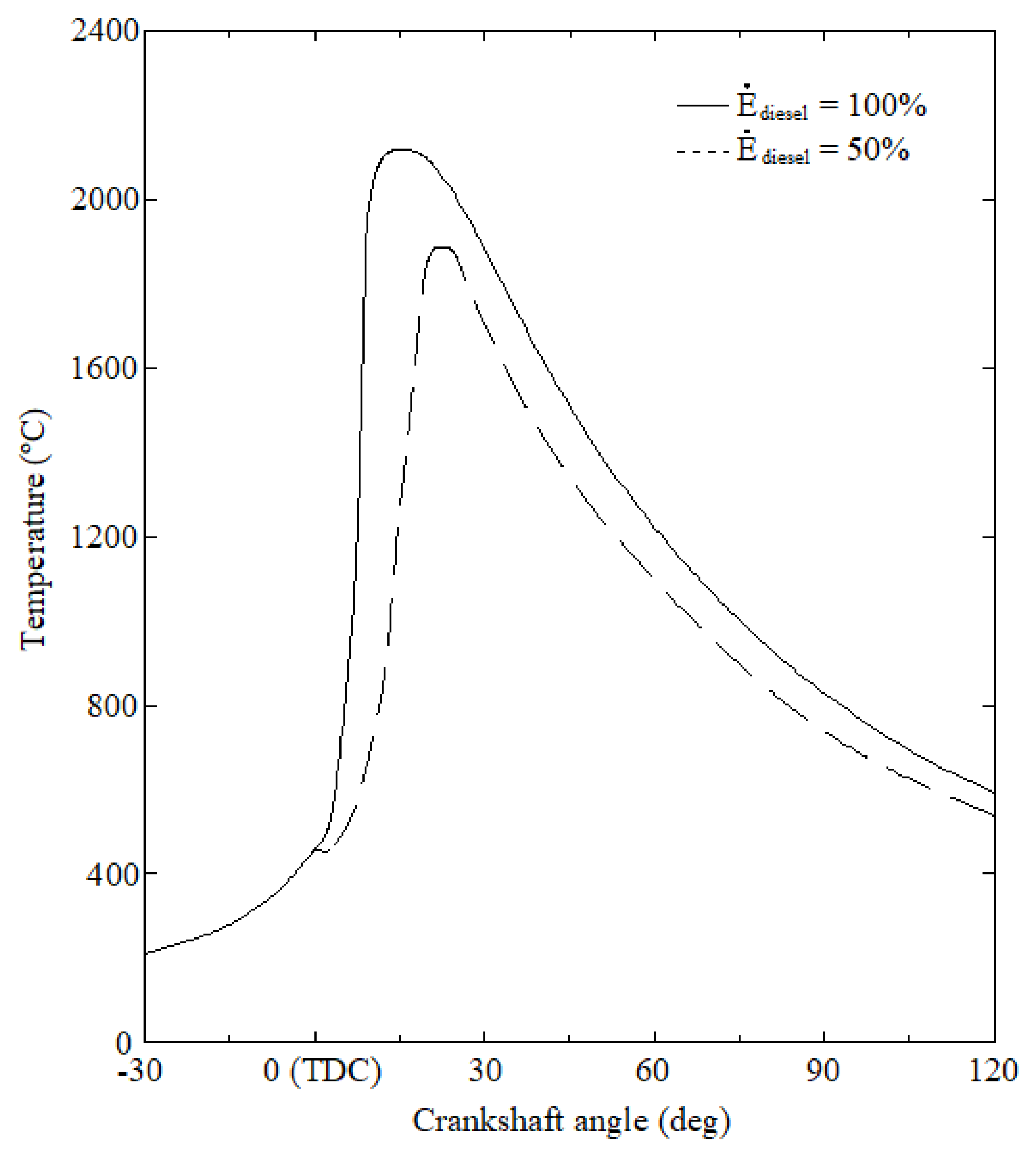
Several experimental results available in the literature concluded that a 100% ammonia fuel mode (i.e., E ˙ d i e s e l = 0 ) leads to performance problems in compression ignition engines because ammonia has a high resistance to autoignition [25,26]. According to this, the power contribution from diesel fuel analyzed in the present work encompasses the range from 10 to 100%. It is worth mentioning that it is possible to reach 320 kW using only 10% diesel power contribution but at expenses of an excessive ammonia fuel contribution and thus considerable emissions of non-reacted ammonia to the exhaust gas. Nevertheless, these low proportions of power contribution from diesel fuel were also analyzed for illustrative purposes. Regarding NOx, it is well-known that almost all NOx produced by compression ignition engines is NO [22,27]. The NO emissions obtained in the present work against the power contribution from diesel fuel are shown in Figure 4. On the one hand, ammonia promotes NO emissions due to its nitrogen content. On the other hand, ammonia leads to lower combustion temperatures (Figure 5 illustrates the in-cylinder average temperature under 50% and 100% power contribution from diesel fuel). Since the main source of NO in internal combustion engines are the high temperatures that are reached in the cylinder [28,29,30,31], a reduction of these temperatures leads to a NO emission reduction too. These opposed effects between promoting/mitigating NO formation by ammonia fuel make the net result unpredictable and are responsible for the pattern shown in Figure 4. Under low power contributions from diesel fuel, the quantity of ammonia introduced into the cylinder is so excessive that the NO emissions are high. As the power contribution from diesel fuel is increased, the quantity of ammonia is reduced, and thus NO emissions. At around 70% power contribution from diesel fuel, the NO emissions are minimal and these slightly increase again when the power contribution from diesel fuel is increased due to the increment of the combustion temperature.
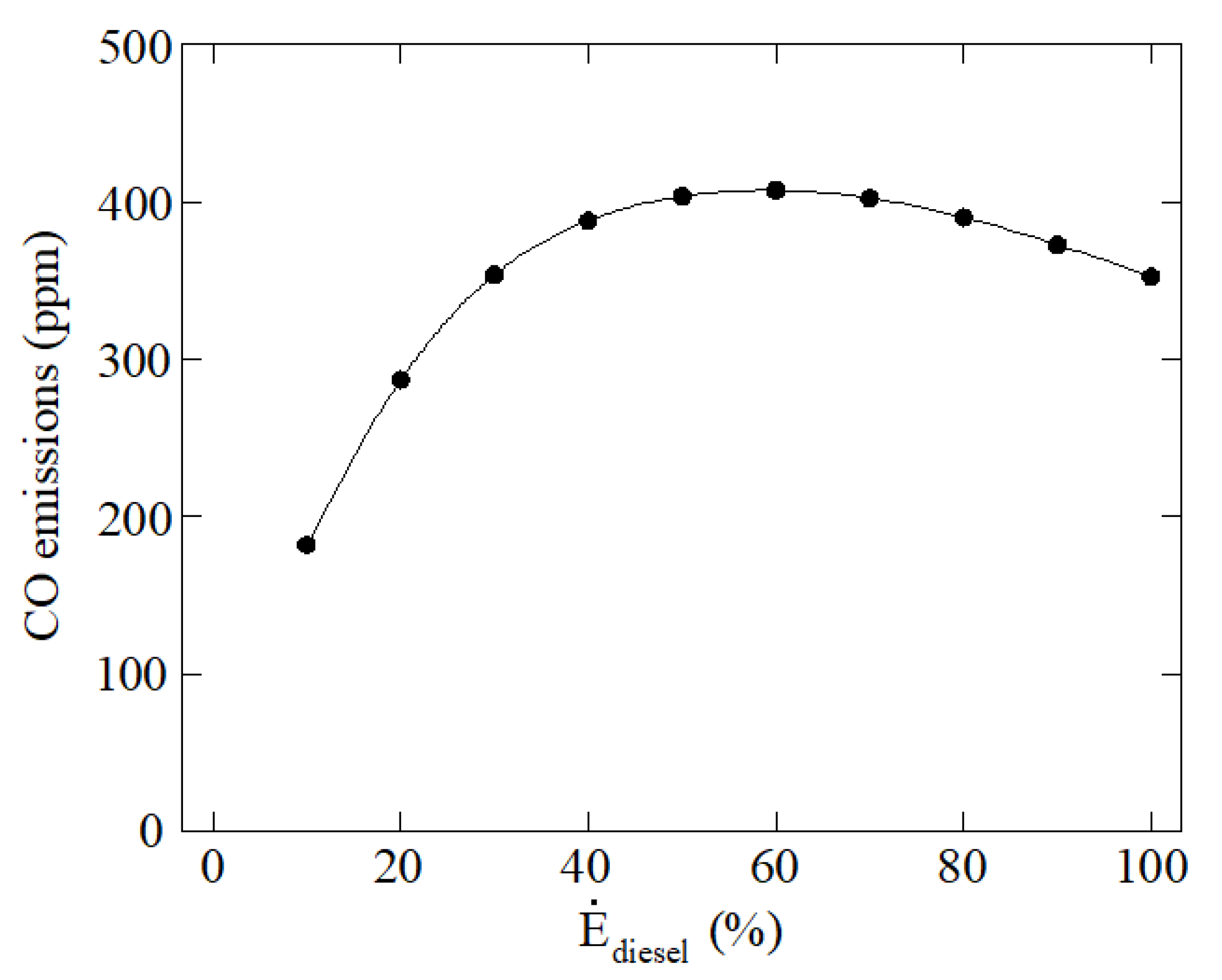
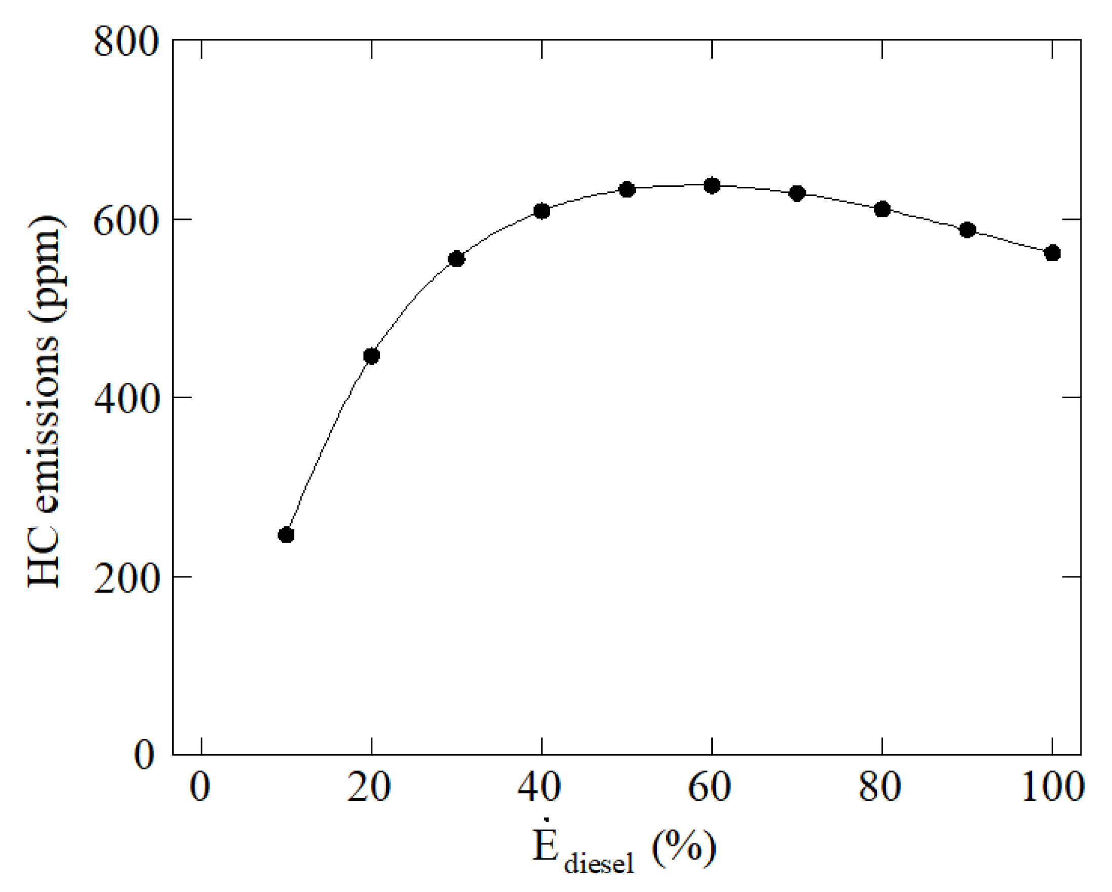
Regarding CO and HC emissions, these are shown in Figure 6 and Figure 7, respectively. As in the case of NO, two opposed effects can also be found. On the one hand, high quantities of ammonia promote less CO and HC emissions due to the lower carbon content of the whole fuel, since ammonia has no carbon. On the other hand, the lower combustion temperatures obtained when using ammonia promote incomplete combustion and thus lead to CO and HC formation. HC and CO are produced mainly by the slow combustion and partial burning caused by lower combustion temperatures. These opposing effects can be shown in Figure 6 and Figure 7. As can be seen, when the power contribution from diesel fuel is low the CO and HC emissions are low too, these increment to a maximum value corresponding to around 50% power contribution from diesel fuel. From this power contribution, the CO and HC emissions decrease again.
CO2 emissions are illustrated in Figure 8. These emissions are clearly reduced as diesel fuel contribution is reduced too due to the lower carbon content when more ammonia and less diesel is employed as fuel. The relation between the power contribution from diesel fuel and CO2 emissions is not linear because when the power contribution from diesel fuel is low the proportion of ammonia in the fuel is too high to reach the 320 kW established. The heating value of ammonia, 18.6 MJ/kg, is considerably lower than the heating value of diesel, 42.4 MJ/kg. According to this, CO2 is drastically reduced under low power contributions from diesel fuel since the quantity of diesel fuel is much lower than the quantity of ammonia fuel.
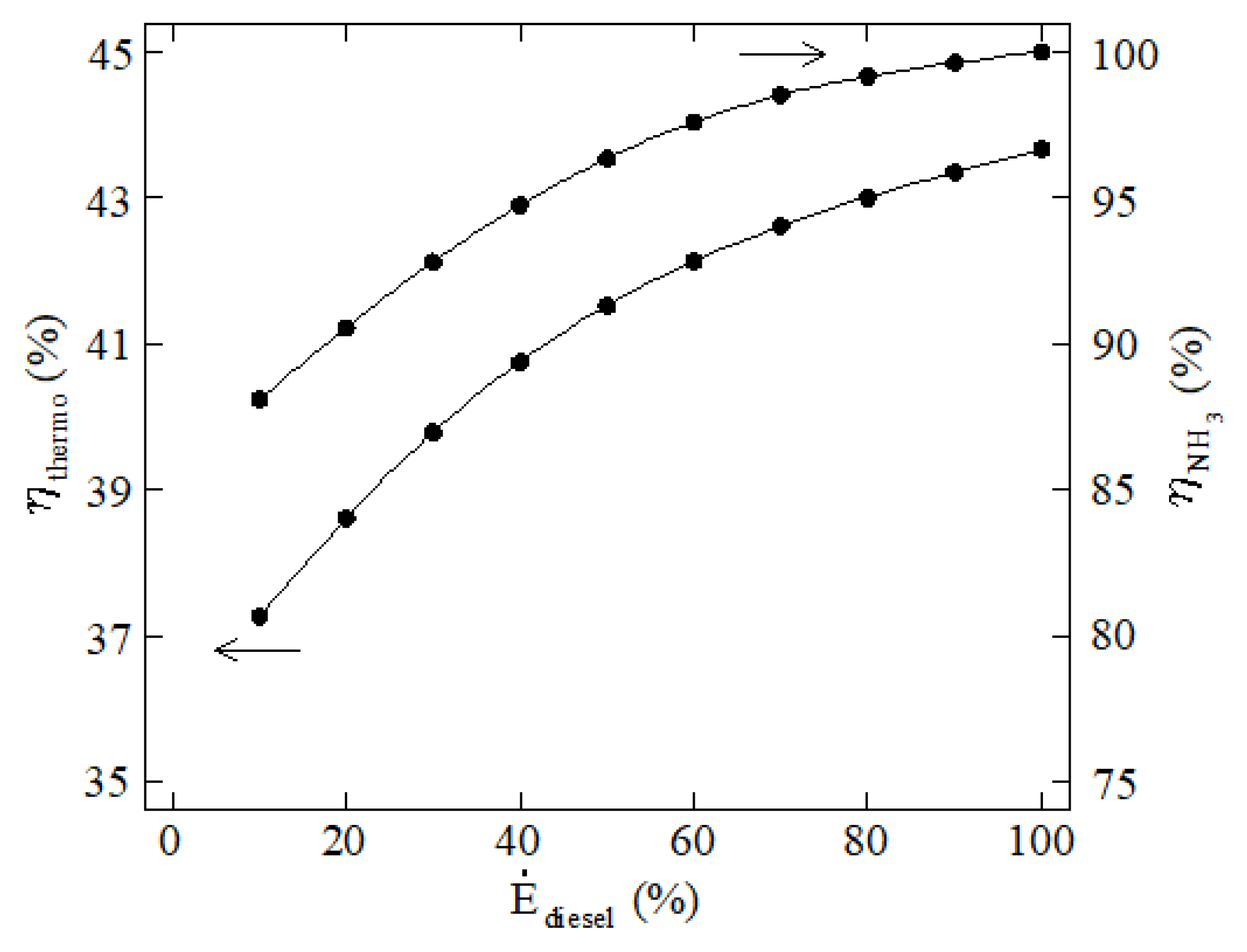
The thermodynamic efficiency is shown in Figure 9. As can be seen, this efficiency decreases as more ammonia is employed. The main reason is that ammonia does not burn completely, and a proportion of the intake ammonia is emitted with the exhaust gases. Another reason is that as more ammonia is employed the compression ratio is reduced. Since the efficiency is related to the compression ratio, this is another reason that explains the reduction of thermodynamic efficiency when using ammonia. The ammonia utilization efficiency is also represented in Figure 9, which was computed through the following expression:
η N H 3 = 1 m ˙ N H 3 o u t p u t m ˙ N H 3 i n p u t
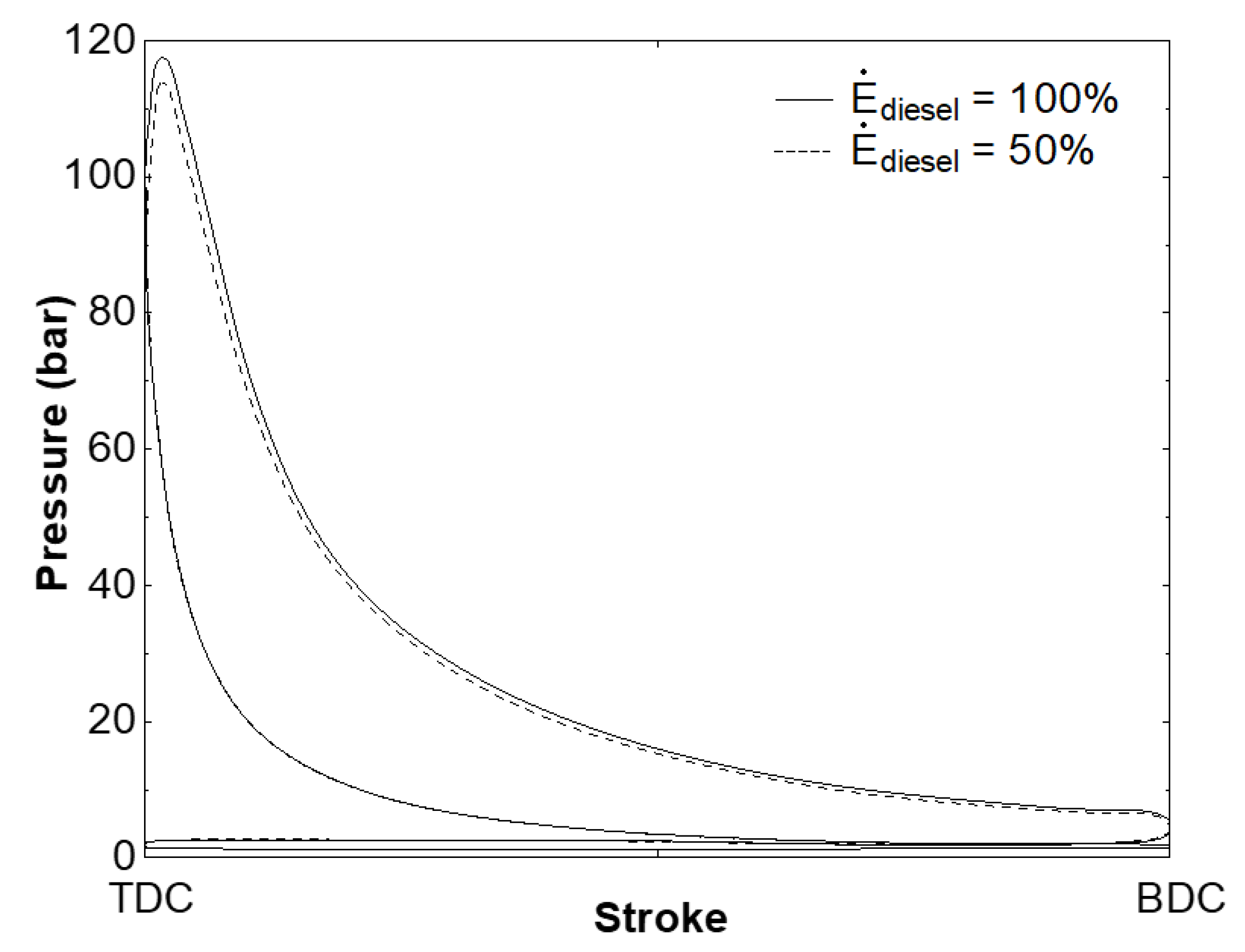
Figure 10 shows the in-cylinder pressure against the whole cycle for 50% and 100% diesel contribution. As can be seen, the pressure is reduced when ammonia is employed.
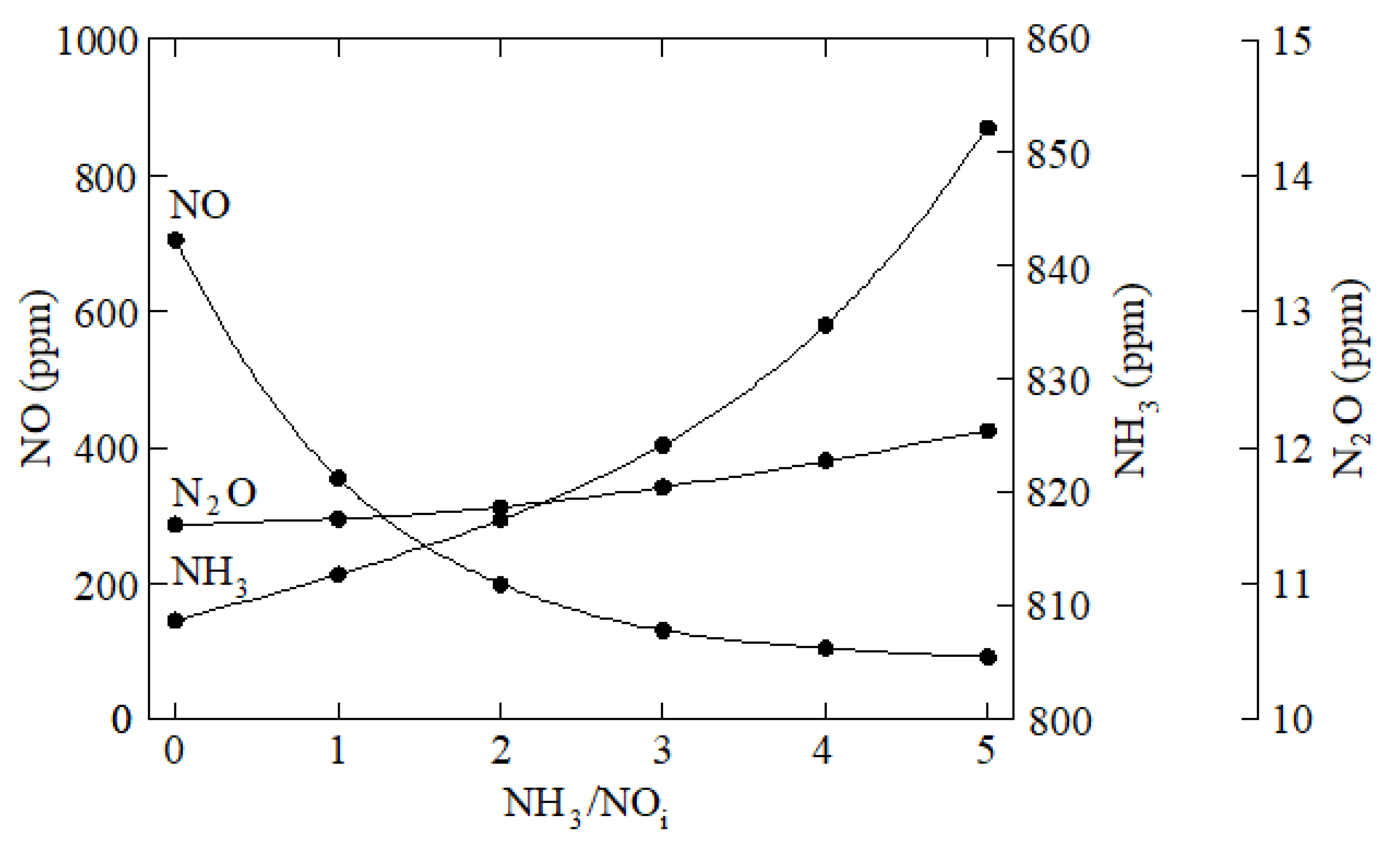
Besides fuel, another application of ammonia consists of NOx reduction agent. Ammonia is highly employed in SCR (Selective Catalytic Reduction) and SNCR (selective non-catalytic reduction) post-treatments. The main disadvantage of SNCR is that this procedure is only efficient in a narrow temperature range, around 1100–1400 K, considerably higher than the usual temperatures of flue gas from diesel engines. In SCR, the NOx reduction can be realized at the common temperatures of flue gas from diesel engines by the use of catalysts. The main disadvantages of SCR are the price and limited durability of catalysts. According to this, the present work proposes to realize an additional ammonia injection along the expansion stroke, when the in-cylinder temperature is optimal for NOx reduction. For instance, the low NO emissions obtained for 70% power contribution from diesel fuel in Figure 4 can be further reduced by injecting ammonia along the expansion stroke. Particularly, in Figure 8 ammonia was injected at 40° crankshaft angle after top dead center, and several ammonia to initial NO (NOi) ratios were analyzed. As can be seen in Figure 9, NO emissions are highly reduced, but it is worth mentioning the increment of non-reacting ammonia into the exhaust gas when too much ammonia is employed. This non-reacting ammonia is called ammonia slip. According to this, this measure requires precise control of the ammonia injection rate to avoid too high ammonia emissions to the atmosphere. This problem is also characteristic of SCR systems, which also require precise control of the ammonia injected. Another handicap of ammonia consists of the formation of N2O, which has a high global warming effect. Figure 11 also includes N2O emissions, which increase as more ammonia is introduced into the engine.

4. Conclusions

The present work focuses on ammonia application as an alternative fuel to be used in compression ignition engines, especially marine engines. The goal is the decarbonization of the marine field. A dual fuel mode based on ammonia injection with the intake air was modeled through CFD. Different proportions of diesel and ammonia were analyzed. It was found that the thermodynamic efficiency was reduced as more ammonia is employed, which leads to a higher engine energy consumption when using ammonia compared to diesel fuel. As expected, a considerable reduction of CO2 was obtained when using ammonia since this fuel does not contain carbon. Regarding CO and HC emissions, too high ammonia proportions led to low CO and HC emissions. On the other hand, too low ammonia proportions also reduce CO and HC emissions due to the higher combustion temperatures, which facilitates complete combustion. Regarding NOx emissions, two opposed effects were also found. On the one hand, low proportions of ammonia lead to high NOx emissions due to the high combustion temperatures. On the other hand, high proportions of ammonia lead to high nitrogen introduced into the engine and thus high NO emissions. These two opposing effects caused decreasing/increasing NO emissions depending on the ammonia proportion. Since high ammonia proportions lead to extremely high NO emissions, a measure to reduce these emissions was proposed in the present work. This measure consists of injecting ammonia again during the expansion stroke in order to act as NO reductant. Considerable NO reductions were obtained through this measure but at expenses of excessive NH3 slip to the exhaust gas (which exceeds safe limits) and N2O emissions. In order to be a viable alternative, the ammonia injection procedure must be carefully analyzed and/or after-treatment systems since NH3 is highly toxic and N2O is a powerful greenhouse gas, much more dangerous than carbon dioxide. Future works will focus on reducing both NH3 and N2O emissions.

Author Contributions

Conceptualization, C.G.R., M.I.L., J.d.D.R. and A.A.; methodology, C.G.R., M.I.L., J.d.D.R. and A.A.; software, C.G.R., M.I.L., J.d.D.R. and A.A.; validation, C.G.R.; formal analysis, M.I.L.; investigation, C.G.R., M.I.L., J.d.D.R. and A.A.; resources, C.G.R.; data curation, C.G.R.; writing—original draft preparation, M.I.L.; writing—review and editing, C.G.R., J.d.D.R. and A.A.; supervision, M.I.L., J.d.D.R. and A.A.; project administration, C.G.R., M.I.L., J.d.D.R. and A.A. All authors have read and agreed to the published version of the manuscript.

Funding

This research received no external funding.

Informed Consent Statement

Not applicable.

Acknowledgments

The authors would like to express their gratitude to Norplan Engineering S.L. and recommend the courses “CFD with OpenFOAM” and “C ++ applied to OpenFOAM” available at www.technicalcourses.net (accessed on 26 November 2021).

Conflicts of Interest

The authors declare no conflict of interest.

References

  1. Deng, J.; Wang, X.; Wei, Z.; Wang, L.; Wang, C.; Chen, Z. A review of NOx and SOx emission reduction technologies for marine diesel engines and the potential evaluation of liquefied natural gas fuelled vessels. Sci. Total Environ. 2021, 766, 144319. [Google Scholar] [CrossRef] [PubMed]
  2. Zincir, B. A short review of ammonia as an alternative marine fuel for decarbonised maritime transportation. In Proceedings of the ICEESEN2020, Kayseri, Turkey, 19–21 November 2020. [Google Scholar]
  3. European Energy Agency (EEA). Emission of Air Pollutants from Transport. Available online: https://www.eea.europa.eu/data-and-maps/indicators/transport-emissions-of-air-pollutants-8/transport-emissions-of-air-pollutants-6#tab-related-briefings (accessed on 26 November 2021).
  4. Puškár, M.; Kopas, M.; Sabadka, D.; Kliment, M.; Šoltésová, M. Reduction of the gaseous emissions in the marine diesel engine using biodiesel mixtures. J. Mar. Sci. Eng. 2020, 8, 330. [Google Scholar] [CrossRef]
  5. Seddiek, I.S.; Elgohary, M.M.; Ammar, N.R. The hydrogen-fuelled internal combustion engines for marine applications with a case study. Brodogradnja 2015, 66, 23–38. [Google Scholar]
  6. Dimitriou, P.; Javaid, R. A review of ammonia as a compression ignition engine fuel. Int. J. Hydrog. Energy. 2020, 45, 7098–7118. [Google Scholar] [CrossRef]
  7. Lee, D.; Song, H.H. Development of combustion strategy for the internal combustion engine fueled by ammonia and its operating characteristics. J. Mech. Sci. Technol. 2018, 32, 1905–1925. [Google Scholar] [CrossRef]
  8. Reiter, A.J.; Jong, S.C. Demonstration of compression-ignition engine combustion using ammonia in reducing greenhouse gas emissions. Energy Fuels. 2008, 22, 2963–2971. [Google Scholar] [CrossRef]
  9. Reiter, A.J.; Kong, S.C. Combustion and emissions characteristics of compression-ignition engine using dual ammonia-diesel fuel. Fuel 2011, 90, 87–97. [Google Scholar] [CrossRef] [Green Version]
  10. Niki, Y.; Nitta, Y.; Sekiguchi, H.; Hirata, K. Diesel fuel multiple injection effects on emission characteristics of diesel engine mixed ammonia gas into intake air. J. Eng. Gas Turbines Power 2019, 141, 061020. [Google Scholar] [CrossRef]
  11. Gill, S.S.; Chatha, G.S.; Tsolakis, A.; Golunski, S.E.; York, A.P.E. Assessing the effects of partially decarbonising a diesel engine by co-fuelling with dissociated ammonia. Int. J. Hydrog. Energy 2012, 37, 6074–6083. [Google Scholar] [CrossRef]
  12. Niki, Y.; Nitta, Y.; Sekiguchi, H.; Hirata, K. Emission and combustion characteristics of diesel engine fumigated with ammonia. In Proceedings of the ASME 2018 Internal Combustion Engine Division Fall Technical Conference, San Diego, CA, USA, 7 November 2018. [Google Scholar] [CrossRef]
  13. Tay, K.L.; Wang, W.M.; Li, J.; Zhou, D. Numerical investigation on the combustion and emissions of a kerosene-diesel fueled compression ignition engine assisted by ammonia fumigation. Appl. Energy 2017, 204, 1476–1488. [Google Scholar] [CrossRef]
  14. Tay, K.L.; Yang, W.; Chou, S.K.; Zhou, D.; Li, J.; Yu, W.; Zhao, F.; Mohan, B. Effects of injection timing and pilot fuel on the combustion of a kerosene-diesel/ammonia dual fuel engine: A numerical study. Energy Procedia 2017, 105, 4621–4626. [Google Scholar] [CrossRef]
  15. Kim, K.; Roh, G.; Kim, W.; Chun, K. A preliminary study on an alternative ship propulsion system fueled by ammonia: Environmental and economic assessments. J. Mar. Sci. Eng. 2020, 8, 183. [Google Scholar] [CrossRef] [Green Version]
  16. Ra, Y.; Reitz, R.D. A reduced chemical kinetic model for IC engine combustion simulations with primary reference fuels. Combust. Flame 2008, 155, 713–738. [Google Scholar] [CrossRef]
  17. Mathieu, O.; Petersen, E.L. Experimental and modeling study on the high-temperature oxidation of ammonia and related NOx chemistry. Combust. Flame 2015, 162, 554–570. [Google Scholar] [CrossRef] [Green Version]
  18. Miller, J.A.; Glarborg, P. Modeling the Formation of N2O and NO2 in the Thermal DeNOx Process; Springer Series in Chemical Physic; Springer: Berlin, Germany, 1996; pp. 318–333. [Google Scholar]
  19. Dukowicz, J.K. A particle-fluid numerical model for liquid sprays. J. Comput. Phys. 1980, 35, 229–253. [Google Scholar] [CrossRef]
  20. Ricart, L.M.; Xin, J.; Bower, G.R.; Reitz, R.D. In-Cylinder Measurement and Modeling of Liquid Fuel Spray Penetration in a Heavy-Duty Diesel Engine. SAE Technical Paper 971591; SAE International: Warrendale, PA, USA, 1997. [Google Scholar] [CrossRef]
  21. Lamas Galdo, M.I.; Rodriguez García, J.D.; Rodriguez Vidal, C.G. Modelo de mecánica de fluidos computacional para el estudio de la combustión en un motor diésel de cuatro tiempos. DYNA Ing. E Ind. 2013, 88, 91–98. [Google Scholar] [CrossRef]
  22. Lamas, M.I.; Rodriguez, C.G. Numerical model to analyze NOx reduction by ammonia injection in diesel-hydrogen engines. Int. J. Hydrog. Energy. 2017, 42, 26132–26141. [Google Scholar] [CrossRef]
  23. Lamas, M.I.; Rodriguez, C.G. NOx reduction in diesel-hydrogen engines using different strategies of ammonia injection. Energies 2019, 12, 1255. [Google Scholar] [CrossRef] [Green Version]
  24. Heiwood, H.B. Internal Combustion Engine Fundamentals, 2nd ed.; McGraw-Hill: New York, NY, USA, 1988; ISBN 007028637X. [Google Scholar]
  25. Reusser, C.A.; Pérez Osses, J.R. Challenges for zero-emissions ship. J. Mar. Sci. Eng. 2021, 9, 1042. [Google Scholar] [CrossRef]
  26. Mallouppas, G.; Yfantis, E.A. Decarbonization in shipping industry: A review of research, technology development, and innovation proposals. J. Mar. Sci. Eng. 2021, 9, 415. [Google Scholar] [CrossRef]
  27. Lamas, M.I.; Rodriguez, C.G.; Aas, H.P. Computational fluid dynamics analysis of NOx and other pollutants in the MAN B&W 7S50MC marine engine and effect of EGR and water addition. Trans. RINA Int. J. Marit. Eng. 2013, 155, 81–88. [Google Scholar]
  28. Lamas, M.I.; Rodriguez, C.G.; Rodriguez, J.D.; Telmo, J. Computational fluid dynamics analysis of NOx reduction by ammonia injection in the MAN B&W 7S50MC marine engine. Trans. RINA Int. J. Marit. Eng. 2014, 156, 213–220. [Google Scholar] [CrossRef]
  29. Lamas, M.I.; Rodríguez, C.G.; Rodriguez, J.D.; Telmo, J. Internal modifications to reduce pollutant emissions from marine engines. A numerical approach. Int. J. Nav. Archit. Ocean Eng. 2013, 5, 493–501. [Google Scholar] [CrossRef] [Green Version]
  30. Rodriguez, C.G.; Lamas, M.I.; Rodriguez, J.D.; Caccia, C. Analysis of the pre-injection configuration in a marine engine through several MCDM techniques. Brodogradnja 2021, 72, 1–17. [Google Scholar] [CrossRef]
  31. Rodriguez, C.G.; Lamas, M.I.; Rodriguez, J.D.; Abbas, A. Analysis of the pre-injection system of a marine diesel engine through multiple-criteria decision making and artificial neural networks. Polish Marit. Res. 2021, 28, 88–96. [Google Scholar] [CrossRef]
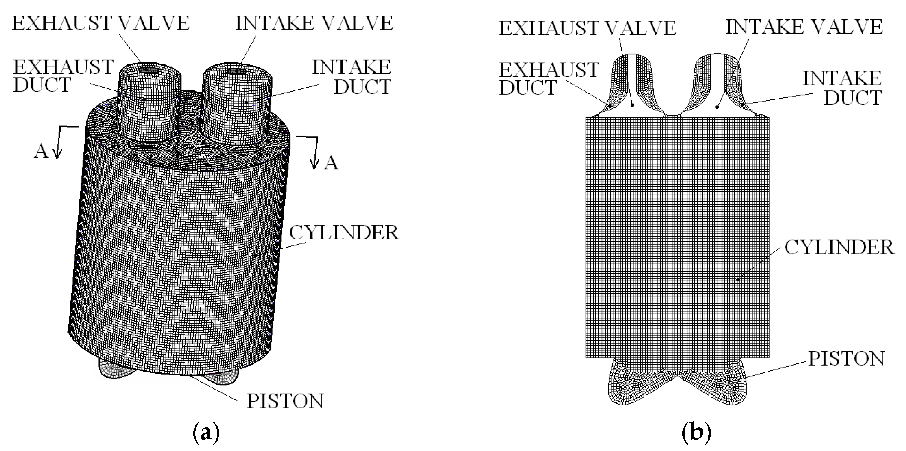
Figure 1. Computational mesh at bottom dead center. (a) Tri-dimensional view; (b) A-A section.
Jmse 10 00043 g001
Figure 2. In-cylinder pressure.
Jmse 10 00043 g002
Figure 3. Emissions and consumption.
Jmse 10 00043 g003
Figure 4. NO emissions against the power contribution from diesel fuel.
Jmse 10 00043 g004
Figure 5. In-cylinder average temperature under 100% and 50% power contribution from diesel fuel.
Jmse 10 00043 g005
Figure 6. CO emissions against the power contribution from diesel fuel.
Jmse 10 00043 g006
Figure 7. HC emissions against the power contribution from diesel fuel.
Jmse 10 00043 g007
Figure 8. CO2 emissions against the power contribution from diesel fuel.
Jmse 10 00043 g008
Figure 9. Thermodynamic and ammonia utilization efficiencies against the power contribution from diesel fuel.
Jmse 10 00043 g009
Figure 10. In-cylinder pressure under 100% and 50% power contribution from diesel fuel.
Jmse 10 00043 g010
Figure 11. NO, N2O, and NH3 emissions against the NH3/NOi ratio.
Jmse 10 00043 g011
Table 1. Engine characteristics.
ParameterValue
Power (kW)320
Speed (rpm)1500
Compression ratio13.5:1
Injection pressure (bar)220
Publisher’s Note: MDPI stays neutral with regard to jurisdictional claims in published maps and institutional affiliations.