Article

Numerical Investigation on Air Film Fusion of Pressure-Equalizing Exhaust around Shoulder Ventilation of Submarine-Launched Vehicle

1
School of Marine Science and Technology, Northwestern Polytechnical University, Xi’an 710072, China
2
Key Laboratory of Unmanned Underwater Projectile, Northwestern Polytechnical University, Xi’an 710072, China
*
Author to whom correspondence should be addressed.
J. Mar. Sci. Eng. 2022, 10(1), 39; https://doi.org/10.3390/jmse10010039
Submission received: 19 November 2021 / Revised: 15 December 2021 / Accepted: 17 December 2021 / Published: 31 December 2021
(This article belongs to the Special Issue Computational Fluid Mechanics)

Abstract

:
In order to study the influence of pressure-equalizing exhaust at the shoulder of a submarine-launched vehicle on the surface hydrodynamic characteristics, this paper establishes a numerical calculation method based on the VOF multiphase flow model, the standard RNG turbulence model and the overset mesh technology; the method compares the fusion characteristics of the air film at the shoulder of the underwater vehicle, as well as the distribution of surface pressure along the vehicle’s axial direction. The results show that the approximate isobaric zone derived from air film fusion can greatly improve the hydrodynamic characteristics of the vehicle, and the number of venting holes determines the circumferential fusion time of the air film. The greater the number of venting holes, the sooner circumferential fusion starts.

1. Introduction

In recent years, launch modes relying on underwater launch platforms have received increasing attention from various countries for their high stealth, long endurance, and high hitting accuracy. However, the progress of related research and testing has not been smooth, mainly due to the lack of systematic and reliable knowledge of the hydrodynamic load problem when the vehicle is not in the water.
During the movement of an underwater vertically launched vehicle, its structure is completely closed. When the vehicle is constantly close to the free liquid surface, the hydrostatic pressure of the external environment decreases sharply; because of the closeness, once the load of internal pressure exceeds the safety margin of the structure design, the vehicle will be damaged.
The vertical launch process of a submarine-launched vehicle in the water can be roughly divided into three stages: the barrel-out stage, the free navigation stage, and the water-out stage [1]. During the barrel-out stage, the vehicle’s energy is gas at high temperature and high pressure, and its speed is increasing; at the same time, cavitation occurs and develops quickly in the low-pressure area at the shoulder of the vehicle. In the free navigation phase, the vehicle is approaching the water surface at decreasing speed. Subsequently, the back jet causes cavitation bubbles to gradually fall off from the end. During the water-out stage, the fluid medium undergoes a sudden change, and the cavitation is continuously collapsed by the interference of the liquid surface. The unsteady, high-frequency, transient-impact load directly acts on the surface of the vehicle [2], which will affect the movement posture and surface of the vehicle. The structure has a serious impact.
In view of the impact load of the vehicle in the process of entering the water, scholars at home and abroad have carried out a series of numerical simulations and experimental testing research and have achieved diverse results. In 1945, Reichardt [3] proposed active ventilated cavitation technology. Later, Knapp et al. [4] directly demonstrated the feasibility of forming cavitation through ventilation technology. Zhang Naimin et al. [5] established a theoretical calculation model of porous exhaust bubble morphology based on the principle of independent cavitation expansion. Ma Guihui et al. [6] studied the effects of single-row exhaust and double-row exhaust combined on the body-fitted air film around the flow field during the vertical water discharge process of the vehicle. Huang Biao [7] carried out research on the dynamic characteristics of unsteady cavitation fluid of a rotating body in a closed water tunnel. Sun Tiezhi [8] carried out research on the influence of the ventilation position on the hydrodynamic characteristics of the submarine-launched vehicle by solving the RANS equation of the mixed medium based on the homogeneous balance flow theory. Gaoshan et al. [9] carried out a refined study on the water exit process of a three-dimensional double-shot salvo based on the VOF multiphase flow model and dynamic mesh technology. Chen Fu et al. [10] simulated the underwater vertical motion process of a vehicle with isobaric exhaust, and analyzed the effect of the exhaust angle on the unsteady development process of the isobaric film and the flow field characteristics of the flow around the vehicle. Bao Wenchun et al. [11] used the VOF multiphase flow model and dynamic grid technology to simulate the bubble development process and pressure distribution on the surface of an underwater launch vehicle. Zhang Ke et al. [12] conducted a numerical study on the exhaust process of an underwater launch vehicle based on the VOF multiphase flow model, and analyzed the development and evolution of cavitation shapes during the navigation and exit stages of the vehicle. Kang Yazhuo et al. [13] simulated the launch process of the vehicle based on the dynamic grid technology and the VOF multiphase flow model, and finally summarized the evolution of bubbles during the whole process of the vertical launch of the vehicle. Yan Guojun et al. [14] obtained the distribution characteristics of the flow field and the pressure on the outer surface of the vehicle through the coupling calculation of the multiphase flow field and the ballistic of the vehicle during the water exit process of a submarine-launched vehicle. Liu Junjun [15] studied and analyzed the influence of various parameters such as the gas pressure, launch speed, and inclination angle of the vehicle on the water outflow of the vehicle. Wang Kelin [16] combined experiments and simulations to study the two-phase flow problem of the double-hole jet flow field under the conditions of multiple flow field parameters and structural parameters. Li Renfeng et al. [17] conducted numerical simulations on the exit and flow field of missiles at different launch speeds. They found that the lateral force produced by the pressure difference between the front and back surfaces of the missile is the reason for the deflection. Zhang Zhao [18] constructed a hybrid mathematical model of the dynamics of underwater-launching high-speed vehicles, and used this model to simulate the dynamics of underwater-launching high-speed vehicles. Based on the RANS equation, Wu Yuyan [19] analyzed the action mechanism of the development of the air mass at the mouth of the launching tube, the internal pressure of the launching tube, and the evolution of the gas–liquid two-phase flow field when the underwater vertically launched vehicle exits the tube. Sun Longquan et al. [20] studied the mechanism of opening a small annular groove at the bottom of the exhaust ring to promote the circumferential fusion of bubbles. They carried out research on the fusion of bubbles by the annular groove under various working conditions and found that the groove can effectively improve the circumferential fusion of the air film. Qiu Yang [21] conducted a numerical simulation study of the multiphase cavitation flow generated by the exhaust gas from the interior cavity of the vehicle, and studied the effect of the exhaust cavitation on the underwater launch process. Duan Lei et al. [22] combined experimental and numerical calculation methods to study the ventilating cavitation flow field around the rotating body. Ren Zeyu et al. [23] used a new type of experimental platform to conduct underwater vertical launch experiments and study the influence of the cavitation number and Froude number on the development and evolution of bubbles. Zhang Subin et al. [24] used numerical simulation methods to study the cavitation flow during the underwater vertical launch of a vehicle. Recently, great progress has been made in the research of cavitation flow of underwater vertically launched vehicles; however, most of them study supercavitating flow at a method of interface capture. Scholars rarely study the evolution process of local cavitation in ventilation and the influence of local cavitation on the hydrodynamic characteristics of the surface of the vehicle.
The shoulder venting technique can effectively improve the hydrodynamic properties of the vehicle surface. In the initial stage of exhaust, bubbles are attached to the outer surface of the vehicle in a bundle. With continuous movement, the bubbles develop, mix, fuse, and finally fall off, especially when the exhaust bubbles fuse into a large bubble, which can greatly improve the force characteristics of the navigation body and improve the stability of the navigation body’s underwater ballistics, as the interior of the bubbles is an approximately isobaric zone.
The hydrodynamic load of high-speed vehicles is the most important basic issue in the underwater vertical launch process; in addition, the stability of cavitation and the characteristics of the collapse load are important objects via which to study this problem. Carrying out a simulation study on the cavitation fusion characteristics of the underwater vehicle shoulder in the circumferential exhaust process can more clearly elucidate the mechanism of the cavitation fusion, which is useful for optimizing the surface structure of the vehicle. It has very important significance to improve the water characteristics and motion stability of the vehicle.
In this paper, based on the VOF multiphase flow model, the overset mesh technique is used to study the air film fusion characteristics of a submerged vehicle. The structure of this paper is as follows: the second part describes the numerical method; the numerical calculation model is established in the third part; the fourth part analyzes the results of the simulation; and the fifth presents the conclusions drawn from the study.

2. Numerical Calculation Method

2.1. Governing Equation

The basic governing equations describing the multiphase flow of underwater vertical launch mainly include the continuity equation, momentum equation, and energy conservation equation. The basic form of the equations is as follows:
Continuity equation:
ρ m t + x i ρ m u i = 0
Momentum equation:
t ρ m u j + x i ρ m u i u j = ρ m x i + ρ g i + x i μ m + μ t u i x j + u i x i
Energy equation:
t ρ m T + x i ρ m u i T = x i k i c p T x j + S T

2.2. Turbulence Equation

In this paper, the RNG model is used for simulation calculation. The turbulence equations are as follows:
ρ D k D t = x i α k μ e f f k x i + G k + G b ρ ε Y M
ρ D ε D t = x i α ε μ e f f ε x i + C 1 ε ε k G k + C 3 ε G b C 2 ε ρ ε 2 k R

2.3. Multiphase Flow Model

This paper uses the VOF multiphase flow model; an equation regarding the phase volume fraction can be established, based on the continuity equation and momentum equation of the mixed phase:
α t + α U = 0
The solution of the equation can be divided into the following situations:
When α = 0, it means that the phase fluid does not exist in the unit;
When 0 < α < 1, it means that the unit contains the interface of this phase fluid and other phase fluids;
When α = 1, it means that the unit contains only the fluid of this phase.

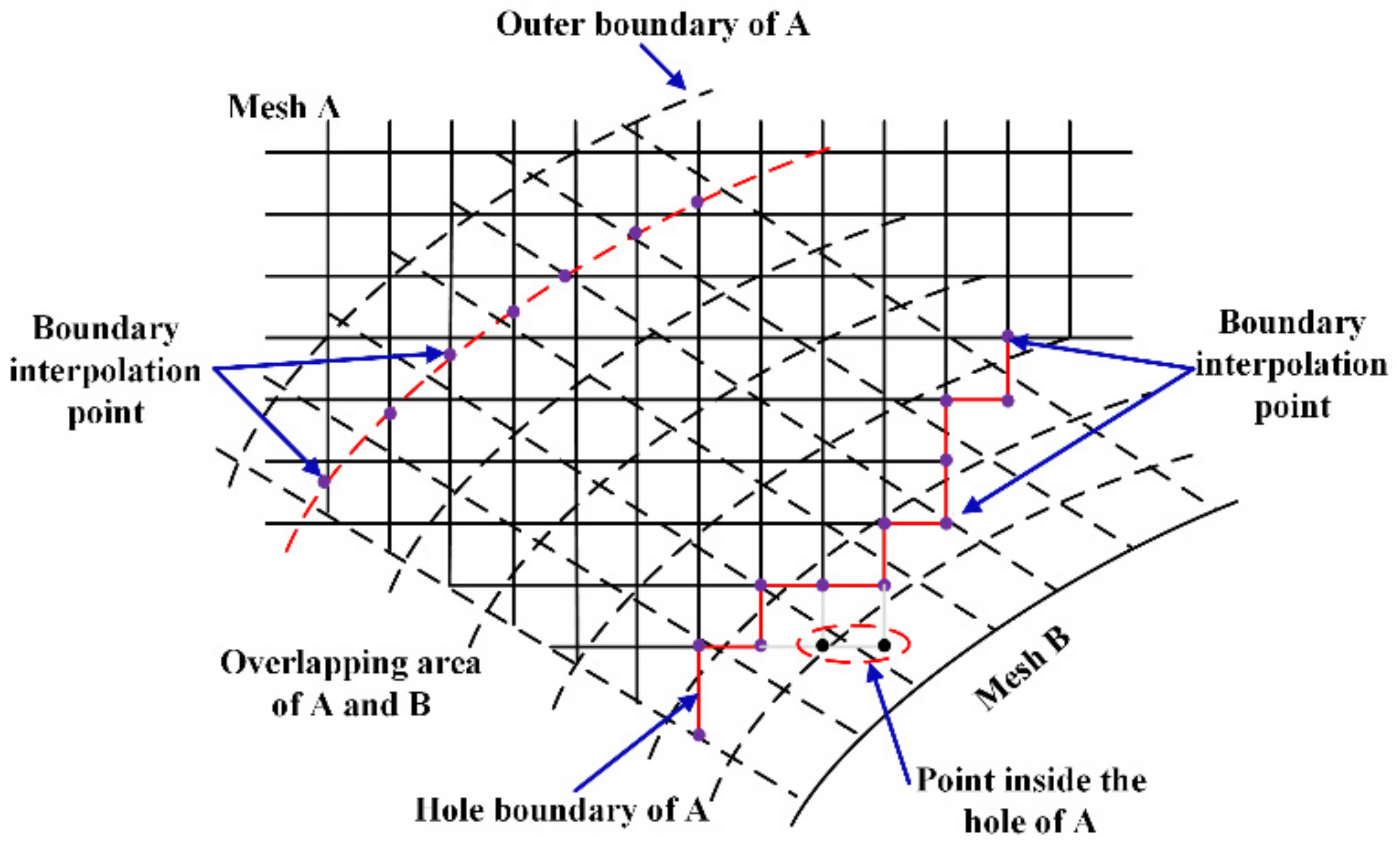
2.4. Overset Meshing

As shown in Figure 1 and Figure 2, the basic idea of the overset meshing technique is to use the sub-domain mesh to interpolate in the overlapping area, and then achieve the effect of real-time transmission of flow field information. There are three types of points in the overset mesh: in-cavity points, computational points, and interpolation points. The in-cavity points are not involved in the flow field calculation, while the computational points are, and the interpolation points are used for the transmission of flow field information. In this study, the computational domain is divided into a background domain and an overlap domain, and the overset mesh is a combination of the background-region mesh and the overlap-region mesh, which overlap in space but are not connected and exist independently of each other.

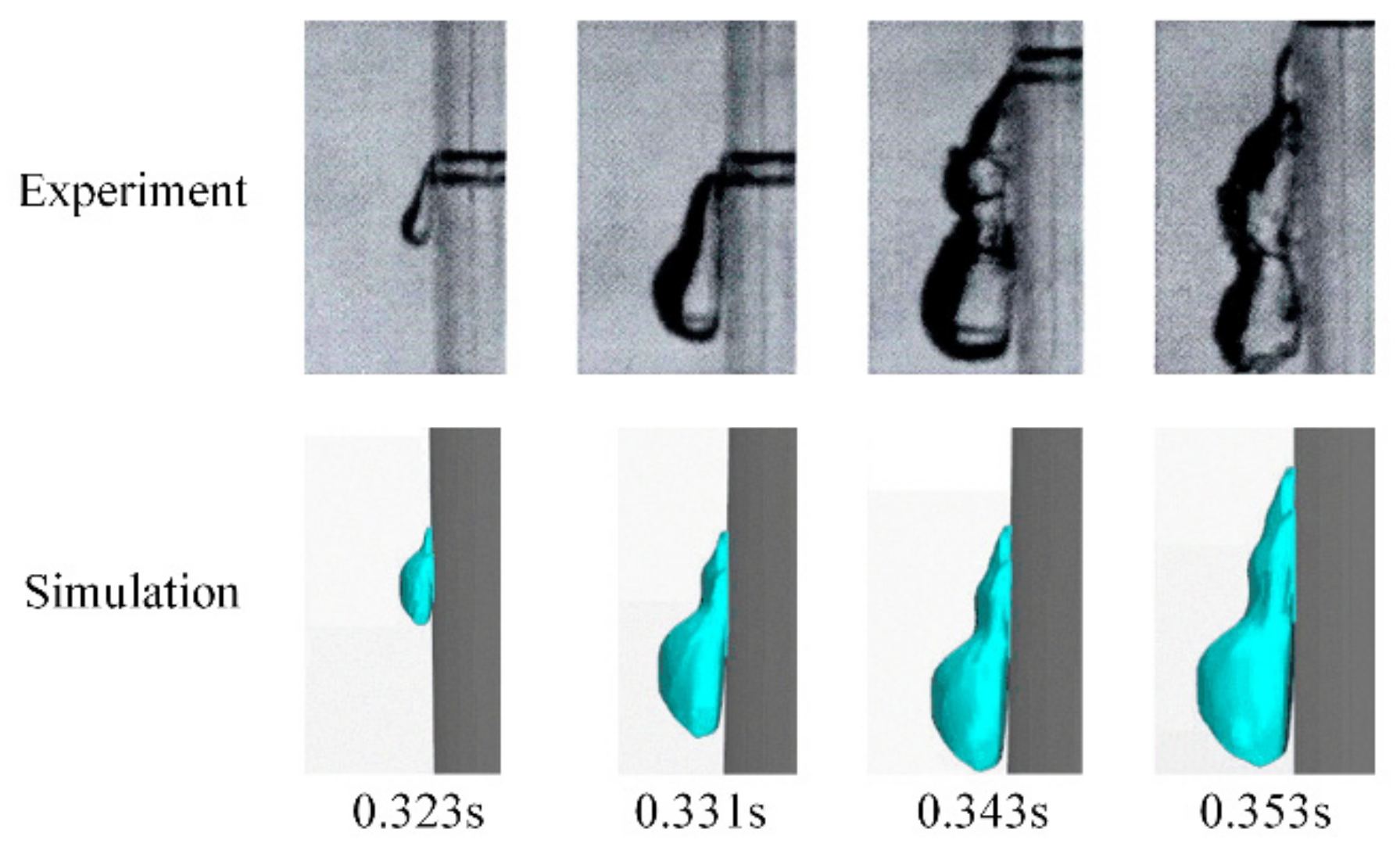
2.5. Numerical Method Verification

In order to verify the effectiveness of the numerical algorithm in this paper, experimental data from the literature [25] are used. The experimental model uses a semi-cylindrical shell with a size of 150 mm × 100 mm × 120 mm (diameter × height × shell thickness), and the speed is 1.2 m/s. The boundary conditions and meshing are shown in Figure 3 and Figure 4.
As shown in Figure 5, we used high-speed cameras to capture the growth process of a bubble in the experiment. From the comparison of the maximum thickness of the bubble, it can be found that the bubble has approximately the same shape, with a trapezoid on the top and a spherical shape on the bottom. Since the surface of the cylinder is set as a non-slip wall and there is no contact angle during the numerical calculation, the results of the simulation are somewhat different from the experimental observations, but they are generally close.
Table 1 and Table 2 show the comparison of the length and width of the air film at different times. The maximum error between the experiment and the numerical calculation is 7.14% and 9.37%, and the error is within the acceptable range, so this research method can be considered effective in studying the size of the bubble.

3. Numerical Calculation Model

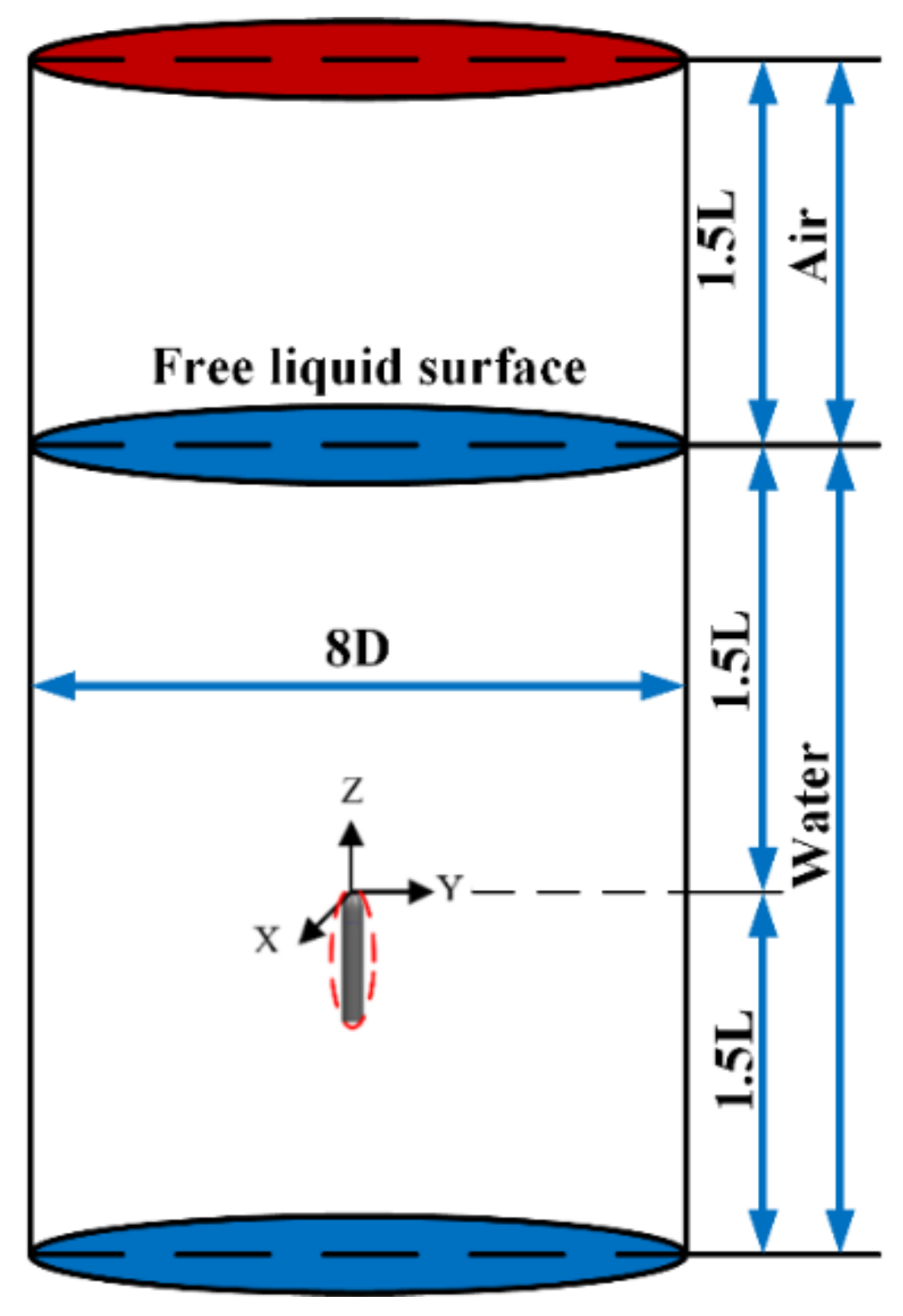
3.1. The Establishment of the Geometric Model

We establish a scaled model of a vehicle with exhaust. As shown in Figure 6, the diameter of the vehicle (D) is 40 mm, the length (L) is 230 mm, and the venting hole’s diameter (d) is 0.6 mm.

3.2. Computational Domain and Boundary Condition Division
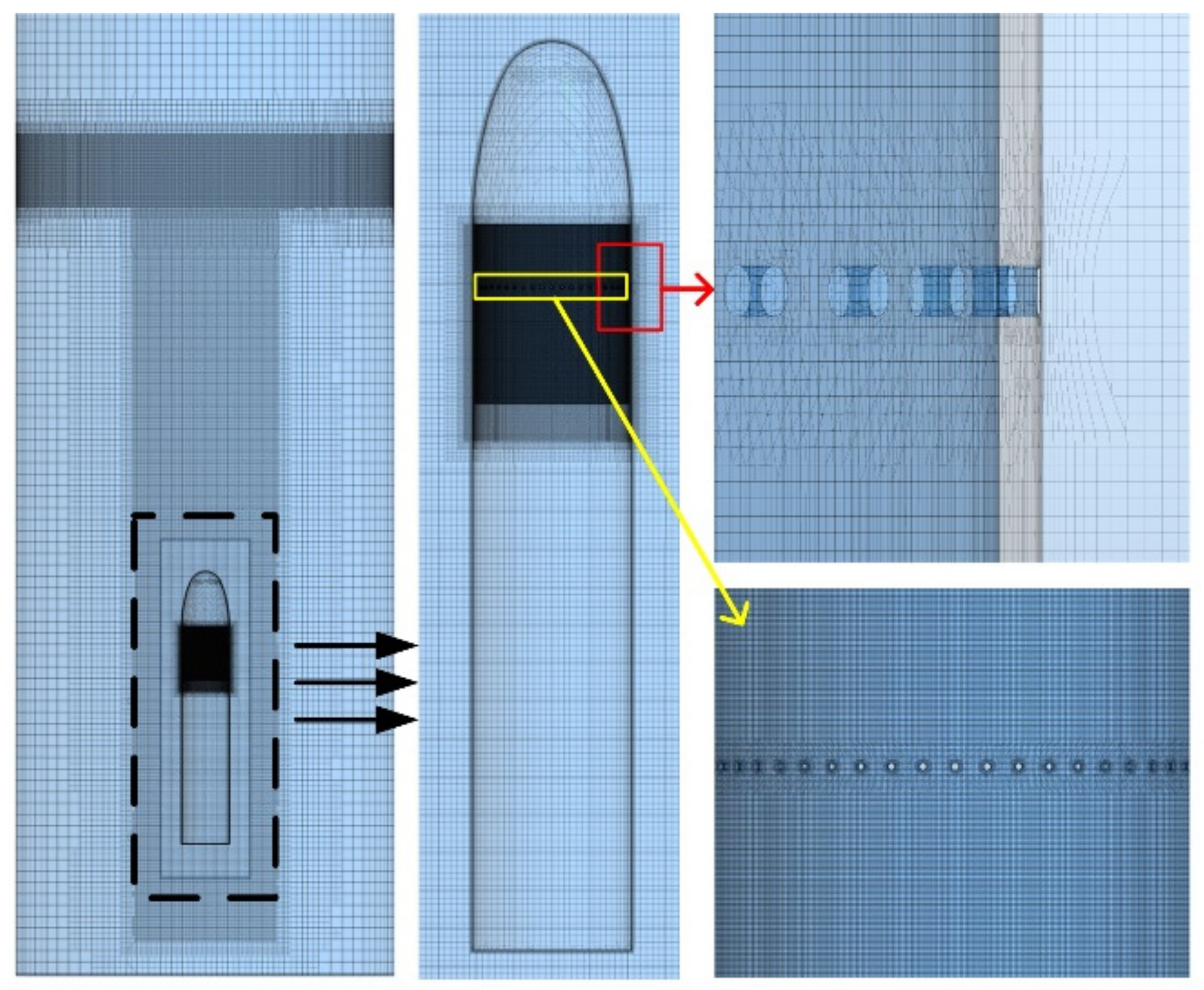
As shown in Figure 7 and Figure 8, the computational domain is divided into a background domain and an overlapping domain. The top of the background domain is the pressure outlet, and the vehicle part of the overlap domain is the overset mesh. All other surfaces are non-slip wall, except for the symmetry plane.
The notations used in this paper are as follows: density of water ρ w , body diameter D, length L, velocity v , time T et al. In order to facilitate the research and analysis, the physical quantities of pressure, time, cavity length, and cavity diameter are treated as dimensionless in Table 3:

3.3. Meshing

As shown in Figure 9, the STAR-CCM+ software is used for meshing. In order to ensure the symmetry of the initial bubble as much as possible, the background mesh and the sub-domain mesh are trimmed volume mesh.
It is necessary to refine the mesh near the motion area of the vehicle and the surface of the water. In addition, in order to reduce the workload and improve the calculation efficiency, we carried out research on the half-mode. The number of meshes in the background domain is around 4.2 million, and that in the sub-domain is around 5.3 million, which meet the calculation requirements of the overset mesh while ensuring calculation accuracy.

3.4. Mesh Independence Verification

In order to verify the influence of the number of grids on the simulation results, we analyzed two different numbers of numerical grids under the first layer height of 0.05 mm. Based on the grid independence approach, coarse grids N c o a r s e = 9 . 5 M and fine grids N f i n e = 14 . 3 M are generated. The grid convergence index (GCI) is used for reporting.
The error of coarse grid is defined as:
E c o a r s e = r p ε 1 r p
ε = f 2 f 1
r = ( N f i n e N c o a r s e ) 1 / d
In this study, f 1 and f 2 represent the minimum dimensionless pressure on the surface of the vehicle on the coarse and fine grids, p is the formal order of accuracy of the algorithm ( p = 2 ), r is the refinement factor between the coarse and fine mesh, and is the dimension of the simulation. The GCI of the coarse grid is defined as:
G C I c o a r s e = F s E c o a r s e
where F s is the safety factor and, in this study, F s = 3 .
In this study, the minimum dimensionless pressure on the surface of vehicle is used for the irrelevant verification of the different grid numbers. The calculation results are shown in Table 4. From Table 4, the calculation results show that the results of the two kinds of grids are similar, and the GCI of the coarse mesh result is within 2%, which meets the calculation requirements.

4. Analysis of Numerical Results

4.1. Analysis of Air Film Fusion Characteristics

Figure 10 shows the fusion process of the air film when the speed of the vehicle is 3.71 m/s, the number of venting holes in a single row is 50, and the diameter is 0.6 mm.
As shown in the Figure 11 and Figure 12, the evolution process of the air film can be roughly divided into three stages: the initial growth stage, the mixing and fusion stage, and the late stage of air film fusion.
In the initial stage, the vehicle leaves the launch tube and moves to the water surface; the external hydrostatic pressure in the area where the venting holes are located decreases continuously, resulting in the ideal gas in the shoulder cavity being discharged from the venting holes. As for the air film, the upper part is elongated and the lower part becomes spherical. It is obvious that multiple rows of air film with a bundle shape are attached to the surface of the vehicle side-by-side.
In the mixing and fusion stage, the hydrostatic pressure decreases faster, and the pressure difference between the inside and outside of the cavity increases continuously. At the same time, the gas flow rate of the venting holes increases, and the initial side-by-side bundle-shaped air film expands significantly in both axial and circumferential directions under the supplement of sufficient high-pressure gas; the shape of the air film gradually becomes strip-like, completely covering the area below the venting holes.
In the late stage of fusion, the fused air film continues to develop down to the bottom of the vehicle to cover the surface below the shoulder and eventually develops from a strip-like to sheet-like structure. When the head of the vehicle reaches the free liquid surface, the air film covering the surface of the vehicle begins to fall off, and, finally, the vehicle is completely out of the water.

4.2. Research on the Characteristics of Surface Pressure of Vehicle

In order to study the influence of the air film on the surface pressure characteristics of the vehicle, as shown in Figure 13, the pressure distribution on the axial centerline of the vehicle’s surface with or without venting holes was examined.
From the distribution of the graph in Figure 14, it can be seen that the existence of venting holes will only affect the area covered by the air film, while the pressure distribution in other areas on the surface of the vehicle is approximately the same. The fusion of the air film causes a low-pressure area at the shoulder of the vehicle and a peak in pressure at the end of the film. The pressure fluctuation at the rear of the vehicle is due to the fusion of the air film wrapped in the upper region of the center of mass, while the lower region of the center of mass is not completely covered and the bubble is partially dislodged.
It can be seen from Figure 15, during the movement of the vehicle, the peak pressure appears at the very front of the head, while a low-pressure region appears in the shoulder region as well as near the tail. The appearance of low pressure in the region of the shoulder comes from the generation of the air film near the venting holes, and the low pressure in the region of the tail is due to the flow separation of the fluid in the tail of the vehicle. The pressure cloud map near the venting hole shows that the top of the hole is a high-pressure area, and the pressure decreases along the incoming flow direction to be similar to that around the hole. In the Figure 16, from the cross-sectional pressure distribution, the pressure increases gradually along the radial direction, with the air film as the center. The generation of the air film makes the pressure near it lower than the local hydrostatic pressure, so it can well improve the flow field environment around the vehicle.
As time goes on, the vehicle keeps moving upward, the depth of water decreases gradually, and the pressure of the local flow field also decreases. The low-pressure area at the shoulder expands continuously, while the high-pressure area at the head decreases gradually. In the movement to T = 80 ms, the high pressure in the head completely disappears; the reason for this is that the head of the vehicle has been out of the water so is no longer subject to water pressure but standard pressure. After the head of vehicle is out of the water, the low-pressure area in the shoulder completely disappears; the reason for this is that the air film passes through the water surface, and surrounding media from water to air. The internal equilibrium of the attached bubble is broken due to the pressure difference between the internal and external areas and the complex force acting on the surface of the vehicle, and it eventually collapses.

4.3. Effect of the Number of Holes on Air Film Fusion and Pressure Distribution

In this section, the evolution process of the bubble and the pressure distribution characteristics of the double row of holes with the spacing of 6 mm, 7 mm, 8 mm, 9 mm, and 10 mm at the velocity of 3.71 m/s is considered.
In order to study the effect of double-row pores on the evolution of the vacuole morphology, the length and thickness of the vacuole were measured at different moments, and the evolution is shown in Figure 17.
As can be seen from Figure 18 and Figure 19, with the development of time, the maximum length of the air film grows linearly as a whole, and the maximum diameter grows faster in the first period, slows down in the later period, and finally stays the same. At the same time, the larger the spacing between the double-row holes, the larger the maximum length of the air film and the smaller the maximum diameter. As for the structure, the exhaust area of the double-row holes is twice as large as that of the single-row holes, and the larger exhaust area determines the higher expansion rate of the air film. Due to the same volume of gas in the cavity, the excessive consumption of gas in the initial stage also determines the slow rate in the later stage, and the maximum diameter growth rate slows down gradually, as seen in the graph.
In order to demonstrate the difference in the effect of the air film on the surface pressure distribution of the vehicle in different cases, the distribution of the model surface pressure along the axial direction is given in Figure 20.
In the early stage of exhaust, the double-row hole solution is significantly better than the single-row hole solution for the expansion rate of the approximate isobaric zone in the axial direction; meanwhile, in the late stage of exhaust, the growth rate of the approximate isobaric zone with larger axial dimensions slows down, and the magnitude of the strong inverse pressure gradient caused by the hysteresis effect at the rear of the air film decreases. Generally speaking, axial coverage is better than that of the single-row hole. In the early stage of exhaust, an approximate isobaric zone with a small axial pressure gradient is formed between the two rows of holes, which can effectively improve the hydrodynamic characteristics of the vehicle. In addition, the bubbles produced by the first row of holes cover the surface of the second row; compared with the single row, the surface of the second row is no longer a high-speed transverse water flow, but a low-pressure, low-density gas, and the shearing effect of the axial incoming flow on the second row is weaker, which is more conducive to the fusion of the air film.

5. Conclusions

Based on the VOF multiphase flow theory, standard RNG turbulence model, and overset mesh technology, this paper establishes a numerical calculation model for the pressure equalization exhaust of a submarine-launched vehicle and simulates the evolution and development of the air film on the shoulder of the vehicle under different exhaust conditions. The conclusions are as follows:
(1)
Pressure-equalizing exhaust is the passive exhaust process of gas under the joint action of the incoming shear force and the hydrostatic pressure drop of the holes. The gas morphology of the holes develops from a bundle-like to a strip-like structure, and finally develops into a sheet-like structure and achieves complete fusion.
(2)
The fusion film forms an isobaric zone in the coverage area, which reduces the amplitude of the surface pressure of the vehicle and effectively improves the hydrodynamic characteristics of the vehicle.
(3)
Compared with the single row of holes, the double row has a greater speed of axial advance, radial expansion, and circumferential fusion, and the approximate isobaric zone inside the film also develops faster, so the double row is more conducive to improving the hydrodynamic characteristics of the vehicle.

Author Contributions

Conceptualization and methodology, all authors; design of simulation ideas, J.R. and S.G.; setting of simulation cases, sorting and analysis of data, visualization of results and writing-original draft, J.R.; writing-review and editing, Y.S. and J.R.; management of project, supporting of funding and equipment, Y.S. and G.P. All authors have read and agreed to the published version of the manuscript.

Funding

The research was supported by the National Natural Science Foundation of China (Grant No. 52171324) and the Fundamental Research Funds for the Central Universities (Grant No. 3102019JC006).

Data Availability Statement

All data and models generated or used during the research period appear in the submitted manuscript.

Acknowledgments

We are grateful to the National Natural Science Foundation of China (Grant No. 52171324) and the Fundamental Research Funds for the Central Universities (Grant No. 3102019JC006) for their financial support of our research work.

Conflicts of Interest

The authors have no conflict of interest and unanimously agree to submit the manuscript to the journal.

References

  1. Wang, Y.W.; Huang, C.G. Research progress on hydrodynamics of high-speed vehicles in the underwater launching process. J. Adv. Mech. 2018, 48, 259–298. [Google Scholar]
  2. Wang, Y.W.; Huang, C.G.; Du, T.Z.; Fang, X.; Liang, N.G. Mechanism analysis about cavitation collapse load of underwater vehicles in a vertical launching process. J. Chin. J. Theoretical Appl. Mech. 2012, 44, 39–48. [Google Scholar]
  3. Reichardt, H. The Laws of Cavitation Bubbles at Axially Symmetrical Bodies in A Flow. Kais. Wilhelm Inst. Stromungsforsch. 1945, 766, 322–326. [Google Scholar]
  4. Knapp, R.T.; Daily, J.W.; Hammitt, F.G. Cavitation. J. Fluid Mech. 1972, 54, 189–191. [Google Scholar]
  5. Zhang, N.M.; Zhao, Y.; Wei, H.P.; Cheng, S.H. Research on fusion characteristics of porous exhaust bubbles in underwater vertical launch vehicle. J. Ship Mech. 2018, 22, 135–143. [Google Scholar]
  6. Ma, G.H.; Chen, F.; Yu, J.Y. Research on the effect of the number of stomata on the flow around the exhausted vehicle. J. Eng. Thermophys. 2018, 39, 1945–1951. [Google Scholar]
  7. Huang, B.; Wang, G.Y.; Quan, X.B.; Zhang, M.D. Study on the unsteady cavitating flow dynamic characteristics around a 0-caliber ogive revolution body. J. Exp. Fluid Mech. 2011, 25, 22–28. [Google Scholar]
  8. Sun, T.Z.; Wei, Y.J.; Wang, C.; Cao, W. Analysis of the effect of ventilation positions on hydrodynamic characteristics of submarine-launched vehicle. J. Beijing Univ. Aeronaut. Astronaut. 2013, 39, 1303–1308. [Google Scholar]
  9. Gao, S.; Pan, G. Characteristics Research on Unsteady Flow Field during Salvo of Submarine-launched Vehicles. J. Digital Ocean. Underw. Warf. 2020, 3, 271–275. [Google Scholar]
  10. Chen, F.; Ma, G.H.; Cheng, S.H.; Jiang, S. Effect of Straight or Inclined Hole Exhaust on Flow around Underwater Vehicle: Part 1-Flow Field Structure. J. Eng. Thermophys. 2016, 37, 507–513. [Google Scholar]
  11. Bao, W.C.; Quan, X.B.; Wei, H.P. Numerical Simulation on the Flow Dynamics of Underwater Vehicle Launching with Exhaust. J. Missiles Space Vehicles. 2014, 21, 14–18. [Google Scholar]
  12. Zhang, K.; Liu, G.T. Three-dimensional Numerical Simulation on Flow Field of Underwater Vehicle Launching with Air Exhaust. In Proceedings of the the 14th National Hydrodynamics Conference and the 28th National Hydrodynamics Conference, Changchun, China, 8 August 2017; Volume 7, pp. 100–106. Available online: https://kns.cnki.net/kcms/detail/detail.aspx?dbcode=CPFD&dbname=CPFDLAST2017&filename=SLDX201708002012&uniplatform=NZKPT&v=tDXf9Ep8FtMAzLJpFwtYF_hgiCscmTTdN_mIZgdWM4h_5ieTIFLA8YBa_eFtqbK4YrvN9iPVPZA%3d (accessed on 25 November 2021).
  13. Kang, Y.Z.; Wang, C.C.; Wu, Q.; Huang, B.; Kong, D.C. Numerical Simulation on Vertical Launch of Vehicle with Pressure-equalizing. In Proceedings of the the 29th National Hydrodynamics Symposium, Zhenjiang, China, 25 August 2018; Volume 6, pp. 187–192. Available online: https://kns.cnki.net/kcms/detail/detail.aspx?dbcode=CPFD&dbname=CPFDLAST2019&filename=SLDX201808001021&uniplatform=NZKPT&v=fat6wacm5-FMkZ1XaeObTnEuVKxgflFJv0_6-zTbTLak7UbHZvDUAo3vKQSQP36189W24fZQy6M%3d (accessed on 25 November 2021).
  14. Yan, G.J.; Liang, X.X.; Zhang, J.; Quan, X.B.; Wei, H.P. Investigation on the Vertical Launching Process of the Underwater Vehicle by Couple the Flow Field and the Hydro-ballistics. J. Energy Conserv. Technol. 2019, 37, 307–312. [Google Scholar]
  15. Liu, J.J. The Research of the Head-Ventilated Projectile on the Process of Water-Exit. Ph.D. Thesis, Harbin Engineering University, Harbin, China, 2020. [Google Scholar]
  16. Wang, K.L. Research on Gas-liquid Multiphase Flow Characteristics of Pinhole Jet Flow Field. Ph.D. Thesis, Harbin Institute of Technology, Harbin, China, 2019. [Google Scholar]
  17. Li, R.F.; Hu, X.L.; Wang, Z.H.; Le, G.G. Effect of Flow Speed on Tube-exit of Submarine-launched Missile. J. Fire Control Command Control. 2019, 44, 98–101, 106. [Google Scholar]
  18. Zhang, Z. Study on Dynamic Simulation of Submarine High Speed Voyage Based on Mixed Mathematical Model. J. Ship Sci. Technol. 2020, 42, 31–33. [Google Scholar]
  19. Wu, Y.Y. Analysis of Flow Field Characteristics of Submarine Launched Vehicle during Launching Out of Cylinder. Ph.D. Thesis, Harbin Institute of Technology, Harbin, China, 2020. [Google Scholar]
  20. Sun, L.Q.; Yan, H.; Ma, G.H.; Zhao, J.P. Analysis of the Promoting Effect of Annular Groove on the Coalescence of Ventilated Cavity. J. Chin. J. Theor. Appl. Mech. 2021, 53, 386–394. [Google Scholar]
  21. Qiu, Y. Numerical Simulation Research on the Influence of Cavity Exhaust to the Process of Vehicle Underwater Launch. Ph.D. Thesis, Harbin Institute of Technology, Harbin, China, 2013. [Google Scholar]
  22. Duan, L.; Wang, G.Y.; Fu, X.N. Research on Unsteady Characteristics of Ventilated Cavitating Flow in the Form of Gas-leakage by Toroidal Vortex. Acta Armam. 2014, 35, 712–718. [Google Scholar]
  23. Ren, Z.Y.; Sun, L.Q.; Li, Z.P.; Xiao, W. Experimental Study on the Cavitation Development and Collapse Characteristics of Underwater Vehicle. J. Astronaut. Syst. Eng. Technol. 2021, 5, 42–49. [Google Scholar]
  24. Zhang, S.B.; Lu, C.J.; Chen, X. Investigation of Ventilated Cavity Shapes of a High-speed Underwater Vehicle. J. Shanghai Jiaotong Univ. 2012, 46, 329–334. [Google Scholar]
  25. Wei, Q.D. Research on Experimental Characteristics of Underwater Porous Exhaust. Ph.D. Thesis, Harbin Engineering University, Harbin, China, 2016. [Google Scholar]
Figure 1. Schematic of overset mesh.
Jmse 10 00039 g001
Figure 2. Process flow chart of overset mesh.
Jmse 10 00039 g002
Figure 3. Boundary conditions.
Jmse 10 00039 g003
Figure 4. Meshing.
Figure 4. Meshing.
Jmse 10 00039 g004
Figure 5. Comparison between numerical and experimental results of cavity.
Jmse 10 00039 g005
Figure 6. Geometric model.
Jmse 10 00039 g006
Figure 7. Computational domain.
Jmse 10 00039 g007
Figure 8. Boundary conditions.
Jmse 10 00039 g008
Figure 9. Schematic of numerical mesh.
Jmse 10 00039 g009
Figure 10. Evolution of exhaust air film at different times.
Jmse 10 00039 g010
Figure 11. Three stages of air film development.
Jmse 10 00039 g011
Figure 12. Distribution of phase volume fraction.
Jmse 10 00039 g012
Figure 13. Distribution of surface pressure along vehicle.
Jmse 10 00039 g013
Figure 14. Schematic of the exterior of vehicle.
Jmse 10 00039 g014
Figure 15. Pressure distribution in the computational domain at different moments.
Jmse 10 00039 g015
Figure 16. Distribution of pressure near the air film.
Jmse 10 00039 g016
Figure 17. Three-dimensional shape of the air film at different times.
Jmse 10 00039 g017
Figure 18. Evolution of length.
Jmse 10 00039 g018
Figure 19. Evolution of diameter.
Jmse 10 00039 g019
Figure 20. Distribution of surface pressure along vehicle’s axial direction.
Jmse 10 00039 g020
Table 1. Comparison of bubble length in experiment and CFD.
Time0.0670.3230.3310.3530.3570.3600.3630.366
CFD1318233438424546
Exp1419243640444648
Error7.14%5.26%4.2%5.55%5%4.55%2.17%4.2%
Table 2. Comparison of bubble width in experiment and CFD.
Time0.0670.3230.3310.3530.3570.3600.3630.366
CFD35.57.51010111111
Exp3681111121212
Error08.33%9.37%9.09%9.09%9.09%9.17%9.17%
Table 3. Non-dimensionalization of physical quantities.
Pressure TimeCavity LengthCavity Diameter
p = p 1 / 2 ρ w v 2 T = T D / v L = L L D = D D
Table 4. Analysis of physic coefficients under different grid numbers.
Physic CoefficientsCoarseFineEcoarseGCIcoarse
Min dimensionless pressure0.4960.4970.00421.26%
Publisher’s Note: MDPI stays neutral with regard to jurisdictional claims in published maps and institutional affiliations.

