Article

Theoretical Investigations of the Headland Turning Agility of a Trailed Asymmetric Implement-and-Tractor Aggregate

1
Department of Mechanics, Faculty of Construction and Design, National University of Life and Environmental Sciences of Ukraine, 03041 Kyiv, Ukraine
2
Department of Agricultural and Environmental Science, University of Bari Aldo Moro, 70126 Bari, Italy
3
Department of Agricultural Machinery, University of Ruse “Angel Kanchev”, Studentska 8, POB7017 Ruse, Bulgaria
4
Faculty of Engineering, Latvia University of Life Sciences and Technologies, LV-2130 Jelgava, Latvia
*
Author to whom correspondence should be addressed.
Agriculture 2019, 9(10), 224; https://doi.org/10.3390/agriculture9100224
Submission received: 27 August 2019 / Revised: 13 October 2019 / Accepted: 14 October 2019 / Published: 16 October 2019

Abstract

:
Turning time occupies a significant part of the operations carried out by implement-and-tractor aggregates, especially in fields with short runs. Incorrectly executed turns increase the width of the turning strips, significantly increasing the idle path of the implement-and-tractor aggregate, with negative effect on its efficiency. The objective of this paper was to theoretically analyse the turning agility of an asymmetric implement-and-tractor aggregate, taking into account its forward speed and design parameters. Considering a trailed asymmetric swath reaper and tractor aggregate, the obtained equations allowed a numerical simulation in order to evaluate the headland turning agility of this implement-and-tractor aggregate. The minimal radii of the trailed asymmetric swath reaper and tractor aggregate are, respectively, 8.33 m for right-side turn and 4.90 m for left-side turn. Furthermore, the optimal angle between the longitudinal axis of the aggregating tractor and the hitch bar of the trailed asymmetric implement exists only in the case of left-side U-turns and its value is 1.12 rad (64°). It is not possible to cover right-side U-turns or both right- and left-side pear-shaped loop-turn in the optimal mode.

1. Introduction

The growing world population and the consequent pressure on resources are leading to adoption of more efficient technical solutions in agriculture using automation and information technology [1,2,3,4]. As an example of these new challenges, the automatic driving systems that use differential global positioning systems (D-GPS) are becoming the standard for large agricultural machines [5,6]. However, agricultural operations are performed in fields of different shapes and sizes with work or productive phases and transitional or non-productive phases, such as turning at the headlands [7,8]. Headland movements of agricultural machines are important due to their influence on the operational efficiency [9]. As already known, the automatic driving systems are commonly able to parallel track, but headland manoeuvring is not usually comprised. The turning process at the end of the field’s track was analysed both agronomically and economically, highlighting its great impact on the overall operation [10]. Therefore, the headland width and the relative driving time are parameters which should be minimised above all for fields with short runs, where turning time requires a significant portion of the operation of the implement-and-tractor aggregate [11,12]. Incorrectly executed turns increase the width of the turning strips, significantly enlarging the idle path of the implement-and-tractor aggregate, with a negative effect on its efficiency [13]. The ability of an implement-and-tractor aggregate to perform manoeuvres along paths of a certain curvature can be considered as its turning agility, that is to say that the greater the curvature of the indicated path (or the smaller its radius of curvature), the higher the turning agility of the implement-and-tractor aggregate [14].
The car theory developed at the present time distinguishes three cases concerning turning agility: neutral turning agility occurs if the curvature of the path does not depend on the car speed, excessive turning agility occurs if the curvature of the path increases with the car speed and insufficient turning agility occurs if the curvature of the path decreases with the car speed increasing [15,16].
Obviously, in the theory of the turning agility concerning a car, its forward speed plays a dominant role, as it is usually quite high. Conversely, in the theory of the turning agility regarding the agricultural implement-and-tractor units, speed of motion also plays an important role, but is less dominant than in the theory of the car steering [17]. There is no doubt that the turning agility of an agricultural implement-and-tractor aggregate is affected by its forward speed, but this is less dominant than car turning agility. The most important task in the study of the turning agility of implement-and-tractor aggregates is the evaluation of the parameters that most affect the process, and establishment of their effect (through analytical equations) on the execution of the turning [18,19]. The turning radius depends mainly only on the parameters of the tractor in the case of trailed implements [17], even if the turning radius of the aggregate is significantly increased when aggregating trailed implements [20,21]. Furthermore, several types of trailed implements that are commonly used in agricultural work are arranged asymmetrically with respect to the tractor. The operative conditions of these trailed asymmetric implement-and-tractor aggregates have peculiarities regarding both their stability of motion and their implementation of the headland manoeuvres, also considering the difference between left-side and right-side turns [22,23,24]. A correctly substantiated headland turning agility of an asymmetric implement-and-tractor aggregate will essentially increase its efficiency, especially in fields with short runs, by reducing the length of its idle passes on the turns [25,26,27].
On this basis, the study aimed to theoretically investigate the turning agility of an asymmetric implement-and-tractor aggregate, taking into account its forward speed and design parameters. Furthermore, considering the obtained equations, a numerical simulation was performed to assess the kinematic behaviour of a trailed asymmetric swath reaper and tractor aggregate during the headland turning.

2. Materials and Methods

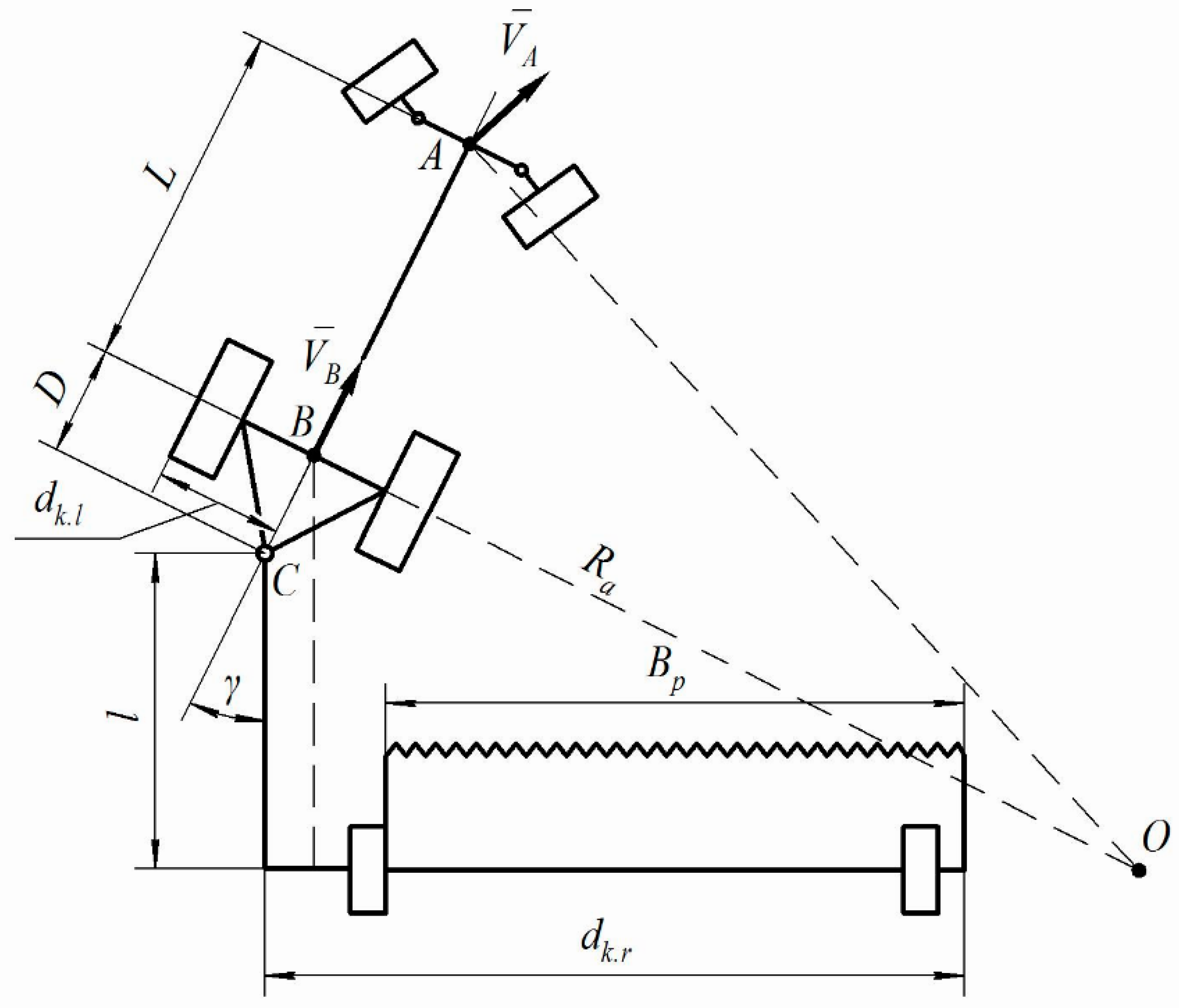
2.1. Theoretical Considerations

Figure 1 shows a trailed asymmetric swath reaper–tractor aggregate when it executes a right-side turn. The characteristic points of the given implement-and-tractor unit are indicated on the layout scheme as follows: (i) the point A is the middle of the axle of the front-driven wheels of the aggregating tractor; (ii) the point B is the middle of the axle of its rear driving wheels; (iii) point C is the connection point of the aggregated swath reaper.
Furthermore, the following linear and angular dimensions are represented on the layout scheme of the turn: L is the wheelbase of the aggregating tractor, m; D is the distance from the axis of the rear axle of the tractor to the connection point C of the swath reaper, m; BP is the working width of the swath reaper, m; dk.l is the kinematic width of the aggregate to the left of the longitudinal axis of the tractor (the distance from the outer plane of the rear driving wheel to the longitudinal axis of the tractor), m; dk.r is the kinematic width of the aggregate to the right of the longitudinal axis of the tractor (the total width of the swath reaper), m; γ is the angle between the longitudinal axis of the aggregating tractor and the hitch bar of the trailed swath reaper, rad.
Taking into account that the aggregating wheeled tractor is positioned in the turning layout scheme (Figure 1) in the position that corresponds to entering the turn, with its front-driven wheels turned in the direction of the turn at certain angles, in a first approximation it is then assumed that the turning angles of the driven wheels are equal to each other. In this case, the direction of the velocity vectors of the driven wheels coincide and it is possible to apply the velocity vector V A ¯ of the front-driven wheels of the aggregating tractor at point A (the centre of the axle of the driven wheels). The velocity vector V B ¯ of the rear driving wheels of the tractor is applied at the centre of its rear axle, at the point B, and its direction coincides with the longitudinal axis of the tractor.
The position of the instant centre of rotation of the aggregate is at the intersection of the perpendiculars drawn to the velocity vectors V A ¯ and V B ¯ from points A and B, respectively. Thus, the obtained point O is the centre of a circle with radius RA along which point A is moving, and simultaneously the centre of a circle with radius RB along which point B is moving. In addition, the velocity vectors V A ¯ and V B ¯ are the peripheral velocities of points A and B, respectively, around the point O. Considering all the points of segment AB, the radius RB is the shortest and is taken as the turning radius of the examined implement-and-tractor aggregate, denoted Ra. Consequently, it appears that precisely the displacement of point B along the circle with radius Ra is the turn of this implement-and-tractor aggregate around the turning centre, i.e., around point O. However, the actual turning of this asymmetric harvesting implement-and-tractor aggregate is affected by the operative conditions of the front-driven and rear driving wheels, which are subject to skidding and drifting in various directions, have contact with the non-uniform surface of the soil and are affected by different vertical loads. Therefore, these factors can have a significant impact not only on the position of the radius of rotation of the unit, but also on its magnitude. Furthermore, a possible increase in the curvature radius Ra of the path of the aggregating wheeled tractor during the turn occurs mainly as a result of the lateral drift of the front-driven wheels. The lateral drift of the rear driving wheels of the tractor and the supporting wheels of the trailed swath reaper has been neglected in the present study. It has also been supposed that during turning of the implement-and-tractor aggregate all the wheels roll without skidding, and that their instantaneous turning centres coincide.

2.2. Data for Numerical Analysis

A numerical simulation was carried out to obtain the values of the characteristics concerning the headland turning agility of an asymmetric implement-and-tractor aggregate consisting of a 1.4 class MTZ-80 (60 kW) wheeled tractor and a ZhVP-6 trailed reaping machine (Figure 2). This aggregate’s great efficiency means that it is widely used in two-phase grain harvesting in Ukraine. The main technical features of the tractor are as follows: rated power 60 kW; fuel consumption at rated power, 220 g kWh−1; wheelbase, 2450 mm; overall length, 3930 mm; operating weight without ballast, 3900 kg. The main technical features of the reaping machine are as follows: weight, 1545 kg; productivity, 2.8 ha∙h−1; capture width, 4900 mm.
The following design values of this asymmetric harvesting implement-and-tractor aggregate were used for the numerical simulation (Figure 1): l = 3.4 m; D = 1.0 m; L = 2.37 m; dk.l = 1.0 m; dk.r = 7.0 m; e = 2.5 m; BP = 6.0 m. Furthermore, the following design maximum value of angles γ , have been taken into account, respectively:
  • maximum value of angle γ for right-side turn γ max.r = 0.54 rad (31°);
  • maximum value of angle γ for left-side turn and γ max.l = 0.94 rad (54°).

3. Results and Discussion

3.1. Evaluation of Ramin

The accepted basic design parameters of the asymmetric swath reaper and tractor aggregate and the constructed layout scheme of its turning (Figure 1) were used to analytically determine the value of its turning radius Ra. From the geometric analysis of the turning scheme (Figure 1), the following can be obtained:
R a · s i n γ = l + D · c o s γ
Therefore, the turning radius Ra of the implement-and-tractor aggregate can be calculated:
R a = l + D · c o s γ s i n γ
with 0 < γ γ m a x .
On the other hand, one of the parameters for the estimation of the static turning agility of an implement-and-tractor aggregate is the minimal radius Ramin of its turn. Obviously, the minimal turning radius Ramin is reached at the maximal value of the angle γ , i.e., on condition γ = γ m a x . In this case, considering Equation (2) it follows that:
R a m i n = l + D · c o s γ m a x s i n γ m a x

3.2. Evaluation of the Turning Agility Indicator K and Kp

Analytical determination of the minimum turning radius Ramin of the asymmetric harvesting machine-and-tractor aggregate cannot serve as the only and exhaustive parameter in the kinematics of a curvilinear movement of this aggregate [9,10].
The transition from a rectilinear movement of the aggregate, i.e., with radius R = ∞, to a curve with a constant minimum radius R = Ramin cannot occur immediately. An extra period of time elapses between the moment the aggregating tractor enters the turn and the moment corresponding to movement along the arc with radius Ramin [6,11]. This extra period of time is affected by: (i) the design of the entire machine-and-tractor aggregate; (ii) the steering peculiarities of the aggregating tractor; (iii) the personal qualities of the tractor driver, and so on. Furthermore, during this time the trajectory of the aggregating tractor is a clothoid, which allows a smooth transition from zero curvature to the curvature corresponding to radius Ramin [14]. As is already known, the curvature is the reciprocal of the turning radius. Of course, there are two extra times, so-called “into the turn” and “out of the turn”, respectively. In addition to the minimum turning radius Ramin concerning the movement of an asymmetric machine-and-tractor, it is also necessary to determine other important indicators, including the so-called agility index K of the implement-and-tractor aggregate, which characterises the agility of the aggregate in shifting from a rectilinear to a curved movement, and vice versa [10,11]. Agility index K is largely affected by the type of the tractor, its speed of movement and the skill of its operator. In this regard, although not easily measurable, it is obvious that a well-trained driver can turn the aggregate more easily than a novice driver. Due to high turning speeds, the following expression is often used [11] to evaluate K for aggregates with wheeled tractors:
K = L · V t r . t s ω
where: L is the wheelbase of the aggregating tractor;
Vtr.ts is the forward speed of the aggregate on the turning strip, m s−1;
ω is the average turning angular velocity of the steering wheel of the tractor, s−1.
Based on the analysis of Equation (4), the turning agility of an aggregate largely depends not only on the type of the tractor and its design parameters (L), but also on its forward speed and the skill of the machine operator ( V t r . t s ω ). Furthermore, considering a tractor with wheelbase L, the higher the speed of the tractor V t r . t s , the greater the value of K because the tractor will cover a greater distance to achieve the same radius; conversely, the greater the angular velocity of rotation ω , that is the higher the agility of the aggregate, the smaller the value of K with this wheelbase L [11]. According to this, for each tractor with wheelbase L, it is appropriate to consider and analyse as the agility index the following K P :
K P = V t r . t s ω
Previous studies have established that the following basic requirements should be observed for the choice of the mode of movement of an implement-and-tractor aggregate on a turning strip [23,24]:
(a)
the average speed of the implement-and-tractor aggregate on the turning strip should be equal to the maximum allowed for the effective conditions of the operation (for most agricultural machine-and-tractor aggregates, not exceeding 2.5 m s−1, with the minimum value no less than 1 m s-1);
(b)
the average angular velocity of the turn of the aggregating tractor’s driven wheels should be 0.22 s−1; furthermore, the optimal turning angular velocity of the steering wheel of the tractor performed by the driver can be carried out in the range ω = 0.20–0.22 rad s−1, and the minimum frequency is ω = 0.10 rad s−1.
Considering the above conditions, the corresponding K P values can be evaluated using Equation (5):
  • K p   m i n = 1/0.22 = 4.5 m rad−1;
  • K p   o p t = 2.5/0.22 = 11.4 m rad−1;
  • K p   m a x = 2.5/0.1 = 25.0 m rad−1.
Figure 3 reports the forward speed Vtr.ts of the implement-and-tractor aggregate on the turning strip as affected by the angular speed of rotation ω of the tractor steering wheels for different values of K p . K p   m i n and K p   m a x are points in the graph, whereas the rectilinear path corresponding to the optimal value of the index ( K p   o p t ) was obtained considering the Equation:
V t r . t s = K p   o p t · ω
with 0.10 ω 0.22 .
Furthermore, the forward speed of the implement-and-tractor aggregate on the turning strip should not exceed 2.5 m s−1, while the angular turn velocity of the driven wheels of the aggregating tractor should be less than 0.22 rad s−1 in order to perform the turn in the optimal mode with a higher value K p (Figure 3).

3.3. Evaluation of Ropt and γ o p t

For each type of turn of the implement-and-tractor aggregate it is possible to introduce the optimal radius Ropt corresponding to the lowest turning length, given by [25]:
R o p t = L · V t r . t s 2 · ω · ε m a x = L · K p 2 · ε m a x
where: L is the wheelbase of the tractor, m;
εmax is the maximal angle of the turn of the aggregate at the time when it completes the “entrance into the turn”, rad.
As a rule, the optimal radius Ropt corresponds to the lowest turning radius required to achieve the given turning agility of the implement-and-tractor aggregate. If the lowest radius Ramin is greater than Ropt, then a circular trajectory with radius Ramin will occur, and the turn will be longer than the shortest turn. If the lowest allowed turning radius Ramin is smaller than Ropt, then it will be impossible to use it during normal operation [18]. Therefore, the best solution of this issue is:
R o p t = R a m i n
The turning radius R o p t of the asymmetric harvesting machine-and-tractor aggregate ensures the necessary conditions to prevent damage to the hitch and drive mechanisms, which inevitably approach during this manoeuvre, and to guarantee that there is no lateral skidding of the support wheels, and so on [21].
Turning agility K P concerning the examined asymmetric swath reaper and tractor aggregate can be evaluated by rearranging the Equations (3), (5) and (7) and then the optimal turn is achieved by moving on the headland in a certain way that corresponds to the indicator K P calculated as follows:
K P = V t r . t s ω = 2 · ε m a x · ( l + D · c o s γ m a x ) 2 L · s i n 2 γ m a x
Taking into account that the turning agility index K P is determined by the design and kinematic parameters of the implement-and-tractor aggregate, a definite value of angle γ corresponds to its optimal value K P o p t . From the expression (9) the following is obtained after transformations:
γ o p t = a r c o s b + b 2 4 · a · c 2 a
where:
b = 4 · ε m a x · D · l
a = K P o p t · L + 2 · ε m a x · D 2
c = K P o p t · L + 2 · ε m a x · l 2
Equation (10) makes it possible to determine γopt for each particular implement-and-tractor aggregate performing a kind of turning. When this γopt is compared with the actual highest possible (design) value of angle γ m a x , turning agility of the implement-and-tractor aggregate is insufficient if γ m a x < γ o p t , whereas turning agility is excessive if γ m a x > γ o p t .
Equation (9) highlights that it is necessary to keep in the set ratio the forward speed V t r . t s of the implement-and-tractor aggregate and the angular speed of rotation ω of the tractor steering wheels in order to obtain a good turning agility index K P . This is rather difficult under normal operations conditions and tractors should therefore be fitted with electronic devices allowing automatic control of the preset value K P during turns made by the implement-and-tractor aggregate.

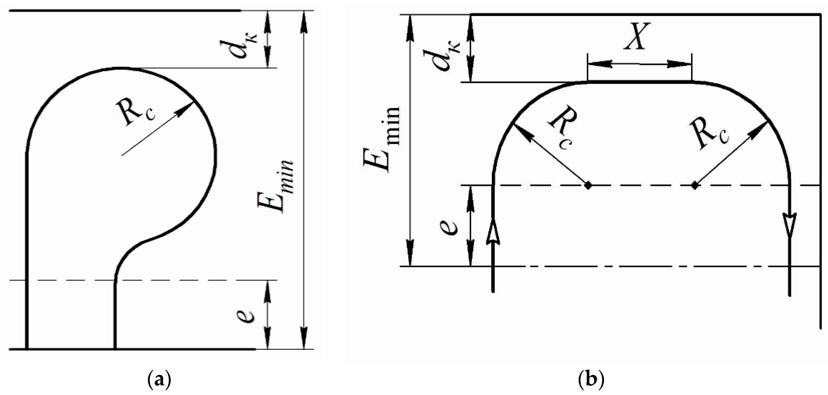
3.4. Evaluation of Emin

Finally, another important parameter of any implement-and-tractor aggregate is the lowest headland width Emin for the turning manoeuvre. As known, different continuous-curvature paths are used in headlands, adjusted to the farmer’s requirements [14]. The movement of the harvesting implement-and-tractor aggregates on the turning strip usually consists of a combination of two kinds of turns: a “pear-shaped loop-turn” and a “U-turn” with a straight strip (Figure 4) [9].
For both these types of turns, the value of the indicator Emin is determined by the following [21]:
E m i n = R c + d K + e
where: Rc is the conditional turning radius of the implement-and-tractor aggregate, m;
dK is the kinematic width of the aggregate, i.e., the distance from the longitudinal axis of the aggregate to the most distant operating tool to the left or to the right, m;
e is the running distance of the aggregate onto the headland before the above-mentioned manoeuvres, m.
The conditional turning radius Rc is defined as the radius at which the implement-and-tractor aggregate would carry out a turn only with a circular path, that is without transitional sections of the aggregate entering into a turn and leaving it [17]; this can be determined by using the following Equation:
R c = R a m i n + L · K P π · R a m i n
Therefore, the conditional turning radius R c   of the implement-and-tractor aggregate takes into account its speed, manoeuvrability and design parameters.
Initially, the harvesting tractor-implement will perform pear-shaped loop turns, and continue to perform them until the following condition is met:
B p 2 R c
After condition (16) is fulfilled, the harvester unit will start to perform U-turns with straight strip. Considering both kinds of turns: pear-shaped loop-turn and “U-turn” with straight strips, Equation (14) combined with Equation (15) highlights that the minimum headland width Emin for turns of the aggregate depends significantly on its turning agility K P .

3.5. Numerical Results

With reference to the examined asymmetric swath reaper and tractor aggregate, the lowest radii corresponding, respectively, to turn left and right have been calculated using Equation (3):
  • minimum radius pertinent to the right-side turn R a m i n . r =   8.33 m;
  • minimum radius pertinent to the left-side turn R a m i n . l =   4.90 m.
Furthermore, the following values have been considered for each kind of turn [27]:
  • ε m a x = π 4 for U-turn with a straight strip
  • ε m a x = π 2 for pear-shaped loop-turn.
Therefore, the optimal radii Ropt, which allow the lowest turning length, are assessed using Equation (6):
  • R o p t =   2.90 m corresponding to ε m a x = π 2 ;
  • R o p t =   4.94 m corresponding to ε m a x = π 4 .
Furthermore, for each kind of turn (pear-shaped loop-turn and U-turn with a straight strip), the indicator K P has been evaluated for the right- and left-side turns using Equation (9) (Figure 5). The obtained values of indicators K P are significantly different each other and highlight the unequal behaviour of the asymmetric swath reaper and tractor aggregate on the turn if compared with the optimal Kp opt = 11.4. In particular, the headland turning agility K P concerning U-turns with a straight strip is quite similar to Kp opt in the event of left-side turns (−0.15%), whereas K P is 180% greater that Kp opt for right-side turns. Conversely, the headland turning agility K P concerning pear-shaped loop-turns never allows optimal conditions because K P is 190% greater that Kp opt for left-side turns and 716% for right-side turns. According to these results, except for the left-side U-turns, the examined asymmetric swath reaper and tractor aggregate has a limited turning agility, or more precisely, right-side U-turns and the right-and-left-side pear-shaped loop-turns are practically impossible in the optimal mode (Figure 5). This result can also be obtained by assessing the optimal angle γ o p t , using Equation (10) and the optimal value Kp opt = 11.4. Considering the data pertinent to the examined asymmetric swath reaper and tractor aggregate, the Equation (10) has a real solution (0.93 rad, i.e., 53°) only in the case of U-turns with a straight strip. Therefore, left and right-side pear-shaped loop-turns cannot be executed with an optimal turning agility Kp opt and these turns are certainly wider than the corresponding narrowest turns. Furthermore, the obtained value of γ o p t was compared with the maximum allowed design values of angle γ m a x for the right- and left-side turns respectively, giving these results: (i) γ m a x . r = 31 ° < γ o p t   = 53 ° ; (ii) γ m a x . l = 54 ° γ o p t = 53 ° . In the first case, the width covered by the aggregate will be greater than that the lowest allowed. Conversely, in the second case the turning agility of the implement-and-tractor aggregate occurs in optimal conditions.

4. Conclusions

The headland turning agility of an asymmetric implement-and-tractor aggregate was analysed and, depending on its design parameters, analytical equations were obtained in order to determine the minimal turning radius R a m i n , the value of the optimal angle γ o p t   between the longitudinal axis of the aggregating tractor and the hitch bar of the trailed asymmetric implement, as well as the width required to perform the turn. These equations were then used in a numerical simulation in order to calculate the characteristics values of the characteristics concerning the headland turning agility of an asymmetric swath reaper and tractor aggregate. The minimal radii of this implement-and-tractor aggregate were calculated as 8.33 m for the right-side turn and 4.90 m for the left-side turn, respectively. Furthermore, it was shown that the optimal angle γ o p t exists only in the case of left-side U-turns and that its value is 1.12 rad (64°); conversely, it is not possible to perform right-side U-turns or right-side and left-side pear-shaped loop-turns in the optimal mode.
Finally, the agility index K P must be kept at the established value during the turns made by the implement-and-tractor aggregate. Therefore, tractors should be equipped with suitable devices that can automatically adjust the forward speed of the tractor on the turning strip and/or the average angular velocity of the turn of its driven wheels in order to maintain the K P value stable.

Author Contributions

Conceptualization and Methodology, V.B., S.P., H.B. and S.I.; Formal Analysis, Investigation and data curation, V.B., S.P., H.B. and S.I.; Writing—Original Draft Preparation, V.B., H.B. and S.I.; Writing—Review & Editing, V.B. and S.P.; Supervision, V.B., S.P.

Funding

This research received no external funding.

Acknowledgments

This research did not receive any specific grant from funding agencies in the public, commercial or not-for-profit sectors.

Conflicts of Interest

The authors declare no conflict of interest.

References

  1. Kamilaris, A.; Prenafeta-Boldú, F.X. Deep learning in agriculture: A survey. Comput. Electron. Agric. 2018, 147, 70–90. [Google Scholar] [CrossRef] [Green Version]
  2. Liakos, K.G.; Busato, P.; Moshou, D.; Pearson, S.; Bochtis, D. Machine Learning in Agriculture: A Review. Sensors 2018, 18, 2674. [Google Scholar] [CrossRef] [PubMed]
  3. Manetto, G.; Cerruto, E.; Pascuzzi, S.; Santoro, F. Improvements in citrus packing lines to reduce the mechanical damage to fruit. Chem. Eng. Trans. 2017, 58, 391–396. [Google Scholar]
  4. Jha, K.; Doshi, A.; Patel, P.; Shah, M. A comprehensive review on automation in agriculture using artificial intelligence. Artif. Intell. Agric. 2019, 2, 1–12. [Google Scholar] [CrossRef]
  5. Bulgakov, V.; Pascuzzi, S.; Adamchuk, V.; Kuvachov, V.; Nozdrovicky, L. Theoretical study of transverse offsets of wide span tractor working implements and their influence on damage to row crops. Agriculture 2019, 9, 144. [Google Scholar] [CrossRef]
  6. Huang, P.; Luo, X.; Zhang, Z. Field verification of the autonomous agricultural machine headland turning control method. Int. Agric. Eng. J. 2016, 25, 98–105. [Google Scholar]
  7. Bochtis, D.D.; Griepentrog, H.W.; Vougioukas, S.; Busato, P.; Berruto, R.; Zhou, K. Route planning for orchard operations. Comput. Electron. Agric. 2015, 113, 51–60. [Google Scholar] [CrossRef]
  8. Bochtis, D.D.; Vougioukas, S.G. Minimising the non-working distance travelled by machines operating in a headland field pattern. Biosyst. Eng. 2008, 101, 1–12. [Google Scholar] [CrossRef]
  9. Sabelhaus, D.; Roben, F.; Meyer zu Helligen, L.P.; Schulze Lammers, P. Using continuous-curvature paths to generate feasible headland turn manoeuvres. Biosyst. Eng. 2013, 116, 399–409. [Google Scholar] [CrossRef]
  10. Engelhardt, H. Auswirkungen von Flächengröße und Flächenform auf Wendezeiten, Arbeitserledigung und verfahrenstechnische Maßnahmen im Ackerbau. Ph.D. Thesis, Institut für Landtechnik, Universität Giessen, Giessen, Germany, 2004. [Google Scholar]
  11. Bulgakov, V.; Ivanovs, S.; Adamchuk, V.; Nadykto, V. Theoretical investigation of turning agility of machine and tractor aggregate on basis of ploughing and intertilling wheeled tractor. In Proceedings of the 15th International Scientific Conference: Engineering for Rural Development, Jelgava, Latvia, 25–27 May 2016; Volume 15, pp. 1077–1084. [Google Scholar]
  12. Bulgakov, V.; Pascuzzi, S.; Nadykto, V.; Ivanovs, S. A mathematical model of the plane-parallel movement of an asymmetric machine-and-tractor aggregate. Agriculture (Switz.) 2018, 8, 151. [Google Scholar] [CrossRef]
  13. Gyachev, L. Dynamics of the Machine and Tractor and Automobile Aggregates; A Monograph; Rostov State University: Rostov-on-Don, Russia, 1976; 192p. [Google Scholar]
  14. Backman, J.; Piirainen, P.; Oksanen, T. Smooth turning path generation for agricultural vehicles in headlands. Biosyst. Eng. 2015, 139, 76–86. [Google Scholar] [CrossRef]
  15. Wong, J.Y. Theory of Ground Vehicles; John Wiley & Sons, Inc.: New York, NY, USA, 2001; 558p. [Google Scholar]
  16. Gusjkov, V. Tractors: Theory; Technics: Moscow, Russia, 1988; 376p. [Google Scholar]
  17. Kutjkov, G. Tractors and Cars; Theory and Technological Properties; SpecAgrarian science: Moscow, Russia, 2004; 504p. [Google Scholar]
  18. Bulgakov, V.; Ivanovs, S.; Nadykto, V.; Kuvachov, V.; Masalabov, V. Research on the turning agility of a two-machine aggregate. INMATEH-Agric. Eng. 2018, 54, 139–146. [Google Scholar]
  19. Graf Plessen, M.M.; Bemporad, A. Reference trajectory planning under constraints and path tracking using linear time-varying model predictive control for agricultural machines. Biosyst. Eng. 2017, 153, 28–41. [Google Scholar] [CrossRef]
  20. Bulgakov, V.; Nadykto, V.; Kaletnik, H.; Ivanovs, S. Field experimental investigations of performance-and-technological indicators of operation of swath header asymmetric machine-and-tractor aggregate. In Proceedings of the 17th International Scientific Conference Engineering for Rural Development, Jelgava, Latvia, 23–25 May 2018; Volume 17, pp. 227–233. [Google Scholar]
  21. Bulgakov, V.; Grinik, I.; Lezhenkin, A. Dynamics of the Grain Harvesting Aggregates; Agricultural science: Kiev, Ukraine, 2010; 276p. [Google Scholar]
  22. Bulgakov, V.; Pascuzzi, S.; Santoro, F.; Anifantis, A.S. Mathematical Model of the Plane-Parallel Movement of the Self-Propelled Root-Harvesting Machine. Sustainability 2018, 10, 3614. [Google Scholar] [CrossRef]
  23. Kyurchev, V.M. Mechanical and Technological Foundations of Aggregating Ploughing and Intertilling Tractors; A Monograph; Institute for Agricultural Engineering and Electrification: Glevaha, Ukraine, 2015; 44p. [Google Scholar]
  24. Masalabov, V. Determination of the Turning Mode Indicator of a Two-Machine Seed Machine-and-Tractor Aggregate; Proceedings of Tauria Agrarian University: Melitopol, Ukraine, 2012; Volume 2, pp. 3–7. [Google Scholar]
  25. Nadykto, V. Analysis of the Turning Agility of the Machine and Tractor Aggregates on the Basis of Modular Means of Energy. Sci. Bull. Tavria Univ. Agric. 2005, 29, 28–34. [Google Scholar]
  26. Powell, N.; Boyette, M. Agricultural robotics using a zero turning radius platform. In Proceedings of the ASAE Annual International Meeting, Ottawa, ON, Canada, 1–4 August 2004; pp. 4223–4228. [Google Scholar]
  27. Iofinov, S. A Handbook for the Operation of the Machine-and-Tractor Fleet (Справoчник пo эксплуатации машиннo-трактoрнoгo парка); Agropromizdat: Moscow, Russia, 1986; p. 272. [Google Scholar]
Figure 1. Turning layout of a trailed asymmetric swath reaper–tractor aggregate.
Agriculture 09 00224 g001
Figure 2. The asymmetric harvesting machine-and-tractor aggregate used in the test, consisting of an MTZ-80 wheeled tractor and ZhVP-6 cutter bar.
Agriculture 09 00224 g002
Figure 3. Forward speed Vtr.ts of the implement-and-tractor aggregate on the turning strip as affected by the angular speed of rotation ω of the tractor steering wheel for different values of Kp.
Agriculture 09 00224 g003
Figure 4. Possible asymmetrical turns of a harvesting machine-tractor aggregate on the headland: (a) “pear-shaped loop turn”; (b) “U-turn” with a straight strip.
Agriculture 09 00224 g004
Figure 5. Turning agility of asymmetric implement (swath reaper)–tractor aggregate. Indicator K P   for each kind of turn (pear-shaped loop-turn and U-turn with a straight strip) and for right- and left-side turns, respectively.
Agriculture 09 00224 g005

