Article

A Mathematical Model of the Plane-Parallel Movement of an Asymmetric Machine-and-Tractor Aggregate

1
Department of Mechanics, Faculty of Construction and Design, National University of Life and Environmental Sciences of Ukraine, 03041 Kyiv, Ukraine
2
Department of Agricultural and Environmental Science, University of Bari Aldo Moro, 70124 Bari, Italy
3
Department of Machine Use in Agriculture, Mechanical Engineering Faculty, Tavria State Agrotechnological University of Ukraine, 72310 Melitopol, Ukraine
4
Faculty of Engineering, Latvia University of Agriculture, LV2130 Jelgava, Latvia
*
Author to whom correspondence should be addressed.
Agriculture 2018, 8(10), 151; https://doi.org/10.3390/agriculture8100151
Submission received: 26 July 2018 / Revised: 12 September 2018 / Accepted: 25 September 2018 / Published: 1 October 2018
(This article belongs to the Special Issue Advances in Agriculture Mechanization)

Abstract

:
Technological peculiarities of cultivation and harvesting of some agricultural crops make it necessary to use asymmetric machine-and-tractor aggregates. However, for the time being there is no sufficiently complete, analytical study of the steady movement of such machine-and-tractor aggregates. This necessitates the development of a theory of stable movement of the aggregates which would allow choosing their optimal kinematic and design parameters. On the basis of the results of mathematical simulation, a system of linear differential equations of the second order is obtained describing transverse displacement of the center of masses of the aggregating wheeled tractor and turning of its longitudinal axis of symmetry by some angle around the indicated center of mass, as well as the deviation angle of the rear-trailed harvester from the longitudinal axis of the tractor at any arbitrary moment of time. This system of differential equations can be applied for numerical calculations on the PC, which will make it possible to evaluate the stability of the movement of the asymmetric machine-and-tractor aggregate when it performs the technological process.

1. Introduction

The careful arrangement of agricultural machines is fundamental for both their performance and operators’ safety [1,2]. In this regard, it is worth remembering that several conditions linked to the technical features of the tractors (mass distribution, center of mass location, narrow track and so on), and/or particular operative situations, (soil conformation, high slopes, and so on) may cause their overturn during agricultural operations [3,4]. The combined machine-and-tractor aggregate, too, may produce risk situations during working conditions. Most combined machine-and-tractor aggregates are formed according to classical symmetrical schemes where the agricultural machines, front- and rear-mounted on the aggregating tractors, are arranged symmetrically in relation to the longitudinal axes of symmetry of the source of power, which provides conditions for their steady movement during the execution of one of the technological processes [5,6,7]. However, in some cases it is necessary to aggregate asymmetrically located agricultural machines when the tractor must move across one part of the field but the machine across a part of the field situated from one side (for instance, a harvester, a machine for removing the sugar beet tops, a rotary mower, trailed silage harvesters, and so on) [8,9]. This particular type of asymmetric agricultural unit has an initial instability of movement, since the agricultural machine attached to the rear of the aggregating tractor (for example, a roll cutter) is entirely on one side of the longitudinal axis (axis of symmetry) of the aggregating tractor, which initially causes the turning moment relative to the trailer point to the tractor [10,11]. Furthermore, this turning moment caused by the lateral arrangement of the support elements (support wheels that move along the soft loose soil and, through the load, make a deep groove in it) of the trailed agricultural machine relative to the axis of symmetry of the aggregating tractor and shifted by the technological load during the processing of agricultural material, significant value during the movement of such a machine-tractor unit, always exists [12,13]. In addition, this turning point is the greater, the greater are the forces that arise when the working bodies of an asymmetrically installed agricultural machine interact with the material being processed [14]. In addition, these forces are random functions of many factors, such as variable yield, different type of soil (and, consequently, different bearing capacity), different strength of the cut off array of stems, and so on [15].
Performance of one or another agricultural machine-and-tractor aggregate may be regarded then as its reaction to the incoming, control and perturbing impacts [16]. In this case, the reactions of the machine-and-tractor aggregate to the control impact characterize its controllability, and the reactions to the perturbing impact characterize the stability of its movement [17,18]. Most often, it is considered that the main incoming control impact is the turning angle of the driven wheels of the aggregating tractor. As the incoming perturbing impacts, there are the unfolding moments, various resistance forces, the speed of the working movement of the aggregate, and so on [19]. The main operators for dynamic systems are the transfer functions, the amplitude-frequency, and the phase-frequency response [20,21]. However, to determine them, a system of corresponding differential equations is required which connect the output variables with the incoming impacts, that is, a mathematical model of the investigated process is needed.
There are many investigations devoted to an analytical study of the movement stability of trailed agricultural machines within the structure of various machine-and-tractor aggregates [22,23]. Yet in these and other works, insufficient attention has been paid to the stability of their movement. Particularly this concerns asymmetric machine-and-tractor aggregates when their stability was estimated by the results of static calculations, by determining the deflecting (unfolding) moments of forces. In some other cases, the trailed asymmetric machine is considered separately from the source of power (the tractor) [24,25]. There are analytical studies when the movement of the entire machine-and-tractor aggregate is evaluated only by the movement of the tractor which is under the influence of only one concentrated (often constant by direction) resistance force from the side of the aggregated asymmetric tool. However, the study of the dynamics and stability of the asymmetric machine-and-tractor aggregate will be most accurate in the case when the peculiarities of the design and movement of the aggregating tractor, and the trailed asymmetric agricultural machine are taken into account, including the elastic-damping properties of the tires on the travelling wheels of the tractor, and the resulting deformation of the soil in various directions.
Taking in mind the aforesaid, the aim of the work is the development of a mathematical model of the plane-parallel movement of an asymmetric agricultural machine-and-tractor aggregate, which makes it possible to numerically simulate its kinematic parameters in optimal and/or risk conditions. Finally, the comparison of the theoretically achieved results with experimental data which indicated acceptable coincidence is also reported.

2. Materials and Methods

To develop a mathematical model of the plane-parallel movement of an asymmetric machine-and-tractor aggregate, a wheeled aggregating tractor and a rear-trailed windrower are considered (Figure 1). In addition, the link between the aggregating tractor and the rear-trailed windrower is performed by means of a cylindrical joint. This machine-and-tractor aggregate is asymmetric since the rear-mounted windrower is displaced to the right of the longitudinal axis of the tractor.
Figure 2 reports the equivalent scheme of an asymmetric machine-and-tractor aggregate considering its movement only in a plane, which is parallel to the plane of the field surface First of all, we will construct an equivalent scheme of an asymmetric machine-and-tractor aggregate considering its movement only in a plane that is parallel to the plane of the field surface (Figure 2).
This asymmetric machine-and-tractor aggregate is a complex dynamic system for which the following assumptions are accepted:
The surface of the field across which the particular harvesting aggregate moves is strictly horizontal, and therefore its inclination is neglected;
The wheeled aggregating tractor is a solid body that has a longitudinal plane of symmetry passing through its center of mass;
Fluctuations of the tractive resistance of the trailed windrower have no significant effect on the speed of the forward movement of this aggregate, which is then considered constant in first approximation;
Interaction of the pneumatic tires of the aggregating tractor wheels and the supporting wheels of the trailed windrower with the surface of the soil (in the lateral directions) does not go beyond the limits of the well-known hypothesis of the “lateral drift” of tires;
Because of the small values, the gyroscopic and stabilizing moments of the pneumatic tires of the tractor and windrower wheels are not considered;
The slip angles of the pneumatic tires of the travelling wheels of the aggregating tractor, located on the same geometric axis, as well as the lateral forces acting on them, will be considered sufficiently small;
The turning angles of the left-side and the right-side driven wheels of the aggregating tractor are considered small and equal, taking into account that the basic movement of this harvesting machine-and-tractor aggregate is close to rectilinear, when performing the technological process of cutting grain crops.
Considering the asymmetry of this machine-and-tractor aggregate, its movement in a horizontal plane will initially be unstable. Besides, a hypothesis is advanced about an increase in the moment of the stabilizing movement of the particular asymmetric harvesting aggregate in a horizontal plane, which will be possible due to the installation of the supporting wheels of the aggregated windrower at rational divergence angles.

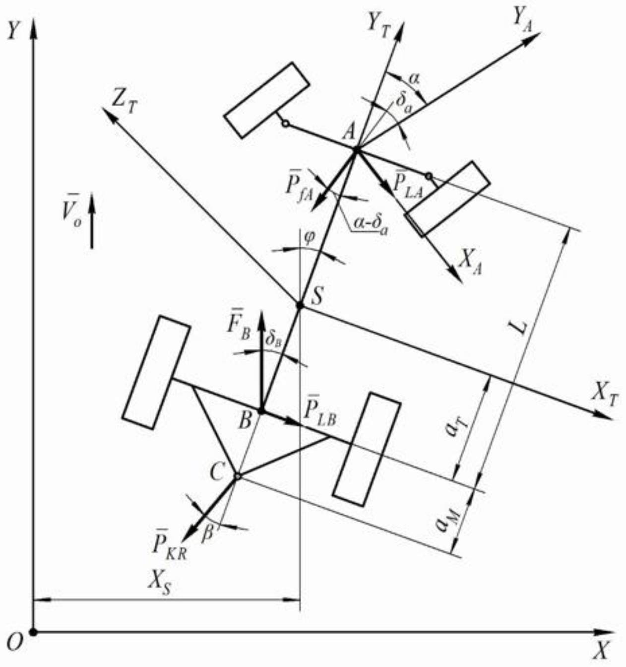
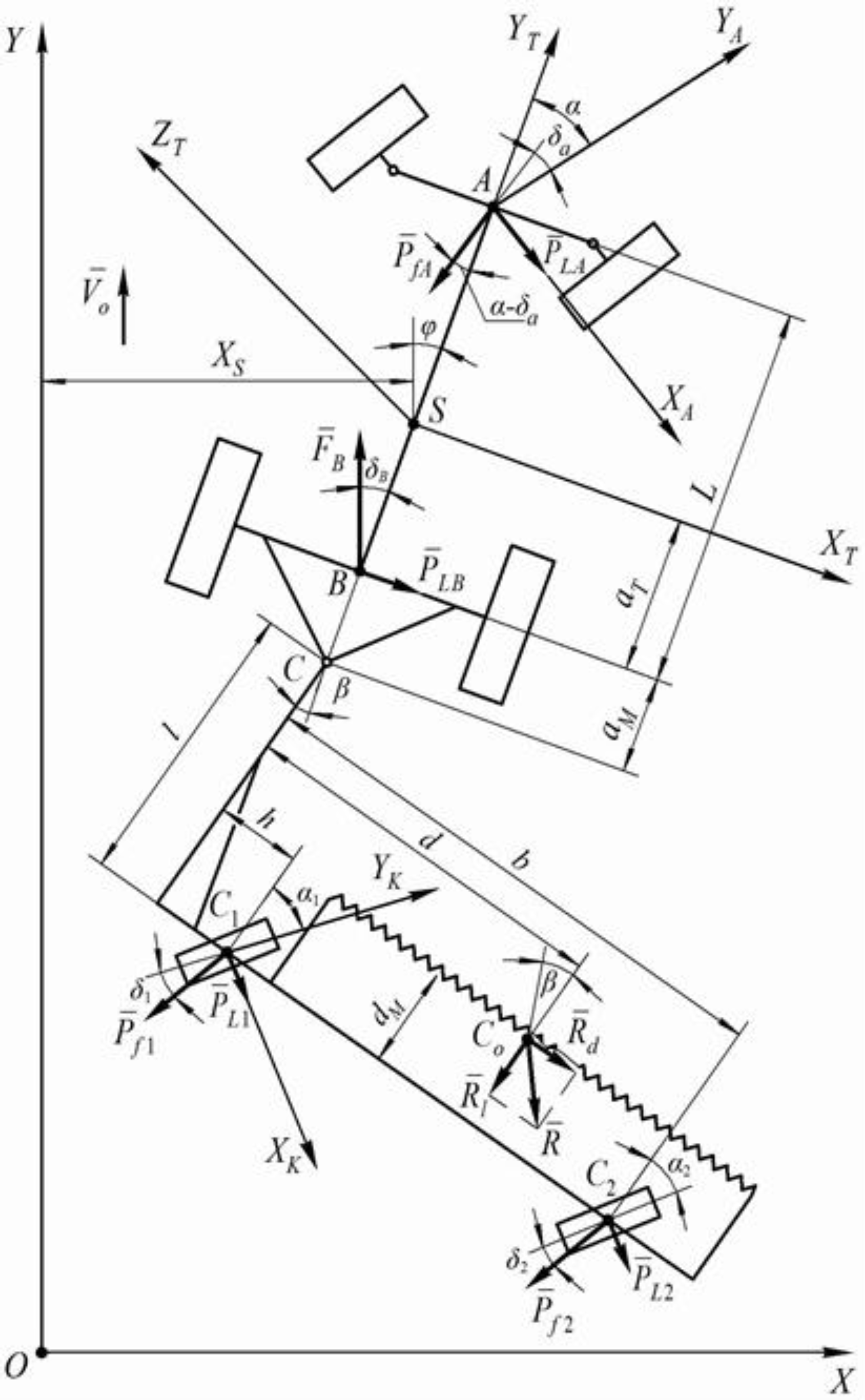
2.1. Mathematical Model of the Aggregating Wheeled Tractor

At first an equivalent scheme only of the aggregating wheeled tractor is constructed (Figure 3). The tractor is a four-wheel model in the form of a longitudinal frame with front-driven and rear driving wheels moving in a plane, parallel to the plane of the field surface, i.e., performing a plane-parallel movement. The aggregating wheeled tractor is depicted in the equivalent scheme in an arbitrary position (Figure 3). Its characteristic points are denoted by corresponding letters: S- center of mass point; A- middle of the axle of the driven wheel; B- the middle of the driving wheels; C- the hitch point of the aggregated machine. In this case, the pivots of the driven wheels, due to their small dimensions, enter the common length of the axles of the front wheels.
A system of coordinate axes is taken for this equivalent scheme. The surface of the field is strictly linked to the system of fixed Cartesian coordinates X O Y Z which denotes the plane of the field surface (axis Z is not shown). A separate spatial system of coordinate axes is drawn through the center of masses of the aggregating tractor (point S ), in which axis S Y T coincides with the longitudinal axis of the tractor, axis S X T is directed to the right from the course of the tractor but axis S Z T —vertically up. In addition, to indicate the direction of movement of the front-driven wheels of the tractor, a moving coordinate system X A A Y A with the origin at point A is chosen. Besides, axis A Y A always coincides with the direction of the movement of the front-driven wheels of the aggregating tractor (parallel to the plane of the indicated wheels) at an arbitrary moment of time, and axis A X A is directed perpendicular to axis A Y A and to the right from the course of the tractor. Taking into account the accepted assumptions and the advanced hypothesis, it is assumed that during its working run the aggregating wheeled tractor performs a movement relative to the fixed coordinate system X O Y , which will be a forward uniform movement with speed V 0 (Figure 3). While executing a working movement under the impact of random factors, the aggregating tractor deviates from its original position, receives additional speed and starts its relative movement in plane X O Y . In this case, plane Y T S X T connected with the center of masses of the aggregating tractor turns in X O Y around the vertical axis S Z T which passes through point S . The measure of this rotation will be angle φ , formed by the longitudinal axis of symmetry S Y T of the wheeled aggregating tractor and axis O Y .
During the relative movement of the tractor its center of masses moves along axis O X , which is characterized by a change in the coordinate X S (Figure 3). Thus, the aggregating tractor, with respect to plane X O Y , has two degrees of freedom, which correspond to coordinates: the linear coordinate X S and the angular coordinate φ . These coordinates are taken as generalized coordinates of the discussed dynamical system.
Furthermore, external forces acting upon the aggregating wheeled tractor are designated on the equivalent scheme. The forces that are acting in its plane-parallel movement (Figure 3) are the following:
(a)
the driving force F ¯ B of the rear wheels summing up from the two driving wheels of the tractor is applied at point B and forms a drift angle δ B with the longitudinal axis of symmetry of the tractor;
(b)
the rolling resistance force P ¯ f A of the front wheels of the tractor, which also sums up from the two wheels, is applied at the intersection point of their axis with the longitudinal axis S Y T (point A ) and deviated from the direction of the movement of its propellers by the drift angle δ A ;
(c)
lateral forces, respectively, from two wheels: P ¯ L A and P ¯ L B , applied at points A and B , respectively;
(d)
the traction resistance force P ¯ K R of the windrower movement, applied at point C and deviated from the longitudinal axis of the aggregating tractor, i.e., from axis S Y T , by angle β .
It should be noted here that the main moment of the forces acting upon the windrower (the turning moment M t relative to point C ) is not transmitted onto the tractor due to the pivotal connection of the aggregated asymmetric machine at point C . Consequently, the impact of the trailing asymmetric machine upon the aggregating tractor appears only as its traction resistance P ¯ K R and its turning (deviation) angle β in a horizontal plane.
The differential equations of a plane-parallel movement of the wheeled aggregating tractor are composed, using for this purpose the initial equations in the Lagrange form of the second kind [26,27]:
d d t ( T T q ˙ i ) T T q i = Q i
where T T —the kinetic energy of the aggregating tractor;
q i —generalized coordinates;
Q i —generalized forces by the respective generalized coordinates.
The kinetic energy T T of the aggregating tractor in relation to plane X O Y can be found from this equation:
T T = M T · V S 2 + J S · ω T 2 2
where M T —the mass of the aggregating tractor;
V S —the linear velocity of the center of masses of the tractor in plane X O Y ;
J S —the inertia moment of the tractor in relation to the vertical axis S Z T ;
ω T —the angular speed of turning of the tractor around axis S Z T .
If the linear V S and angular ω T velocities are expressed in terms of the generalized coordinates X S and φ , you obtain:
V S = X ˙ S
ω T = φ ˙
Then, taking this into account, the kinetic energy T T of the aggregating tractor is equal to:
T T = M T · X ˙ S 2 + J S · φ ˙ 2 2
Since the kinetic energy of the aggregating tractor, determined by Equation (3), depends only on velocities X ˙ S and φ ˙ and does not depend on the generalized coordinates themselves, then:
T T q i = 0
The partial derivatives with respect to velocities X ˙ S and φ ˙ of the respective generalized coordinates are:
T T X ˙ S = M T · X ˙ S
T T φ ˙ = J S · φ ˙
The time derivatives of each of the partial derivatives obtained above are determined by the corresponding equations:
d d t ( T T X ˙ S ) = M T · X ¨ S
d d t ( T T φ ˙ ) = J S · φ ¨
Using the obtained Equations (7) and (8), considering (4) with respect to two generalized coordinates X S and φ , based on (1), a system of differential equations of the plane-parallel movement of the aggregating wheeled tractor is obtained, which has the following form:
{ M T · X ¨ S = Q X S J S · φ ¨ = Q φ
Now the definition of generalized forces entering into the system of differential Equation (9) is proceeded. To determine the generalized force by the generalized coordinate X S , the equation of the elementary work of forces on possible displacement δ X S is used:
δ A X S = P L A · c o s ( φ + α ) · δ X S P f A · s i n ( φ + α δ A ) · δ X S + P L B · c o s φ · δ X S F B s i n ( δ B φ ) · δ X S P K R · s i n ( φ + β ) · δ X S
where α —the turning angle of the driven wheels of the aggregating tractor.
The generalized force by the generalized coordinate is calculated from Equation (10) and is equal to:
Q X S = δ A X S δ X S = P L A · c o s ( φ + α ) P f A · s i n ( φ + α δ A ) + P L B · c o s φ F B · s i n ( δ B φ ) P K R · s i n ( φ + β )
Thus, this generalized force Q X S is equal to the sum of the projections of all the active external forces onto axis O X , applied to the aggregating wheeled tractor. To determine the generalized force Q φ by the generalized coordinate φ , the equation for the elementary work of forces on possible displacement δ φ is used:
δ A φ = P L A · ( L a T ) · c o s α · δ φ P f A · ( L a T ) · s i n ( α δ A ) · δ φ P L B · a T · δ φ + F B · a T · s i n δ B · δ φ + P K R · ( a T + a M ) · s i n β · δ φ .
From Equation (12) you obtain:
Q φ = δ A φ δ φ = P L A · ( L a T ) · c o s α P f A · ( L a T ) · s i n ( α δ A ) P L B · a T + F B · a T · s i n δ B + P K R · ( a T + a M ) · s i n β
Csequently, the generalized force Q φ with respect to the angular generalized coordinate φ is equal to the algebraic sum of the moments of all the active external forces with respect to point S .
Analyzing the obtained Equations (11) and (13) for the generalized forces Q X S and, there is a possibility to simplify these equations since for the small angles the values of the cosines can be approximately considered equal to ones, and the values of the sines equal to the angles themselves. Taking into account that
F B F f A P K R = 0
Equation (11) can be presented as:
Q X S = P L A + P L B P f A α + P f A δ A F B δ B P K R β
Similar transformations are carried out also for Equation (13), additionally considering the small values of angles α and β .
Finally, an equation for the determination of the generalized force Q φ of this kind is obtained:
Q φ = P L A · ( L a T ) P f A · α · ( L a T ) P L B · a T + P f A · δ A · ( L a T ) + F B · δ B · a T + P K R · β · ( a T + a M )
The forces P L A and P L B entering Equations (15) and (16) can be replaced by equations formed based on the so-called hypothesis of “lateral drift” of tires of the pneumatic wheels [10] of the kind:
P L A = k A · δ A
P L B = k B · δ B
where k A , k B —the coefficients of the lateral drift of the pneumatic tires of the tractor.
In Equations (17) and (18) it is necessary to substitute the values of the drift angles δ A and δ B , which are determined on the basis of the construction of velocity plans of points A and B , i.e., the mid-points of the front (driven) and the rear (driving) axles of the aggregating tractor in their plane-parallel movement in a horizontal plane X O Y . The indicated velocity plans are constructed, which made it possible to graphically find the values of velocities V A and V B , then through their projections on axes X and Y , also the corresponding tangents, and, neglecting the small values, to find angles δ A and δ B themselves [22]. As a result, the final equations for lateral forces P L A and P L B of the hollowing kind were defined:
P L A = k A · [ X ˙ S ( L a T ) φ ˙ V 0 + φ + α ]
P L B = k B · [ X ˙ S a T · φ ˙ V 0 + φ ]

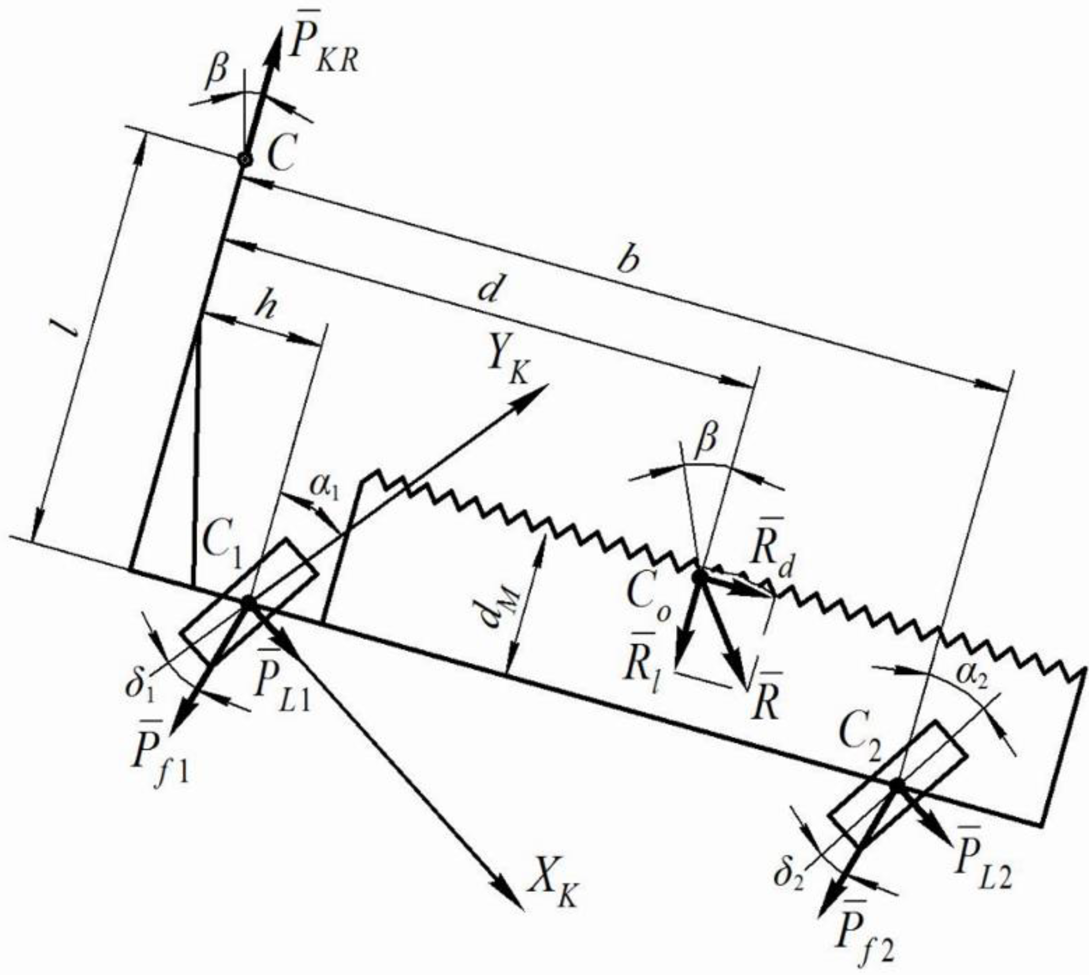
2.2. Mathematical Model of the Trailed Windrower

To construct a calculated mathematical model of the entire asymmetric machine-and-tractor aggregate, it is necessary further to consider the equivalent scheme of its technological part, i.e., the trailed windrower (Figure 4).
To indicate the position of the supporting wheels of the windrower at an arbitrary moment of time, a movable coordinate system Y K C 1 X K is shown in Figure 3, strictly linked with the left supporting wheel of the windrower. In the presented form, the trailed windrower, as a dynamic system, can be considered as a physical pendulum having only one degree of freedom—the turning angle β in a horizontal plane (Figure 4). It is this turning angle β that will be the generalized coordinate in the subsequent composition of differential equations as initial equations of dynamics in the Lagrange form of the second kind (1). The components, necessary for Equation (1) are then defined. Thus, the kinetic energy T H of the aggregated windrower is equal to:
T H = J C · β ˙ 2 2
where J C —the inertia moment of the windrower with respect to the vertical axis passing through point C ; β —the angular turning velocity of the windrower around point C .
The necessary partial derivatives entering the initial Lagrange equations of the second kind (1) are found from the following equations:
T H β ˙ = J C · β ˙
T H β = 0
d d t ( T H β ˙ ) = J C · β ¨
Taking into consideration Equations (23) and (24), the differential equation of the movement of the trailed windrower has the following form:
J C · β ¨ = Q β
To determine the generalized force Q B which enters into Equation (25), external forces acting upon the trailed windrower must be denoted. The external forces acting upon the windrower during its technological process are the following:
(a)
the longitudinal R ¯ l and the transverse R ¯ d components of the resistance forces of the harvested stubble mass that are applied to the windrower at point C 0 ;
(b)
the rolling resistance force P ¯ f 1 of the left-side wheel of the windrower applied at point C 1 and deviated from the plane of the wheel by the drift angle δ 1 ;
(c)
the rolling resistance force P ¯ f 2 of the two right-side wheels of the windrower (in the diagram they are represented as one equivalent wheel), which is applied at point C 2 and is deviated from the plane of the wheel by the drift angle δ 2 ;
(d)
lateral forces P ¯ L 1 and P ¯ L 2 , applied respectively to the left-side and the right-side wheel of the windrower at points C 1 and C 2 .
The equation for the elementary work of forces on possible displacement is used to determine the generalized force Q β by the generalized coordinate β :
δ A β = R l · d · δ β R d ( l d M ) · δ β + P f 1 c o s ( α 1 δ 1 ) · h · δ β + P f 2 ·   c o s ( α 2 δ 2 ) · b · δ β +   P f 1 s i n ( α 1 δ 1 ) · l · δ β + P f 2 s i n ( α 2 δ 2 ) · l · δ β P L 1 · c o s α 2 ·   l · δ β   P L 2 · c o s α 2 · l · δ β + P L 1 s i n α 1 · h · δ β + P L 2 s i n α 2 · b · δ β
where d, l, dM, h and b—the design parameters of the windrower (see Figure 4); α 1 and α 2 —the installation angles respectively of the left-side and the right-side wheels of the windrower.
From Equation (26) the generalized force Q β by the generalized angular coordinate β is:
Q β = δ A β δ β = R l · d R d ( l d M ) +   P f 1 c o s ( α 1 δ 1 ) · h + P f 2 · c o s ( α 2 δ 2 ) · b +   P f 2 s i n ( α 2 δ 2 ) · l P L 1 · c o s α 1 · l P L 2 · c o s α 2 · l +   P L 1 s i n α 1 · h +   P L 2 · s i n α 2 · b
Just as in the previous case, the values of the cosines of the small angles can be replaced by ones, and the sines by the angles themselves, and, in addition, if the small values of angles α 1 and α 2 are taken into account, then Equation (26) can be represented in this form:
Q β = R l · d · R d ( l d M ) + P f 1 · h + P f 2 · b + P f 1 · l · ( α 1 δ 1 ) + P f 2 · l · ( α 2 δ 2 ) P L 1 · l P L 2 · l +   P L 1 · α 1 · h +   P L 2 · α 2 · b
In addition, from Figure 4 it can be seen that
R d = R l · t g β
In addition, since the value of angle β is small, then t g β β , therefore:
R d = R l · β
As in the case with the aggregating wheeled tractor, the lateral forces P ¯ L 1 and P ¯ L 2 acting upon the supporting wheels of the windrower can be replaced by equations also formed based on the hypothesis about the “lateral drift” of the pneumatic tires of its wheels:
P L 1 = k 1 · δ 1
P L 2 = k 2 · δ 2
where K 1 , K 2 —the coefficients of the lateral drift of the pneumatic tires of the supporting wheels of the windrower; δ 1 , δ 2 —the drift angles of the pneumatic supporting wheels of the windrower.
As in the previous case, in order to determine the lateral forces P ¯ L 1 and P ¯ L 2 , it was necessary to find the drift angles δ 1 , δ 2 of the left-side and the right-side supporting wheels of the windrower, respectively, for which velocity plans have been also constructed to find the velocities of points C 1 and C 2 , and their projections on axes X and Y , and, considering the tangents of the angles and neglecting the small values, the final equations for these drift angles of this type were found:
δ 1 = X ˙ S + φ ˙ ( a T + a M ) + β ˙ ( l 2 + h 2 ) 1 2 ˙ V 0 + φ + β + α 1
δ 2 = X ˙ S + φ ˙ ( a T + a M ) + β ˙ ( l 2 + b 2 ) 1 2 ˙ V 0 + φ + β + α 2
By substituting Equations (33) and (34) into (31) and (32), the values of the lateral forces P ¯ L 1 and P ¯ L 2 are finally obtained and then used to find the generalized force Q β .
Taking into consideration Equations (30), (31), the generalized force Q β , determined by Equation (27), can be presented by the following form:
Q β = R l · d · R d ( l d M ) · β + P f 1 · h + P f 2 · b + P f 1 · l · ( α 1 δ 1 ) + P f 2 · l · ( α 2 δ 2 ) k 1 · δ 1 · l k 2 · δ 2 · l + k 1 · δ 1 · α 1 · h + k 2 · δ 2 · α 2 · b .
Since the product of two small values is even smaller, the sum of the last two terms ( k 1 · δ 1 · α 1 · h ) + ( k 2 · δ 2 · α 2 · b ) in Equation (35) can be neglected. In such a case:
Q β = R l [ d ( l d M ) · β ] + P f 1 [ h + ( α 1 δ 1 ) · l ] + P f 2 [ b + ( α 2 δ 2 ) · l ] k 1 · δ 1 · l k 2 · δ 2 · l
Taking into account Equations (33) and (34), as a result, this final equation for the generalized force Q β for the trailed windrower is obtained:
Q β = R l [ d ( l d M ) β ] + P f 1 { h + [ α 1 ( X ˙ S + φ ˙ ( a T + a M ) + β ˙ ( l 2 + h 2 ) 1 2 ˙ V 0 + φ + β + α 1 ) ] · l } + P f 2 { b + [ α 2 ( X ˙ S + φ ˙ ( a T + a M ) + β ˙ ( l 2 + b 2 ) 1 2 ˙ V 0 + φ + β + α 2 ) ] · l } k 1 · l ( X ˙ S + φ ˙ ( a T + a M ) + β ˙ ( l 2 + h 2 ) 1 2 ˙ V 0 + φ + β + α 1 ) k 2 · l ( X ˙ S + φ ˙ ( a T + a M ) + β ˙ ( l 2 + b 2 ) 1 2 ˙ V 0 + φ + β + α 2 )

3. Results and Discussion

3.1. Mathematical Model of the Entire Asymmetric Machine-and-Tractor Aggregate

By substituting Equations (15), (16) and (37) for generalized forces Q X S , Q φ and Q β into Equations (9) and (25), respectively, considering Equations (19) and (20), and discarding terms of a higher order of smallness, after a series of transformations the following system of the second-order linear differential equations, describing the movement of the asymmetric machine-and-tractor aggregate in a horizontal plane, is obtained:
{ A 11 · X ¨ S + A 12 · X ˙ S + A 13 · φ ˙ + A 14 · φ + A 15 · β = f 11 · α A 21 · φ ¨ + A 22 · φ ˙ + A 23 · φ + A 24 · X ˙ S + A 25 · β = f 21 · α A 31 · β ¨ + A 32 · β ˙ + A 33 · β + A 34 · φ ˙ + A 35 · φ + A 36 · X ˙ S = f 31
where:
  • A 11 = M T ;
  • A 12 = k A + k B + P f A F B V 0 ;
  • A 13 = ( k A + P f A ) · ( L a T ) + ( F B k B ) · a T V 0 ;
  • A 14 = F B k A k B P f A ;
  • A 15 = P K R ;
  • A 21 = J S ;
  • A 22 = ( k A + P f A ) · ( L a T ) 2 + ( k B F B ) · a T 2 V 0 ;
  • A 23 = A 13 · V 0 ;
  • A 24 = A 13 ;
  • A 25 = P K R · ( a T + a M ) ;
  • A 31 = J C ;
  • A 32 = l · [ ( k 1 + P f 1 ) · ( l 2 + h 2 ) 1 2 + ( k 2 + P f 2 ) · ( l 2 + b 2 ) 1 2 ] V 0 ;
  • A 33 = R l · ( l d M ) + l · ( k 1 + k 2 + P f 1 + P f 2 ) ;
  • A 34 = l · ( a T + a M ) · ( k 1 + k 2 + P f 1 + P f 2 ) V 0 ;
  • A 35 = l · ( k 1 + k 2 + P f 1 + P f 2 ) ;
  • A 36 = A 35 V 0 ;
    f 11 = k A ;
  • f 21 = ( L a T ) · k A ;
  • f 31 = R l · d + P f 1 · h + P f 2 · b α 1 · l · k 1 α 2 · l · k 2 ;
The following notations are adopted in the system of differential Equation (38): MT and JS—the mass of the aggregating tractor and its moment of inertia in relation to the center of masses, respectively; kA, kB—the drift resistance coefficients of the pneumatic tires of the wheels of the front and rear axles of the aggregating wheeled tractor, respectively; k1, k2—the drift resistance coefficients of the pneumatic tires of the left-side and two right-side wheels of the trailed windrower, respectively; α 1 , α 2 —the angles of setting (divergence) of the left-side and the right-side wheels of the windrower; L, aT, aM, l, h, b, d and dM—the design parameters shown on the equivalent schemes (Figure 3 and Figure 4).
The developed theory of a plane-parallel movement of the asymmetric machine-and-tractor aggregate may serve as a basis for investigating the stability of the movement of a rather wide class of asymmetric machine-and-tractor aggregates operating in various branches of production.
Consequently, the basic concepts of the theory of a plane-parallel movement of the asymmetric machine-and-tractor aggregate consisting of an aggregating wheeled tractor and an asymmetric windrower are described by a system of differential Equation (38). Besides, an important circumstance is that the windrower is linked to the aggregating wheeled tractor by means of a cylindrical joint.

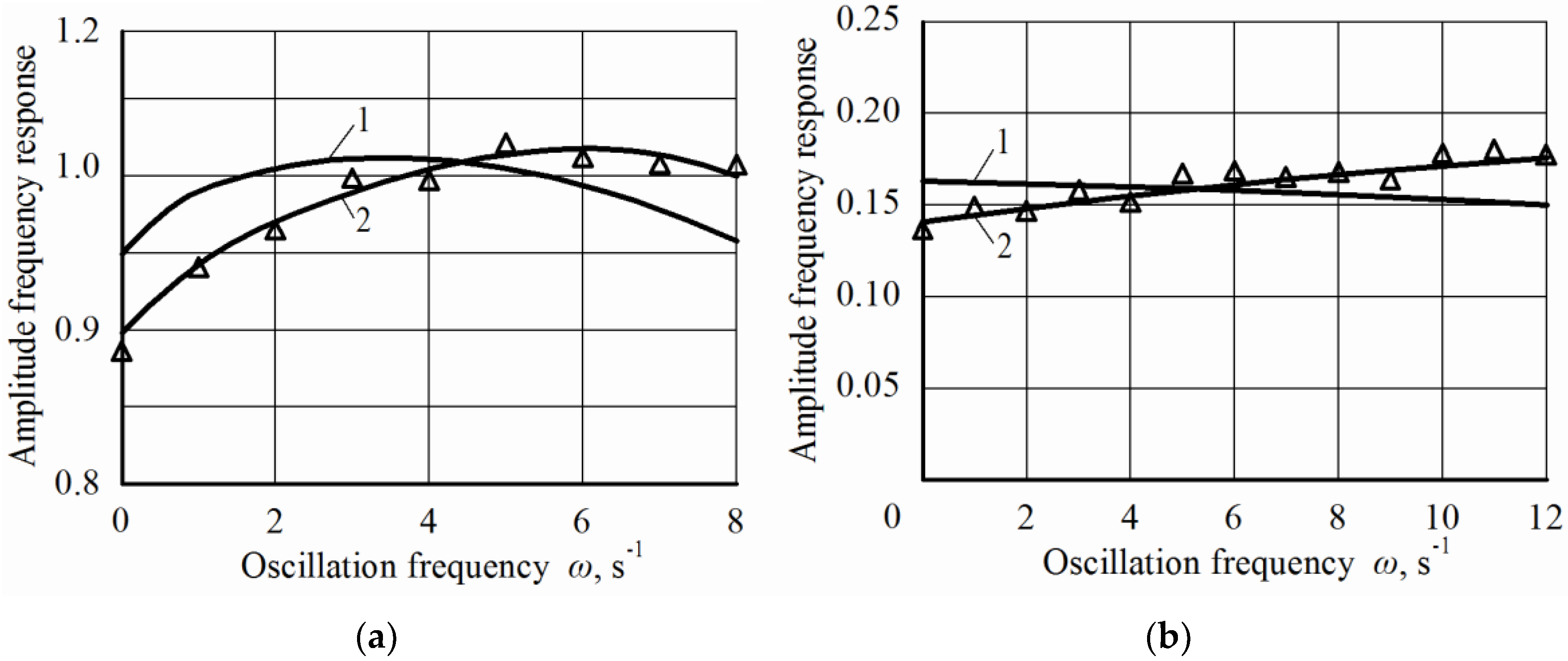
3.2. Experimental Verification of the Adequacy of the Mathematical Model

To verify the adequacy of the obtained mathematical model, experimental research of the amplitude-frequency response of the relative bearing φ of the tractor were carried out.
The experimental amplitude-frequency response was studied analyzing a harvesting asymmetric machine-and-tractor aggregate composed from a wheeled aggregating tractor MTZ-82 and a trailed swath header ZVP-6, which performs the technological process of collecting winter wheat into swaths (Figure 1).
The experimental studies were carried out with the following operative conditions: soil moisture 10–14% up to 15 cm of depth; soil hardness 2.3 MPa; density 496 wheat plants m−2, plant height 0.86 m.
During the experimental studies, the asymmetric swath header machine-and-tractor aggregate was moving at a speed of 2.45 m s−1. and the following parameters were registered: (a) the relative bearing of the aggregating tractor ( φ ); (b) the turning angle of the driven wheels of the aggregating tractor ( α ); (c) the turning angle of the swath header ( β ) in a horizontal plane. The obtained values φ , α , and β , were analyzed and statistical response were determined as the mean square deviations ( σ i ) and normalized spectral densities (Si).
The experimental amplitude-frequency response of the swath header machine-and-tractor aggregate were calculated from equation [9,10]:
A ( ω ) = σ y σ x · S y S x
where σ x , Sx—the mean square deviation and the normalized spectral density of the input value ( α or β );
σ y , Sy—the mean square deviation and the normalized spectral density of the output value ( φ );
ω —the frequency of variations of the control and the disturbing impact.
Figure 5 reports the comparison between the theoretical and experimental amplitude-frequency characteristics of the relative bearing φ of the tractor when reacting to the external impacts in the form of variations of the turning angle β of the swath header (a) and in the form of variations in the turning angle of the driven wheels α of the tractor (b).
Analysis of the obtained data show that the maximum discrepancy between the theoretical and experimental amplitude-frequency response does not exceed 8%.
Such a coincidence of experimental and calculated data points to the adequacy of the developed mathematical model, and then its use is appropriate for suitable design parameters of both the asymmetric swath header machine-and-tractor aggregate.
It is known [26,28] that when a dynamic system perceives one or another disturbance, the desired amplitude-frequency characteristic must be as small as possible. In an ideal case it must be equal to zero. At the same time, the phase-frequency shift (i.e., the delay in the reaction of the system) must be as large as possible. In case the dynamic system perceives a disturbance, the desired amplitude-frequency response should be equal to 0, the phase-frequency response, on the contrary, tend to ∞.

4. Conclusions

The developed system of linear differential equations of the second order makes it possible to describe mathematically the transverse displacement of the center of mass of an aggregating wheeled tractor, the rotation of its longitudinal axis of symmetry by some angle around this center of mass, and also the angle of deviation of the trailed swath header from the longitudinal axis of the tractor at an arbitrary moment of time.
When the asymmetric swath header machine-and-tractor aggregate, as a dynamic system, perceives a disturbing and a control impact, the maximum discrepancy between the theoretical and the experimental amplitude-frequency response does not exceed 8%, which points to the adequacy of the applied mathematical model for reliable substantiation of the scheme and the design parameters of the asymmetric swath header machine-and-tractor aggregate.

Author Contributions

The authors equally contributed to the present study.

Funding

This research received no external funding.

Acknowledgments

This research did not receive any specific grant from funding agencies in the public, commercial, or not-for-profit sectors.

Conflicts of Interest

The authors declare no conflict of interest.

References

  1. Pascuzzi, S. A multibody approach applied to the study of driver injuries due to a narrow-track wheeled tractor rollover. J. Agric. Eng. 2015, 46, 105–114. [Google Scholar] [CrossRef]
  2. Pascuzzi, S.; Santoro, F. Exposure of farm workers to electromagnetic radiation from cellular network radio base stations situated on rural agricultural land. Int. J. Occup. Saf. Ergon. 2015, 21, 351–358. [Google Scholar] [CrossRef] [PubMed]
  3. Cole, H.P.; Myers, M.L.; Westneat, S.C. Frequency and severity of injuries to operators during overturns of farm tractors. J. Agric. Saf. Health 2006, 12, 127–138. [Google Scholar] [CrossRef] [PubMed]
  4. Hunter, A.G.M.; Owen, G.M. Tractor overturning accidents on slopes. J. Occup. Accid. 1983, 5, 195–210. [Google Scholar] [CrossRef]
  5. Bevly, D.M.; Gerdes, J.C.; Parkinson, B.W. A new yaw dynamic model for improved high speed control of a farm tractor. J. Dyn. Syst. Meas. Control 2002, 124, 659–667. [Google Scholar] [CrossRef]
  6. Deng, W.K.; Kang, X. Parametric Study on Vehicle-Trailer Dynamics for Stability Control (No. 2003-01-1321); SAE Technical Paper; SAE International: Troy, MI, USA, 2003. [Google Scholar]
  7. Hac, A.; Fulk, D.; Chen, H. Stability and control considerations of vehicle-trailer combination. SAE Int. J. Passeng. Cars Mech. Syst. 2008, 1, 925–937. [Google Scholar] [CrossRef]
  8. Wu, D.H. A theoretical study of the yaw/roll motions of a multiple steering articulated vehicle. Proc. Inst. Mech. Eng. Part D J. Automob. Eng. 2001, 215, 1257–1265. [Google Scholar] [CrossRef]
  9. Bhatia, N.P.; Szegő, G.P. Stability Theory of Dynamical Systems; Springer: Heidelberg, Germany, 2002; ISBN 978-3-540-42748-3. [Google Scholar]
  10. Bulgakov, V.; Ivanovs, S.; Adamchuk, V. Estimated mathematical model of plane-parallel motion of trailed hemp harvesting aggregate. In Proceedings of the 14th International Scientific Conference: “Engineering for Rural Development”, Jelgava, Latvia, 20–22 May 2015; pp. 33–40. [Google Scholar]
  11. Bulgakov, V.; Ivanovs, S.; Adamchuk, V.; Nowak, J. Theoretical investigation of steering ability of movement of asymmetric swath header-and-tractor aggregate. In Proceedings of the 17th International Scientific Conference: “Engineering for Rural Development”, Jelgava, Latvia, 23–25 May 2018; pp. 301–308. [Google Scholar] [CrossRef]
  12. Bulgakov, V.; Ivanovs, S.; Adamchuk, V.; Nadykto, V. Theoretical investigation of turning ability of machine and tractor aggregate on basis of ploughing and intertilling wheeled tractor. In Proceedings of the 15th International Scientific Conference: “Engineering for Rural Development”, Jelgava, Latvia, 25–27 May 2016; pp. 1077–1084. [Google Scholar]
  13. Kang, X.; Deng, W. Vehicle-Trailer Handling Dynamics and Stability Control—An Engineering Review (No. 2007-01-0822); SAE Technical Paper; SAE International: Troy, MI, USA, 2007. [Google Scholar]
  14. Kyurchev, V.M. Mechanical and Technological Foundations of Aggregating Ploughing and Intertilling Tractors; Monograph, Institute for Agricultural Engineering and Electrification Press: Glevaha, Ukraine, 2015. [Google Scholar]
  15. Merkin, D. Introduction to the Stability Theory of Movement; Science: Moscow, Russia, 1976. [Google Scholar]
  16. Dreizler, R.M.; Ludde, C.S. Theoretical Mechanics; Springer: Berlin, Germany, 2010. [Google Scholar]
  17. Rangavajhula, K.; Tsao, H.J. Effect of multi-axle steering on off-tracking and dynamic lateral response of articulated tractor-trailer combinations. Int. J. Heavy Veh. Syst. 2007, 14, 376–401. [Google Scholar] [CrossRef]
  18. Smith, M.J.; Wisten, M.B. A continuous day-to-day traffic assignment model and the existence of a continuous dynamic user equilibrium. Ann. Oper. Res. 1995, 60, 59–79. [Google Scholar] [CrossRef]
  19. Vasilenko, P. Introduction to Agricultural Mechanics; Agricultural Education: Kiev, Ukraine, 1996. [Google Scholar]
  20. Bulgakov, V.; Zaryshnyak, A.; Beloev, H.; Ivanovs, S. Investigation of amplitude-frequency response of disturbing and control impacts of asymmetric swath header machine-and-tractor aggregate. In Proceedings of the 17th International Scientific Conference: “Engineering for Rural Development”, Jelgava, Latvia, 23–25 May 2018; pp. 221–226. [Google Scholar] [CrossRef]
  21. Bulgakov, V.; Pascuzzi, S.; Ivanovs, S.; Kaletnik, G.; Yanovich, V. Angular oscillation model to predict the performance of a vibratory ball mill for the fine grinding of grain. Biosyst. Eng. 2018, 171, 155–164. [Google Scholar] [CrossRef]
  22. Bulgakov, V.; Grinik, I.; Lezhekin, A. Dynamics of the Grain Harvesting Aggregates; Agrarian Science: Kiev, Ukraine, 2010. [Google Scholar]
  23. Gyachev, L. Stability of the Movement of Agricultural Machines and Aggregates; Mechanical Engineering: Moscow, Russia, 1981. [Google Scholar]
  24. Nadykto, V. Analysis of the Turning Ability of the Machine and Tractor Aggregates on the Basis of Modular Means of Energy. Sci. Bull. Tavria Univ. Agric. Melitop. 2005, 29, 28–34. [Google Scholar]
  25. Gusjkov, V. Tractors: Theory; Mechanical Engineering: Moskow, Russia, 1988. [Google Scholar]
  26. Wiggins, S. Introduction to Applied Nonlinear Dynamical Systems and Chaos, 2nd ed.; Springer: New York, NY, USA, 2003; ISBN 0-387-00177-8. [Google Scholar]
  27. Piskunov, N. Differential and Integral Calculation; Mechanical Engineering: Moskow, Russia, 1970; Volume 2. [Google Scholar]
  28. Pascuzzi, S.; Anifantis, A.S.; Blanco, I.; Scarascia Mugnozza, G. Electrolyzer performance analysis of an integrated hydrogen power system for greenhouse heating a case study. Sustainability 2016, 8, 629. [Google Scholar] [CrossRef]
Figure 1. The aggregating wheeled tractor and the trailed asymmetric.
Agriculture 08 00151 g001
Figure 2. An equivalent scheme of the asymmetric machine-and-tractor aggregate.
Agriculture 08 00151 g002
Figure 3. An equivalent scheme of the aggregating tractor in its plane-parallel movement.
Agriculture 08 00151 g003
Figure 4. An equivalent diagram of an aggregated windrower.
Agriculture 08 00151 g004
Figure 5. Theoretical (1) and experimental (2) amplitude-frequency response of the relative bearing φ of the tractor when reacting to the external impacts in the form of variations of the turning angle β of the swath header (a) and in the form of variations in the turning angle of the driven wheels α of the tractor (b).
Agriculture 08 00151 g005

