Abstract
Conventional oat seeders suffer from poor seeding uniformity, a large coefficient of variation in seed volume, and significant seed wastage. To address these issues, a variable-capacity spoon-type oat precision hill seeder was designed based on the agronomic requirements of oat hole seeding and the structural characteristics of hill seeders. Through force analysis and theoretical calculations, the angular velocity range of the variable-capacity spoon-type oat precision hill seeder was determined to be within 0–6.9 rad/s. An experiment was conducted using the angular velocity of the hill seeder, the inclination angle of the seed guide spoon, and the length of the bridging groove as test factors. The ranges of these factors for optimal seed displacement performance were established. Based on the Box–Behnken test principle, a response surface test was designed using Design-Expert software (Design-Expert 13). Experimental results identified the optimal operating parameters as follows: an angular velocity of 4.9 rad/s for the hill seeder, a guide spoon inclination angle of 71.0°, and a bridging groove length of 10.9 mm. Under these conditions, the qualified rate, leakage rate, and multiple rates were 92.2%, 5.3%, and 2.6%, respectively. The results of the field trial showed that the seeding qualified rate was 91.2%, the leakage rate was 4.6%, and the multiple rate was 4.2%. The errors between the field test results and the simulation test results were −1.0%, −0.7%, and 1.6%, respectively, meeting the requirements for oat seeding.
1. Introduction
Oat is an annual herbaceous plant of Gramineae, which has the characteristics of cold resistance, drought resistance, barren resistance, and moderate salinity tolerance. Oats do not compete with major cereal crops such as corn and wheat for arable land, and they present a low agricultural risk coefficient [1]. As a result, oats have become an important specialty crop in ecologically fragile regions of China [2]. However, oat seeds have hulls and exhibit low flowability, which is the primary factor limiting the mechanized sowing of oats. This issue remains one of the key technical challenges that must be addressed to enable large-scale oat production [3].
Ensuring the uniform and stable operation of the seed metering device is critical for achieving the mechanized sowing of oats [4,5]. Currently, drill sowing remains the predominant method for oat cultivation. Internationally, oat drills primarily employ pneumatic centralized seeding systems, which adjust the sowing rate by regulating airflow velocity. Representative models such as the S-drill series pneumatic seeders from the United Kingdom, the Cirrus 4003-2 large-scale no-tillage combined seeder from Amazone in Germany, and the TERRASEM seeder from Austria offer high seeding accuracy and strong operational adaptability [6]; however, their high cost limits their suitability for oat cultivation in ecologically fragile areas of China. In contrast, the outer groove wheel seed metering device is the mainstream technology used in oat drills in China, owing to its simple structure and ease of adjustment [7,8]. A representative model is the 2BXF-6 multifunctional grain seeder. Compared with manual sowing, the use of oat drills has significantly improved seeding efficiency. Nevertheless, current oat drills still exhibit poor seeding uniformity, a high coefficient of variation in seeding rate, and considerable seed wastage. These shortcomings prevent them from meeting the requirements for precision sowing.
Mechanized dibbling was one of the primary methods for addressing the aforementioned issues. This approach not only significantly reduced seed wastage but also improved crop emergence and survival rates [9]. Zhang Qingsong et al. [10] designed a rectangular spoon-type precision hill seeder with a notched structure for rapeseed. This hill seeder effectively addressed the problems of seed wastage and uneven plant spacing associated with traditional rapeseed drilling. Similarly, the flower-trough duckbill-type buckwheat dibbler developed by Chen Yu et al. [11] enhanced the sowing accuracy and quality of buckwheat in mountainous areas. Zhang Guozhong et al. [12] proposed a double-chamber side-filling precision hill seeder for rice, featuring a curved brush seed-cleaning and seed-guarding structure, which achieved precision hill seeding of rice in large fields. Shi Linrong et al. [13] designed a precision hill seeder for Huperzia by modifying seed scooping spoons with tongues on both sides of the cavity to guide seeds into the spoon cavity more effectively. This design addressed the problem of a large coefficient of variation in seeding volume caused by serious filling leakage in traditional hill seeders. Li Hui et al. [14] developed a tongue-type precision hill seeder for hemp (Hu Ma) and, through simulation tests, found that increasing seed mobility could ensure complete filling of the scooping spoon, thereby improving sowing accuracy. These studies significantly enhanced the seeding quality of hill seeders and addressed the problems of high seed consumption associated with traditional strip planters, providing valuable references for the development of precision hill seeders for oats. However, research specifically focused on oat precision hill seeders remained limited, and specialized equipment for the mechanized hill seeding of oats was still lacking.
In the design and study of seed metering devices, it was challenging to obtain accurate parameters such as force, velocity, and displacement through physical testing alone [15,16,17]. However, these parameters were critical for the design and optimization of seed dischargers. Numerical simulation using the discrete element method (DEM) offered an effective solution to these challenges [18,19,20]. Consequently, researchers increasingly adopted DEM to simulate the working processes of seed dischargers. By simulating and analyzing the kinematic characteristics of seed dischargers, key structural parameters could be determined [21,22,23,24]. Furthermore, DEM was widely applied to the study of interaction mechanisms among seeds, agricultural machinery, and soil [25,26,27,28,29]. Based on these considerations, this study employed the discrete element method to conduct simulation tests.
In summary, this study focused on Mengyan 1 oat seeds cultivated in Inner Mongolia as the research subject. A variable-capacity spoon-type oat precision hill seeder was designed based on the agronomic requirements of oat hole seeding and the structural characteristics of hill seeders. The working process and key structural parameters of the hill seeder were simulated and analyzed using the discrete element method. The structural parameters were further optimized through response surface methodology, and the performance of the hill seeder was validated through field tests.
2. Materials and Methods
2.1. Structure and Working Principle of Hole Seeder
2.1.1. Hill Seeder Structure
The oat precision hill seeder primarily consists of a seed metering spoon, seed discharging nozzle, return spring, seed guard plate, shell, seed delivery tube, and other components, as shown in Figure 1. The seed metering spoon consists of an upper and lower part. The horizontal spacing between the upper and lower spoons can be adjusted, thereby enabling the volume of the seed.
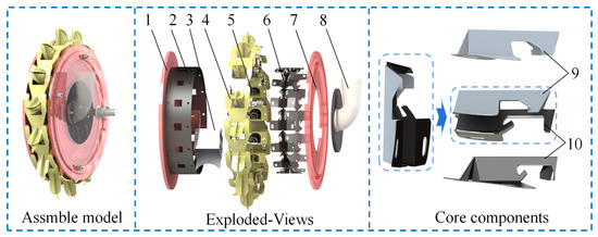
Figure 1.
Oat hill seeder structure diagram: 1. Backshell; 2. Seed dispenser roller; 3. Seed pad; 4. Seed dispenser; 5. Reset spring; 6. Seed metering spoon; 7. Frontshell; 8. Seed intake tube; 9. Upper seed metering spoon; 10. Lower seed metering spoon.
2.1.2. Principle of Operation of the Hill Seeder
Figure 2 shows the working principle diagram of the oat precision hill seeder. During operation, the hill seeder is passively driven to rotate through contact with the ground. In the seed filling area, the seed metering spoon scoops a quantity of seeds from the seed population into the seed guide spoon and rotates together with the hill seeder. When the seed metering spoon lifts out of the seed population, some oat seeds are supported by a force smaller than their weight. Due to the lack of support, these seeds subsequently fall into the cavity of the hill seeder, a process referred to as seed scoop clearing. During bridging clearing, oat seeds slide into the seed chamber along the bridging slots, with the length and depth of the slots determining the amount of seed that passes through. When a greater quantity of seeds is present, those insufficiently supported also fall into the cavity of the hill seeder. The oat seeds within the cavity of the seed metering spoon are then conveyed through the inlet hole of the seed discharge roller into the seed discharge nozzle in the seed guide area. When the seed discharge nozzle enters the soil, the pressure plate at the rear end of the nozzle contacts the ground. This action causes the nozzle to open, allowing the oat seeds to be smoothly discharged into the seed hole. At this point, the seeding operation is completed.
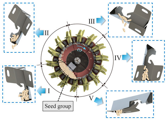
Figure 2.
Working principle diagram of oat hill seeder: I. seed filling area; II. seeding spoon clearing area; III. bridge clearing area; IV. seed guiding area; V. seeding area.
2.2. Key Component Design
2.2.1. Structural Design of Hill Seeder
The sowing conditions were determined based on the agronomic requirements for oat cultivation in cold and arid regions of northern China. Oats were sown at a rate of 150–225 kg/hm2 at a depth of 30 mm, with a row spacing of 100 mm (narrow rows) or 250 mm (wide rows), and a hole spacing of 100 mm.
Calculations showed that sowing 10–14 seeds per hole could meet the required sowing rate for oats. Considering that the diameter of the seed-taking drum ranges from 360 to 480 mm, the preliminary number of seed discharge nozzles was calculated as follows:
where Z is the number of seed discharge nozzles; D1 is the diameter of the hill seeder, mm; d is the sowing depth, mm; L is the plant spacing, mm.
By calculation, Z was determined to be approximately 13.19–16.96. To ensure the smooth operation of the oat hill seeder, the number of seed discharge nozzles was set to 14, resulting in 14 seed scoops. The diameter of the hill seeder is a key factor in designing the seeder size, as it is related to the number of seed discharge nozzles and the planting spacing, and can be calculated using the following formula:
where δ is the slip factor, which is taken as 9.3% for sandy soils.
According to Equation (2), the oat hill seeder diameter D1 was calculated to be 404.19 mm. Based on this result, the oat hill seeder diameter D1 was finalized as 410 mm in this study. The formula for calculating the number of rows of seed nozzles is:
where H is the height of the seed discharge nozzle, mm.
As shown in Figure 3, according to Equation (3), the height of the seed discharge nozzle H was calculated to be 60 mm. The diameter of the hill seeder D1 was 410 mm, and the inner diameter of the burrow planter D2 was 350 mm.
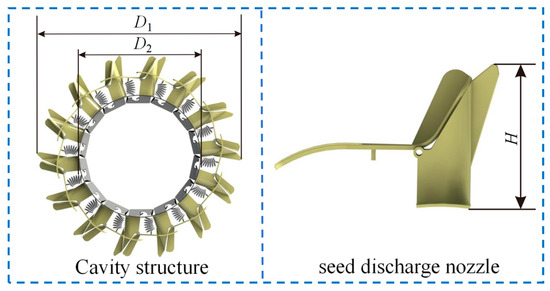
Figure 3.
Seeding mouth distribution map.
2.2.2. Structural Design of Seed Metering Spoon
The structure of the seed metering spoon mainly comprises a rear baffle, a fixed bottom plate, a seed guard tongue, a bridging groove, a seed guide tongue, and a seed guide spoon. Uniform distribution of the seed metering spoons along the inner surface of the drum is crucial for the performance of the hill seeder. To facilitate the rapid entry of seeds into the seed guide spoon, two seed guide tongues are positioned on either side of it. Uneven terrain can cause the hill seeder to tilt, resulting in seeds sliding out of the bridging groove. To prevent this, a seed guard tongue is installed at the end of the bridging groove, as shown in Figure 4.
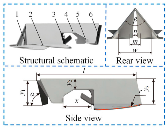
Figure 4.
Structure diagram of seed metering spoon: 1. rear baffle; 2. fixed bottom plate; 3. seed guard tongue; 4. bridging groove; 5. seed guide tongue; 6. seed guide spoon.
The structure of the seed guide spoon and bridging groove directly affects the effect of seed metering spoon taking and clearing seeds, which is designed as follows:
(1) Design of seed guide spoon:
Simulation revealed that the seed picking and seed clearing processes directly affect the seed displacement of the hill seeder, with the structure of the seed metering spoon being the key influencing factor. The seed metering spoon cavity is similar to a four-pronged cone, and its volume is mainly determined by the width of the spoon (w), the height of the spoon (y1), and the inclination angle of the seed guide spoon (α). Preliminary experiments revealed that the volume of the scoop cavity of a seed metering spoon should be approximately half the volume of an oat seed to meet sowing requirements. The volume of 10 to 14 oat seeds was measured to be approximately 102–142 mm3. To ensure that the seeding volume of the hill seeder meets agronomic requirements, it was determined that the volume of the seed metering spoon cavity should be 51–71 mm3, with the width of the spoon (w) being 10 mm and the height of the spoon (y1) being 8 mm. To ensure smooth seed flow from the filling zone into the seed metering scoop, the inclination angle of the seed guide spoon should be greater than the natural angle of repose of the oat seeds (31.4°).
(2) Design of bridging groove:
For the oat seed to slide along the bridging groove into the seed metering spoon cavity, the bridging groove cross-section angle β should be 0° to 134°. If β is too large, the bridging groove wall becomes less supportive of the seed, which is not favorable for the bridge to clear the seed. If β is too small, then the oat seed tends to congest the crossing bridging groove. The combined consideration β is taken as 65°. The calculation formula of the cross-section height of the bridging groove is:
where kb is the length adjustment factor, take 2.0~2.2; ymean is the average thickness of oat seeds, 2.2 mm.
The cross-section height y2 of the bridging groove is calculated to be 4.2–4.84 mm. In this study, y2 = 4.5 mm was determined. The length of the bridging groove determines the bridging seed clearing time and thus the amount of seed to be cleared. To meet the demand for seeding volume in different soil moisture conditions, the seed metering spoon is set as an upper and lower compound structure, so that the length of the bridging groove x is adjustable in the range of 5~20 mm.
(3) Design of other structural parameters:
To install the seed metering spoon in the drum without deformation, the bottom plate of the seed metering spoon was designed with a circular arc shape. The arc was designed with a radius of r = 175 mm, matching the inner diameter of the hill seeder. The height y3 = 10 mm was determined in this study based on the traditional seed metering spoon. The length of both the upper and lower seed metering spoons was 50 mm, and the total length of the compound structure was l = 50–65 mm. To prevent soil brought in by the hill seeder during operation from clogging the seed metering spoon cavity and altering its volume, exclusion gaps (n = 1.2 mm, m = 1.6 mm) were set at the rear baffle of the seed metering spoon and the guide spoon, respectively.
2.3. Theoretical Analysis
2.3.1. Force Analysis of Seed Filling Process
During the seed filling process, a three-dimensional Cartesian coordinate system was established with the center of mass of the oat seed as the origin. The x-axis is defined as perpendicular to the direction of the support force, the y-axis is aligned with the support force, and the z-axis is parallel to the inner wall of the hill seeder while remaining perpendicular to the x-axis. The oat seeds are subjected to gravity, support force, friction, and centrifugal force within the seed guide spoon. Assuming that the oat seeds within the seed guide spoon are in force equilibrium and at relative rest, the force analysis is shown in Figure 5.
where ω is the hill seeder angular velocity, rad/s; G1 is the gravitational force on the oat seed in the seed guide spoon, N; m1 is the mass of oat seed in the seed guide scoop, kg; μ is the static friction factor between the oat seed and the seed guide spoon; θ1 is the angle between the y-axis and the vertical direction, °; R is the radius of the inner wall of the hill seeder, mm; f1, f1′, f1″ are the friction forces on the oat seeds, N; F1 is the centrifugal force on the oat seed, N; N1 is the support force on the oat seed, N.
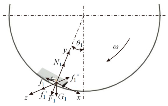
Figure 5.
Force analysis of the seed filling process.
To ensure that the oat seed slides smoothly into the seed guide spoon and rotates with it, it needs to be satisfied:
This can be obtained by bringing Equation (6) into Equation (5):
From Equation (7), the hill seeder angular velocity ω increases with the increase of θ1. θ1 = 90° when the seed metering spoon is in the picking limit position. To ensure smooth seed pickup by the seed metering spoon, the hill seeder angular velocity should be less than 11.6 rad/s.
2.3.2. Force Analysis of the Seed Metering Scoop Cleaning Process
Similarly, a spatial Cartesian coordinate system was established during the seed scoop clearing process. The x-axis is defined as perpendicular to the direction of the support force, the y-axis is oriented opposite to the support force, and the z-axis is parallel to the inner wall of the hill seeder while remaining perpendicular to the x-axis. Assuming that the oat seeds within the seed metering spoon are in force equilibrium and at relative rest, the force analysis is shown in Figure 6.
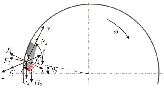
Figure 6.
Force analysis of seed metering spoon cleaning. G2′ is the gravity of the dropped seeds.
From the force analysis:
where G2 is the gravitational force on oat seeds during the seed metering scoop clearing stage, N; m2 is the quality of oat seed at the seed metering scoop clearing stage, kg; θ2 is the angle between the y-axis and the horizontal, °; f2, f2′, f2″ are the friction forces on the oat seeds, N; F2 is the centrifugal force on the oat seed, N; N2 is the support force on the oat seed, N.
When the combined force of friction and support force on the oat seed is less than the force of gravity, the oat seed utilizes its own gravity to complete the seed metering scoop clearing process. The force relationships are as follows:
where G2′ is the force of gravity on the removed oat seed, N; m2′ is the quality of cleared oat seed, kg.
2.3.3. Force Analysis of the Seed Cleaning Process Across the Bridge
Similarly, a spatial Cartesian coordinate system was established during the bridging clearing process. The x-axis is defined as perpendicular to the direction of the support force, the y-axis is oriented opposite to the support force, and the z-axis is parallel to the inner wall of the hill seeder while remaining perpendicular to the x-axis. Assuming that the oat seeds within the seed metering spoon are in force equilibrium and at relative rest, the corresponding force analysis is shown in Figure 7.
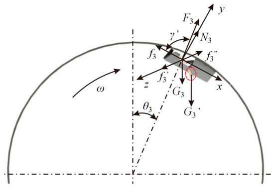
Figure 7.
Force analysis of the cleaning of the crossing bridge. G3′ is the gravity of the dropped seeds.
The combined force of the oat seed in the x direction and y direction is satisfied during the clearing stage across the bridge:
Among them:
where G3 is the gravitational force on the oat seed in the bridging groove, N; m3 i1 is the mass of oat seed in the bridging groove, kg; θ3 is the angle between the y-axis and the horizontal, °; f3, f3′, f3″ are the friction forces on the oat seeds, N; F3 is the centrifugal force on the oat seed, N; N3 is the support force on the oat seed, N.
When the hill seeder is rotated, the centrifugal force F3 on the seed as it passes through the bridging groove is much greater than N3. Therefore, the support force on the seed for this process is negligible. From Equations (10) and (11), we can get:
From Equation (12), it can be seen that the hill seeder radius R, the seed metering spoon rotation angle θ3, and the seed guide spoon inclination angle γ directly affect the hill seeder critical speed. A higher number of seeds entering the seed guide zone will increase the multiple seeding rate. Therefore, the bridge clearing phase needs to be completed during the transition from the horizontal to the vertical position of the seed metering spoon, with a θ3 limit value of 90° and an angular velocity of the hill seeder greater than zero. This gives a range of angular velocity of the hill seeder of 0 < ω < 6.9 rad/s.
2.4. Simulation Test
2.4.1. Simulation Modeling
Meng Yan No. 1 seeds were selected for the experiment. The simulation assumed that all seeds had the same external dimensions due to their small size and minimal variability between individual seeds. The oat seed was modeled in 3D using SolidWorks software (SolidWorks 2018), and the resulting model was converted into .step format. As shown in Figure 8 [30], the oat model in .step format was imported into EDEM simulation software (EDEM simulation 2022) for the seed filling simulation.
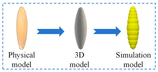
Figure 8.
Quinoa seed simulation model.
To reduce the simulation time, the 3D model of the hill seeder was simplified by retaining the back shell, the seed dispenser roller, and the seed metering spoon. As shown in Figure 9, the simplified 3D model was imported into the EDEM simulation software using the method described above.
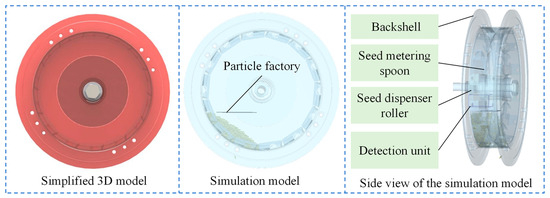
Figure 9.
Simulation model of a hill seeder.
2.4.2. One-Factor Simulation Test
According to the literature [31,32], each parameter of this simulation is determined as shown in Table 1. The pellet plant set the oat simulation model size to a normal distribution, and the pellet plant was distributed above the seed filling area of the hill seeder to generate a total of 20,000 pellets. The total duration of the simulation was 5 s, and the data were recorded once every 0.01 s. Seed detection units are added to the seed filling and clearing areas for detecting the number of seeds filled and cleared, respectively.

Table 1.
Simulation parameters.
The angular velocity of the hill seeder was calculated to be 0 < ω < 6.9 rad/s by force analysis, so the range of angular velocity of the hill seeder was selected to be 0.5–6.5 rad/s for the simulation test. The pre-test revealed that the inclination angle of the seed guide spoon directly affects the seed filling performance of the hill seeder. Therefore, an inclination angle range of 40–80° was selected for the seed guide spoon. The length of the bridging groove, which directly affects the seed clearing performance, was selected to range from 5 to 25 mm, as shown in Table 2.
Table 2.
Table of one-factor tests.
2.4.3. Response Surface Test
To further investigate the potential interactions among the three factors and their effects on the seed discharge performance of the hill seeder, based on the Box–Behnken test principle, a three-level, three-factor response surface methodology (RSM) experiment was conducted. The angular velocity of the hill seeder, the inclination angle of the seed guide spoon, and the length of the bridging groove were chosen as factors, while the qualified rate, leakage rate, and multiple rate were used as evaluation indices. The corresponding factor codes are listed in Table 3.
Table 3.
Test factors and coding.
2.5. Field Validation Tests
The test was conducted on 20 April 2024 in the experimental field of Humble Dragon Landscape Science and Technology Co. Data collection was carried out in the stabilized working area of the planter. A total of six test sets were conducted, each containing 250 data points. Seeding was considered satisfactory when the number of oat seeds per hole was between 10 and 14. A missed seeding was defined as fewer than 10 oat seeds per hole, while reseeding was defined as more than 14 oat seeds per hole.
3. Results
3.1. Hill Seeder Movement Process
The oat seed batch exhibited some mobility when the hill seeder was rotated. Seeds at the bottom of the batch moved upward due to friction. When the gravitational force on the seeds exceeded the frictional force, the seeds slid downward along the top of the batch. As illustrated in Figure 10, the entire seed group exhibited upward movement at the bottom, remained stationary in the middle, and showed a return flow at the top.
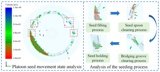
Figure 10.
Simulation test results.
3.1.1. Angular Velocity of the Hill Seeder on the Dynamic Performance of Seed Batch
The dynamic performance curves of the seed batch at different angular velocities of the hill seeder are shown in Figure 11a. The mean velocities of the seed batch at angular velocities of the hill seeder were 0.22, 0.26, 0.32, 0.38, and 0.45 m/s. The velocity of the seed batch increased with the angular velocity of the hill seeder. Appropriately increasing the angular velocity of the hill seeder enhanced the mobility of the seed batch, thereby improving seed filling performance. Therefore, it can be concluded that the angular velocity of the hill seeder regulates the mobility of the seed batch and influences seed filling performance.
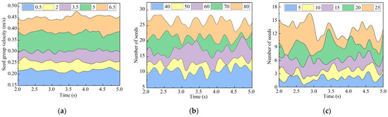
Figure 11.
Simulation test results: (a) the dynamic performance curves of the seed batch for different angular velocities of the hill seeders; (b) seed filling performance curves at different inclination angles of the seed guide spoons; (c) seed clearing performance curves for different lengths of the bridging grooves.
3.1.2. Influence of Inclination Angle of the Seed Guide Spoon on Seed Filling Performance
The number of seeds filled in the filling zone at different inclination angles of the seed guide spoon is shown in Figure 11b. The number of seeds filled is measured by means of a detection unit. The mean number of seeds filled at different inclination angles of the seed guide spoon were 10.5, 13.0, 17.5, 21.0, and 26.0, respectively. The number of seeds filled increases as the inclination angle of the seed guide spoon increases. Simulation tests revealed that when the number of seeds filled exceeds 14, the final number of seeds discharged can meet the required specifications after the seed clearing area is cleared. However, when the inclination angle of the seed guide spoon is less than 50°, the number of seeds filled is insufficient and fails to meet the requirements. It can be seen that the inclination angle of the seed guide spoon regulates the amount of seed filling and influences the filling performance.
3.1.3. Influence of Length of the Bridging Groove on Seed Clearing Performance
Figure 11c shows the number of seeds cleared in the bridging clearing area for different lengths of the bridging groove. Measurement of the number of seeds was cleared by means of a detection unit. The mean numbers of cleared seeds at different bridging groove lengths were 2.0, 4.0, 6.0, 9.0, and 13.0. The number of cleared seeds increased with the length of the bridging groove. The length of the bridging groove affected both the bridging clearing time and the seed clearing area. Increasing the length of the bridging groove enlarged the seed clearing area and prolonged the clearing time, resulting in a greater number of seeds requiring clearance. Therefore, it can be concluded that the length of the bridging groove regulates the seed clearing amount and significantly affects seed clearing performance.
3.2. Results of the One-Factor Test
3.2.1. Results of a One-Factor Test on the Angular Velocity of the Hill Seeder
The seed discharge performance curves for different angular velocities of the hill seeder are shown in Figure 12a. The qualification rate first increased and then decreased as the angular velocity of the hill seeder increased. The multiple rate exhibited an increase–decrease–increase pattern with increasing angular velocity of the hill seeder. The leakage rate first decreased and then gradually increased as the angular velocity of the hill seeder increased. At lower angular velocities of the hill seeder, the average velocity of the seed batch was lower and less mobile, which hindered seed filling and resulted in a higher leakage rate. At higher angular velocities, the centrifugal force on the seed became more unfavorable for seed clearance, leading to a higher multiple rate. Seed filling performance could be improved by appropriately increasing the angular velocity of the hill seeder. Therefore, the optimal range of angular velocity for the hill seeder was determined to be 3.5–5.5 rad/s.
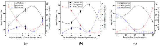
Figure 12.
Results of the one-factor test: (a) Results of a one-factor test on the angular velocity of the hill seeder; (b) results of a one-factor test on the inclination angle of the seed guide spoon; (c) results of a one-factor test on the length of the bridging groove.
3.2.2. Results of a One-Factor Test on the Inclination Angle of the Seed Guide Spoon
The performance curves of seed discharging at different inclination angles of the seed guide spoon are shown in Figure 12b. The qualification rate decreased, then increased, and finally decreased as the inclination angle of the seed guide spoon increased. The multiple rate gradually increased, then slowly decreased, and increased again as the inclination angle increased. The leakage rate tended to decrease as the inclination angle of the seed guide spoon increased. When the inclination angle of the seed guide spoon exceeded 70°, the leakage rate remained constant. At smaller inclination angles, the seed guide spoon picked up a smaller amount of seed, resulting in a higher leakage rate. Appropriately increasing the inclination angle of the seed guide spoon facilitated seed pickup. Therefore, the optimal inclination angle of the seed guide spoon was determined to be between 60° and 80°.
3.2.3. Results of One-Factor Test on Length of the Bridging Groove
The performance curves of seed discharge for different lengths of the bridging groove are shown in Figure 12c. The qualification rate first increased and then decreased as the length of the bridging groove increased. The multiple rate initially decreased and then stabilized. The leakage rate gradually increased and then rose more rapidly as the length of the bridging groove increased. The length of the bridging groove directly affected the seed clearing time. Longer bridging grooves resulted in longer seed clearing times and higher leakage rates, while shorter bridging grooves led to shorter seed clearing times and higher multiple rates. Therefore, an optimal range of 10–20 mm was determined for the length of the bridging groove.
3.3. Response Surface Test Results
The results of the response surface tests are shown in Table 4.
Table 4.
Results of the response surface test.
The results of the response surface tests were analyzed via regression analysis, as shown in Table 5. The regression model fit for the three test metrics was highly significant, and the lack-of-fit term was not significant (p > 0.05). This indicates that no other significant factors influenced the evaluation metrics.
Table 5.
Variance analysis of response surface test.
The regression equation after removing insignificant factors is:
The regression coefficient test yielded that the order of significance of the effects of the factors on the qualified rate was A, C, and B, the order of the multiple rate was A, B, and C, and the order of the leakage rate was C, B, and A.
According to the regression equation, surface graphs illustrating the effects of two interaction factors on the evaluation indices were generated, as shown in Figure 13. As seen in Figure 13a, the interaction between the angular velocity of the hill seeder and the inclination angle of the seed guide spoon significantly affected the qualified rate. With the increase in both the angular velocity of the hill seeder and the inclination angle of the seed guide spoon, the qualified rate first increased and then decreased. Figure 13b shows that the interaction between the length of the bridging groove and the inclination angle of the seed guide spoon had a highly significant effect on the multiple rate. As both the length of the bridging groove and the inclination angle of the seed guide spoon increased, the multiple rate first decreased and then increased. Figure 13c illustrates that the interaction between the angular velocity of the hill seeder and the inclination angle of the seed guide spoon significantly influenced the leakage rate. As the angular velocity of the hill seeder and the inclination angle of the seed guide spoon increased, the leakage rate first decreased and then increased. Finally, as shown in Figure 13d, the interaction between the inclination angle of the seed guide spoon and the length of the bridging groove had a highly significant effect on the leakage rate. As the inclination angle of the seed guide spoon and the length of the bridging groove increased, the leakage rate gradually increased.
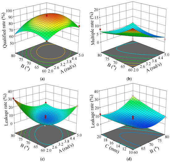
Figure 13.
Interaction surface diagram: (a) the interaction effect of A and B on the qualified rate; (b) the effect of interaction between A and B on multiple rate; (c) the interaction effect of A and B on the leakage rate; (d) the interaction effect of B and C on the leakage rate.
The key to improving seed discharge performance is achieving a reasonable match between the parameters. Therefore, the objective function and constraints for the multifactor optimization solution of the established quadratic regression model, incorporating the boundary conditions, are as follows:
The solution shows that the performance of the hill seeder is optimized at an angular velocity of 4.9 rad/s of the hill seeder, an inclination angle of 71.0° of the seed guide spoon, and a length of 10.9 mm of the bridging groove. At this time, the qualified rate, leakage rate, and multiple rate were 92.2%, 5.3%, and 2.6%, respectively.
3.4. Field Validation Test Results
Based on the results of the response surface test, the field test was carried out under the conditions that the angular velocity of the hill seeder was taken as 4.9 rad/s, the inclination angle of the priming spoon was taken as 71.0°, and the length of the overpass slot was taken as 10.9 mm, as shown in Figure 14.
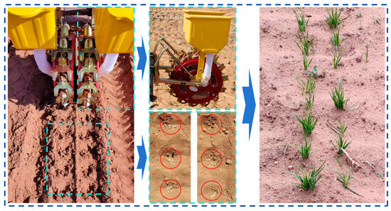
Figure 14.
Field test process and results. Red round inner flavour seed holes.
The results of the field validation tests are shown in Table 6. The errors between the field test results and the simulation results were −1.0%, −0.7%, and 1.6%, respectively. The errors were small, further validating the feasibility of using the discrete element method for simulation tests. Through the analysis of oat seedling emergence, it was found that the seed discharge performance of the variable-capacity spoon-type oat precision hill seeder met the agronomic requirements for oat planting. The hill seeder offers the advantages of a simple structure and low cost, making it suitable for widespread use in the oat-growing regions of Inner Mongolia, China. This could further promote the mechanization of oat-growing technology.
Table 6.
Field validation test results.
4. Discussion
Unlike field experiments, which are constrained by seasonal and environmental conditions, discrete element (DEM) simulations can be conducted at any time. Consequently, scholars have increasingly utilized simulations to model the seeding process [33,34]. In this study, DEM simulation was employed to optimize the structure and operating parameters of the hill seeder. The accuracy of the DEM simulation was validated through field trials, further demonstrating its feasibility in modeling the seeding process.
Analysis of the simulation results revealed that the angular velocity of the hill seeder directly affected both seed group mobility and seed clearing time. Improved seed group mobility enhances the seed filling performance of hill seeders, which is consistent with the findings of Li Hui et al. [14]. Longer seed clearing times increase the amount of seed cleared and impact discharge performance. When the angular velocity of the hill seeder is high, the centrifugal force on the seed in the metering scoop increases, hindering effective seed clearing. The inclination angle of the seed guide spoon and the length of the bridging groove also influence the seed filling and clearing performance of the hill seeder. Analysis of the seed filling force indicates that a smaller inclination angle of the seed guide spoon results in fewer seeds being picked up and a higher leakage rate after the seed clearing stage. Excessive inclination of the seed guide spoon leads to an increased number of seeds being picked up, and too many seeds create excessive interspecific friction, which impedes seed clearing. The length of the bridging groove directly affects seed clearing time. When the seed clearing time is too short, the seed passes through the clearing area before fully dropping, leading to inadequate clearing. Oat seeds, due to their fusiform shape, have their center of gravity outside the support point during filling and clearing. This phenomenon occurs randomly, causing significant fluctuations in the curves shown in Figure 12b,c.
Different geographical areas have varying nutrient and moisture content in the soil, and the seed requirements for crops that are not precision-sown in a single grain also differ. Conventional hill seeders are unable to directly adjust the seeding rate [11,12,13]. To address this, a variable-capacity spoon-type oat precision hill seeder was designed in this study. The seeding rate could be adjusted by changing the relative distance between the upper and lower seed metering spoons, which altered the volume of the seed metering cavity and, consequently, the amount of seed sown. The developed seeder could be adapted to seeding operations in plots with varying seeding volume requirements. Moreover, it has the potential to reduce oat seeding costs. However, the hill seeder is currently only suitable for oat sowing, which imposes certain limitations. Further research is needed to develop adaptable seed metering scoops capable of meeting the sowing requirements for a variety of crops.
The hill seeder developed in this study is more suitable for spindle-shaped seeds. However, seeds with high sphericity, such as soybeans, tend to roll along the bridging grooves directly into the seed metering spoon cavity, resulting in poor seed clearing and multiple seed placement. Additionally, machine vibrations under different working conditions, especially on uneven ground, can directly affect the filling and clearing performance.
5. Conclusions
(1) This study proposed the technical concept of controlling the seed quantity by using a variable-volume seed metering spoon. Based on this concept, a variable-capacity spoon-type oat precision hill seeder was designed to achieve uniform and stable sowing of oats.
(2) The working process of the hill seeder was simulated using the discrete element method, and the influence of various factors on its performance was analyzed. The optimal ranges for improved seed discharge performance were determined as follows: the angular velocity of the hill seeder, 3.5–5.5 rad/s; the inclination angle of the seed guide spoon, 60–80°; and the length of the bridging groove, 10–20 mm.
(3) Response surface tests were conducted to analyze the effects of the angular velocity of the hill seeder, the inclination angle of the seed guide spoon, and the length of the bridging groove on seed discharge performance. The results indicated that the optimal parameter combination was as follows: an angular velocity of 4.9 rad/s, an inclination angle of 71.0°, and a bridging groove length of 10.9 mm.
(4) Field validation tests were conducted using simulation-optimized parameters. The errors between the field test results and the simulation results were −1.0%, −0.7%, and 1.6%, respectively. The seeding qualified rate of the hill seeder was 91.2%, the leakage rate was 4.6%, and the multiple rate was 4.2%, which met the requirements for oat hole seeding.
(5) Future research should focus on investigating the effects of field operation vibrations on seed discharge performance, incorporating both simulation tests (through the adjustment of model parameters) and field tests (through comparative experiments). It is expected that these efforts will provide additional theoretical insights for the optimization of hill seeders.
Author Contributions
Conceptualization, W.D.; methodology, W.D.; software, W.D.; validation, X.Z.; formal analysis, D.X.; investigation, A.Z.; resources, F.L.; data curation, W.D. and Y.R.; writing—original draft preparation, W.D.; writing—review and editing, H.B. and X.K.; visualization, W.D., S.Y., and X.Y.; funding acquisition, F.L. All authors have read and agreed to the published version of the manuscript.
Funding
This research was funded by the National Natural Science Foundation of China (32060418), National Key Research and Development Program Project (2023YFD1600701), Inner Mongolia Autonomous Region Science and Technology Plan Project (2023YFHH0012), and Research Projects for First-class Discipline (YLXKZX-NND-046).
Institutional Review Board Statement
Not applicable.
Data Availability Statement
The available data are reflected in the original text.
Acknowledgments
We thank Wenjie Dong, a postdoctoral fellow at the Institute of Geology and Geophysics, Chinese Academy of Sciences, for his outstanding contribution to the revision of the English manuscript.
Conflicts of Interest
The authors declare no conflict of interest.
References
- Zhang, M.F.; Chen, Z.W.; Jia, J.Q.; Zhang, X.J.; Li, X.; Zhang, C.L.; Zhang, M.J.; Yang, W.D. Cloning of AP2/ERF transcription factor gene related to oat kernel covering. J. Shanxi Agric. Sci. 2020, 48, 658–663. [Google Scholar] [CrossRef]
- Liu, R.; Li, Y.J.; Liu, C.X.; Liu, L.J. Design and Experiment of Shovel Type Wide Seedling Belt Oat Seeding Furrow Opener. Trans. Chin. Soc. Agric. Mach. 2021, 52, 89–96. [Google Scholar] [CrossRef]
- Lu, Q.; Liu, L.J.; Zheng, D.C.; Liu, Z.J.; Zhao, J.H.; Wang, L. Research Progress of Mechanization Technology and Equipment in Whole Process of Oat Production. Trans. Chin. Soc. Agric. Mach. 2022, 53, 118–139. [Google Scholar] [CrossRef]
- Liu, C.L.; Li, F.L.; Jiang, M.; Huang, R.B.; Dai, L.; Gao, Z.P. Design and experiment of the spotting glue-paper tape precision seeder for small seed vegetables. Trans. Chin. Soc. Agric. Eng. 2022, 38, 20–29. [Google Scholar] [CrossRef]
- Liao, Y.T.; Zhang, B.X.; Zheng, J.; Liao, Q.X.; Liu, J.C.; Li, C.L. Design and Experiment of Pneumatic Needle PlanetaryGear Narrow-row Close Planting Precision Seed-metering Device. Trans. Chin. Soc. Agric. Mach. 2022, 53, 86–99. [Google Scholar] [CrossRef]
- Wu, S. Design and Research of 2BT-4 Type Buckwheat and Oatprecision Seeder; Shanxi Agricultural University: Taiyuan, China, 2022. [Google Scholar] [CrossRef]
- Yu, C.Y.; Chen, Z.; Chen, L.Q. Design and Test of Electronic Control Seeding System for Wheat Plot Drill. Trans. Chin. Soc. Agric. Mach. 2023, 54, 75–83. [Google Scholar] [CrossRef]
- Shang, S.Q.; Wu, X.F.; Yang, R.B.; Li, G.Y.; Yang, X.L.; Chen, B.Q. Research Status and Prospect of Plot-sowing Equipment and Technology. Trans. Chin. Soc. Agric. Mach. 2021, 52, 1–20. [Google Scholar] [CrossRef]
- Li, H.Q.; Yan, B.X.; Meng, Z.J.; Ling, L.; Yin, Y.X.; Zhang, A.Q.; Zhao, C.J.; Wu, G.W. Study on influencing factors of hole-filling performance of rice precision direct seed-metering device with hole ejection. Biosyst. Eng. 2023, 233, 76–92. [Google Scholar] [CrossRef]
- Zhang, Q.S.; Yu, Q.; Wang, L.; Liao, Y.T.; Wang, S.; Liao, Q.X. Design and Experiment of the Buckwheat Hill-Drop Planter Hole Forming Device. Trans. Chin. Soc. Agric. Mach. 2020, 51, 47–54+64. [Google Scholar] [CrossRef]
- Chen, Y.; Cheng, Y.; Chen, J.; Zheng, Z.; Hu, C.; Cao, J. Design and Experiment of the Buckwheat Hill-Drop Planter Hole Forming Device. Agriculture 2021, 11, 1085. [Google Scholar] [CrossRef]
- Zhang, G.Z.; Zhang, S.S.; Yang, W.P.; Lu, K.; Lei, Z.Q.; Yang, M. Design and experiment of double cavity side-filled precision hole seed metering device for rice. Trans. Chin. Soc. Agric. Eng. 2016, 32, 9–17. [Google Scholar] [CrossRef]
- Shi, L.R.; Zhao, W.Y. Design and test of rolling spoon type flaxes precision hole sower for caraway in northwest cold and arid agricultural region. J. Jilin Univ. (Eng. Technol. Ed.) 2023, 53, 2706–2717. [Google Scholar] [CrossRef]
- Li, H.; Zhao, W.Y.; Shi, L.R.; Dai, F.; Rao, G.; Wang, Z. Design and Test of Seed Ladle Tongue Type Flax Precision Burrow Planter. Trans. Chin. Soc. Agric. Mach. 2024, 55, 85–95. [Google Scholar] [CrossRef]
- Wang, L.; Liao, Y.T.; Li, M.L.; Ren, N.; Zheng, X.M.; Wang, M.Z.; Liao, Q.X. Motion characteristics of rapeseeds and wheat seeds within mixing components of air-assisted centralized metering device based on DEM-CFD. Comput. Electron. Agric. 2024, 221, 10896. [Google Scholar] [CrossRef]
- Wang, Y.X.; Huang, S.T.; Zhang, W.Y.; Qi, B.; Zhou, X.Z.; Ding, Y.Q. Design and Experiment of Wheat Precision Seed Metering Device with Staggered Hook-tooth. Trans. Chin. Soc. Agric. Mach. 2024, 55, 142–153+167. [Google Scholar] [CrossRef]
- Gao, X.J.; Yu, L.Y.; Wu, X.P.; Huang, Y.X.; Yan, X.L. Design and Experiment of Intelligent Seed Supply System of Air-assisted High Speed Precision Maize Seed Metering Device. Trans. Chin. Soc. Agric. Mach. 2023, 54, 66–75. [Google Scholar] [CrossRef]
- Dong, J.X.; Zhang, S.L.; Zheng, Z.Z.; Wu, J.T.; Huang, Y.X.; Gao, X.J. Development of a novel perforated type precision metering device for efficient and cleaner production of maize. J. Clean. Prod. 2024, 443, 140928. [Google Scholar] [CrossRef]
- Dun, G.; Wei, Y.; Ji, X.; Gao, S.; Pei, Y.; He, Y.; Ma, C. Design and Test of the Outside-Filling Chinese Chive Adjustable-Capacity Precision Seed-Metering Device. Agronomy 2025, 15, 622. [Google Scholar] [CrossRef]
- Ll, W.; Xu, H.; Li, X.H.; Li, H.; Yu, Y.C. Design and Experiment of Soybean Side Nest Seed Meter Based on EDEM. J. Agric. Mech. Res. 2023, 45, 164–169. [Google Scholar] [CrossRef]
- Ding, L.; Dou, Y.F.; Wang, W.Z.; Xu, Y.F.; He, X.; Qu, Z. Design and Experiment of Seed Metering Device with Combination Hole and Inner Filling for Cyperus esculentus. Trans. Chin. Soc. Agric. Mach. 2022, 53, 100–115. [Google Scholar] [CrossRef]
- Zheng, G.; Qi, B.; Zhang, W.; Shao, W.; Zhang, L.; Wang, Y.; Ding, Y. Engineering Discrete Element Method-Based Design and Optimization of the Key Components of a Spoon-Wheel Spinach Seed-Metering Device. Agronomy 2024, 14, 2096. [Google Scholar] [CrossRef]
- Gao, X.J.; Cui, T.; Zhou, Z.Y.; Yu, Y.B.; Xu, Y.; Zhang, D.X.; Song, W. DEM study of particle motion in novel high-speed seed metering device. Adv. Powder Technol. 2021, 32, 1438–1449. [Google Scholar] [CrossRef]
- Hu, H.J.; Zhou, Z.L.; Wu, W.C.; Yang, W.H.; Li, T.; Chang, C.; Ren, W.J.; Lei, X.L. Distribution characteristics and parameter optimisation of an air-assisted centralised seed-metering device for rapeseed using a CFD-DEM coupled simulation. Biosyst. Eng. 2021, 208, 246–259. [Google Scholar] [CrossRef]
- Walunj, A.; Chen, Y.; Tian, Y.; Zeng, Z. Modeling Soil–Plant–Machine Dynamics Using Discrete Element Method: A Review. Agronomy 2023, 13, 1260. [Google Scholar] [CrossRef]
- Zhao, X.; Zhang, T.; Liu, F.; Li, N.; Li, J. Sunflower Seed Suction Stability Regulation and Seeding Performance Experiments. Agronomy 2023, 13, 54. [Google Scholar] [CrossRef]
- Albasheer, A.H.; Liao, Q.; Wang, L.; Ibrahim, E.J.; Xiao, W.; Li, X. Design and Optimization of Divider Head Geometry in Air-Assisted Metering Devices for Enhanced Seed Distribution Accuracy. Agronomy 2025, 15, 769. [Google Scholar] [CrossRef]
- Zhou, H.; Dai, F.; Shi, R.; Zhao, C.; Deng, H.; Pan, H.; Zhao, Q. Simulation and Optimization of a Pendulum-Lever-Type Hole-Seeding Device. Agriculture 2024, 14, 750. [Google Scholar] [CrossRef]
- Wu, W.C.; Deng, X.; Li, J.; Hu, J.F.; Cheng, H.; Zhou, W.; Deng, F.; Chen, Y.; Ren, W.J.; Lei, X.L. Micro-level stress characteristics of rapeseed particle during the seeding process using the MFBD-DEM coupled method. Comput. Electron. Agric. 2024, 220, 108929. [Google Scholar] [CrossRef]
- Dong, W.X.; Li, N.; Liu, F.; Zhao, X.; Wang, L.H.; Xuan, D.Z.; Zhong, W.D.; Hu, H.T.; Meng, X.Y.; Li, M.Y.; et al. Study on vibration adsorption characteristics of small-particle-size seeds based on DEM. INMATEH—Agric. Eng. 2023, 71, 3. [Google Scholar] [CrossRef]
- He, S.Y.; Qian, C.; Jiang, Y.C.; Qin, W.; Huang, Z.S.; Huang, D.M.; Wang, Z.M.; Zang, Y. Design and optimization of the seed feeding device with DEM-CFD coupling approach for rice and wheat. Comput. Electron. Agric. 2024, 219, 108814. [Google Scholar] [CrossRef]
- Gu, B.; Hu, C.; Xing, J.; He, X.; Wang, X.; Ren, K.; Wang, L. Establishment of a Discrete Element Model for Wheat Particles Based on the Ellipsoidal Method and CFD–DEM Coupling. Agriculture 2025, 15, 369. [Google Scholar] [CrossRef]
- Tang, H.; Xu, F.D.; Xu, C.S.; Zhao, J.L.; Wang, Y.J. The influence of a seed drop tube of the inside-filling air-blowing precision seed-metering device on seeding quality. Comput. Electron. Agric. 2023, 204, 107555. [Google Scholar] [CrossRef]
- Hui, Y.; Huang, C.; Liao, Y.; Wang, D.; You, Y.; Bai, X. The Medium-Blocking Discharge Vibration-Uniform Material Plasma Seed Treatment Device Based on EDEM. Agronomy 2023, 13, 2055. [Google Scholar] [CrossRef]
Disclaimer/Publisher’s Note: The statements, opinions and data contained in all publications are solely those of the individual author(s) and contributor(s) and not of MDPI and/or the editor(s). MDPI and/or the editor(s) disclaim responsibility for any injury to people or property resulting from any ideas, methods, instructions or products referred to in the content. |
© 2025 by the authors. Licensee MDPI, Basel, Switzerland. This article is an open access article distributed under the terms and conditions of the Creative Commons Attribution (CC BY) license (https://creativecommons.org/licenses/by/4.0/).