Article

Design of and Experimentation on an Intelligent Intra-Row Obstacle Avoidance and Weeding Machine for Orchards

by
Weidong Jia
1,2,
Kaile Tai
1,2,
Xiang Dong
1,2,
Mingxiong Ou
1,2 and
Xiaowen Wang
1,2,*
1
School of Agricultural Engineering, Jiangsu University, Zhenjiang 212013, China
2
High-Tech Key Laboratory of Agricultural Equipment and Intelligence of Jiangsu Province, Jiangsu University, Zhenjiang 212013, China
*
Author to whom correspondence should be addressed.
Agriculture 2025, 15(9), 947; https://doi.org/10.3390/agriculture15090947
Submission received: 21 March 2025 / Revised: 23 April 2025 / Accepted: 25 April 2025 / Published: 27 April 2025
(This article belongs to the Special Issue Agricultural Machinery and Technology for Fruit Orchard Management)

Abstract

:
Based on the current issues of difficulty in clearing intra-row weeds in orchards, inaccurate sensor detection, and the inability to adjust the row spacing depth, this study designs an intelligent intra-row obstacle avoidance and weeding machine for orchards. We designed the weeding machine’s sensor device, depth-limiting device, row spacing adjustment mechanism, joystick-based obstacle avoidance mechanism, weeding shovel, and hydraulic system. The sensor device integrates non-contact sensors and a mechanical tactile structure, which overcomes the instability of non-contact detection and avoids the risk of collision obstacle avoidance by the weeding parts. The weeding shovel can be adapted to the environments of orchards with small plant spacing. The combination of the sensor device and the obstacle avoidance mechanism realizes flexible obstacle avoidance. We used Ansys Workbench to conduct static and vibration modal analyses on the chassis of the in-field weeding machine. On this basis, through topology optimization, the chassis quality of the weeding machine is reduced by 8%, which realizes the goal of light weight and ensures the stable operation of the machinery. To further optimize the weeding operation parameters, we employed the Box–Behnken design response surface analysis, with weeding coverage as the optimization target. We systematically explored the effects of forward speed, hydraulic cylinder extension speed, and retraction speed on the weeding efficiency. The optimal operational parameter combination determined by this study for the weeding machine is as follows: forward speed of 0.5 m/s, hydraulic cylinder extension speed of 11.5 cm/s, and hydraulic cylinder retraction speed of 8 cm/s. Based on the theoretical analysis and scenario simulations, we validated the performance of the weeding machine through field experiments. The results show that the weeding machine, while exhibiting excellent obstacle avoidance performance, can achieve a maximum weeding coverage of 84.6%. This study provides a theoretical foundation and technical support for the design and development of in-field mechanical weeding, which is of great significance for achieving intelligent orchard management and further improving fruit yield and quality.

1. Introduction

Effective weed management in orchards can prevent weeds from competing with trees for nutrients, water, and sunlight, which has a positive impact on yield and quality [1,2,3,4]. The current main methods of orchard weeding can be categorized into chemical weeding [5] or non-chemical weeding [6,7,8,9]. Chemical weeding is usually easy to operate and highly efficient, but it may pose potential health and ecological risks to both crops and the environment. Over-reliance on chemical herbicides can lead to increased weed resistance, significantly reducing the effectiveness of weed control [10,11]. Herbicide residues can also harm a large number of non-target organisms, leading to the death of pest predators and other beneficial species [12,13,14]. Therefore, chemical weeding methods are used cautiously in many parts of the world, especially in orchards whose managers advocate for a transition to organic production methods and regions with strict environmental management policies, such as the European Union [15]. Among the non-chemical weeding methods, manual weeding, either by hand or using handheld electric tools, remains the main method of weed management in regions with low levels of agricultural mechanization or where the orchard size is limited. However, manual weeding is a typical labor-intensive task, and considering labor costs, it may be a more tedious and expensive method of weeding [1]. Therefore, the commonly adopted non-chemical weeding method is mechanical weeding. Mechanical weeding not only effectively reduces labor intensity and improves weeding efficiency but also performs functions such as loosening the soil, conserving moisture, and reducing pest and disease risks [16,17].
Orchard weeds include inter-row and intra-row weeds. Due to fruit trees’ requirements of light and ventilation and the convenience of their management, orchards usually have inter-row spaces that have a fixed width, relatively straight paths, and good accessibility, making inter-row weeds easier to control effectively. However, due to the presence of fruit trees, controlling intra-row weeds using non-chemical methods is often more challenging. It is difficult to effectively control weeds in the intra-row areas of orchards without causing damage to fruit trees or leading to yield reduction [18]. Many studies have shown that as the distance between trees and weeds decreases, competition for resources intensifies, significantly affecting trees’ productivity and profitability [19,20]. Therefore, the design and development of intra-row mechanized weeding equipment has become a focus of research for many scholars. Reiser et al. (2019) combined an electric rotary tiller weeding machine with an autonomous tracked robot, using sonar sensors or mechanical rods to detect tree trunks and linear motors to achieve obstacle avoidance for the weeding components [21]. The machine performed well in specific laboratory environments but faced challenges in field experiments, such as closely spaced tree trunks, leaf obstructions, and missing trunks, which prevented the weeding components from operating within rows. Experiments revealed that the intra-row spacing of grapevines is not always suitable for a 0.3 m diameter electric weeding component, as some spaces between trunks are too narrow to accommodate the component. Lei et al. (2022) developed a single-sided obstacle-avoiding mower for Y-shaped pear orchards, in which the mowing disk is positioned using a profiling mechanism, operated by a hydraulic system, and avoids obstacles passively through springs [22]. Comparative tests showed that the machine is approximately five times more efficient than a shoulder-mounted weeding machine and 20 times more efficient than manual weeding. Shoulder-mounted weeding machines and manual weeding are both manual approaches, with the cutting height controlled subjectively by the operator, leading to fatigue during prolonged operation, which significantly affects the accuracy of weeding. The weeding machine is efficient and operates stably, but during its operation, the mowing disk makes direct contact with the crops, which may cause damage or destruction if used on crops with relatively thin roots. Jiang et al. (2023) developed an intra-row weeding system that first identifies weeds and locates crops using vision and then drives the weeding components with a cylinder for intra-row weeding operations [23]. The vision system achieves an accuracy rate of over 90%, with indoor tests demonstrating the robustness and effectiveness of the automated intra-row weed control system. The equipment has not yet undergone outdoor testing, and outdoor tests involve many uncertainties, so the stability of the vision system requires further analysis. Applying this method to grape crops may pose challenges, as leaves on grapevines might partially or completely obscure crop rows, affecting the accuracy of the vision system. Assirelli et al. (2015) tested photoelectric diffuse reflection sensors and capacitive sensors for detecting crop rows, and the detection equipment accurately identified poplar cuttings at the same speed as standard mechanical weeders [24]. Tests proved that the sensor is suitable for installation in intra-row weeding machine. However, the sensor has some limitations, as its detection distance is less than 25 cm, requiring it to be as close to the crops as possible for effective detection in practical use. In summary, the environmental adaptability of the sensor is the core of the sensing system, which needs to be dynamically adjusted according to the light, shading and terrain characteristics of the operating scene. During the working process, the sensor monitors the positions of obstacles and feeds the data back to the control system. According to the signal of the control system, the obstacle avoidance and weeding device uses the hydraulic system or electric system as the driving source to provide power to control the movement of the working parts, preventing the weeding parts from colliding with crops or other obstacles.
For countries and regions, including China, which have long advocated for agricultural sustainability strategies, it is crucial to enhance agricultural production efficiency and ecological effects while promoting the use of clean energy and reducing carbon emissions during the production process [25,26]. An intelligent intra-row weeding machine that can operate in typical orchards is of great importance for non-chemical weed management and ensuring fruit tree yields. Therefore, the aim of this study was to design an intelligent intra-row obstacle avoidance and weeding machine for orchards. (1) The machine consists of sensor technology, a row width adjusting device, weeding parts, a hydraulic system, etc., and is used to remove weeds in fruit trees. The sensor system can accurately detect fruit trees and achieve precise obstacle avoidance. (2) Static and vibrational modal analyses were performed on the chassis of the intra-row weeding machine using Ansys Workbench to verify whether it meets the operational requirements, and the topology optimization module was applied to achieve a lightweight design. (3) The performance of the smart in-row obstacle avoidance mowing machinery was validated through field trials, and the optimization potential of the operating parameters was analyzed in depth based on the test results to explore the possibility of further improving the performance of the weeding machinery.

2. Materials and Methods

2.1. Design, Functions, and Working Principles

2.1.1. Technical Approach and Power Flow Analysis

To ensure the normal operation of various components, this study designs the system through the technical approach (Figure 1) and power flow diagram (Figure 2) described below. The main components required for the weeding machine’s operation include the sensor system, intra-row obstacle avoidance system, weeding blades, chassis, and double-acting hydraulic cylinders. The power is supplied by the tractor’s output shaft.

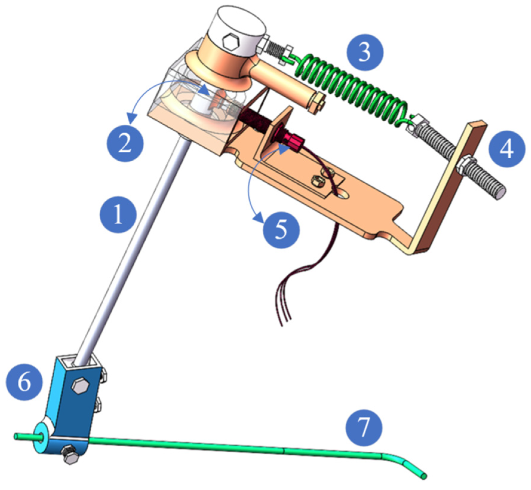
2.1.2. Sensor System

As shown in Figure 3, the touch rod (7) is connected to the rebound shaft (1) by the clamping device (6), and the protruding length of the touch rod (7) can be adjusted by the tightening or loosening of the screws in the clamping device (6) to suit the length of the intra-row weeding tool. The rebound shaft (1) is connected to the tension adjustment device (4) via the hook spring (3), and the pre-tension of the hook spring (3) can be adjusted by loosening or tightening the screws of the tension adjustment device (4). When an obstacle obstructs the touch rod (7), the rebound shaft (1) rotates. When the bump (2) on the rebound shaft (1) rotates to the detection range of the photoelectric sensor (5), the sensor’s electrical signal changes and is transmitted to the control system. When the touch rod (7) avoids the obstacle, the hook spring (3) drives the rebound shaft (1) to reset the touch rod (7). The bump (2) on the rebound shaft (1) also resets, and the electrical signal of the photoelectric sensor (5) returns to its original state. The function of the sensor system is to detect grapevines or other obstacles. In this way, the weeding machine can accurately identify obstacles in the row, respond accordingly, and drive the intra-row weeding device to avoid them. The elasticity coefficient of the hook spring (3) directly affects the contact force between the touch rod and the fruit tree. If the contact force is too large, it may exceed the bending load capacity of the tree trunk, causing damage to or even breakage of the tree [27]. To ensure that the touch rod (7) does not exert excessive contact force on the fruit tree, as shown in Figure 4, the elasticity coefficient K of the hook spring (3) must meet the following condition:
l 1 = l 5 + l 6 l 2 = ( l 1 + l 2 ) 2 + ( l 3 2 ) 2 2 ( l 1 + l 2 ) ( l 3 2 ) cos θ 1 l 4 = R · sin ( π arcsin ( l 1 + R ) · sin θ 1 l 2 ) K F · l 3 l 2 l 5 · l 4

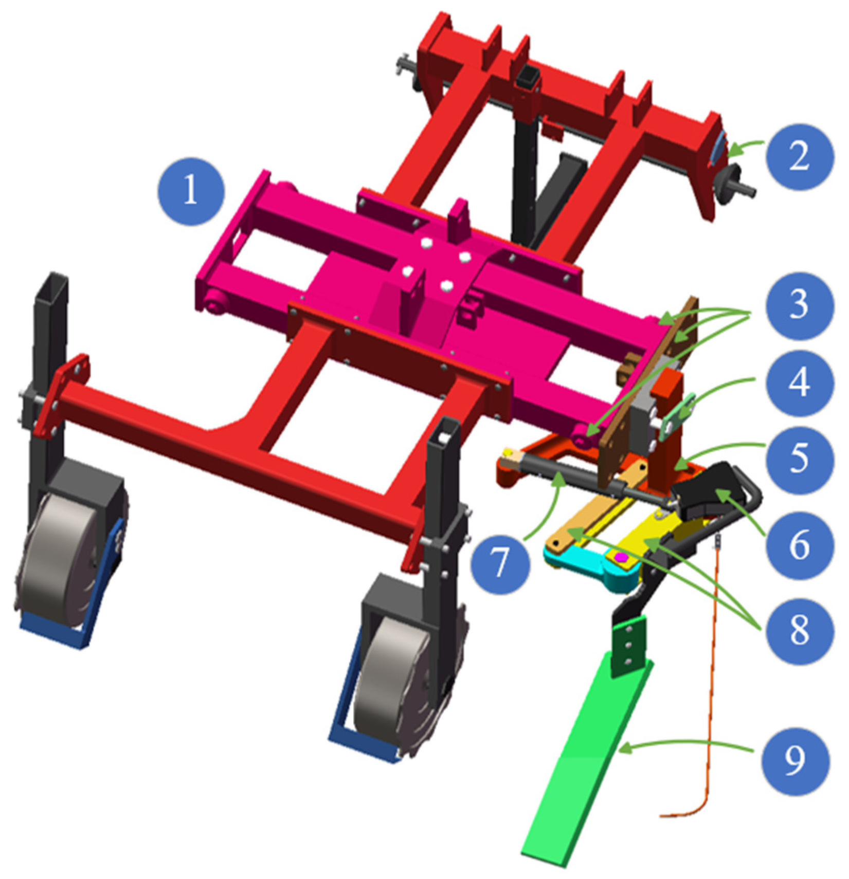
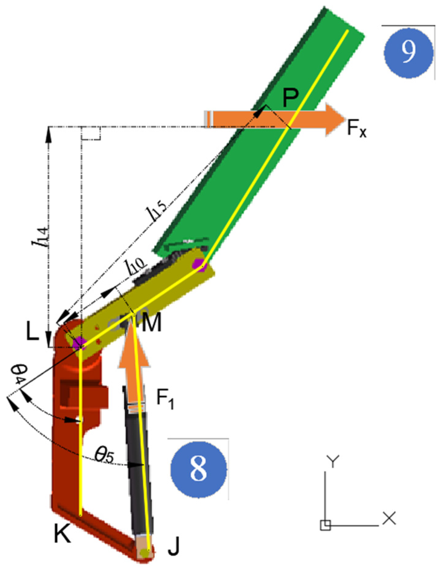
2.1.3. Functions and Working Principles of Key Components

As shown in Figure 5, the three-point hitch (2) is used to connect the tractor to the intra-row weeding machine. The chassis (1) is used to support and fix various components, ensuring their stability and functionality. The distance adjustment device (3) is embedded within the chassis (1), and after loosening the screws on both sides, its extension can be pulled out. Since the intra-row weeding device is indirectly fixed to the distance adjustment device (3), this method allows for adjustment of the working distance between the chassis (1) and the grape row, without changing the relative position of the intra-row weeding device to the grape row. The clamping device (4) fixes the connection frame (5) through a plate clamp method, and the tightening or loosening of the plate clamp allows the up-and-down movement of the connection frame (5), which can control the working depth of the weeding shovel (9). During the intra-row weeding operation, the double-acting hydraulic cylinder (7) extends the push rod. When the touch rod encounters an obstacle, the control system collects the changed electrical signals, causing the electromagnetic valve to reverse, retracting the push rod of the double-acting hydraulic cylinder (7), which drives the rocker mechanism (8) to rotate and indirectly drives the weeding shovel (9) to perform obstacle avoidance in the row. Once the obstacle avoidance is completed and the touch rod resets, the control system collects the original electrical signal, causing the electromagnetic valve to reverse again, and the push rod of the double-acting hydraulic cylinder (7) extends once more, indirectly driving the weeding shovel (9) to resume work in the row. As shown in Figure 6, since the length of the hydraulic cylinder and its push rod directly affects the working position of the weeding shovel, an analysis of the size l9 of the double-acting hydraulic cylinder is required, and the formula derivation is as follows.
θ 3 = θ 2 + arcsin ( l 13 l 12 ) arctan ( l 7 l 8 ) π 2 l 9 = l 10 2 + l 7 2 + l 8 2 2 · l 10 · l 7 2 + l 8 2 . cos θ 2

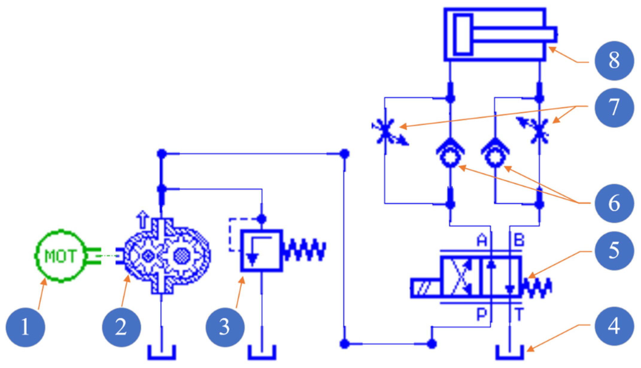
2.1.4. Hydraulic System

As shown in Figure 7, in this hydraulic system, the tractor’s output shaft (1) is connected to the gear pump (2) via a coupling, providing power to the pump. The gear pump (2) extracts hydraulic oil from the tank (4), converting mechanical energy into hydraulic energy, thereby supplying continuous high-pressure fluid to the hydraulic system. To regulate the pressure of the hydraulic system and ensure its safety, an overflow valve (3) is installed at the outlet of the gear pump (2). The two-position four-way directional valve (5) is used to control the flow direction of the hydraulic oil, thereby adjusting the telescopic motion of the push rod of the double-acting hydraulic cylinder (8). A check valve (6) and a throttle valve (7) are installed on the A and B outlet pipelines of the two-position four-way directional valve (5) to regulate the retraction and extension speeds of the push rod of the double-acting hydraulic cylinder (8). During intra-row operations, the double-acting hydraulic cylinder (8) drives the weeding shovel to overcome soil resistance in order to meet the normal working requirements. As shown in Figure 8, the push rod of the double-acting hydraulic cylinder (8) mainly needs to overcome the resultant resistance force in the X direction from the soil acting on the weeding shovel (it is assumed that the machine translates in the negative direction along the X-axis for weeding operations.) [28]. The following is an analytical estimation of the thrust force F1 required by the double-acting hydraulic cylinder (8):
l 15 = ( l 11 ) 2 + ( l 12 2 ) 2 2 ( l 11 ) · ( l 12 2 ) · cos θ 2 l 14 = l 15 × sin ( θ 4 arcsin l 12 2 × sin θ 2 l 15 ) F 1 = F x × l 14 l 10 × sin θ 5

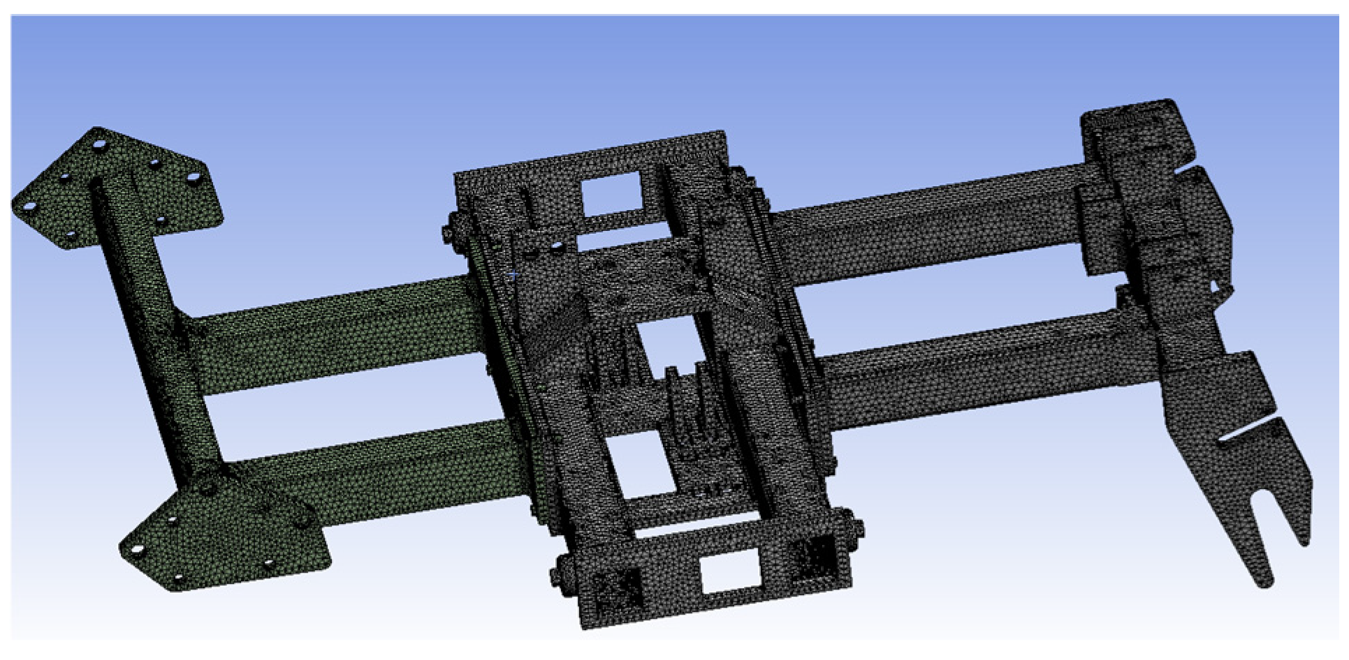
2.2. Finite Element Model of the Chassis

2.2.1. Ansys and SolidWorks

FEA simulates real physical systems (including geometry and loading conditions) using mathematical approximation methods, providing solutions for complex engineering problems. Ansys (Version 2022, ANSYS Inc., America), as a leading finite element simulation analysis software, provides an integrated design environment capable of simulating multiple physical fields and their couplings, including structure, vibration, heat, fluid, electromagnetic fields, circuits, systems, and chips. It is widely used in fields such as aerospace, mechanical manufacturing, energy, automotive transportation, defense, electronics, civil engineering, shipbuilding, and light industry [29,30,31,32]. Ansys, through integrated analysis tools, helps engineers comprehensively assess and optimize products from multiple perspectives during the product development process. By simulating different working conditions and loading scenarios, users can predict various situations that products may encounter in actual use, thereby identifying potential issues in advance, optimizing design solutions, and avoiding large-scale physical tests during the experimental phase, saving time and costs. Additionally, Ansys’ post-processing capabilities are powerful, allowing detailed visualization of simulation results, helping engineers clearly understand key data such as strain, stress, temperature distribution, and fluid flow. This visualization feature enables designers to intuitively identify potential weak points and adjust the design based on data feedback, improving product performance and reliability.
SolidWorks (Version 2020, Dassault systemes company, America) is a comprehensive 3D computer-aided design software platform. It provides a full range of tools, from part modeling to assembly design, supports parametric modeling, and helps designers efficiently build complex structural models through sketching and feature definitions. After the design is completed, SolidWorks supports export of the model to various formats (such as STEP, IGES, Parasolid, etc.), making it easier to integrate with other simulation software. For example, Ansys’ preprocessing module can import .STEP files and then further perform finite element analysis and structural optimization.

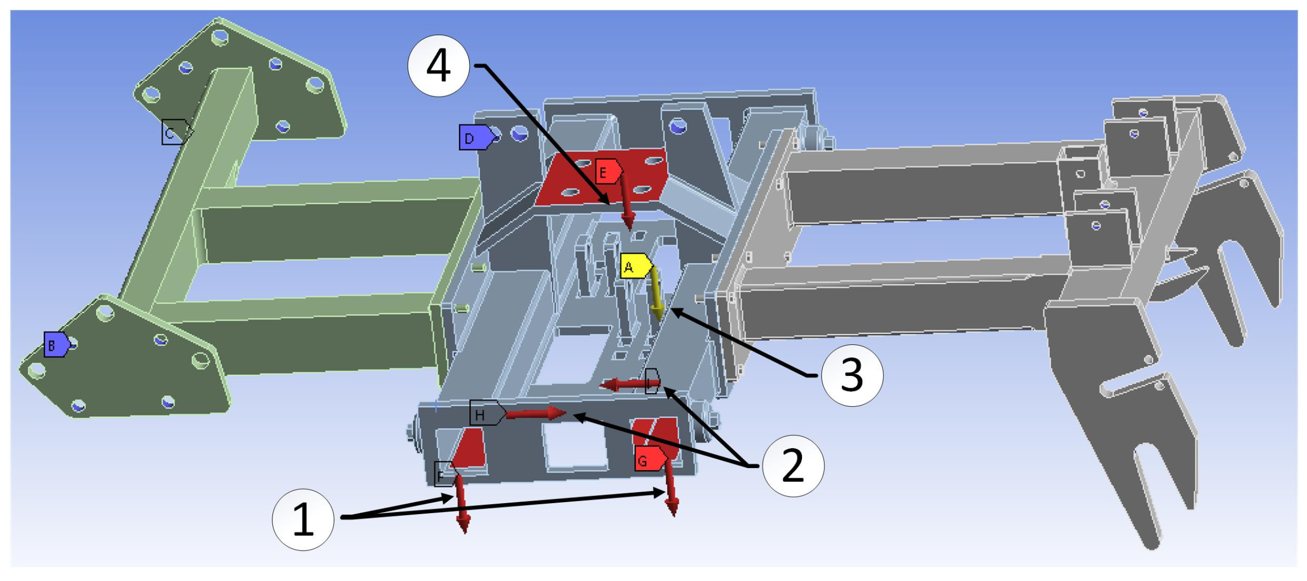
2.2.2. Simulation and Preprocessing

The model of the intra-row weeding machine chassis is shown in Figure 9. The dimensions of the intra-row weeding machine chassis are 1355 mm in length, 1032 mm in width, and 453 mm in height. The chassis of the intra-row weeding machine is divided into three parts, front, middle, and rear, which are fixed together by double-row bolts. The focus of this section is on performing stress–strain finite element analysis and vibration modal analysis on the original chassis model using Ansys software, aiming to minimize structural flexibility and maximize natural frequencies. A lightweight topology optimization design was applied, followed by model reconstruction and re-analysis of static and vibration modes [33]. First, the chassis was modeled in SolidWorks, and then it was imported into the Ansys static analysis module in .stp format. The material is structural steel with a Young’s modulus of 211 GPa, a Poisson’s ratio of 0.3, a density of 7850 kg/m3, and a yield strength of 250 MPa. Due to features such as through-holes, stiffeners, fillets, and arcs in the bracket model, it was difficult to use hexahedral meshing. Considering the computation time and solution accuracy, the chassis was meshed using the patch conforming method with tetrahedral elements, as shown in Figure 10. The mesh size was set to 4 mm, with a total of 671,180 nodes and 359,402 mesh elements. The average mesh quality was 0.707, the Jacobian ratio (corner nodes) was 0.974, and the Jacobian ratio (Gauss points) was 0.987. This indicates good mesh quality, meeting the requirements for simulation analysis [34].
In structural analysis, correctly setting the fixed support areas is crucial for ensuring the accuracy of the analysis results. To simulate real working conditions, the support through-hole area at the rear end of the chassis and the three-point suspension through-hole area are defined as fixed supports to reflect the actual connection method. Based on actual operating conditions, the load application model is simplified, and the chassis’ stress situation mainly considers several aspects: (1) the self-weight load of the fuel tank and other related components at the top of the chassis, with a load value of approximately 1540 N; (2) the self-weight load of the in-field weeding components on the chassis, with a load value of approximately 586 N; (3) the soil resistance load, with a maximum load value of approximately 3000 N; (4) the impact of Earth’s gravity. The distribution of the load is shown in Figure 11.

2.3. Field Experiment

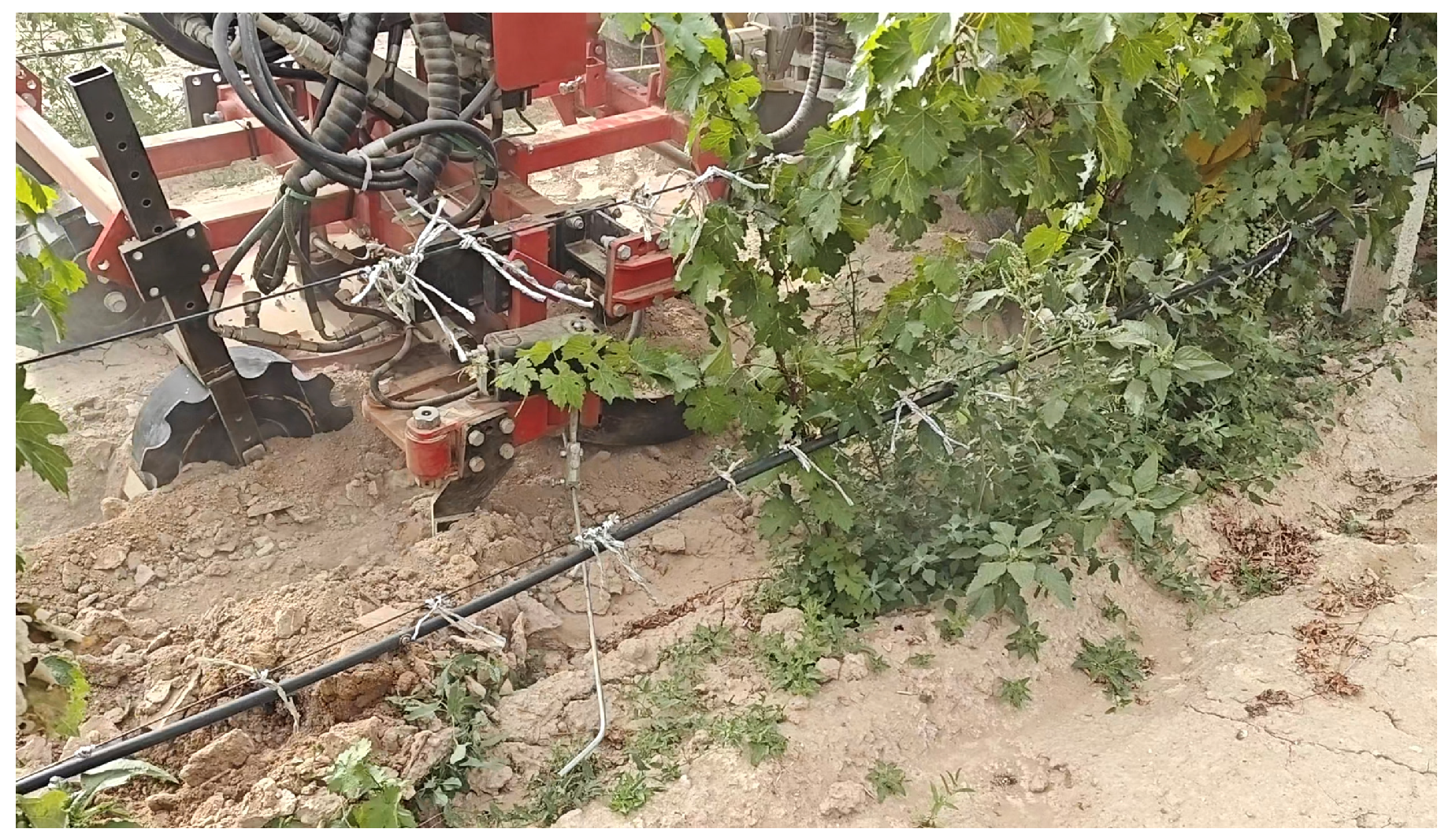
2.3.1. Experimental Conditions

The main objectives of this field experiment were to evaluate the weeding performance of the in-field weeding machine in a double trellis vineyard and its optimization potential regarding operational parameters, observe potential issues during operation, and provide data support and improvement suggestions for the practical application of this technology. The field experiment was conducted in August 2024 in a vineyard in Hongsibao, Wuzhong City, Ningxia Hui Autonomous Region. It was determined that the row spacing of the double trellis vineyard is approximately 4000 mm, the plant spacing is about 700 mm, and the average diameter of the grapevines is around 20 mm. The soil type in the orchard is light gray calcareous soil, with a high percentage of powder particles and relatively low content of sand and clay particles. This soil has strong water-retention and nutrient-holding capabilities, with a large number of capillary pores. The types of weeds in the experimental field include Amaranthus retroflexus, wild lettuce, goosefoot, and crabgrass, among others. The instruments and equipment required for the experiment include an intra-row weeding machine prototype, a Dongfanghong tractor (model MF804-G4, YTO Group corporation, Luoyang City, China), measuring tape, stopwatch, computer, camera, camera stand, etc. The measuring tape is used to measure the forward distance traveled by the tractor, and the camera stand base is fixed to the chassis, with the other end securing the camera to record the operation process in real time. The computer is responsible for processing the video data and analyzing the operational effects. The working status of the intra-plant weeding equipment is shown in Figure 12. The intra-row weeding machine is mounted behind the tractor using a three-point suspension system, as shown in Figure 13.

2.3.2. Experimental Scheme

Based on the Box–Behnken design response surface analysis, a combination experimental scheme with three factors and three levels was selected (Table 1), using machine forward speed, hydraulic cylinder return speed, and hydraulic cylinder extension speed as experimental factors [35,36,37]. In total, 17 experimental groups were conducted, with a set travel distance of 15 m for each group. For each group, three weed control coverage results were obtained, and the average of the three test results was taken as the weed control coverage for that group. If the grapevine was scratched, broken, or uprooted during the process of weeding in the row, it was considered to have damaged the grapevine. Analysis shows that when the hydraulic cylinder retraction speed is less than 70 mm/s and the forward speed is greater than 600 mm/s, the weeding shovel is prone to collide with grapevines, causing damage [37]. Meanwhile, too low an extension speed for the hydraulic cylinder leads to large areas of weed control omissions, while too high an extension speed has a limited effect on improving weed control coverage. The final determination of the hydraulic cylinder return speed range is 70–90 mm/s, the machine forward speed range is 400–600 mm/s, and the hydraulic cylinder extension speed range is 85–105 mm/s.
The schematic diagram of the work is shown in Figure 14, and the calculation formulas for each experimental indicator are as follows:
W C = ( 1 M A W D × S R ) × 100 %
O A = U D T N × 100 %
Note: WC (%) is the weeding operation coverage rate. MA (mm2) is the area of weeding omissions in the region. WD is the weeding width within the row (350 mm). SR is the distance between adjacent grapevines (700 mm). OA (%) is the obstacle avoidance rate. TN (plants) is the total number of grapevines in each experimental group. UD (plants) is the number of undamaged grapevines.

3. Results

3.1. Results and Analysis of Finite Element Simulation

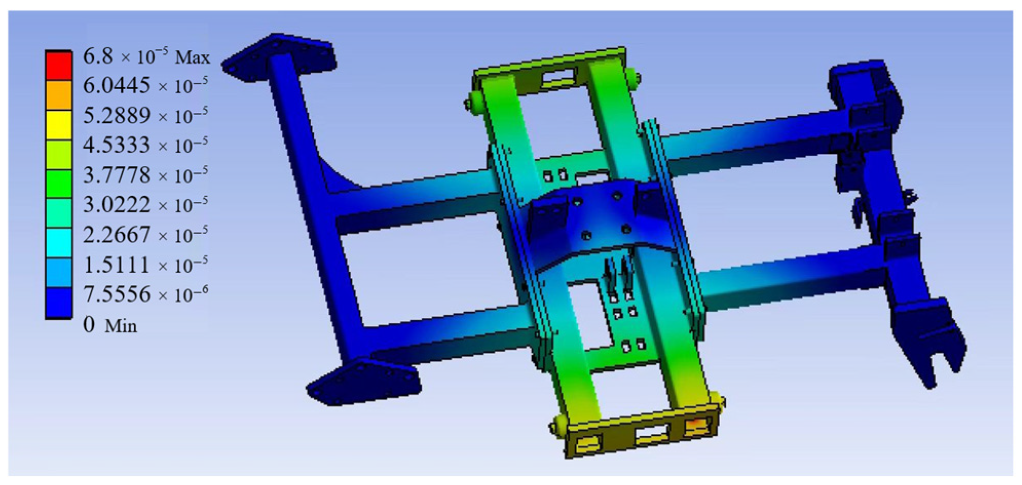
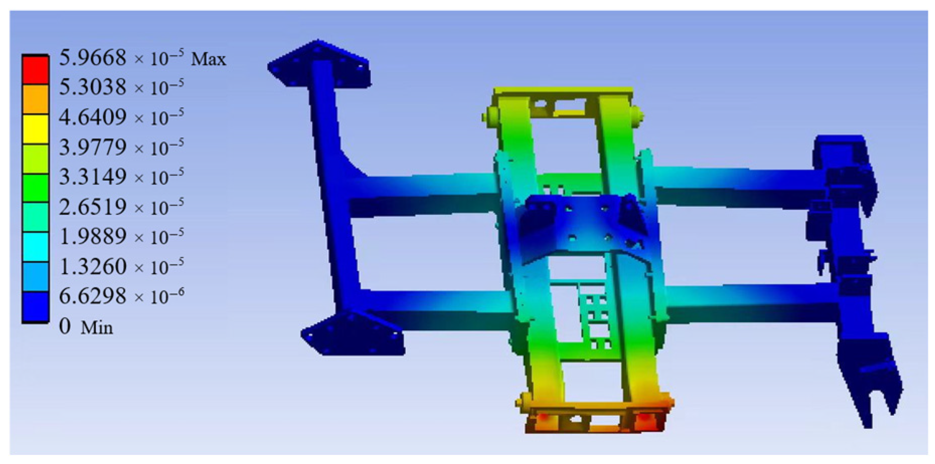
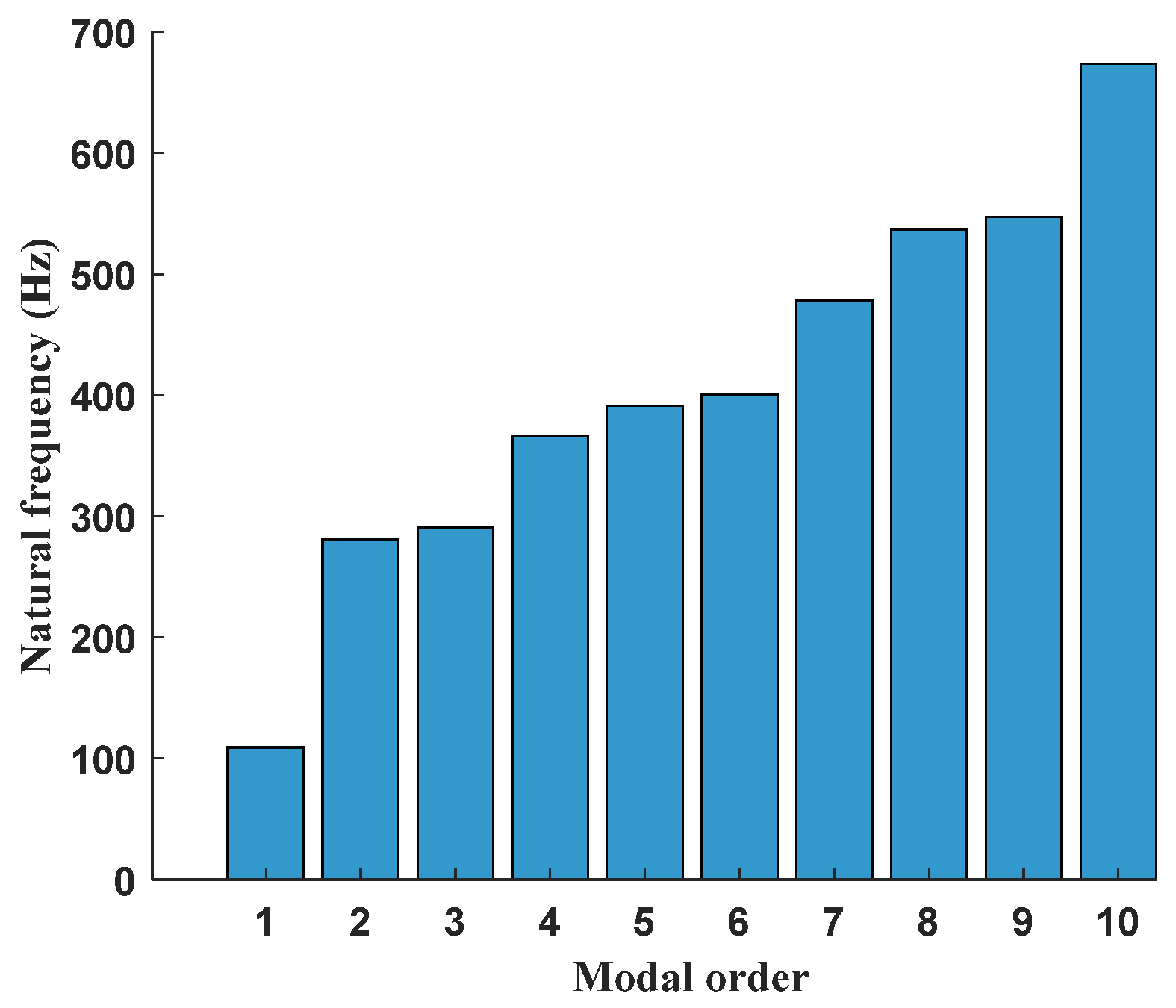
3.1.1. Static and Modal Analysis of the Chassis

Analyzing the structure’s response under static loads helps to evaluate its stiffness, load-bearing capacity, and safety. By calculating the structure’s deformation, stress distribution, etc., static analysis can identify potential weak points, guide design optimization, and ensure the structure’s reliability and durability under actual working conditions. After the calculations, the deformation and stress contour maps of the in-line weeder chassis were obtained, as shown in Figure 15 and Figure 16. The results show that the maximum total deformation is 0.068 mm, located on the right side of the chassis center, with other major deformations concentrated on both sides of the chassis center, and that the overall structural stiffness is good. The maximum equivalent stress of the chassis is 25.88 MPa, located on the right side of the chassis center, with other stress concentration areas mainly in the central top and through-hole regions on both sides of the chassis. From the static analysis results, it can be concluded that in the original design, the deformation and equivalent stress of the chassis are both small, with the equivalent stress well below the allowable stress level [38], indicating significant redundancy in the chassis structure.
Performing modal analysis on mechanical structures can prevent damage caused by vibration in actual working conditions. Modal analysis is used to obtain the natural frequencies and vibration modes of the in-line weeder chassis, which can then be adjusted to prevent vibration-induced damage to the chassis. The parameters for the chassis modal analysis, along with the fixed constraints, are the same as those used in the previous static analysis of the chassis. The vibration mode reflects the structure’s vibration pattern at specific natural frequencies. By analyzing the vibration mode, high-vibration areas can be identified and weak structural regions evaluated. The first six modal shape contour maps of the chassis (as shown in Figure 17) display the chassis’ vibration characteristics in different modes. It can be seen that the main deformation areas of the chassis are concentrated on both sides of the center, where significant stress and displacement occur during vibration, resulting in noticeable bending and twisting deformations. These deformation characteristics provide key references for the chassis’ structural optimization design. The lower-order modal shapes determine the dynamic characteristics of the structure. Here, the first ten modes of the chassis are analyzed, with the results shown in Figure 18. During the operation of the in-line weeder, the excitation forces mainly come from the ground, the tractor’s output shaft, and the hydraulic cylinders. The ground excitation is determined by the ground conditions, with typical ground excitation frequencies being below 3 Hz [38]. The expansion and contraction frequency of the hydraulic cylinder is controlled by the electromagnetic valve, with the switching frequency of the valve greater than 0.1 s. Therefore, the excitation frequency caused by the hydraulic cylinder’s expansion and contraction is less than 10 Hz. The maximum rotational speed of the tractor’s power output shaft is 540 r/min, and its maximum excitation frequency is calculated to be 9 Hz. It can be concluded that these excitation frequency values do not fall within the chassis’ natural frequency range of 106.43–703.82 Hz, so no resonance will occur with the chassis during operation, allowing the weeder to perform normal in-field mowing tasks.

3.1.2. Topological Optimization and Validation of the Chassis Structure

Structural optimization includes methods such as size optimization, shape optimization, and topological optimization. Among them, topological optimization is a conceptual optimization approach that iteratively calculates using the variable density method under given boundary conditions and objective functions to optimize the material distribution and achieve the optimal structural layout. This paper is based on the Structural Optimization module of Ansys Workbench, employing the variable density method with the objective of minimizing compliance to conduct topological optimization calculations [39]. The static analysis results were used as input conditions for the topological optimization model, with the default maximum number of iterations set to 500, the minimum normalized density to 0.001, and the convergence accuracy to 0.001%. Additional constraints were imposed as follows: global stress response constraint, with a maximum stress of 80 MPa; symmetry design constraint to ensure the symmetry of the optimized structure; displacement response constraint, requiring that the maximum displacement in the Z-axis direction does not exceed 0.1 mm; and mass response constraint, with 50% of the mass retained in the optimized structure. The optimized region (blue area) is shown in Figure 19. The topologically optimized model was reconstructed, as shown in Figure 20.
A finite element analysis was conducted on the topologically optimized chassis bracket model, using the same boundary conditions and load conditions as the original design. The stress and displacement contour plots of the chassis bracket were calculated and obtained (as shown in Figure 21 and Figure 22). The analysis results show that the maximum displacement on the right side of the chassis center is 0.06 mm, and the maximum equivalent stress is 24.88 MPa. Compared to the original design, the optimized chassis maintains almost the same maximum displacement and maximum stress, both meeting the design’s operational condition requirements. Additionally, the modal analysis results under pre-stress (Figure 23) show that the natural frequency range of the optimized chassis is from 109 Hz to 673.5 Hz, which does not fall within the excitation frequency range, and that the minimum natural frequency improved compared to the original design (As shown in Table 2). Compared with the original bracket, the mass of the topologically optimized bracket was reduced by 8%, achieving the lightweight design goal of the bracket, while still meeting the design requirements.

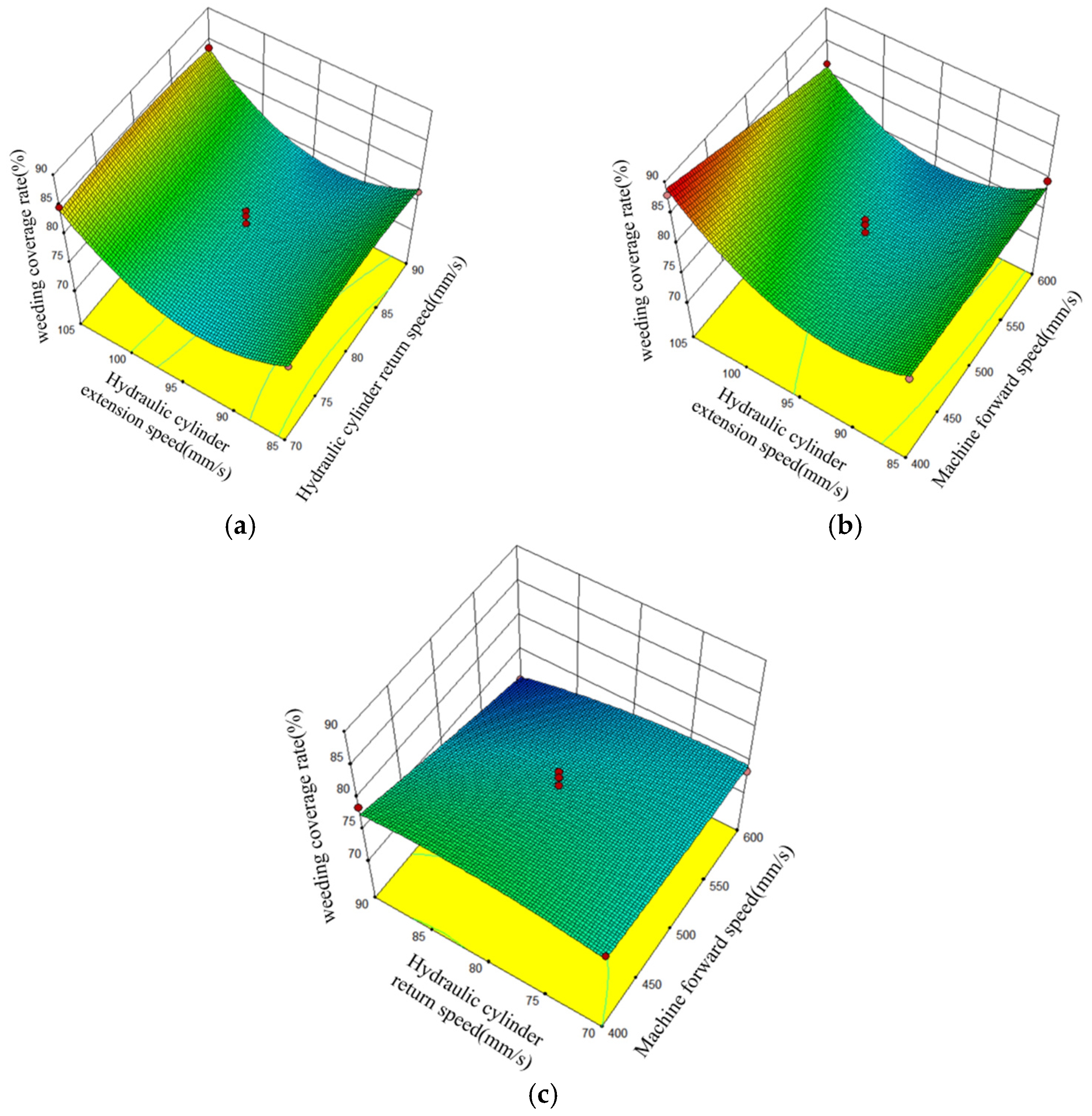
3.2. Field Experiments Results and Analysis

According to the field experiments results, when the hydraulic cylinder return speed exceeds 70 mm/s, the in-row weeding components can normally avoid all grapevines, and the in-row obstacle avoidance system operates stably. Design-Expert 8.0.6 was used to fit the data from the weeding coverage test results in Table 3 and perform a variance analysis (as shown in Table 4) [40,41,42]. The analysis shows that the coefficients for X3 and X32 are significant (p < 0.05), while the other factors are not significant. The p-value for the regression model is less than 0.05, while the p-value for the lack of fit is 0.91, indicating that the regression model is significant and the lack of fit is not significant, confirming the validity of the regression. After removing the insignificant factors, the regression equation for the weeding coverage rate is Y = 75.21 + 3.04X3 + 6.33X32.
The Design-Expert 8.0.6 optimization module was used to optimize the parameters of the regression model. The constraints of the test factors were as follows: the return speed of the hydraulic cylinder was 70–90 mm/s, the forward speed of the machine was 400–600 mm/s, the extension speed of the hydraulic cylinder was 85–105 mm/s, and the evaluation index of the weeding coverage rate took the target maximum value of 100%. The final optimization resulted in a hydraulic cylinder extension speed of 105 mm/s, a machine forward speed of 500 mm/s, a hydraulic cylinder return speed of 80 mm/s, and a weed coverage rate of 84.6%.
According to the regression equation analysis, the extension speed of the hydraulic cylinder is positively correlated with the weeding coverage rate, meaning that the greater the extension speed, the higher the coverage rate of the weeding operation. However, the variance analysis results show that the forward speed of the machine and the hydraulic cylinder return speed do not significantly affect the weeding coverage rate, which contradicts previous research conclusions. This may be due to differences in experimental conditions and potential human errors in the field experiments, leading to some discrepancies between the test results and the simulation results. For example, the machine cannot keep traveling in a straight line all the time. From an overall test performance perspective, this machine effectively meets the normal weeding requirements, with a high weeding coverage rate and stability.
The pattern of the interaction factors regarding weed cover is shown in Figure 24. From Figure 24a, it can be observed that the change in the hydraulic cylinder return speed has little effect on the weeding coverage rate, probably because of the influence of fruit tree branches and leaves in the obstacle avoidance process. With the increase in hydraulic cylinder extension speed, the weeding coverage rate shows an increasing trend. Because the actuating parts indirectly control the weeding shovel, the forward speed of the machine is certain, and the increase in the hydraulic cylinder speed will cause the weeding shovel to return to the operating position more quickly. According to Figure 24b, when the hydraulic cylinder extends, the speed gradually increases and the forward speed of the machine gradually decreases, while the weeding coverage rate tends to increase. Because the forward speed of the machine is certain, an increase in the hydraulic cylinder extension speed will result in the weeding shovel returning to the operating position more quickly. The opposite is also true. The degree of hydraulic cylinder extension speed is certain, and the forward speed of the machine decreases, which will also result in the weeding shovel returning to the operating position more quickly. According to Figure 24c, when the hydraulic cylinder return speed gradually increases and the forward speed of the machine gradually decreases, the weeding coverage rate will show a decreasing trend, but the effect on the weeding coverage rate is not obvious in comparison.
Table 5 shows the comparison between this study and other intra-plant herbicidal machinery studies. As can be seen from the comparison, the working principle of these studies is to destroy the root system of weeds by entering the soil with the weeding tool and moving it laterally, so as to achieve the effect of weeding. However, there are significant differences in obstacle detection methods. Visual detection technology, in practical applications, may be affected by environmental factors, such as weed density and light conditions, which may have a certain impact on the weeding effect. However, the obstacle detection device designed in this study effectively reduces the interference of these environmental factors through the combination of non-contact sensor technology and mechanical tactile technology, thus improving the stability of the weeding system to a certain extent.

4. Discussion

The obstacle detection device on the intra-row weeding machine is crucial for the accuracy of operations. Currently, obstacle detection technologies mainly include machine vision, tactile feedback, and wireless sensor detection. Machine vision is divided into traditional methods and deep learning-based methods. Although the detection accuracy is high, it is greatly affected by environmental factors such as natural light and crop occlusion, and requires large datasets for support, limiting its applicability. Tactile feedback technology is categorized by collision location into working component contact and contact with the touch rod. Since direct contact with the target may cause physical damage to the crops, buffering materials can be installed on the outside of the working components to reduce the contact force, or the parameters of the key components can be evaluated through theoretical calculations. There are many types of wireless sensor detection, such as ultrasonic detection, radar detection, spectral detection, and fluorescence detection. For specific crops, such as grapevines, these sensors cannot detect grapevines through the leaves. Therefore, in practical applications, it is necessary to balance different technologies, considering environmental adaptability, operational safety, time costs, and other factors, in order to choose the optimal obstacle detection solution. In this study, a variety of technical factors were weighed in practical applications, and environmental adaptability, operational safety, and other relevant factors were fully considered to finalize an optimal obstacle detection solution. The solution combines a non-contact sensor with a mechanical haptic structure, effectively overcoming the instability problem that may be encountered when relying solely on non-contact detection, while avoiding the risks that may result from collision obstacle avoidance by the weeding component.
The preliminary analysis from the field experiments shows that the weeding operation coverage is closely related to the extension speed of the hydraulic cylinder, but the forward speed of the machine and the extension speed of the hydraulic cylinder have no significant effect on the weeding coverage rate, which differs from previous research results. Differences in experimental conditions and human errors may have affected the experimental results, which in turn could influence further judgments. The preliminary analysis indicates that the factors affecting the differences in the experimental conditions include the distribution of grapevine roots and leaves, the vine spacing, the tractor output shaft speed, the soil penetration depth, the distance the intra-row weeding device extending into the row, and the curvature of the grapevine trunk. Factors such as the tractor output shaft speed were not kept constant during the experiment, which may have caused fluctuations and deviations in the results. In particular, the distribution of the grapevine roots and leaves may have exerted a significant impact on the experimental results. In the simulation, after the obstacle detection rod first makes contact with the grapevine trunk, the actuation device causes the weeding component to operate. However, in the field experiment, the obstacle detection rod often makes contact with the branches and leaves first. Under the influence of the blocking force, the obstacle rod continues to rotate, and then the actuation device causes the weeding component to operate. In this case, although the obstacle detection and weeding requirements are still met, the starting point for obstacle detection changes significantly, which may substantially affect the weeding coverage rate. Moreover, when the vine spacing is too small, the intra-plant weeding parts just avoid the vines and are ready to reach back to the intra-plant work; they may not reach the designated work position and may have to perform the avoidance operation again. Compared to the experimental conditions in the simulation, changes in the obstacle detection starting point may also affect the weeding coverage rate. These factors may collectively lead to the insignificance of the impact of forward speed and hydraulic cylinder extension speed on the weeding coverage rate. Therefore, it is necessary to further study the specific mechanisms by which these factors affect the weeding coverage rate and optimize the working components or parameters to improve the coverage of weeding operations.

5. Conclusions

(1)
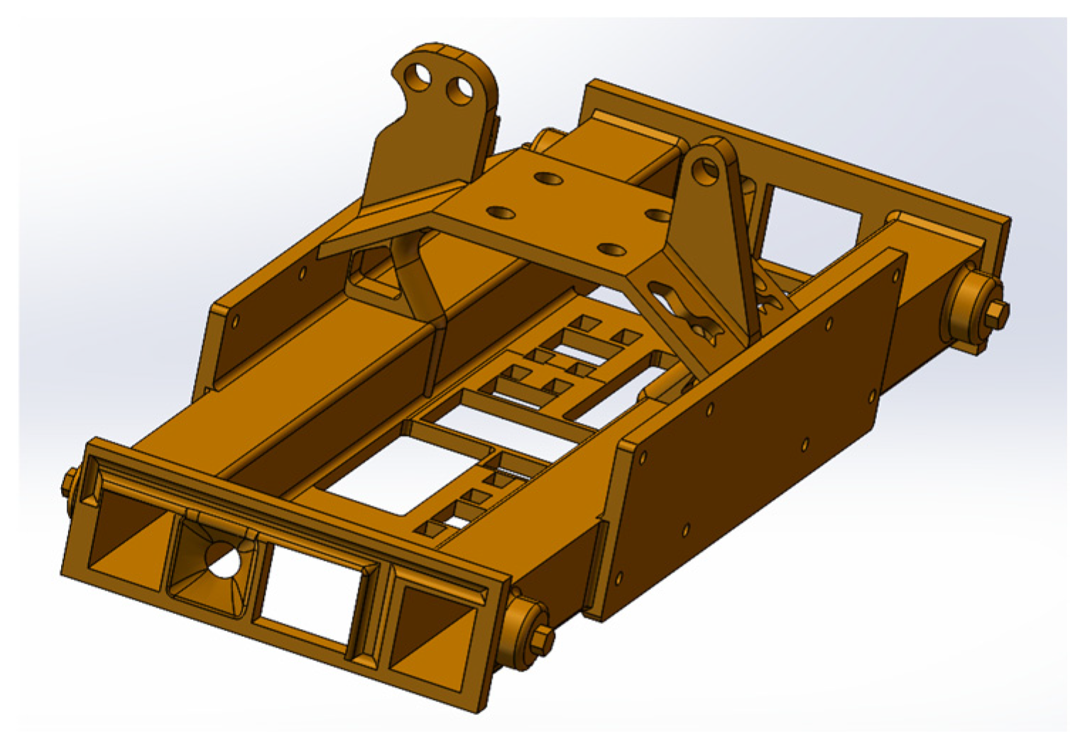
In this study, an orchard intra-plant weeder was designed and theoretically analyzed and calculated. The machine is suitable for orchard environments with sandy soil, with row spacing greater than 3 m and plant spacing greater than 40 cm. The weeding machine integrates sensor technology, row width adjustment devices, depth-limiting devices, inter-row weeding components, and hydraulic systems, providing an intelligent solution for orchard intra-row weeding.
(2)
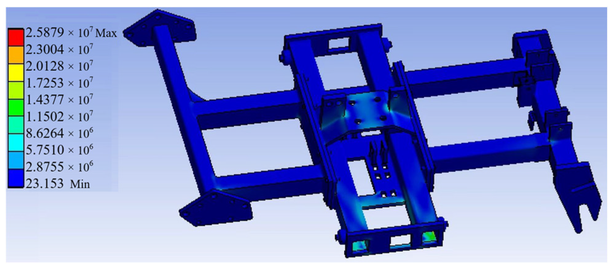
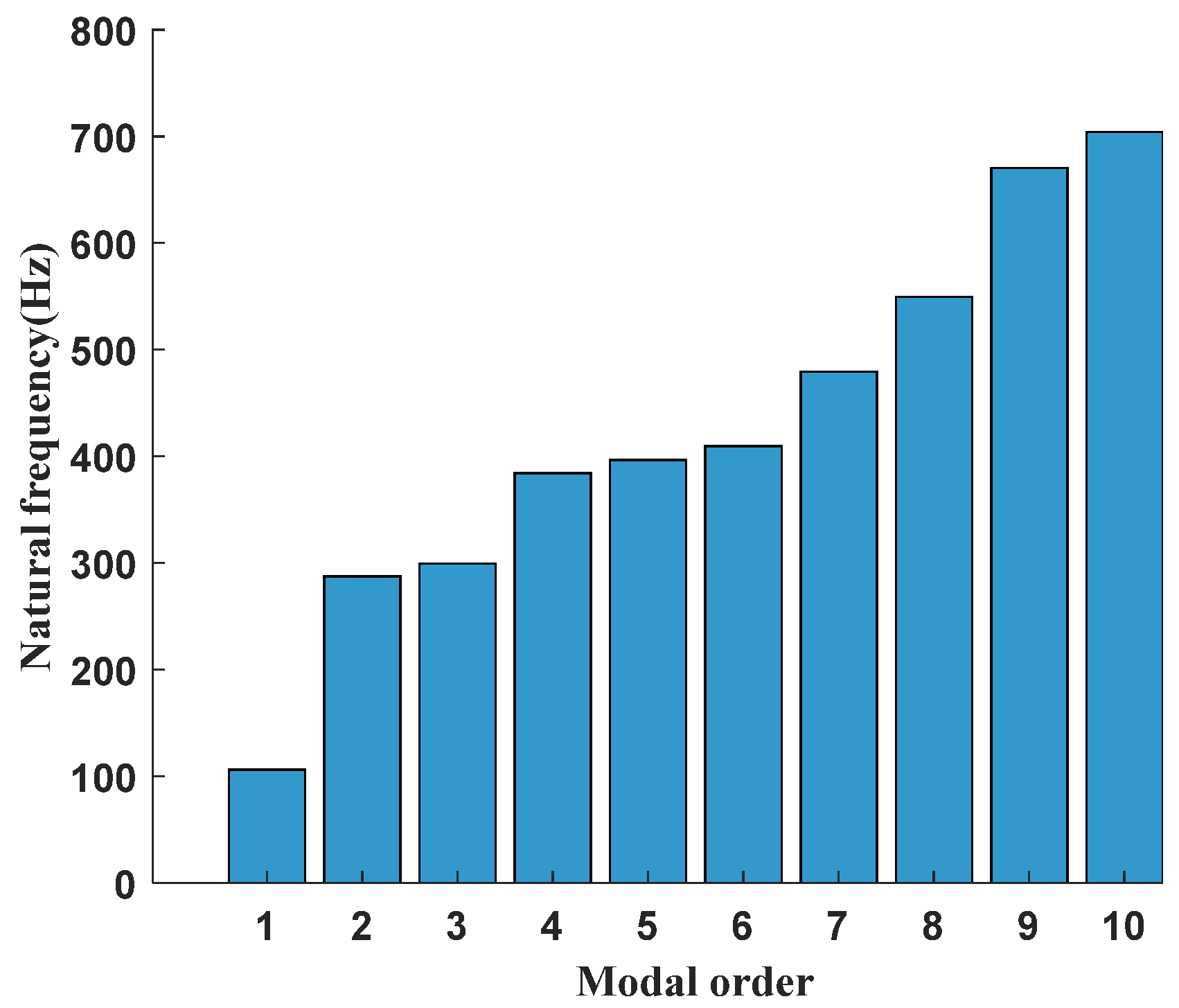
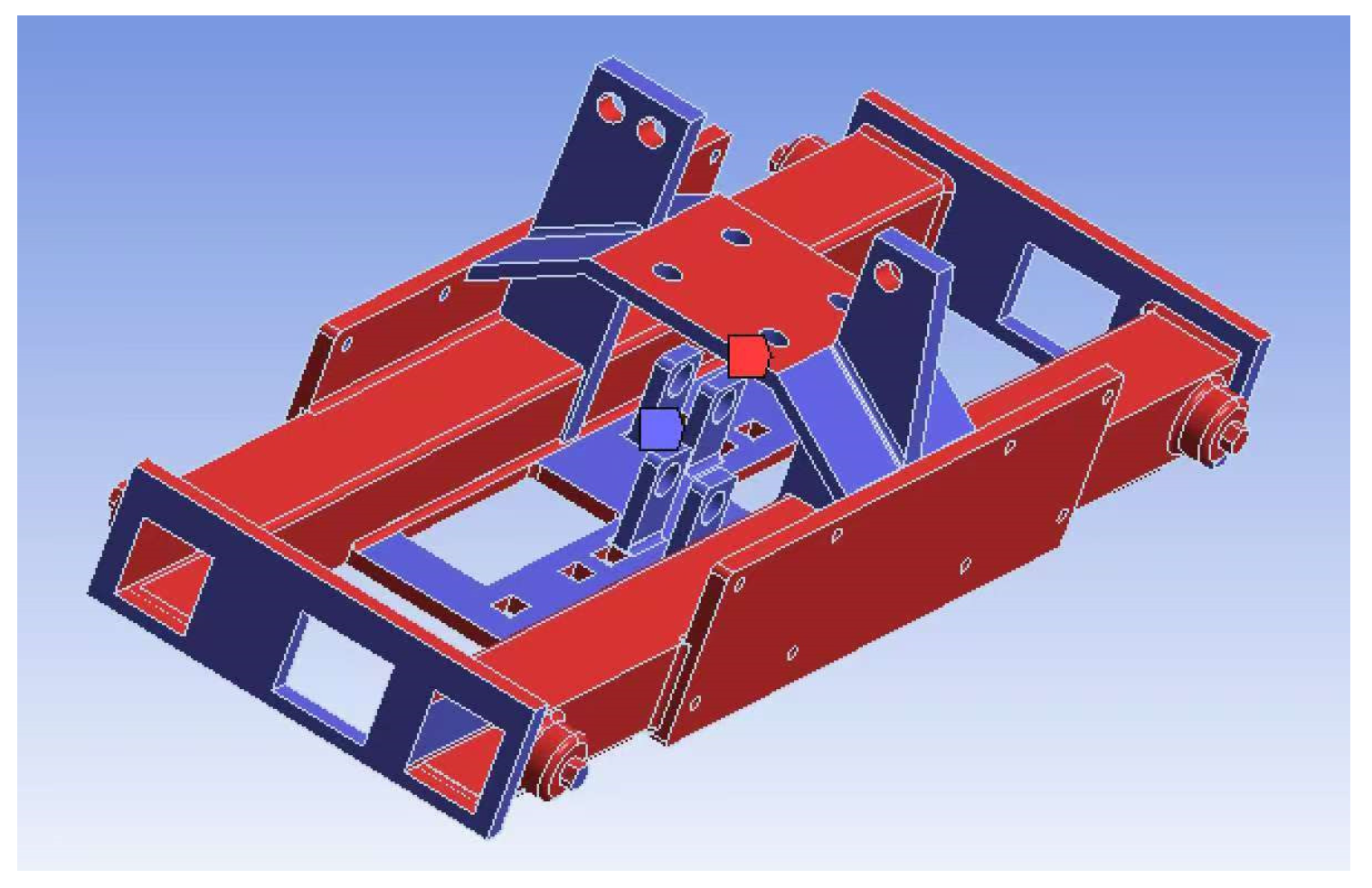
After performing static and modal analyses on the machine chassis of the inter-row weeding machine, the results show that the chassis has good stiffness and safety under static loads. The maximum deformation is 0.068 mm, and the maximum equivalent stress is 25.88 MPa, which is below the designed allowable stress. In the modal analysis, the natural frequency range of the chassis is 106.43 to 703.82 Hz, and the excitation frequencies are not within this range, ensuring that resonance will not occur during actual operations. Furthermore, through topology optimization using the variable density method, the chassis structure was optimized. The optimized bracket weight was reduced by 8%, while meeting the strength and stiffness requirements.
(3)
Based on the field experiments and regression analysis results, the extension speed of the hydraulic cylinder has a significant impact on the weeding coverage rate, while the forward speed of the machine and the return speed of the hydraulic cylinder have no significant effect. Overall, this experiment indicates that the inter-row weeding machine effectively meets the weeding requirements. By selecting optimal parameters, a high weeding coverage rate can be achieved, while also demonstrating excellent obstacle avoidance stability.

6. Future Work

Future research could consider adding another intra-row weeding device on the opposite side of the existing weeding machine to implement a bilateral weeding mode, further improving weeding efficiency. Additionally, we observed slight occasional shaking of the chassis during operation in the experiments. Therefore, improving the chassis or the three-point suspension structure to enhance stability will be the focus of the next phase of work. Finally, the distance adjustment device and the depth-limiting device need to be manually completed by workers, which is not convenient for flexible operations. In the future, we can improve the depth-limit-adjustment device and design an automatic adjusting system based on sensor feedback, which will improve the operating precision, reduce the difficulty of manual adjustment, and also indirectly reduce the frequency of machine failure.

Author Contributions

Conceptualization, W.J., K.T. and X.W.; data curation, K.T.; formal analysis, W.J. and X.D.; funding acquisition, W.J. and M.O.; investigation, K.T.; methodology, K.T. and X.W.; project administration, W.J.; resources, W.J. and X.W.; software, X.W.; supervision, W.J. and M.O.; validation, X.D. and M.O.; visualization, X.W. and X.D.; writing—original draft, W.J., K.T. and X.W.; writing—review and editing, W.J., K.T. and X.W. All authors have read and agreed to the published version of the manuscript.

Funding

This research was supported by the National Key Research and Development Plan of China (grant no. 2023YFD2000503), Project of Faculty of Agricultural Equipment of Jiangsu University (grant no. NZXB20210101), Jiangsu Province and Education Ministry Cosponsored Synergistic Innovation Center of Modern Agricultural Equipment (grant no. XTCX1003), the Open Fund for Key Laboratory of Modern Agricultural Equipment and Technology (Ministry of Education of the People’s Republic of China) (grant no. MAET202113), a project funded by the Priority Academic Program Development of Jiangsu Higher Education Institutions (grant no. PAPD-2023-87), and the Jiangsu University and Wuzhong City Campus Cooperation Project (grant no. zk20230012).

Institutional Review Board Statement

Not applicable.

Data Availability Statement

The data presented in this study are available on request from the corresponding author.

Conflicts of Interest

The authors declare no conflicts of interest.

References

  1. Sebastian, S.; Kalita, K. Theoretical analysis and design of inter cum intra-row wetland paddy field weeder. Crop. Prot. 2024, 181, 106696. [Google Scholar] [CrossRef]
  2. Jiao, J.K.; Hu, L.; Chen, G.L.; Chen, C.W.; Zang, Y. Development and experimentation of intra-row weeding device for organic rice. Agriculture 2024, 14, 146. [Google Scholar] [CrossRef]
  3. Cabrera-Pérez, C.; Llorens, J.; Escolà, A.; Royo-Esnal, A.; Recasens, J. Organic mulches as an alternative for under-vine weed management in Mediterranean irrigated vineyards: Impact on agronomic performance. Eur. J. Agron. 2023, 145, 126798. [Google Scholar] [CrossRef]
  4. Roberts, J.; Florentine, S. A review of the biology, distribution patterns and management of the invasive species Amaranthus palmeri S. Watson (Palmer amaranth): Current and future management challenges. Weed. Res. 2022, 62, 113–122. [Google Scholar] [CrossRef]
  5. Ren, J.; Li, F.D.; Yin, C.B. Orchard grass safeguards sustainable development of fruit industry in China. J. Clean. Prod. 2023, 382, 135291. [Google Scholar] [CrossRef]
  6. Cordill, C.; Grift, T.E. Design and testing of an intra-row mechanical weeding machine for corn. Biosyst. Eng. 2011, 110, 247–252. [Google Scholar] [CrossRef]
  7. Pradel, M.; de Fays, M.; Seguineau, C. Comparative life cycle assessment of intra-row and inter-row weeding practices using autonomous robot systems in French vineyards. Sci. Total. Environ. 2022, 838, 156441. [Google Scholar] [CrossRef]
  8. Palma-Guillén, A.; Salicrú, M.; Nadal, A.; Serrat, X.; Nogués, S. Non-chemical weed management for sustainable rice production in the Ebro Delta. Weed. Res. 2024, 64, 227–236. [Google Scholar] [CrossRef]
  9. Andreasen, C.; Vlassi, E.; Salehan, N. Laser weeding of common weed species. Front. Plant. Sci. 2024, 15, 1375164. [Google Scholar] [CrossRef]
  10. Weisberger, D.; Ray, M.A.; Basinger, N.T.; Thompson, J.J. Chemical, ecological, other? Identifying weed management typologies within industrialized cropping systems in Georgia (US). Agric. Hum. Values 2024, 41, 935–953. [Google Scholar] [CrossRef]
  11. Cabrera-Pérez, C.; Royo-Esnal, A.; Recasens, J. Herbicidal effect of different alternative compounds to control Conyza bonariensis in vineyards. Agronomy 2022, 12, 960. [Google Scholar] [CrossRef]
  12. Fan, Q.Q.; Shen, Y.; Yang, Y.; Zhang, Q.M. A review of remediation strategies for diphenyl ether herbicide contamination. Toxics 2024, 12, 397. [Google Scholar] [CrossRef] [PubMed]
  13. Li, Y.L.; Guo, R.Y.; Liang, X.G.; Yao, B.; Yan, S.W.; Guo, Y.A.; Han, Y.H.; Cui, J.S. Pollution characteristics, ecological and health risks of herbicides in a drinking water source and its inflowing rivers in North China. Environ. Pollut. 2023, 334, 122130. [Google Scholar] [CrossRef]
  14. Mattiello, A.; Novello, N.; Cornu, J.Y.; Babst-Kostecka, A.; Poscic, F. Copper accumulation in five weed species commonly found in the understory vegetation of Mediterranean vineyards. Environ. Pollut. 2023, 329, 121675. [Google Scholar] [CrossRef] [PubMed]
  15. Melander, B.; Lattanzi, B.; Pannacci, E. Intelligent versus non-intelligent mechanical intra-row weed control in transplanted onion and cabbage. Crop. Prot. 2015, 72, 1–8. [Google Scholar] [CrossRef]
  16. Zawada, M.; Legutko, S.; Gościańska-Łowińska, J.; Szymczyk, S.; Nijak, M.; Wojciechowski, J.; Zwierzyński, M. Mechanical Weed Control Systems: Methods and Effectiveness. Sustainability 2023, 15, 15206. [Google Scholar] [CrossRef]
  17. Gagliardi, L.; Fontanelli, M.; Luglio, S.M.; Frasconi, C.; Peruzzi, A.; Raffaelli, M. Evaluation of sustainable strategies for mechanical under-row weed control in the vineyard. Agronomy 2023, 13, 3005. [Google Scholar] [CrossRef]
  18. McCollough, M.R.; Poulsen, F.; Melander, B. Informing the operation of intelligent automated intra-row weeding machines in direct-sown sugar beet (Beta vulgaris L.): Crop effects of hoeing and flaming across early growth stages, tool working distances, and intensities. Crop. Prot. 2024, 177, 106562. [Google Scholar] [CrossRef]
  19. Machleb, J.; Peteinatos, G.G.; Kollenda, B.L.; Andújar, D.; Gerhards, R. Sensor-based mechanical weed control: Present state and prospects. Comput. Electron. Agric. 2020, 176, 105638. [Google Scholar] [CrossRef]
  20. Sozzi, M.; Pasquetti, E.; De Ros, A.; Ferro, F. Performance evaluation of automated implement for vineyard mechanical weed control. In Proceedings of the 20th International Scientific Conference Engineering for Rural Development, Jelgava, Latvia, 26–28 May 2021. [Google Scholar]
  21. Reiser, D.; Sehsah, E.; Bumann, O.; Morhard, J.; Griepentrog, H.W. Development of an autonomous electric robot implement for intra-row weeding in vineyards. Agriculture 2019, 9, 18. [Google Scholar] [CrossRef]
  22. Lei, X.H.; Qi, Y.N.; Zeng, J.; Yuan, Q.C.; Chang, Y.H.; Lyu, X.L. Development of unilateral obstacle-avoiding mower for Y-trellis pear orchard. Int. J. Agric. Biol. Eng. 2022, 15, 71–78. [Google Scholar] [CrossRef]
  23. Jiang, B.; Zhang, J.L.; Su, W.H.; Hu, R. A SPH-YOLOv5x-based automatic system for intra-row weed control in lettuce. Agronomy 2023, 13, 2915. [Google Scholar] [CrossRef]
  24. Assirelli, A.; Liberati, P.; Santangelo, E.; Del Giudice, A.; Civitarese, V.; Pari, L. Evaluation of sensors for poplar cutting detection to be used in intra-row weed control machine. Comput. Electron. Agric. 2015, 115, 161–170. [Google Scholar] [CrossRef]
  25. Mao, J.; Zhao, Z.; Li, X.Y.; Zhao, H.G.; Lin, C.Y. Comprehensive benefit of crop straw return volume under sustainable development management concept in Heilongjiang, China. Sustainability 2023, 15, 4129. [Google Scholar] [CrossRef]
  26. Pan, H.Y.; Zheng, X.Y.; Tian, X.; Geng, Y.; Zhang, X.H.; Xiao, S.J.; Gao, Z.Y.; Yang, Y.X.; Liu, X.C.; Li, L.; et al. Toward sustainable crop production in China: A co-benefits evaluation. J. Clean. Prod. 2022, 361, 132285. [Google Scholar] [CrossRef]
  27. Zhao, S.; Lu, C.; Li, S.; Xu, L.; Ma, S.; Niu, C.; Yan, C.; Tan, H. Optimization and experiment on the performance of kiwi inter-plant mechanical obstacle avoidance weeding machine. Agric. Mech. Res. 2023, 45, 134–142. [Google Scholar]
  28. Xie, K.T.; Zhang, Z.G.; Wang, Y.C.; Tang, J.X.; Yu, X.L. Simulation analysis and test of Panax notoginseng excavating shovel based on LS-DYNA. J. Northeast. Agric. Univ. 2021, 52, 79–88. [Google Scholar]
  29. Liu, W.K.; Li, S.F.; Park, H.S. Eighty years of the finite element method: Birth, evolution, and future. Arch. Comput. Method. Eng. 2022, 29, 4431–4453. [Google Scholar] [CrossRef]
  30. Ji, W.; Qian, Z.J.; Xu, B.; Tang, W.; Li, J.L.; Zhao, D.A. Grasping damage analysis of apple by end-effector in harvesting robot. J. Food. Process. Eng. 2017, 40, 8. [Google Scholar] [CrossRef]
  31. Guan, C.S.; Fu, J.J.; Xu, L.; Jiang, X.Z.; Wang, S.L.; Cui, Z.C. Study on the reduction of soil adhesion and tillage force of bionic cutter teeth in secondary soil crushing. Biosyst. Eng. 2022, 213, 133–147. [Google Scholar] [CrossRef]
  32. Ni, J.H.; Dong, J.T.; Ullah, I.; Mao, H.P. CFD simulation of sucrose flow field in the stem of greenhouse tomato seedling. Int. J. Agric. Biol. Eng. 2022, 15, 111–115. [Google Scholar] [CrossRef]
  33. Zhang, X.Y.; Xu, W.; Li, R.R.; Zhou, J.C.; Luo, Z.Y. Study on sustainable lightweight design of airport waiting chair frame structure based on ANSYS Workbench. Sustainability 2024, 16, 5350. [Google Scholar] [CrossRef]
  34. Guo, M.X.; Fang, M.Z.; Wang, L.Y.; Hu, J.; Qi, J. Performance optimization design study of box-type substations subjected to the combined effects of wind, snow, and seismic loads. Appl. Sci. 2024, 14, 3958. [Google Scholar] [CrossRef]
  35. Yu, C.; Xu, L.; Wang, Q.; Yuan, Q.; Ma, S.; Niu, C.; Yuan, X.; Zeng, J.; Wang, S.; Chen, C. Design and experiment of bilateral operation intra-row auto obstacle avoidance weeder for trellis cultivated grape. Trans. Chin. Soc. Agric. Eng. 2019, 35, 1–9. [Google Scholar]
  36. Naseem, Z.; Iqbal, J.; Zahid, M.; Shaheen, A.; Hussain, S.; Yaseen, W. Use of hydrogen-bonded supramolecular eutectic solvents for eco-friendly extraction of bioactive molecules from Cymbopogon citratus using Box–Behnken design. J. Food. Meas. Charact. 2021, 15, 1487–1498. [Google Scholar] [CrossRef]
  37. Jia, W.D.; Tai, K.L.; Wang, X.W.; Dong, X.; Ou, M.X. Design and simulation of intra-row obstacle avoidance shovel-type weeding machine in orchard. Agriculture 2024, 14, 1124. [Google Scholar] [CrossRef]
  38. Wang, X.Z.; Hong, T.Y.; Fang, W.Q.; Chen, X.Y. Optimized design for vibration reduction in a residual film recovery machine frame based on modal analysis. Agriculture 2024, 14, 543. [Google Scholar] [CrossRef]
  39. Tyflopoulos, E.; Steinert, M. A comparative study of the application of different commercial software for topology optimization. Appl. Sci. 2022, 12, 611. [Google Scholar] [CrossRef]
  40. Najafi, M.; Rahimi, R.; Bräse, S. Synthesis of porphyrin-based MOF/Cloisite-30B nanocomposite for selective dye adsorption: Optimization by Design-Expert, adsorption, and kinetic study. J. Inorg. Organomet. Polym. Materi. 2024, 34, 3817–3830. [Google Scholar] [CrossRef]
  41. Qin, W.C.; Xue, X.Y.; Cui, L.F.; Zhou, Q.Q.; Xu, Z.F.; Chang, F.L. Optimization and test for spraying parameters of cotton defoliant sprayer. Int. J. Agric. Biol. Eng. 2016, 9, 63–72. [Google Scholar]
  42. Huang, J.C.; Tan, L.; Tian, K.P.; Zhang, B.; Ji, A.M.; Liu, H.L.; Shen, C. Formation mechanism for the laying angle of hemp harvester based on ANSYS-ADAMS. Int. J. Agric. Biol. Eng. 2023, 16, 109–115. [Google Scholar] [CrossRef]
  43. Lati, R.N.; Siemens, M.C.; Rachuy, J.S.; Fennimore, S.A. Intrarow weed removal in broccoli and transplanted lettuce with an intelligent cultivator. Weed. Technol. 2016, 30, 655–663. [Google Scholar] [CrossRef]
Figure 1. Technical approach for the design of the intra-row weeding machine.
Agriculture 15 00947 g001
Figure 2. Power flow.
Agriculture 15 00947 g002
Figure 3. Schematic of the internal structure of the sensor system.
Agriculture 15 00947 g003
Figure 4. Two-dimensional top view of the sensor system. 1. Rebound shaft; 2. Bump; 3. Hook spring; 4. Tension adjustment device; 5. Photoelectric sensor; 6. Clamping device; 7. Touch rod; 8. Fruit tree. θ1 (°) is the angle between lines CD and AD, representing the rotation angle of the touch rod after encountering an obstacle. l1 (mm) is the distance from point A to point B. l2 (mm) is the distance from point A to point C, representing the spring length after the rotation of the rebound shaft. l3 (mm) is the distance from point E to point G, representing the length from the collision contact point to the rebound shaft. l4 (mm) is the distance from point D to point H, perpendicular to AH. l5 (mm) is the distance from point A to point I, representing the spring’s natural length. l6 (mm) is the distance from point I to point B, representing the spring’s increment in length. R (mm) is the distance from point B to point D, also represented as the distance from point B to point D. F (N) is the contact force.
Agriculture 15 00947 g004
Figure 5. Mechanism design of the intra-row weeding machine.
Agriculture 15 00947 g005
Figure 6. Schematic of the weeding device. 1. Chassis; 2. Three-point hitch; 3. Distance adjustment device; 4. Clamping device; 5. Connection frame; 6. Sensor device; 7. Double-acting hydraulic cylinder; 8. Rocker mechanism; 9. Weeding shovel. θ2 (°) is the angle between lines LN and NO. θ3 (°) is the angle between lines LJ and LN. l7 (mm) is the distance from point J to point K. l8 (mm) is the distance from point K to point L. l9 (mm) is the distance from point J to point M, representing the length of the hydraulic cylinder and its push rod. l10 (mm) is the distance from point L to point M. l11 (mm) is the distance from point L to point N. l12 (mm) is the distance from point N to point O. l13 (mm) is the working width of the weeding shovel.
Agriculture 15 00947 g006
Figure 7. Hydraulic system.
Agriculture 15 00947 g007
Figure 8. Top view of the intra-row weeding device. 1. Tractor output shaft; 2. Gear pump; 3. Overflow valve; 4. Oil tank; 5. Two-position four-way electromagnetic directional valve; 6. Check valve; 7. Throttle valve; 8. Double-acting hydraulic cylinder; 9. Weeding shovel. F1 (N) is the thrust of the hydraulic cylinder’s push rod. Fx (N) is the resultant resistance force in the X direction from the soil acting on the weeding shovel. θ5 (°) is the angle between lines JM and LM. θ4 (°) is the angle between lines LK and LM. l14 (mm) is the minimum distance from the line in the Fx direction to the hinge point L. l15 (mm) is the distance from point L to point P; point P is in the FX direction and is also the bisecting point of the length of the weeding shovel.
Agriculture 15 00947 g008
Figure 9. Chassis of the intra-row weeding machine.
Agriculture 15 00947 g009
Figure 10. Mesh model of the intra-row weeding machine.
Agriculture 15 00947 g010
Figure 11. Load distribution of the intra-row weeding machine. 1. The self-weight load of the in-field weeding components on the chassis; 2. The soil resistance load; 3. Earth’s gravity; 4. The self-weight load of the fuel tank and other related components at the top of the chassis.
Agriculture 15 00947 g011
Figure 12. Weeding equipment in working condition.
Agriculture 15 00947 g012
Figure 13. Tractor-rear-mounted weeding equipment.
Agriculture 15 00947 g013
Figure 14. Operation of the intra-row weeding machine.
Agriculture 15 00947 g014
Figure 15. Displacement contour map.
Agriculture 15 00947 g015
Figure 16. Equivalent stress contour map.
Agriculture 15 00947 g016
Figure 17. First six modal shapes of the total deformation simulation contour map.
Agriculture 15 00947 g017
Figure 18. Natural frequencies of the first ten modal shapes of the chassis.
Agriculture 15 00947 g018
Figure 19. Retained chassis and its optimized area.
Agriculture 15 00947 g019
Figure 20. Reconstructed model.
Agriculture 15 00947 g020
Figure 21. Displacement contour map after topology.
Agriculture 15 00947 g021
Figure 22. Equivalent stress contour map after topology.
Agriculture 15 00947 g022
Figure 23. Natural frequencies of the first ten modes of the optimized chassis.
Agriculture 15 00947 g023
Figure 24. Effects of interaction factors on weeding coverage rate. (a) Influence of hydraulic cylinder extension and retraction speeds on weeding coverage rate; (b) the effect of hydraulic cylinder extension speed and machine forward speed on weeding coverage rate; (c) the effect of hydraulic cylinder retraction speed and machine forward speed on weeding coverage rate.
Agriculture 15 00947 g024
Table 1. Field experiment plan.
LevelsFactors
Hydraulic Cylinder Return Speed (mm/s)Machine Forward Speed (mm/s)Hydraulic Cylinder Extension Speed (mm/s)
−17040085
08050095
190600105
Table 2. Natural frequency before and after chassis optimization.
Modal OrderNatural Frequency Before Optimization/HzNatural Frequency After Optimization/Hz
1109106.43
2280.54287.46
3290.82299.5
4366.7384.34
5391.32396.62
6400.15409.63
7477.8479.53
8536.99549.55
9547.09670.15
10673.49703.82
Table 3. Results of the field experiments.
Test NumberFactorsWeeding Operation Coverage Rate
(%)
Machine Forward Speed
X1 (mm/s)
Hydraulic Cylinder Return Speed
X2 (mm/s)
Hydraulic Cylinder Extension Speed
X3 (mm/s)
1−1−1076.5
21−1073.4
3−11078.7
411070.3
5−10−179.0
610−179.8
7−10188.0
810181.7
90−1−178.5
1001−176.7
110−1184.8
1201183.8
1300070.3
1400074.4
1500076.6
1600078.8
1700077.9
Table 4. Regression model significance test results.
SourceSum of SquaresdfMean SquareF Valuep Value
Model305.41933.934.590.0286
X136.13136.134.880.0628
X21.7111.710.230.6452
X373.81173.819.980.0160
X1 × X27.0217.020.950.3624
X1 × X312.60112.601.700.2331
X2 × X30.1610.160.0220.8872
X120.09510.0950.0130.9131
X224.4214.420.600.4647
X32171.121171.1223.130.0019
Residual51.7977.40
Lack of Fit5.7331.910.170.9141
Pure Error46.06411.52
Cor Total357.2016
Table 5. Comparison of related studies.
This StudyRef [23]Ref [43]
Driving method for weeding partsHydraulic drivePneumatically drivenHydraulic drive
Applicable sceneFruit treesLow-growing vegetables and bright scenesLow-growing vegetables and bright scenes
Obstacle detection methodsCombined approach of non-contact sensors and mechanical haptic structuresMachine vision inspectionMachine vision inspection
Weeding toolsWeeding shovelTwo weeding bladesTwo weeding poles per unit
Disclaimer/Publisher’s Note: The statements, opinions and data contained in all publications are solely those of the individual author(s) and contributor(s) and not of MDPI and/or the editor(s). MDPI and/or the editor(s) disclaim responsibility for any injury to people or property resulting from any ideas, methods, instructions or products referred to in the content.

