Article

Design and Test of an Energy-Saving Bionic-Inspired Rotary Blade: A Study on Power Consumption and Soil Surface Quality

1
College of Engineering, Northeast Agricultural University, Harbin 150030, China
2
Key Laboratory of High Efficient Seeding and Harvesting Equipment, Ministry of Agriculture and Rural Affairs, Northeast Agriculture University, Harbin 150030, China
*
Author to whom correspondence should be addressed.
These authors contributed equally to this work.
Agriculture 2025, 15(9), 938; https://doi.org/10.3390/agriculture15090938
Submission received: 25 March 2025 / Revised: 16 April 2025 / Accepted: 23 April 2025 / Published: 25 April 2025
(This article belongs to the Section Agricultural Technology)

Abstract

:
To reduce the power consumption of rotary tillage and enhance the operational quality of rotary tillage, a rotary blade that imitates the surface of a pufferfish was designed through reverse engineering. The bump structure on the pufferfish surface was employed to decrease the power consumption when the blades till the soil. The performance of the bionic blade was investigated. A single-factor soil bin test was conducted, with the forward speed of the rotary tiller and the rotation speed of the blade shaft serving as the test factors, and the power consumption of the rotary tiller and the ground surface flatness as the evaluation indexes. The test results revealed that the power consumption of the rotary tiller initially decreases, then increases, and finally decreases with the increase in the forward speed of the rotary tiller. It is positively correlated with the rotation speed of the blade shaft. The ground surface flatness is positively correlated with the forward speed of the rotary tiller but negatively correlated with the rotation speed of the blade shaft. Compared with the rotary tiller with standard IT225 blades, the rotary tiller with bionic blades achieves a 9.4% reduction in power consumption and a 6.5% improvement in ground surface flatness. This study has demonstrated that the bump structure of the pufferfish surface can effectively reduce the power consumption of the blades and enhance ground surface quality, thus offering novel insights for the development of energy-saving tillage tools.

1. Introduction

Rotary tilling, as one of the commonly employed soil cultivation methods [1], could effectively break soil clods, reduce soil compaction, loosen soil structure, and enhance soil porosity. Rotary tillage operation is mainly applied to soil treatment in farmland before sowing, land leveling, straw return, and other operations, efficiently crushing the soil to create better conditions for planting. As the key component of the rotary tiller, the rotary blade is rotated by the blade roller, which is powered by the traction device. While the rotary tiller advances forward, the soil is cut into fragments and thrown backward by the rotary blade. The ejected soil collides with the protective housing and drag board, undergoing further breakage before falling back onto the ground. During operation, the contact between the rotary blade and the soil generates resistance, which constitutes the main source of the power consumption of the rotary tiller [2]. During rotary tillage, the resistance between the blade and the soil, soil adhesion, resistance to rotation and forward movement of rotary tiller [3], and the power consumption of the transmission will increase the power consumption of the rotary tillage [4], which will further lead to an increase in fuel consumption and a decrease in the income of farmers. During rotary tillage, the edge of the rotary blade plays a crucial role in cutting soil. The resistance of the blade cutting the soil will be affected by the interaction between the blade surface and the soil. To enhance the performance of blades cutting the soil, many experts and scholars have studied the blade edge curves and the blade surface. The blade mirroring the earthworm-like body surface, inspired by the mucus and link structure of earthworms, could reduce the tillage resistance by 12–18%. It also could reduce the adhesion of the soil and enhance the uniformity of soil crushing in the viscous soil, but its bionic coating has poor abrasion resistance and requires frequent maintenance. Moreover, the effectiveness of the bionic structure could diminish during high-speed operation [5]. The bionic blade, inspired by the microgroove structure of sharkskin, could reduce straw tangling by over 30% on straw-covered surfaces and decrease power consumption by approximately 15%. However, the processing cost of its microgroove structure was high, and it was susceptible to abrasion from hard impurities [6]. The imitation mole paw multi-layer crushing rotary blade was based on the front paw grading crushing structure of a mole as a bionic prototype, and it was mainly utilized in hard soil and slate, and it could increase the efficiency of crushing the soil by 20%. It could also enhance the stability of rotary tilling and increase the impact resistance of the blade edge. However, it had a complex structure, high manufacturing cost, and could cause an increase in power consumption due to excessive crushing in sandy soils [7]. The imitation pangolin scale wear-resistant blade was designed based on the stacked-tile arrangement and high hardness of pangolin scales. It could effectively deflect the impacts of gravel in stony or gravelly soils through its surface scale structure, thereby prolonging the lifespan of the blade by 40% to 50%. However, the stacked-tile design could increase the weight of the blade, which may affect its dynamic balance [8]. The bionic blade was designed based on the contour curve of the upper jaw of the flying locust, extracting the irregular raised structure of its left and right teeth. It could effectively reduce resistance of cutting rice straw and the soil, and the power consumption of the device could be reduced by 5.48%. However, the dimension of the bionic bump must be strictly matched with the prototype. If the dimensions were too large, the drag reduction effect would decrease, and drag could even increase due to disturbances in the boundary layer or soil buildup [9]. Although the current research on rotary tillage blades can meet the general field operation requirements, it is necessary to carry out in-depth research on the interaction between rotary tillage blades and soil mechanical properties. These studies can provide a solid foundation for the design and utilization of rotary tillage blades. The structure and shape of the blade have a direct impact on the soil quality and power consumption of the rotary tiller. Existing research primarily focuses on optimizing and improving the blade curve and surface. The resistance of cutting the soil can be reduced by optimizing the blade curve, and the cutting performance of the blade can be enhanced. The optimization of the blade surface can reduce the friction resistance between the blade and the soil, reduce soil adhesion, and improve soil fragmentation. Some scholars also apply the bionic principle in blade design, such as the imitation rabbit paw toe structure rotary blade [10] and the imitation mole paw toe rotary blade [11]. Soil animals are mostly selected as bionic objects, based on their contact characteristics with the soil, which can mainly improve the drag reduction effect of the blade. In this study, we consider selecting marine organisms as bionic prototypes, utilizing their self-cleaning properties to design rotary tillage blades to reduce the adhesion of the soil to the blades [12]. The blade can shake off soil through its surface properties and centrifugal force during rotation. This design can also reduce frictional resistance and minimize soil accumulation, which is feasible to a certain extent.
The pufferfish non-smooth surface is characterized by bump structures formed through its subcutaneous spines. These bump structures on its body surface achieve drag reduction and self-cleaning effects [13]. Through reducing the contact area with the external environment and altering the flow characteristics of the boundary layer, these bump structures effectively decrease frictional resistance between water flow and the body surface while inhibiting contaminant adhesion, thereby maintaining surface cleanliness [14]. During cutting soil, the continuous cutting and throwing of soil through the rotary blade generate frictional power consumption. Therefore, it is feasible to apply the bump structural design inspired by pufferfish to optimize the structure of rotary blades [15].
This study selected the pufferfish as the bionic prototype, analyzing its bump structure and applying these features to the surface of a standard IT225 rotary blade to design a bionic rotary blade. Through soil bin tests, the cutting soil performance and power consumption of the bionic rotary blade were investigated, while its superiority was demonstrated through comparative analysis with a standard IT225 rotary blade. The specific objectives of this study are the following: (1) Based on the reducing resistance characteristics of the pufferfish surface bump structure, the bionic drag reduction units were extracted through employing reverse engineering technology and arranged on the blade surface to design a bionic rotary blade. (2) The forward speed of the rotary tiller and rotation speed of the blade shaft were set as test parameters to conduct soil bin tests. We investigated the influences of key parameters on the power consumption of the rotary tiller and ground surface flatness. Through comparative analysis with a standard IT225 rotary blade, the performance of the bionic rotary blade was validated. This study could provide reference for the optimal design of a rotary blade structure and provide new thought for the study and development of energy-saving tillage blades.

2. Materials and Methods

2.1. Materials

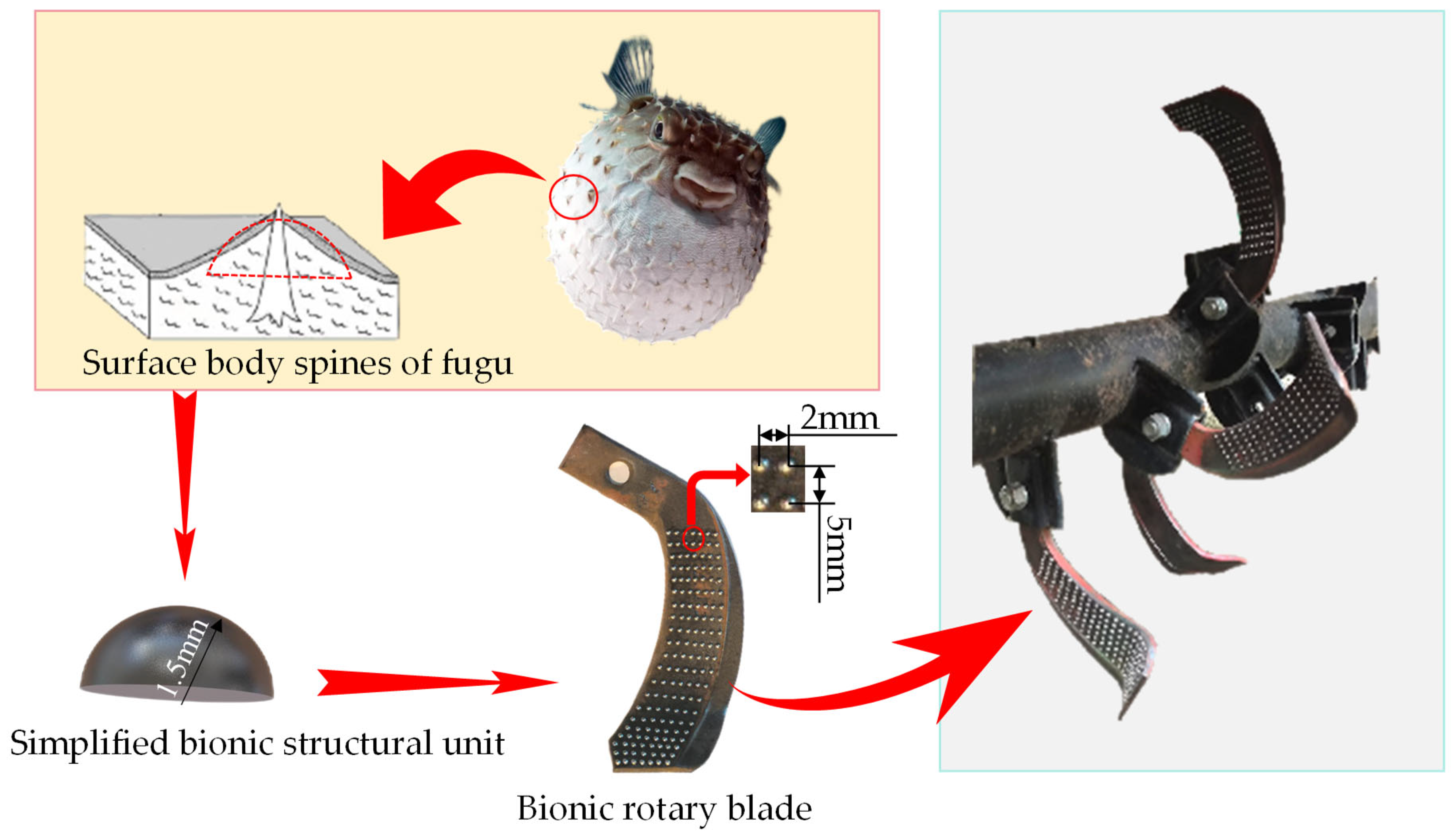
2.1.1. Design of Bionic Pufferfish Rotary Blade

The bump structures formed by the subcutaneous spines on the pufferfish’s body surface have been demonstrated in existing studies to exhibit excellent drag reduction and self-cleaning properties [16]. The densely arranged bump structures reduced the contact area between the blade and soil surface, minimized dirt adhesion and friction-induced energy consumption, and effectively lowered motion resistance. The subcutaneous spines of the pufferfish have a height of approximately 800–1500 μm and a base width of 200–400 μm, with a height-to-width ratio of 3.75–4 mm [17], approximating the bump structure. Existing studies have shown that simplifying this structure into hemispherical bumps achieves superior drag reduction effects. Furthermore, rationally arranging hemispherical bionic structures on the surface of agricultural machinery based on practical conditions further enhances drag reduction performance [18]. Compared to standard soil-dwelling organisms (e.g., pangolins, earthworms), the pufferfish’s body surface exhibits stronger self-cleaning characteristics, attributed to the reduced contact area between the bump structure and the external environment, thereby lowering the likelihood of contaminant and microbial adhesion. Therefore, the pufferfish was selected as the bionic prototype. Based on its hemispherical bump structure, standard IT225 rotary blade surfaces were optimized. Through pre-tests using the Discrete Element Method (DEM), the performance of the bionic blade was compared with that of standard IT225 rotary blades. It was found that oversized bionic bump units increased soil-cutting resistance on the blade surface. Consequently, the height range of the bionic bump units was determined to be 0.5–2 mm. The size of the bionic unit was determined by a one-factor test of the simulation conducted in a follow-up article. Given that soil clod particle sizes typically range from 0.25 to 10 mm [19], the horizontal and vertical spacing between adjacent bionic bump units were set to 2 mm and 5 mm, respectively, ensuring that the spacing was smaller than most soil clod dimensions. Selecting low-damping materials such as polyurethane and Teflon for processing bionic bump units could potentially offer better resistance reduction. However, considering the connection strength between the material and the steel, the processing cost, and the reliability of blade use, the final selection was 420-type stainless steel. This material offers a superior balance of strength, corrosion resistance, and cost-effectiveness, making it suitable for the bionic bump units. A total of 150 bionic bump units were distributed on the blade surface. The remaining structural parameters of the bionic rotary blade matched those of the standard IT225 rotary tiller, as detailed in Table 1 [20]. The 3D model and physical prototype of the bionic rotary blade are shown in Figure 1.

2.1.2. Testing Equipment

The test was conducted in the soil bin at Northeast Agricultural University, which measured 80 m in length, 3 m in width, and had a soil depth of 1.5 m. A rotary tiller model 1GKN-160 was used for the test, with its specific parameters listed in Table 2. The tiller was equipped with IT225 standard rotary blades, with 18 blades symmetrically installed on both the left and right sides. The traction device is TTC series electric frequency conversion four-wheel drive earth tanker, with maximum traction force of 1.5 t, maximum traveling speed of 10 km·h−1, power output shaft speed of 200–1100 r∙min−1, supporting power of 80 kW. The system of testing is shown in Figure 2. The rotary tiller operated in forward rotation mode.

2.2. Methods

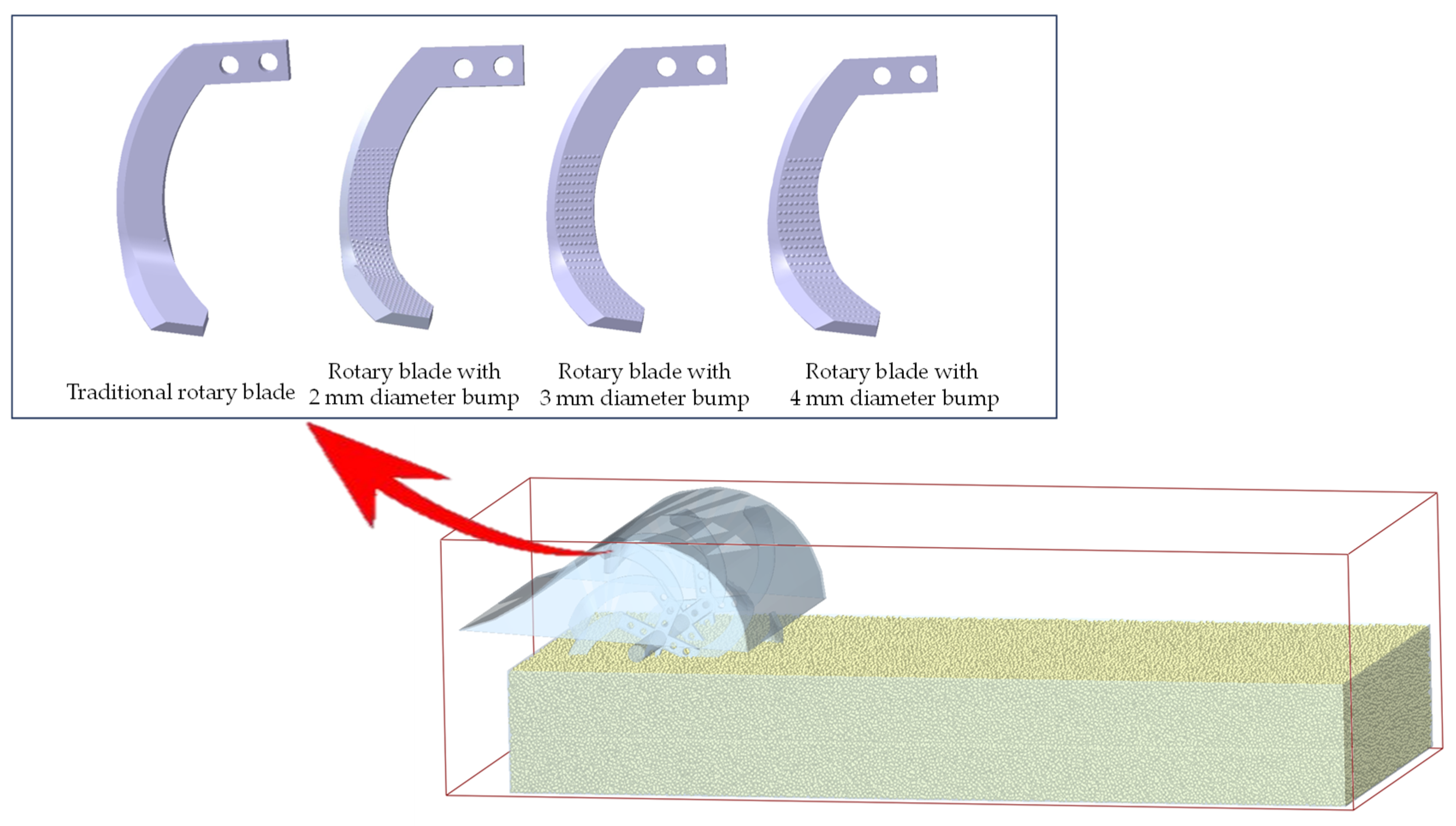
2.2.1. DEM Simulation

The discrete element simulation required the setting of interaction parameters between soil particles and between soil and contact materials. The primary simulation parameters utilized in the test are detailed in Table 3 [21]. The soil parameters were configured based on typical cohesive soils found in northeastern China, following the Hertz–Mindlin (no slip) model implemented in EDEM. A soil bin model with dimensions of 1800 mm (length) × 800 mm (width) × 140 mm (height) was constructed. The simulated tillage duration was set to 2 s, employing the Rayleigh time step of 1 × 10⁻⁸ s and an actual time step of 2 × 10⁻⁹ s. The soil particle size played a crucial role in determining both simulation accuracy and computational time. Excessively small particle sizes led to prolonged computational durations, while overly large particles compromised the authenticity of the simulation. To strike a balance between computational efficiency and accuracy, the soil particle radius was set to a range of 1–3 mm, ensuring simulation performance without significant distortion. According to rotary tiller standards, the forward speed range for subsequent soil bin tests was defined as 1–5 km∙h−1, and the rotation speed of the blade shaft was defined as 150–350 r∙min−1. Intermediate values were chosen for the simulation: a forward speed of 3 km∙h−1 and a blade shaft rotational speed of 250 r∙min−1. The simulation encompassed the rotary blades with bionic bump unit diameters of 2 mm, 3 mm, and 4 mm, along with a traditional smooth-surface blade, as depicted in Figure 3.

2.2.2. Preparation for Soil Bin Test

The soil bin test was carried out in Northeast Agricultural University (126.726° E, 45.743° N) of HeiLongjiang Province, in the northeast of China. Prior to the test, five random sampling points were selected in the soil bin. An SC990 compaction meter (Laing Technology Manufacturing Engineering, Weifang, China) was used to measure soil compaction at depths of 2.5 cm, 5.0 cm, 7.5 cm, 10.0 cm, 12.5 cm, and 15.0 cm below the surface. The average soil compaction values were determined as 54.75 kPa, 109.75 kPa, 171.75 kPa, 148.75 kPa, 130.50 kPa, with an overall average compaction of 123.10 kPa. According to national standards, the absolute moisture content of soil for rotary tiller operation was specified to be 15–25%. A predetermined amount of water was added before the test to achieve the target moisture content. The soil samples were collected from the soil bin, and the bulk density and soil moisture content were monitored as 1.30 g·cm−3 and 16.31%, respectively. The soil shear modulus measured with a triaxial testing system was 1 × 10⁸ Pa. The particle distribution of the soil sample obtained from the experimental area was measured via a GZS-1 high-frequency vibrator (Qingda Test Instrument Manufacturing Co., Ltd., Tianjin, China) and a laser particle size analyzer (BT-9300 H, OmecInstrument Co., Ltd., Zhuhai, China) after the soil sample was milled and sifted. According to the international standard of soil texture classification, the soil type in the experimental area was loam and included 25.7% of clay, 49.6% of silt, and 24.7% of sand. This soil ratio is consistent with standard northeastern black soil.

2.2.3. Test Design

A single-factor test was designed with forward speed of the rotary tiller and rotation speed of the blade shaft as test factors, and the power consumption of rotary tillage and ground surface flatness as evaluation indexes [22,23]. The number of experimental replicates for each test group was three and the final experiment results were averaged.
(1)
Test factors
According to the GB/T5668-2017 [20] national standard for rotary tillers, the forward speed of the rotary tiller and the rotation speed of the blade shaft were selected as test factors. The forward speed range of the tested rotary tiller was set to 1–5 km·h−1 [20], and the cutter shaft rotational speed was set to 150–350 r·min−1 [20]. The speed ratio between the power take-off shaft and the blade shaft was fixed at 1:1. Based on these parameters, the factor-level table for the test was designed, as shown in Table 4.
(2)
Evaluation indexes
Prior to the test, we employed the three-point hitch lever to control the lifting and lowering of the rotary tiller, ensuring consistent tillage depth of the rotary blade. During the test, a 5 m distance was reserved at both the front and rear of the test area as acceleration and deceleration zones for the soil bin vehicle. The torque measurement system was an integral component of the tractor truck. Strain gauges were employed to capture the torque signal from the power output shaft of the tractor truck. This torque signal then underwent a series of processing steps, including filtering, noise reduction, and amplification. Subsequently, the processed data were transmitted wirelessly to the computer onboard the tractor truck, enabling real-time output and accurate recording of torque values. The torque variation of the power take-off shaft over time was output and recorded by a computer. The power consumption of rotary tillage was expressed by Formula (1) [24].
y = T n 9550 × 100 %
where y represents power consumption of rotary tillage (kW), T represents the torque of the power output shaft, which can be output by the tractor truck (N∙m), n represents the rotational speed of the power output shaft (r∙min−1), and the desired value in the experiment can be set through the tractor truck; the 9550 in Equation (1) is the coefficient for calculating the power consumption.
To measure the ground soil flatness, the soil surface was first leveled. A weight object was used to ensure that the soil surface profiler was positioned perpendicular to the ground, while a level was employed to guarantee that the profiler was placed horizontally. The plane defined by the lowest point of the soil surface curve, as captured by the profiler, was established as the datum plane. The surface flatness was then calculated based on the vertical distances from each point on the soil surface curve to this datum plane. Additionally, a solid black background plate was set up to facilitate subsequent image processing. The detailed method is shown in Figure 4.
During the image processing phase, we first standardized the color of the red region corresponding to the soil surface profiler. Subsequently, we applied a mask to distinguish between the red and non-red areas. By extracting the boundary line between these areas, we identified the lowest point on this boundary line, which was used to define the reference plane. The ground surface flatness was then calculated utilizing MATLAB software (2023b) based on this reference plane. The vertical distance from this baseline to the soil surface at each measurement point was recorded as di. The average vertical distance d and standard deviation Sd of all measurement points were calculated. Each group of experiments was repeated five times, and the average standard deviation Sd was used to represent ground surface flatness. A smaller Sd indicated higher ground surface flatness and better tillage quality. Based on the acquired data, the ground surface flatness was expressed by Formulas (2) and (3). After each tillage operation, five equidistant points were selected on the tilled soil surface for calculation.
d = i = 1 n d i n
S d = i = 1 n ( d i d ) 2 n 1
where Sd represents the ground surface flatness (mm), di represents the vertical distance from each part of the ground to the standard surface (mm), d represents the average value of the distance from all measurement points to the standard surface (mm).

2.3. Data Analysis

The two-way analysis of variance (ANOVA) was performed by using statistical software (Origin 2021). The significance of the effects of different test factors on each index were analyzed under the confidence coefficient of 95%.

3. Results and Discussion

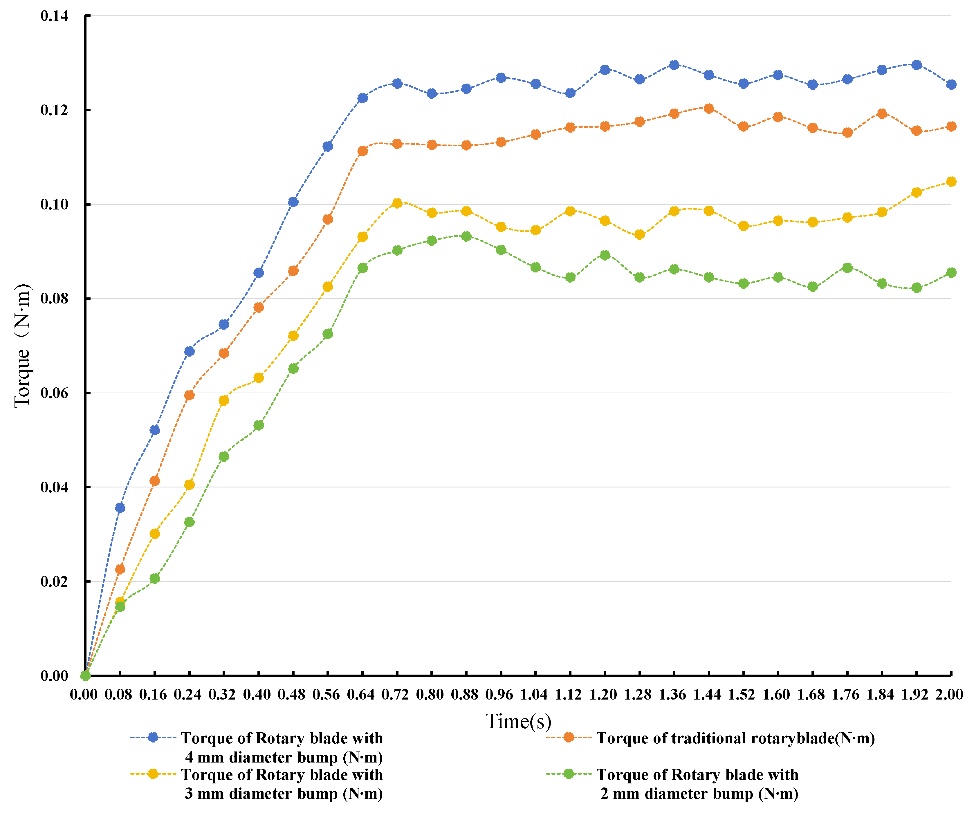
3.1. Bionic Bump Unit Size Determination

The simulation results of rotary blades with bionic bump units of different sizes are shown in Figure 5. The rotary blade with 2 mm diameter bionic bump units exhibited the lowest torque. In contrast, the torque of the blade with 3 mm bionic bump units was slightly higher than that of the 2 mm units. As the diameter of the bionic bump units increased further, the torque continued to increase but remained lower than that of the traditional rotary blade. When the diameter of the bionic bump unit reached 4 mm, the torque of the bionic blade exceeded that of the traditional rotary blade. Therefore, the bionic blade with the 2 mm bionic bump units exhibited the best drag reduction effect. The torque of the blade with 3 mm bionic bump units was only higher by 0.01 N∙m than that of the blade with 2 mm bionic bump units. However, considering the challenges associated with achieving such precise dimensions using the current manufacturing technique and the potential for processing errors, the 3 mm bionic bump units were deemed a more practical choice.

3.2. Effect of Test Factors on Power Consumption

3.2.1. Effect of Forward Speed of Rotary Tiller on Power Consumption

The effect of the forward speed of the rotary tiller on power consumption under different blade types is shown in Figure 6. From the ANOVA results, it could be seen that the blade type and forward speed of the rotary tiller had a significant effect on power consumption (p less than or equal to 0.05). Both the bionic rotary blades and standard IT225 rotary blades exhibited a trend in power consumption that initially decreased, then increased, and finally decreased again as the forward speed of the rotary tiller increased. When the forward speed was 1 km∙h−1, the cutting pitch of the rotary tillage blade was excessively small, causing the knife to re-till soil that had already been processed, which resulted in a significant increase in tillage resistance.
The effect of the forward speed of the rotary tiller on the power consumption of the rotary tiller under different blade types was shown in Figure 6. The results show that p less than or equal to 0.05 indicates that the blade type had a significant effect on the power consumption of the rotary tiller. When the forward speed of the rotary tiller increased from 1 km∙h−1 to 2 km∙h−1, although the cutting pitch increased, the phenomenon of soil re-tillage was weakened, which reduced the torque of the blade shaft, and the power consumption of the rotary tillers would be reduced. This was similar to the results of Yang Yuwan’s study [25]. When the forward speed increased from 3 km∙h−1 to 5 km∙h−1, the cutting pitch continued to increase, but the further increase in speed led to the soil being thrown rapidly. The soil and the blade were not in full contact with each other, and the resistance between the blade and the soil would be reduced, resulting in a significant reduction in power consumption. When the rotation speed of the blade shaft was 250 r∙min−1 and the forward speed of the rotary tiller was 3 km∙h−1, the power consumption of rotary tillage was the highest, and the power consumption for the bionic and standard blade rotary tillers was 15.92 kW and 16.23 kW, respectively. At this time, the rotary tiller with bionic blades had a lower power consumption of 0.69 kW compared to that of the rotary tiller with standard blades, which was 1.9%. As the forward speed increased from 3 km∙h−1 to 5 km∙h−1, the power consumption of rotary tillage gradually decreased. When the forward speed of the rotary tiller was 5 km∙h−1, the power consumption of the rotary tillage was the lowest. The power consumption for the rotary tillers with bionic and standard blades was 15.31 kW and 15.04 kW, respectively. At this time, the rotary tillers with bionic blades consumed less power than the rotary tillers with standard blades by 0.27 kW. This reduction was attributed to the increased shear resistance of the soil against the blade at higher forward speeds. The bump structure of the bionic blade concentrated force locally and dispersed cutting stress [26], reducing the energy consumption per unit area. When the forward speed was 3 km∙h−1, the hemispherical bump structure of the bionic blade optimally guided soil flow during high-speed movement, reducing soil accumulation resistance, and the power consumption of rotary tillage would be lower. The exceptional drag reduction performance of the bionic rotary blade was primarily due to the precise interaction between the bionic structure and the rheological properties of the soil. At the rotation speed of 250 r∙min−1, the linear velocity of the blade precisely matched the soil shear strength threshold. At this speed, each bionic bump unit, as it penetrated the soil, induced localized stress concentration zones. These zones prompted the soil particles to form directional cracks along the preset contour direction of the bumps. The carefully designed spacing between adjacent bumps ensured the coherent development of these soil cracks. This periodic failure mode significantly reduced tillage power consumption per unit area compared to the continuous cutting action of traditional blades. The mole forefoot multi-toe rotary blade in reference [26] and the bionic blade in the manuscript displayed similar trends in power consumption changes, which both exhibited a pronounced increase in power consumption as the increase in the rotational speed of the blade shaft peaked at the high rotation speed of 350 r∙min−1. This was mainly attributed to the heightened soil shear frequency and intensified kinetic energy consumption. Additionally, both types of bionic blades exhibited higher power consumption at low forward speeds of 1 km∙h−1 due to repeated soil tillage. In contrast, power consumption decreased at medium–high forward speeds of 3–5 km∙h−1, as the reduction in soil contact time mitigated energy expenditure. The differences in the performance of the two types of blades were shown in their distinct mechanisms. The pufferfish bionic blade dispersed cutting stress through its bump structure. At a medium forward speed of 3 km∙h−1 and a rotation speed of 250 r∙min−1, its power consumption was reduced by 9.4% compared to the traditional blade. In contrast, the mole multi-toe blade could generate lower power consumption at low rotation speeds due to the complex shearing action of its multi-toe structure. However, its power reduction amplitude at high rotation speeds could be less than that of the pufferfish bionic blade due to differences in soil fluidity. The pufferfish bionic blade reduced friction by minimizing contact area and forming eddies, while the mole multi-toe blade relied on coordinated cutting by multiple toes. These distinct mechanisms led to performance differences between the two types of blades.

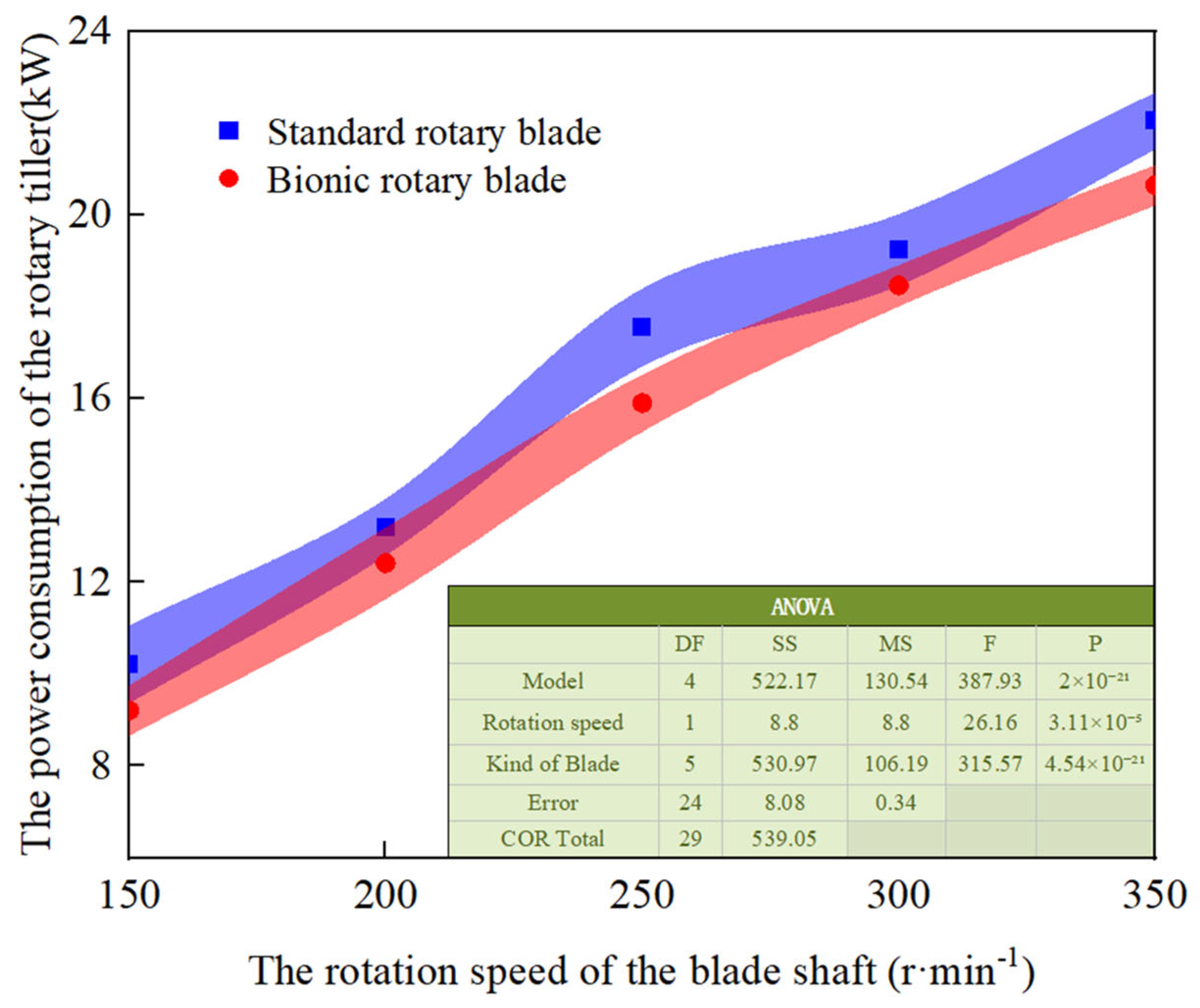
3.2.2. Effect of Rotation Speed of the Blade Shaft on Power Consumption

The effect of rotation speed of the blade shaft on power consumption under different blade types is shown in Figure 7. From the ANOVA results, it could be seen that the blade type and forward speed of the rotary tiller had a significant effect on power consumption (p less than or equal to 0.05). As the rotation speed of the blade shaft increased, the power consumption of the device also rose. This could be attributed to several factors. First, an increase in the rotation speed of the blade shaft led to a higher frequency of collisions between the blade and the soil per unit of time. Consequently, the rotary tillage needed to overcome a greater soil shear force. Additionally, at a higher rotation speed of the blade shaft, the blade threw the soil to a higher and further distance, which resulted in increased kinetic energy consumption. Moreover, the friction between the components of the blade shaft during high-speed rotation caused greater energy loss, thereby leading to more pronounced mechanical vibrations [27,28]. When the rotation speed of the blade shaft was 150 r∙min−1, the power consumption of the rotary tiller was minimized. Specifically, the power consumption of rotary tillage with bionic blades and standard blades reached the minimum values of 10.22 kW and 9.21 kW, respectively. As the rotation speed of the blade shaft increased further, the ability of the bionic blade reduced obstruction and power consumption became more evident. For example, when the rotation speed of the blade shaft was 250 r∙min−1, the power consumption of the rotary tiller with bionic blades could be reduced by 9.3% compared to that of the rotary tiller with standard blades. When the rotation speed of the blade shaft reached 350 r∙min−1, the power consumption of the rotary tiller was maximized. At this speed, the power consumption of the rotary tiller with bionic blades and the rotary tiller with standard blades reached the highest values of 22.06 kW and 20.66 kW, respectively.
The effect of the rotation speed of the blade shaft on the power consumption of rotary tillers under different blade types is shown in Figure 7. The results show that p less than or equal to 0.05 indicates that the blade type had a significant effect on the power consumption of the rotary tiller. The reason for this was that the hemispherical bump of the rotary tiller with bionic blades could create cyclic perturbations in the soil, disrupting the adhesion layer between the soil and the blade surface [29]. This reduced the additional load caused by soil adhesion and lowered the soil particle retention time. The bump structure was thus an effective choice for reducing the power consumption of the rotary tiller with bionic blades. Additionally, the bump structure could form vortices during rotation, accelerating the process of soil casting off, shortening the contact time between the blade and the soil, and avoiding repeated cutting. This, in turn, helped to reduce ineffective power consumption. The rotary blade with bionic bump units consistently exhibited lower power consumption at different rotation speeds. This reduction in power consumption was primarily due to the bionic structure reducing the resistance of cutting soil. In the low-speed range of 150–250 r∙min−1, the bump structure significantly reduced adhesive resistance by disrupting the continuous soil shear plane. When the rotation speed exceeded 250 r∙min−1, the micro-turbulence effect generated by these bumps loosened the soil in advance, thereby reducing cutting power consumption.

3.3. Effect of Test Factors on the Ground Surface Flatness

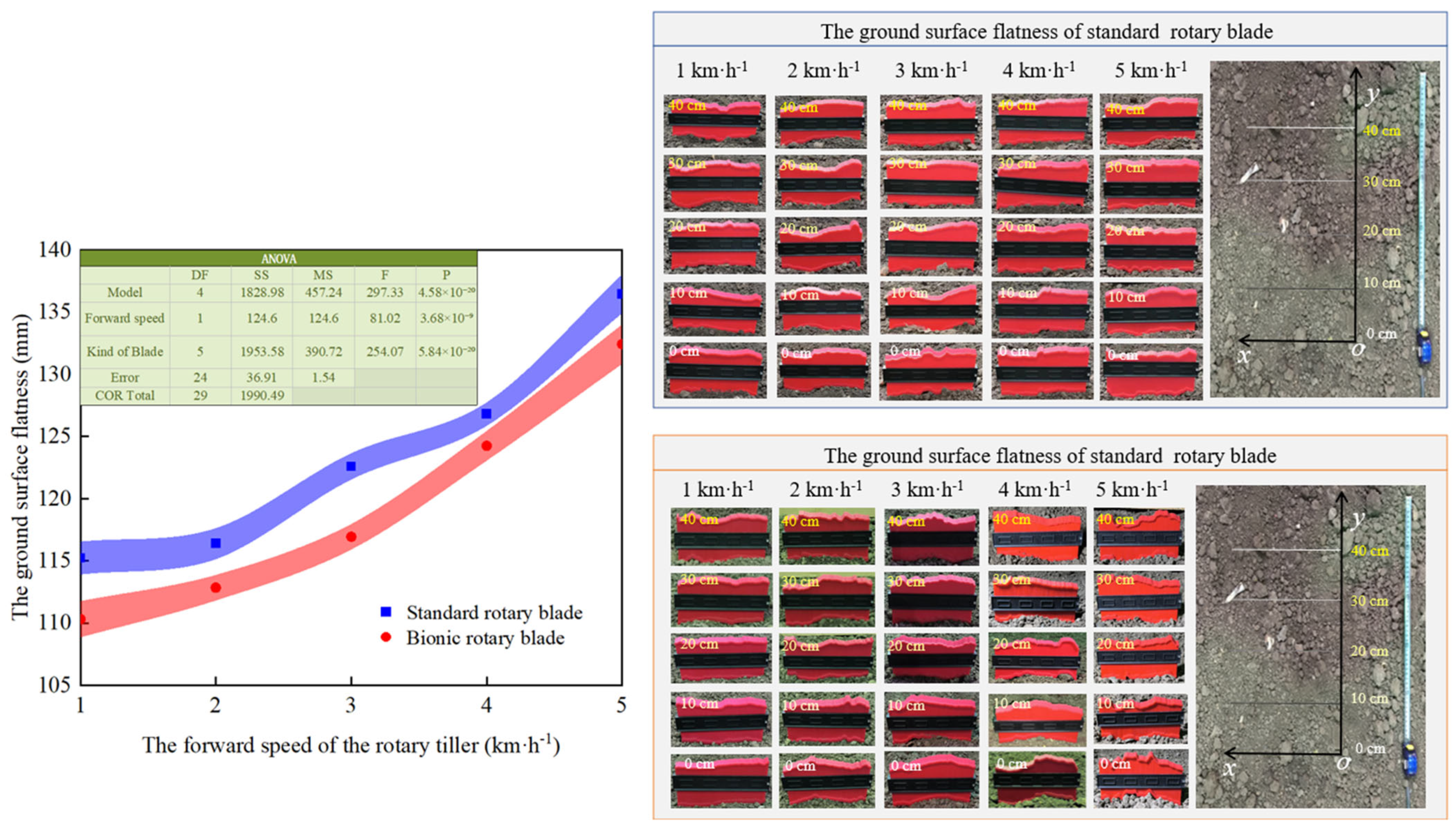
3.3.1. Effect of Forward Speed of Rotary Tiller on Ground Surface Flatness

The effect of the forward speed of the rotary tiller on the ground surface flatness under different blade types is shown in Figure 8. From the ANOVA results, it could be seen that the forward speed of the rotary tiller had a significant effect on ground surface flatness (p less than or equal to 0.05). The analysis revealed that both the rotary tillers with bionic blades and standard blades exhibited a decrease in ground surface flatness with the increasing forward speed of the rotary tiller. Specifically, as the forward speed of the rotary tiller increased from 1 km∙h−1 to 5 km∙h−1, the contact time between the blade and the soil decreased by approximately 80%. This reduction in contact time was insufficient for the shear action to adequately fragment the soil, resulting in non-uniform soil clod sizes, which in turn led to the formation of local mounds and depressions and ultimately reduced ground surface flatness [30]. When the rotary tillage operated at a forward speed lower than 4 km∙h−1, the soil was processed in a laminar flow state under the action of the blade, allowing the crushed soil to be spread uniformly. However, as the forward speed increased, the soil flow state became turbulent [31]. Under the same rotation speed of the blade shaft, an increase in forward speed led to a larger pitch of the rotary blade cutting through the soil, creating surface grooves of uneven depth, which negatively affected the ground surface flatness. At low forward speeds, 60–70% of the cutting energy of the blades was employed for soil crushing; in contrast, at high forward speeds, more than 40% of the energy was converted into soil-throwing kinetic energy [32]. This results in an imbalance between the energy allocated for crushing and throwing [33], weakening the stability of the blade’s operation and making it more likely to form a wavy surface, thereby reducing the ground surface flatness.
The effect of the forward speed of the rotary tiller on the ground surface flatness under different blade types is shown in Figure 8. The results show that p less than or equal to 0.05 indicates that the blade type had a significant effect on the power consumption of the rotary tiller. When the forward speed of the rotary tiller was 1 km∙h−1, the highest ground surface flatness was achieved after rotary tilling. The ground surface flatness of the rotary tillers with bionic blades and standard blades were 110 mm and 115 mm, respectively. Conversely, when the forward speed was increased to 5 km∙h−1, the ground surface flatness values for the rotary tillers with bionic blades and standard blades were 136 mm and 132 mm, respectively. To effectively address the issue of low ground surface flatness, under the condition that the forward speed of the rotary tiller was 3 km∙h−1, the rotary tiller with bionic blades demonstrated the best improvement in ground surface flatness, with a 3.5% increase compared to the standard blade. This improvement was attributed to the unique three-stage “collision-shear-tear” crushing mode of the bionic blade during rotation. In the first stage, the bump structure of the bionic blade impacted the soil normally, destroying its structure through the application of normal force. Subsequently, the side edge of the bump structure applied shear force to the soil block, cutting the loosened soil. Finally, the tail part of the bump structure accelerated the peeling off of the soil block layer by layer. This three-stage process effectively prevented incomplete soil crushing that could occur due to insufficient contact time at high speeds. Additionally, the bump structure of the bionic blade induced orderly soil flow [34], mitigating the turbulent flow caused by increased forward speed, reducing soil dispersion, and thereby enhancing the ground surface flatness [35]. The bionic bump units significantly enhanced ground surface flatness at the different forward speeds of the rotary tiller. This contributed to their unique dynamic soil-handling mechanism. When the forward speed of the rotary tiller was below 3 km∙h−1, these bionic bump units employed a layered soil-breaking approach that combined lifting and shearing actions. This could effectively prevent the soil displacement typically caused by forced tilling action. When the forward speed of the rotary tiller exceeded 3 km∙h−1, an optimal resonance occurred between the blade rotation and forward motion of the rotary tiller. In this state, the bump structure initiated a sophisticated three-phase process. It began with the initial compression of the soil, followed by directional dispersion, and ultimately culminated in effective leveling. This mechanism could significantly enhance ground surface flatness and optimize overall tillage quality.

3.3.2. Effect of the Rotation Speed of the Blade Shaft on Ground Surface Flatness

The effect of the rotational speed of the blade shaft on ground surface flatness under different blade types is shown in Figure 9. From the ANOVA results, it could be seen that the rotation speed of the blade shaft had a significant effect on ground surface flatness (p less than or equal to 0.05). For both rotary tillers with bionic blades and standard blades, the ground surface flatness increased with the increase in the rotation speed of the blade shaft. This phenomenon could be attributed to several factors. As the rotation speed of the blade shaft increased, the soil crushing effect was enhanced. Higher rotation speeds of the blade shaft increased the impact and shear forces applied to the soil, leading to finer soil fragmentation and more uniform particle distribution. Additionally, the increased speed enhanced soil mobility, allowing the soil to be more easily thrown and evenly distributed, thereby reducing the occurrence of unevenness. The blades also acted on the soil more frequently per unit time, resulting in repeated cutting and mixing of the soil. The higher rotation speed of the blade shaft further reduced soil buildup near the cutter, minimizing localized highs and lows. When the rotation speed of the blade shaft was 150 r∙min−1, the ground surface flatness after operation of the rotary tillers with bionic blades and standard blades reached its minimum, with values of 151 mm and 158 mm, respectively. Conversely, when the rotation speed of the blade shaft was 350 r∙min−1, the ground surface flatness after operation was at its maximum, with values of 102 mm and 109 mm, respectively.
The effect of rotation speed of the blade shaft on the ground surface flatness under different blade types is shown in Figure 9. The results show that p less than or equal to 0.5 indicates that the blade type had a significant effect on the power consumption of the rotary tiller. At the same rotation speed of the blade shaft, the ground surface flatness of the rotary tiller with bionic blades was consistently higher than that of the rotary tiller with standard blades. For instance, at a rotation speed of the blade shaft of 150 r∙min−1, the surface flatness value of the rotary tiller with bionic blades was 7 mm lower than that of the rotary tiller with standard blades. At a rotation speed of the blade shaft of 350 r∙min−1, the ground surface flatness of the rotary tiller with bionic blades was 6.5% higher than that of rotary tiller with standard blades. This superior performance of the bionic blade could be explained by its unique design. At high rotation speed of the blade shaft, the hemispherical bump structure induced the airflow to form an attached vortex [36], which generated a centripetal force on the thrown soil particles. This significantly reduced the edge buildup caused by long-distance throwing [37]. Additionally, the hemispherical projection increased the contact area between the blade and the soil [38], converting more cutting energy into the potential energy for lifting the soil rather than the kinetic energy for lateral throwing [39]. This conversion reduced the falling height of the soil, thereby decreasing the vertical impact force, which was conducive to the natural settlement and leveling of soil particles [40]. Moreover, the hemispherical bionic structure effectively reduced the coefficient of friction between the soil and the metal [41], allowing more energy to be utilized for fine soil crushing, which ultimately improved the leveling of the soil. The blades with bionic bumps could achieve higher ground surface flatness at different rotation speeds of the blade shaft. This was primarily attributed to the bionic structure controlling the soil flow. At lower rotation speeds of 150–200 r∙min−1, the bump structure could break up the soil in progressive layers, thereby avoiding a soil accumulation phenomenon caused by the centralized tilling of traditional blades. At higher rotation speeds of 200–300 r∙min−1, the bionic bumps generated a directional soil flow that allowed soil to fall back evenly. When the rotation speed of the blade shaft reached 350 r∙min−1, the ability of the bionic unit to induce soil to fall back evenly would be enhanced. This mechanism could avoid soil accumulation at low rotation speeds, inhibit excessive scattering at high rotation speeds, and effectively enhance ground surface flatness. The bionic blade designed by Yang Yuwan [25], based on the combined structure of the mole multi-toe, exhibited a similar pattern in ground surface flatness changes as observed in this study. For both types of bionic blades, the ground surface flatness increased with the rotation speed of the blade shaft. The pufferfish bionic blade achieved the best ground surface flatness at the rotation speed of 350 r∙min−1. The mole multi-toe blade exhibited a similar trend at the same rotation speed, attributed to the higher frequency of soil breakage. At low forward speeds of 1 km∙h−1, both types of bionic blades exhibited poor ground surface flatness due to excessive soil fragmentation and repetitive cutting. The pufferfish bionic blade exhibited a more significant 3.5% improvement in flatness compared to the traditional blade at the forward speed of 3 km∙h−1. Its bump structure reduced soil accumulation by directing soil flow in an orderly manner. In contrast, the mole multi-toe blade had less ground surface flatness at high forward speed, possibly due to the complex shear action of the multi-toe structure. The pufferfish bionic blade reduced soil adhesion and promoted soil flow, causing the superior ground surface flatness at higher forward speed. Meanwhile, the uniformity of the soil block was poor after cutting by the mole multi-toe blade, resulting in decreased ground surface flatness at higher forward speed. Therefore, it could be more suitable for efficient deep loosening of hard soils.
The pufferfish bionic blade surface was optimized by the bump structure, which could reduce soil adhesion and friction, thereby lowering power consumption and enhancing fuel efficiency. It also could improve the effect of breaking soil and the overall quality of rotary tillage. These features align with the goals of precision agriculture, help reduce carbon emissions, and support sustainable farming practices. The bionic blade had only been tested for drag reduction and rotary tillage quality under clay soil conditions in a soil bin. Under different soil types, the performance of the bionic knife will continue to be tested in the future. Efforts will be made to identify more cost-effective processing methods to reduce the manufacturing cost of the bionic rotary blade, thereby accelerating its widespread adoption.

4. Conclusions

Inspired by the non-smooth surface of the pufferfish, we designed bionic rotary tillage blades with strategically arranged bumps. Through a single-factor soil bin test, the effects of the forward speed of the rotary tiller and the rotation speed of the blade shaft on both the power consumption of the rotary tiller and the ground surface flatness were examined. The performance of the rotary tiller equipped with these bionic blades was then compared to that of the rotary tiller fitted with standard IT225 blades. The results conclusively demonstrated that the bionic blade can significantly reduce the power consumption of the rotary tiller while also enhancing the flatness of the ground surface.
The power consumption of the rotary tiller with the bionic blades initially decreased, then increased, and finally decreased with the increase in the forward speed of the rotary tiller. Conversely, the power consumption of the rotary tiller consistently increased with the increase in rotation speed of the blade shaft. Bionic tillage blades reduced consumption by 9.4% under optimal conditions compared to traditional tillage blades.
The ground surface flatness shows a positive correlation with the forward speed of the rotary tiller, yet it exhibits a negative correlation with the rotation speed of the blade shaft. The rotary tiller had the most significant performance in improving ground surface flatness at optimal operating conditions, with a 6.5% improvement in ground surface flatness. This innovative design mechanism enhances the uniformity of the ground surface, thus significantly improving its flatness. The findings of this research offer novel insights and valuable references for the development of energy-saving tillage tools in the agricultural sector. The bionic rotary blade, despite its advantages, still faces limitations regarding its applicability in different soil conditions and its high manufacturing cost. Future research will focus on establishing a refined model of soil–rotary-blade interaction to better understand the complex dynamics. This will involve exploring the effect of additional factors such as the height and inclination of the bionic unit on the drag reduction. The goal is to enhance the adaptability of the blades across various soil conditions. Additionally, efforts will be made to identify more cost-effective processing methods to reduce the manufacturing cost of the bionic rotary tiller, thereby accelerating its widespread adoption.

Author Contributions

Project administration, X.F.; conceptualization, Y.G. and C.X.; methodology, J.T.; writing—original draft preparation, Y.Q. and Y.G.; writing—review and editing, Y.Q. and Q.W. All authors have read and agreed to the published version of the manuscript.

Funding

This work was supported by the National Natural Science Foundation of China (Grant No. 52205253),the National Natural Science Foundation of Heilongjiang Province of China (Grant No.LH2022E007), the Heilongjiang Provincial Key Research and Development Program (Grant No.2022ZX05B04), and the Key Laboratory of High Efficient Seeding and Harvesting Equipments, Ministry of Agriculture and Rural Affairs of the People’s Republic of China, Northeast Agricultural University, Harbin 150030, China (Grant No. 55200412).

Institutional Review Board Statement

Not applicable.

Data Availability Statement

The data presented in this study are available on request from the corresponding author.

Acknowledgments

Thanks to the “National Natural Science Foundation of China, the National Natural Science Foundation of Heilongjiang Province of China, the Young Talents Project of Northeast Agricultural University and the Key Laboratory of High Efficient Seeding and Harvesting Equipments” for the financing of this research.

Conflicts of Interest

The authors declare no conflict of interest.

References

  1. Koller, K.; El Titi, A. Techniques of Soil Tillage. In Soil Tillage in Agroecosystems; CRC Press: Boca Raton, FL, USA, 2003; pp. 1–25. [Google Scholar]
  2. Zhang, X.Y.; Zhang, L.X.; Hu, X.; Wang, H.; Shi, X.B.; Ma, X. Simulation of Soil Cutting and Power Consumption Optimization of a Typical Rotary Tillage Soil Blade. Appl. Sci. 2022, 12, 8177. [Google Scholar] [CrossRef]
  3. Liu, G.Y.; Xia, J.F.; Zheng, K.; Cheng, J.; Wei, Y.S.; Guo, L.W.; Li, X.F.; Zhang, J.M. Design and experiments of the barrier type rotary anti-adhesion blade roller with vibration crosspiece. Trans. Chin. Soc. Agric. Eng. 2022, 38, 29–40. [Google Scholar]
  4. Xiong, P.Y.; Yang, Z.; Sun, Z.Q.; Zhang, Q.Q.; Huang, Y.Q.; Zhang, Z.W. Simulation analysis and experiment for three-axis working resistances of rotary blade based on discrete element method. Trans. Chin. Soc. Agric. Eng. 2018, 34, 113–121. [Google Scholar]
  5. Sun, J.Y.; Zhang, Z.J.; Tong, J.; Jia, H.L. Application of Bionic Technologies for Soil-Engaging Tillage Components in Northeast China. Bio-Inspired Surf. Appl. 2016, 555–578. [Google Scholar] [CrossRef]
  6. Xu, Z.H.; Qi, H.Y.; Gao, P.; Wang, S.; Liu, X.T.; Ma, Y.H. Biomimetic Design of Soil-Engaging Components: A Review. Biomimetics 2024, 9, 358. [Google Scholar] [CrossRef]
  7. Yu, H.Y.; Han, Z.W.; Zhang, J.Q.; Zhang, S.J. Bionic design of tools in cutting: Reducing adhesion, abrasion or friction. Wear 2021, 482, 203955. [Google Scholar] [CrossRef]
  8. Tan, Y.; Liu, S.; Ma, S.C. Application of Bionics Engineering in Innovative design of Agricultural Machinery. In Proceedings of the 2020 ASABE Annual International Meeting, Virtual, 13–15 July 2020; p. 1. [Google Scholar]
  9. Hu, J.P.; Xu, L.Z.; Yu, Y.; Lu, J.; Han, D.L.; Chai, X.Y.; Wu, Q.H.; Zhu, L.J. Design and Experiment of Bionic Straw-Cutting Blades Based on Locusta Migratoria Manilensis. Agriculture 2023, 13, 2231. [Google Scholar] [CrossRef]
  10. Li, J.; Li, H.C.; Chen, Y.Y.; Lin, P.Y.; Zhang, Q.Q.; Cheng, Y.; Yang, Z.; Huang, G.W. Research on Ditching Mechanism of Self-Excited Vibration Ditching Machine. Agronomy 2023, 13, 905. [Google Scholar] [CrossRef]
  11. Guo, J.; Zhang, Q.Y.; Muhammad, S.M.; Ji, C.Y.; Zhao, Z. Design and experiment of bionic mole’s toe arrangement serrated blade for soil-rototilling and straw-shattering. Trans. Chin. Soc. Agric. Eng. 2017, 33, 43–50. [Google Scholar]
  12. Santhanam, R. Biology and Ecology of Toxic Pufferfish; Apple Academic Press: Palm Bay, FL, USA, 2017. [Google Scholar]
  13. Barthlott, W.; Neinhuis, C. Purity of the Sacred Lotus, or Escape from Contamination in Biological Surfaces. Planta 1997, 202, 1–8. [Google Scholar] [CrossRef]
  14. Genzer, J.; Marmur, A. Biological and Synthetic Self-Cleaning Surfaces. MRS Bull. 2008, 33, 742–746. [Google Scholar] [CrossRef]
  15. Gao, T.Y.; Xiong, Z.X.; Li, Z.L.; Huang, X.; Liu, Y.; Cai, K.W. Precise underwater fish measurement: A geometric approach leveraging medium regression. Comput. Electron. Agric. 2024, 221, 108932. [Google Scholar] [CrossRef]
  16. Zhang, Y.S.; Fan, D.L.; Feng, X.M.; Hu, Y.S.; Shi, J.; Tian, G.Z. Drag reduction performance and mechanism of flexible conical microstructure film inspired by pufferfish epidermis. Ocean Eng. 2023, 271, 113760. [Google Scholar] [CrossRef]
  17. Liu, C.Q. Optimization of Drag Reduction Elements Model of Bionic Puffer Spines and Study of Spatial Flow Field Characteristics. Ph.D. Thesis, Jiangsu University of Science and Technology, Zhenjiang, China, 2020. [Google Scholar]
  18. Zhou, S.; Jiang, L.; Dong, Z.C. Overflow Control for Sustainable Development by Superwetting Surface with Biomimetic Structure. Chem. Rev. 2023, 123, 2276–2310. [Google Scholar] [CrossRef] [PubMed]
  19. Six, J.; Elliott, E.T.; Paustian, K. Soil macroaggregate turnover and microaggregate formation: A mechanism for C sequestration under no-tillage agriculture. Soil Biol. Biochem. 2000, 32, 2099–2103. [Google Scholar] [CrossRef]
  20. GB/T 5669-2017; Rotary Tillage Machinery—Blades and Blade Holders. China National Standardization Administration: Beijing, China, 2017.
  21. Li, J.W.; Li, X.Y.; Hu, B.; Gu, T.L.; Wang, Z.J.; Wang, H.L. Analysis of the resistance reduction mechanism of potato bionic digging shovels in clay and heavy soil conditions. Comput. Electron. Agric. 2023, 214, 108315. [Google Scholar] [CrossRef]
  22. Zhu, Y.H. Research on the Working Mechanism and Consumption Reduction of Rotary Burial Blade Roller for Straw Returning. Ph.D. Thesis, Huazhong Agricultural University, Wuhan, China, 2020. [Google Scholar]
  23. Yu, C.Y.; Liu, J.; Zhang, J.; Xue, K.; Zhang, S.; Liao, J.; Tai, Q.L.; Zhu, D.Q. Design and optimization and experimental verification of a segmented double-helix blade roller for straw returning cultivators. J. Chin. Inst. Eng. 2021, 44, 379–387. [Google Scholar] [CrossRef]
  24. Zhang, J.J.; Feng, G.H.; Yan, X.H.; He, Y.D.; Liu, M.N.; Xu, L.Y. Cooperative control method considering efficiency and tracking performance for unmanned hybrid tractor based on rotary tillage prediction. Energy 2024, 288, 129874. [Google Scholar] [CrossRef]
  25. Yang, Y.W.; Tong, J.; Ma, Y.H.; Li, M.; Jiang, X.H.; Li, J.G. Design and Experiment of Bionic Soil-cutting Blade Based on Multi-claw Combination of Mole Rat. Trans. Chin. Soc. Agric. Mach. 2018, 49, 122–128. [Google Scholar]
  26. Liu, X.L.; Liu, M.; He, G.H.; Yan, F.G.; Cheng, Y.N.; Liu, L. Impact Damage Behavior of the Cemented Carbide Insert in the Heavy Cutting Process. J. Mech. Eng. 2014, 50, 175–185. [Google Scholar] [CrossRef]
  27. Liu, M.Z.; Xie, F.P.; Liu, D.W.; Wang, X.S. Analysis and experiment of the power of blade roller in reverse-rotary ditching machine based on the granular scale effect. Trans. Chin. Soc. Agric. Eng. 2024, 40, 83–92. [Google Scholar]
  28. Dıaz-Zorita, M.; Perfect, E.; Grove, J.H. Disruptive methods for assessing soil structure. Soil Tillage Res. 2002, 64, 3–22. [Google Scholar] [CrossRef]
  29. Bartzanas, T.; Kacira, M.; Zhu, H.; Karmakar, S.; Tamimi, E.; Katsoulas, N.; Lee, I.B.; Kittas, C. Computational fluid dynamics applications to improve crop production systems. Comput. Electron. Agric. 2013, 93, 151–167. [Google Scholar] [CrossRef]
  30. Yuan, Y.W.; Wang, J.Y.; Zhang, X.; Zhao, S.H. Effect of rotary speed on soil and straw throwing process by stubble-crushing blade for strip tillage using DEM-CFD. Agriculture 2023, 13, 877. [Google Scholar] [CrossRef]
  31. Lin, H. Linking principles of soil formation and flow regimes. J. Hydrol. 2010, 393, 3–19. [Google Scholar] [CrossRef]
  32. Xu, H.B.; Zhang, P.; Hu, Z.C.; Mao, E.R.; Yan, J.C.; Yang, H.G. Analysis of dust diffusion from a self-propelled peanut combine using computational fluid dynamics. Biosyst. Eng. 2022, 215, 10. [Google Scholar] [CrossRef]
  33. Montero, E. Rényi dimensions analysis of soil particle-size distributions. Ecol. Model. 2005, 182, 305–315. [Google Scholar] [CrossRef]
  34. Salokhe, V.M.; Ramalingam, N. Effects of direction of rotation of a rotary tiller on properties of Bangkok clay soil. Soil Tillage Res. 2001, 63, 65–74. [Google Scholar] [CrossRef]
  35. Zheng, J.; Huang, H.; Liao, Y.T.; Wang, L.; Yuan, J.C.; Lin, J.X.; Liao, Q.X. Progress and suggestions on full mechanization of rapeseed production in the middle reaches of the Yangtze River. Chin. J. Oil Crop Sci. 2024, 46, 245–259. [Google Scholar]
  36. Yurishchev, A.; Ullmann, A.; Brauner, N. Experiments and modeling of droplets motion induced by turbulent air flow on inclined surfaces. Exp. Therm. Fluid Sci. 2023, 140, 110763. [Google Scholar] [CrossRef]
  37. Perdok, U.D.; Kouwenhoven, J.K. Soil-tool interactions and field performance of implements. Soil Tillage Res. 1994, 30, 283–326. [Google Scholar] [CrossRef]
  38. Milkevych, V.; Munkholm, L.J.; Chen, Y.; Nyord, T. Modelling approach for soil displacement in tillage using discrete element method. Soil Tillage Res. 2018, 183, 60–71. [Google Scholar] [CrossRef]
  39. Zeng, Z.W.; Chen, Y. Simulation of straw movement by discrete element modelling of straw-sweep-soil interaction. Biosyst. Eng. 2019, 180, 25–35. [Google Scholar] [CrossRef]
  40. Schmidt, J.; Werner, M.; Schindewolf, M. Wind effects on soil erosion by water—A sensitivity analysis using model simulations on catchment scale. Catena 2017, 148, 168–175. [Google Scholar] [CrossRef]
  41. Zhang, R.; Sun, X.M.; Han, D.L.; Zhuang, R.; Zhang, H.; Ma, J.; Wen, L.G.; Zou, M. A bionic mechanical foot with adaptive variable postures travelling on sand. J. Terramech. 2023, 107, 61–74. [Google Scholar] [CrossRef]
Figure 1. Design of the rotary blade that imitates the surface of a pufferfish.
Agriculture 15 00938 g001
Figure 2. System of testing the performance of rotary tiller.
Agriculture 15 00938 g002
Figure 3. EDEM simulation of rotary blades with bionic bumps of different sizes.
Agriculture 15 00938 g003
Figure 4. Establishment of the datum plane in ground surface flatness determination.
Agriculture 15 00938 g004
Figure 5. The torque of rotary blades with bionic bump units of different sizes.
Agriculture 15 00938 g005
Figure 6. Relationship between the power consumption of the rotary tiller and forward speed of the rotary tiller.
Agriculture 15 00938 g006
Figure 7. Relationship between the power consumption of the rotary tiller and the forward speed of the rotary tiller.
Agriculture 15 00938 g007
Figure 8. Relationship between the ground surface flatness and the forward speed of the rotary tiller (the different lines represent the five sampling points selected for the experiment in ascending order of distance).
Agriculture 15 00938 g008
Figure 9. Relationship between the ground surface flatness and the rotation speed of the blade shaft (the different lines represent the five sampling points selected for the experiment in ascending order of distance).
Agriculture 15 00938 g009
Table 1. Main parameters of standard IT225 rotary blade.
ParameterValue
Shank width300–0.5 mm
Shank thickness10 ± 0.5 mm
Hole diameter of shank12.5 + 0.5 mm
Turning radius of blade rollerR225-4 mm
Working width45–55 mm
Tangent plane bend angle120°
Thickness of cutting edge1.0~2.0 mm
Blade width12 mm
Table 2. Parameters of 1GKN-160 rotary tiller.
ParameterValue
Auxiliary power44.1–55.1 kW
Overall dimensions1850 × 800 × 850 mm
Total installed blades36
Width160 cm
Table 3. Material properties used in the DEM simulation.
PropertyValue
Density of soil particles (kg∙m−3)2550
Density of steel (kg∙m−3)7850
Poisson’s ratio of soil0.35
Poisson’s ratio of steel0.29
Shear modulus of soil (Pa)1 × 10⁸
Shear modulus of steel (Pa)7.9 × 10¹⁰
Coefficient of static friction of soil–soil0.83
Coefficient of rolling friction of soil–soil0.25
Coefficient of restitution friction for soil–soil0.66
Coefficient of static friction for soil–steel0.56
Coefficient of rolling friction for soil–steel0.18
Coefficient of restitution of soil–soil0.60
Cohesion interaction of soil–soil (J∙m−2)7.91
Cohesion interaction of soil–steel (J∙m−2)6.00
Table 4. Test factor levels.
ParameterIndex
12345
Rotation speed of the blade shaft/(r∙min−1)150200250300350
Forward speed of the rotary tiller/(km∙h−1)12345
Disclaimer/Publisher’s Note: The statements, opinions and data contained in all publications are solely those of the individual author(s) and contributor(s) and not of MDPI and/or the editor(s). MDPI and/or the editor(s) disclaim responsibility for any injury to people or property resulting from any ideas, methods, instructions or products referred to in the content.

