
Design of Dynamic Deep Sowing System for Peanut Planter with Double-Loop Feedback Fuzzy PID Control


Abstract
1. Introduction
2. Materials and Methods
2.1. Mechanical Structure and Working Principle
2.1.1. The Mechanical Structure of the Sowing Depth Control System
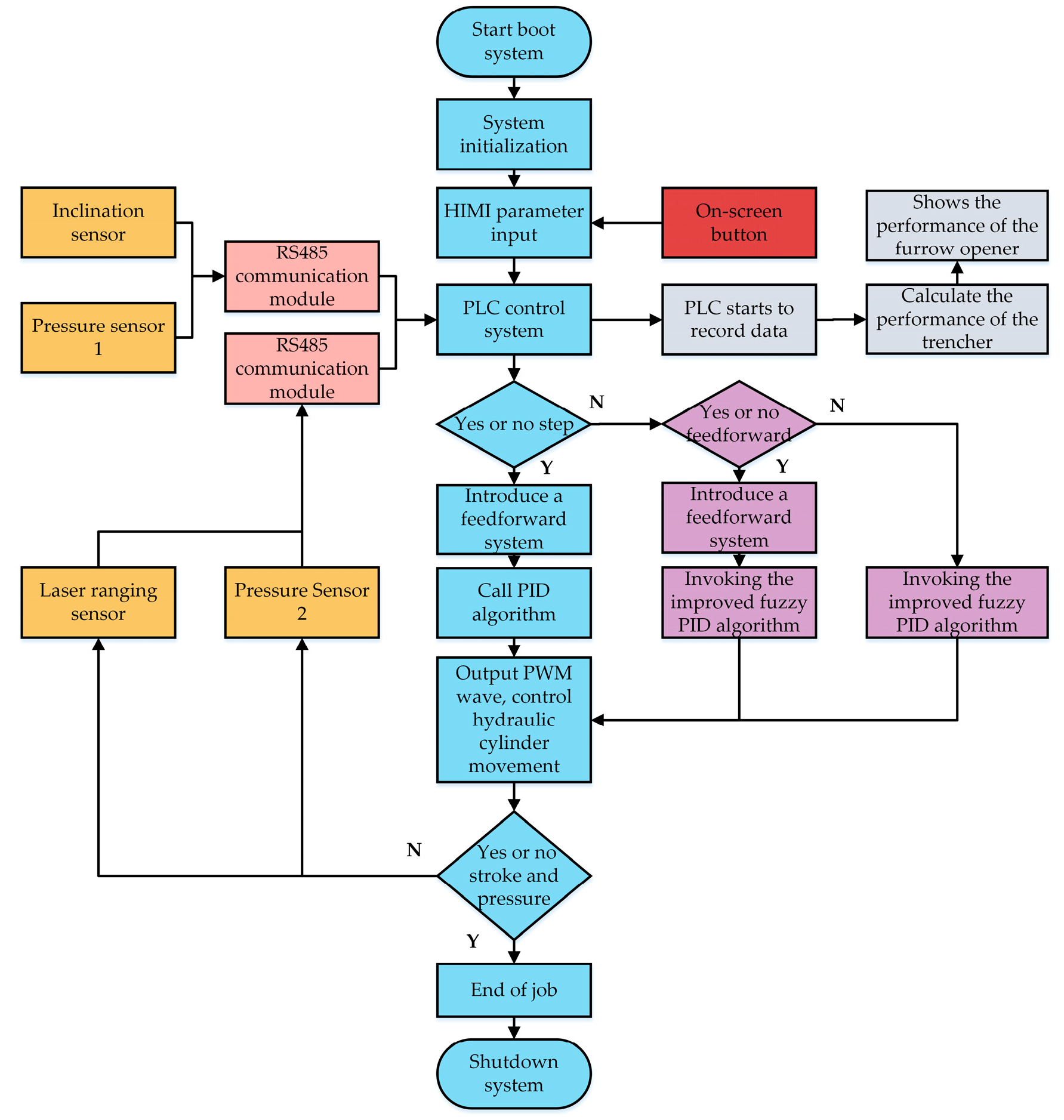
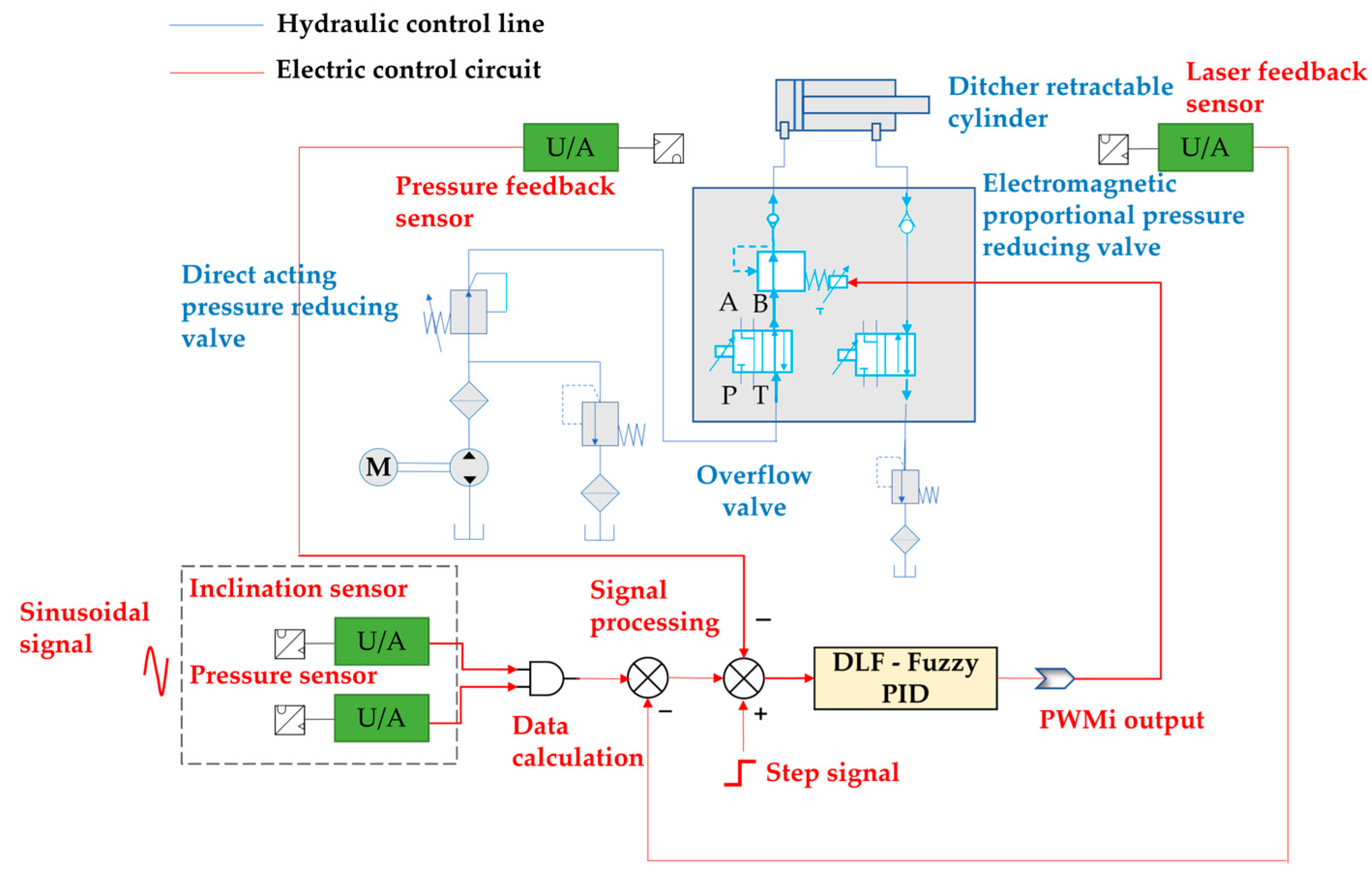
2.1.2. Working Principle of the Sowing Depth Control System
2.2. Key Structures and Working Mechanism
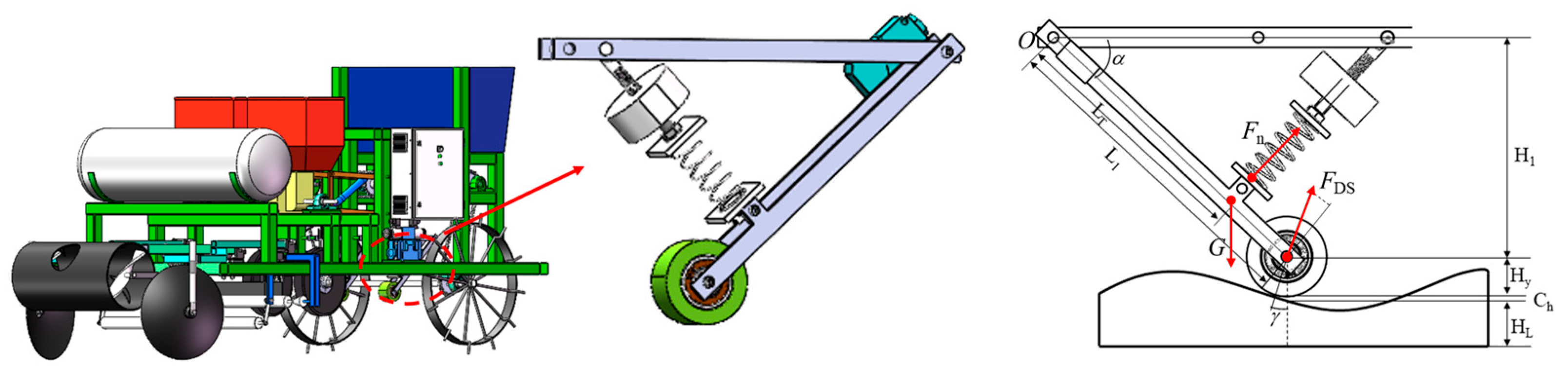
2.2.1. The Design of the Ridge Surface Profiling Mechanism
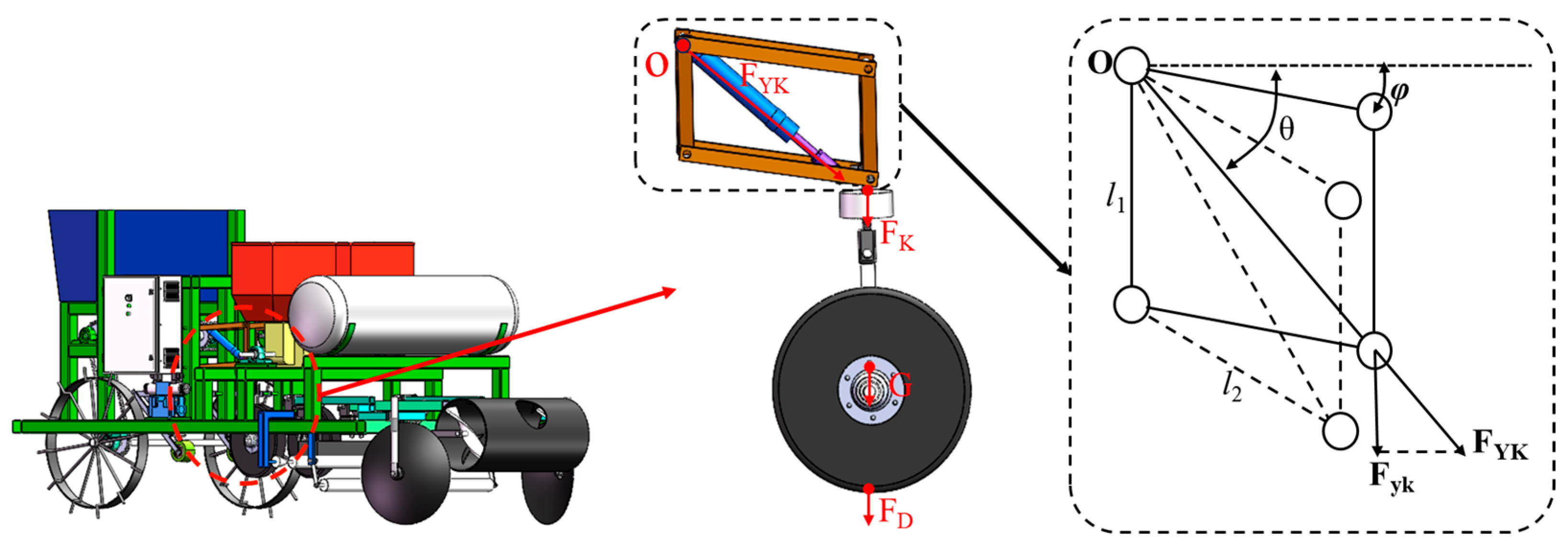
2.2.2. Design of Sowing Depth Adjustment Mechanism
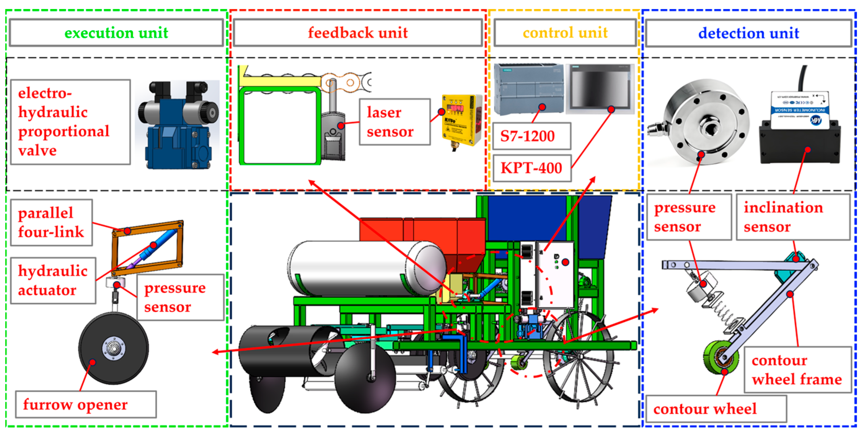
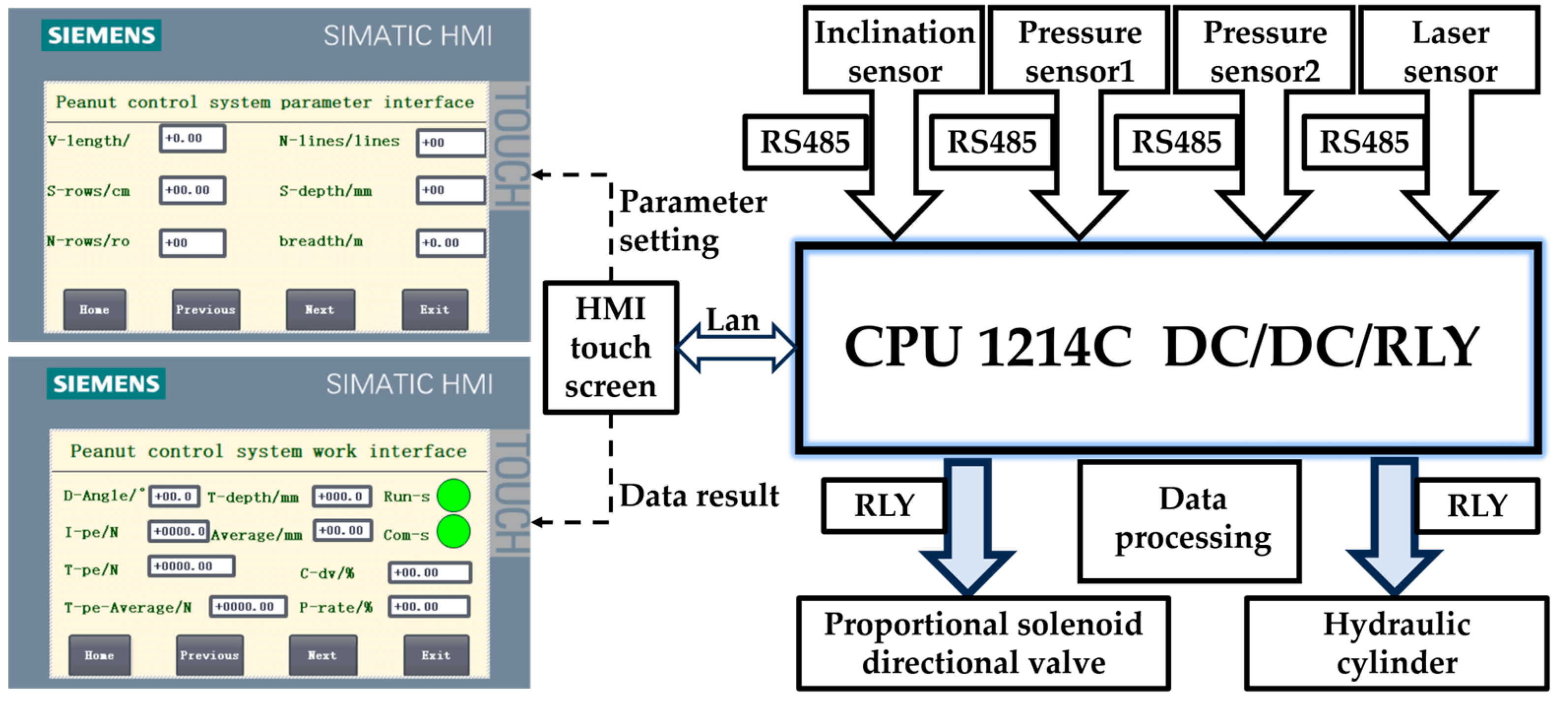
2.3. Hardware Design of Sowing Depth Control System
2.4. Control Strategy of Sowing Depth Control System
2.4.1. Mathematical Model of DLF-Fuzzy PID Control Strategy
- Mathematical Model Without Step Changes
- 2.
- Mathematical Model with Step Changes
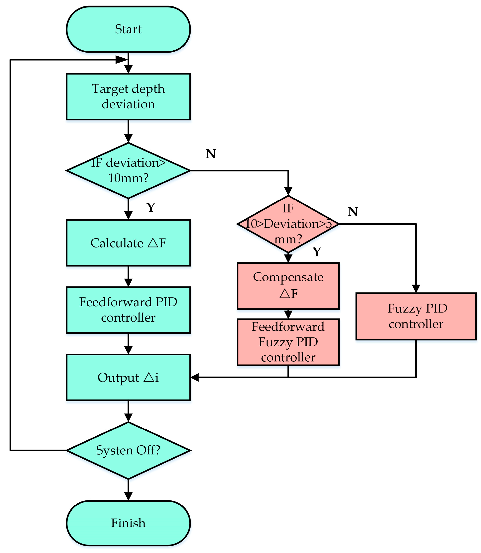
2.4.2. Design of DLF-Fuzzy PID Control Strategy
- 3.
- Fuzzy PID algorithm
- 4.
- PID algorithm with introduction of feedforward term
3. Results
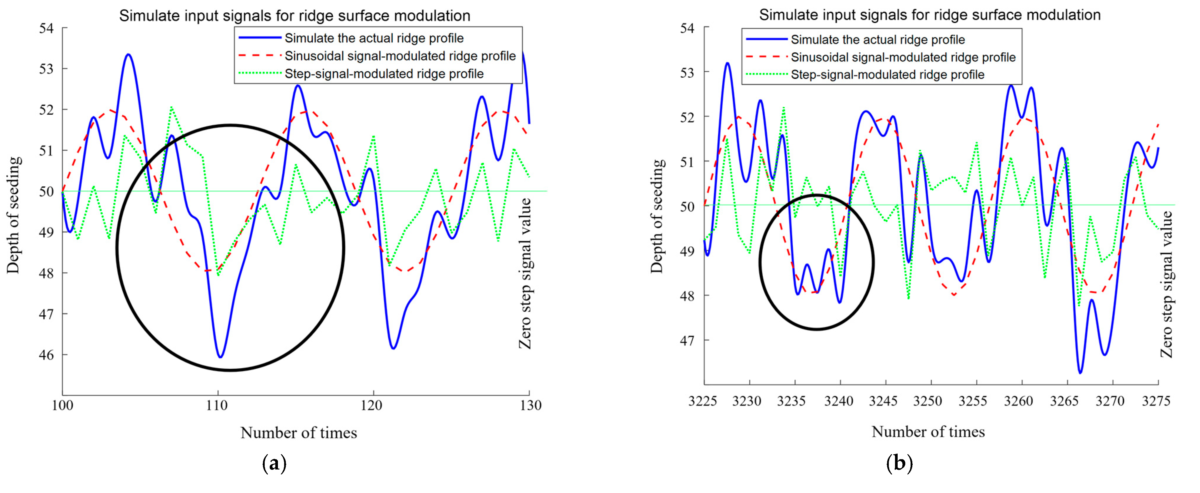
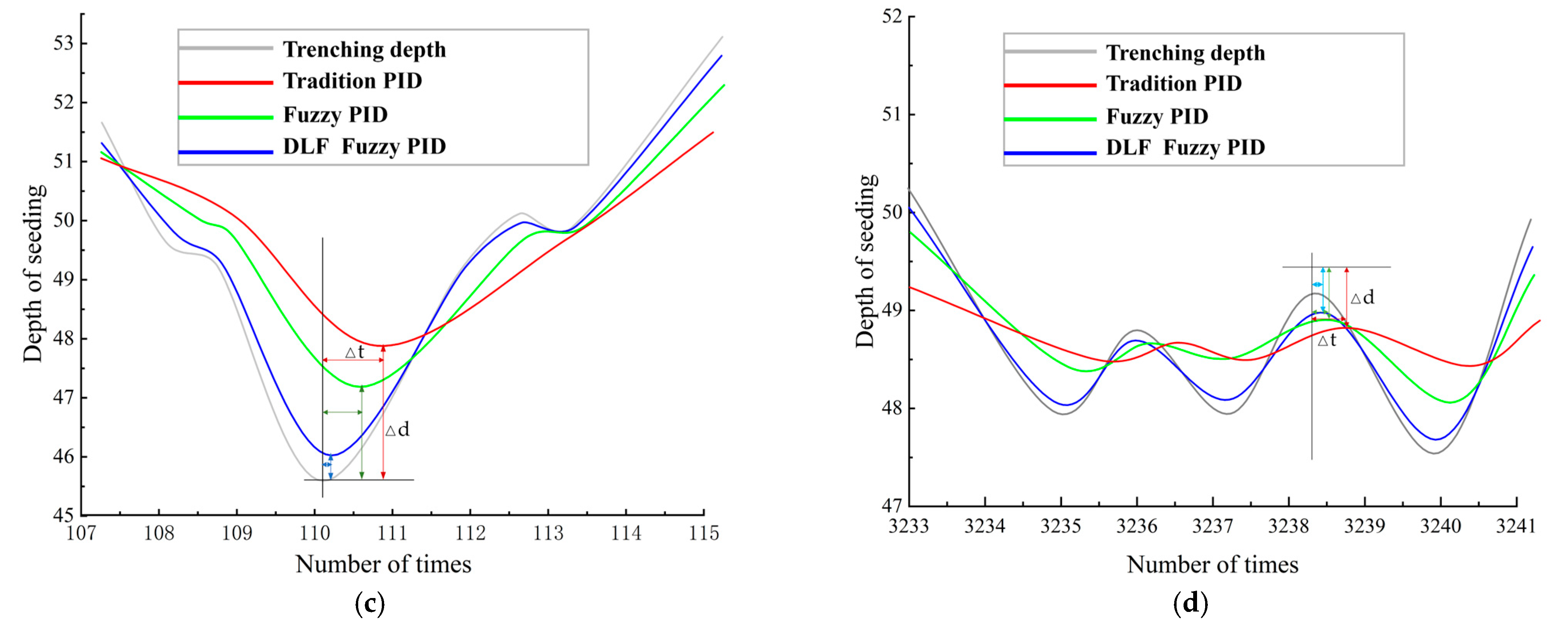
3.1. Simulation Verification and Analysis Based on MATLAB and AMESIM
3.2. Field Trials
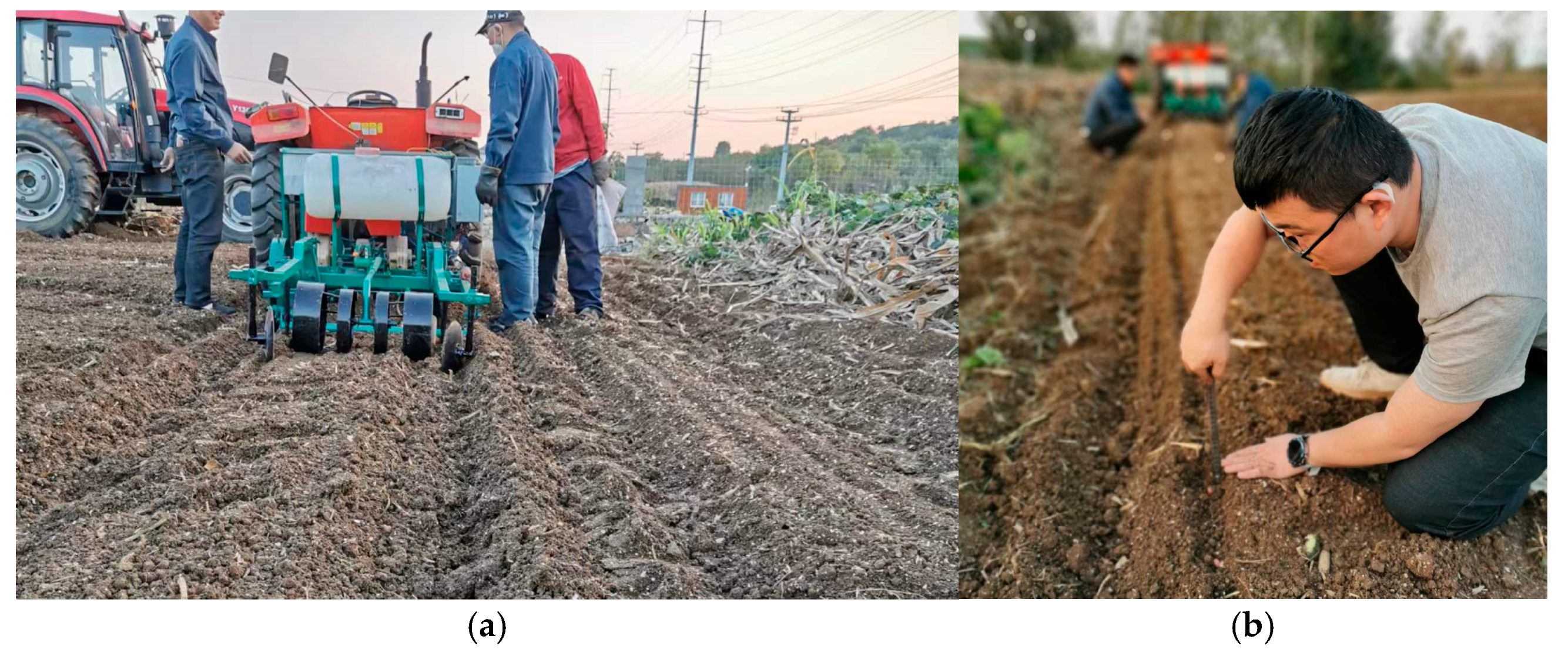
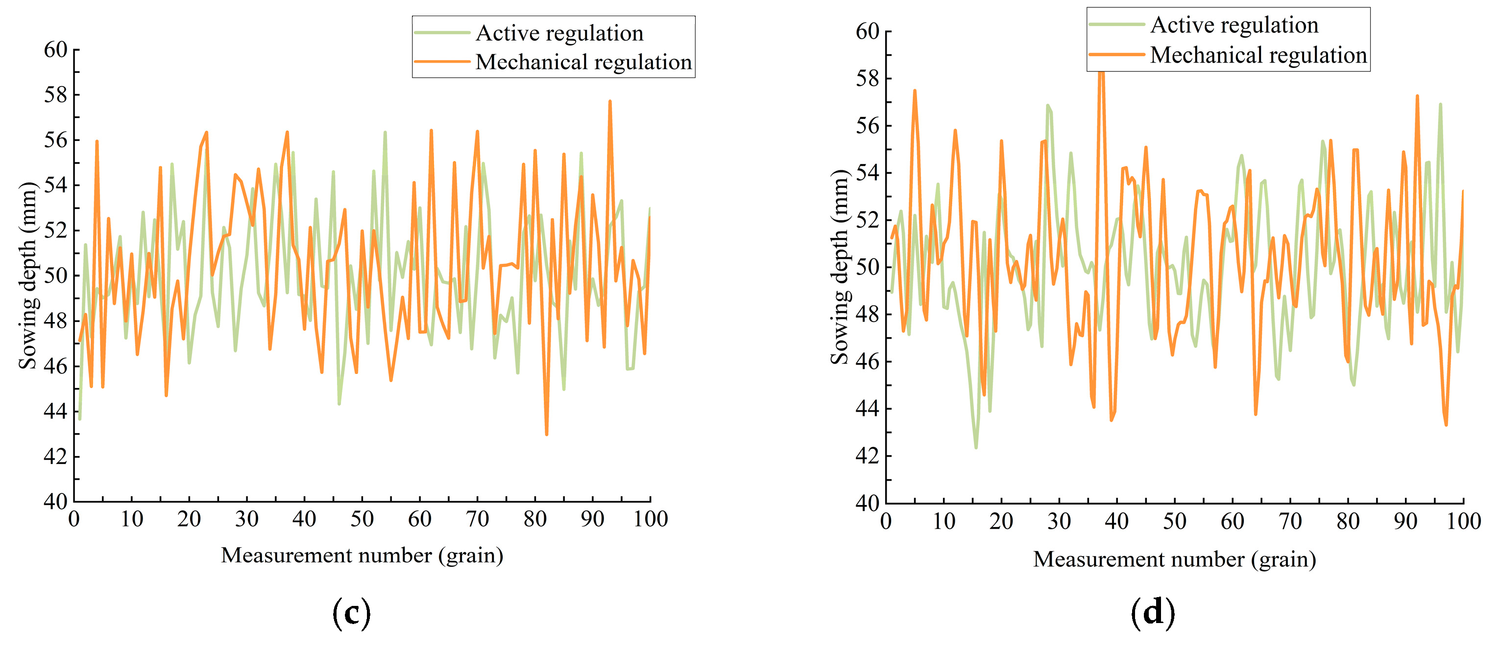
3.2.1. Test Methods
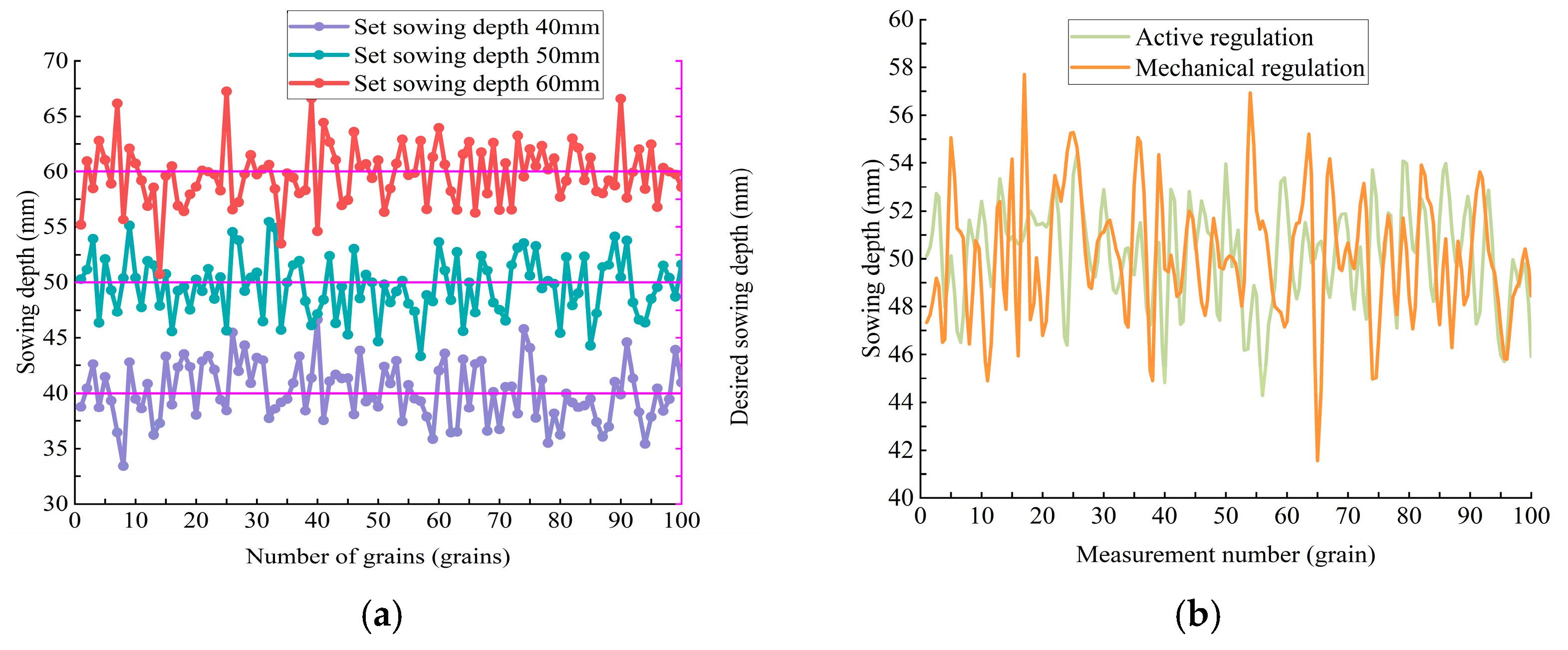
3.2.2. Calculation of Test Results

| Measuring Parameters | Operating Speed/(km/h) | Sowing Depth (mm) | Adjustment Mode | ||||
|---|---|---|---|---|---|---|---|
| Working speed/km/h | 3 | 4 | 5 | 3 | 3 | 3 | - |
| Sowing depth/mm | 50 | 50 | 50 | 40 | 50 | 60 | - |
| Average sowing depth/mm | 50.4 | 47.6 | 44.04 | 41.27 | 50.4 | 44.32 | Dynamic |
| 46.02 | 52.9 | 41.02 | 46.32 | 46.02 | 44.97 | Mechanical | |
| Sowing depth pass rate/% | 94.6 | 90.4 | 86.19 | 94.03 | 94.6 | 92.35 | Dynamic |
| 89.21 | 83.7 | 75.78 | 89.67 | 89.21 | 87.52 | Mechanical | |
| Standard deviation of sowing depth/mm | 2.38 | 3.74 | 6.19 | 2.36 | 2.38 | 4.67 | Dynamic |
| 4.53 | 5.67 | 7.95 | 5.02 | 4.53 | 5.39 | Mechanical | |
| Sowing depth coefficient of variation | 3.99 | 5.76 | 6.94 | 5.32 | 3.99 | 5.84 | Dynamic |
| 7.94 | 10.95 | 14.28 | 7.06 | 7.94 | 12.69 | Mechanical | |
3.2.3. Analysis of Test Results
4. Conclusions
- (1)
- Compared to traditional peanut planters, this study developed a dynamic sowing depth control system based on an existing planter. It uses hydraulic control to adjust downward pressure and includes a ridge height detection device.
- (2)
- A dynamic control mathematical model was established, incorporating angle–pressure–depth dynamics. A double-loop feedback fuzzy PID (DLF-Fuzzy PID) control strategy was designed. Co-simulation using Matlab-R2020b and Amesim-2020.2, along with a downward pressure control platform, validated the algorithm. It demonstrated significant advantages over traditional methods.
- (3)
- Field tests showed that the dynamic sowing depth adjustment outperformed traditional methods at speeds of 3–5 km/h. The dynamic system exhibited stable and reliable control performance. At 5 km/h, the sowing depth qualification rate exceeded 85%, laying the foundation for precision peanut planting.
Author Contributions
Funding
Institutional Review Board Statement
Data Availability Statement
Conflicts of Interest
References
- Sun, C.R. Analysis of peanut planting technology and measures to improve planting efficiency. Hebei Agric. Mach. 2024, 22, 94–96. [Google Scholar] [CrossRef]
- Zhu, X.Q. Analysis of peanut cultivation techniques and measures to improve planting benefits. Hebei Agric. Mach. 2023, 21, 136–138. [Google Scholar] [CrossRef]
- Li, D.D.; Tang, K.; Zeng, N.B. Effects of imbibition characteristics and sowing depth on interspecific soil temperature and humidity and seedling emergence of peanut seeds with different grain types. Shandong Agric. Sci. 2022, 06, 27–34. [Google Scholar] [CrossRef]
- Zhang, D.X.; Liu, J.; Yang, L. Research on soil moisture measurement sensor in seeding ditch based on VIS-NIR. Trans. Chin. Soc. Agric. Mach. 2021, 52, 218–226. [Google Scholar]
- Gao, Y.Y.; Wang, X.; Yang, S. Design and experiment of Pneumatic Downforce Control System for Seeder. Trans. Chin. Soc. Agric. Mach. 2019, 50, 19–29+83. [Google Scholar]
- Guan, X.K.; Yang, M.D.; Bai, T.T. Suitable deep sowing to improve the seedling emergence rate of summer maize by subsurface drip irrigation and promote seedling growth. Trans. Chin. Soc. Agric. Eng. 2016, 32, 75–80. [Google Scholar]
- Chang, X.L.; Shang, S.Q.; He, X.N. Design and Test of Precision Planter for Peanut Community Breeding. J. Agric. Mech. Res. 2025, 47, 121–126. [Google Scholar] [CrossRef]
- Geng, D.Y.; He, K.; Yin, X. Design and test of corn-peanut intercropping seeding-fertilizing machine. Trans. Chin. Soc. Agric. Eng. 2017, 33, 34–41. [Google Scholar] [CrossRef]
- Wang, L.S.; Ma, Y.; Wang, X.Z. Simulation on Precision Single Sowing Depth Control of Seeder Based on Fuzzy Control. J. Agric. Mech. Res. 2016, 38, 86–89. [Google Scholar] [CrossRef]
- Nielsen, S.K.; Nørremark, M.; Green, O. Sensor and control for consistent seed drill coulter depth. Comput. Electron. Agric. 2016, 127, 690–698. [Google Scholar] [CrossRef]
- Nielsen, S.K.; Munkholm, L.J.; Lamandé, M. Seed drill instrumentation for spatial coulter depth measurements. Comput. Electron. Agric. 2017, 141, 207–214. [Google Scholar] [CrossRef]
- Nielsen, S.K.; Munkholm, L.J.; Lamandé, M. Seed drill depth control system for precision seeding. Comput. Electron. Agric. 2018, 144, 174–180. [Google Scholar] [CrossRef]
- Han, B.; Yang, Y.N.; Wang, H.W. Design and Bench Test of PID automatic Control System for embedded depth of weeding Parts between seedlings. Trans. Chin. Soc. Agric. Eng. 2018, 34, 68–77. [Google Scholar]
- Kiani, S. Automatic on-line depth control for seeding units using a non-contacting ultrasonic sensor. Int. J. Nat. Eng. Sci. 2012, 6, 39–42. [Google Scholar]
- Jesen, L.D.; Nelson, C.; Leclaire, J.P. Depth Control Device for Planting Implement. U.S. Patent No. 6,701,857, 03 September 2004. [Google Scholar]
- Weatherly, E.T.; Bowers, C.G. Automatic depth control of a seed planter based on soil drying front sensing. Trans. ASAE 1997, 40, 295–305. [Google Scholar] [CrossRef]
- Huang, D.Y.; Jia, H.L.; Qi, Y. Seed discharge monitoring System of planter based on polyvinylidene fluoride piezoelectric film. Trans. Chin. Soc. Agric. Eng. 2013, 29, 15–22. [Google Scholar]
- Fu, W.Q.; Dong, J.J.; Mei, H.B. Design and experiment of Lower Pressure Control System for Maize seed monomer. Trans. Chin. Soc. Agric. Mach. 2018, 49, 68–77. [Google Scholar] [CrossRef]
- Li, Y.H.; Meng, P.X.; Geng, D.Y. Research on intelligent control system of maize sowing depth. Trans. Chin. Soc. Agric. Mach. 2016, 47, 62–68+42. [Google Scholar]
- Xie, Y.M.; Alleyne, A.; Greer, A. Fundamental limits in combine harvester header height control. J. Dyn. Syst. Meas. Control-Trans. ASME 2013, 135, 034503. [Google Scholar] [CrossRef]
- Xie, Y.M.; Alleyne, A. Two degree of freedom control synthesis with applications to agricultural systems. J. Dyn. Syst. Meas. Control 2014, 136, 051006. [Google Scholar] [CrossRef]
- Xie, Y.M.; Alleyne, A. A robust two degree-of-freedom controller for systems with both model and measurement uncertainty. Control Eng. Pract. 2014, 25, 55–65. [Google Scholar] [CrossRef]
- Zhao, J.H.; Liu, L.J.; Yang, X.J. Design and test of teff planter based on PLC. Trans. Chin. Soc. Agric. Mach. 2016, 47, 84–89. [Google Scholar] [CrossRef]
- Wen, L.P.; Zhang, Y.; Fan, X.F. Precision seeder sowing depth control system based on PLC study. J. Agric. Mech. Res. 2014, 4, 98–101. [Google Scholar]
- Xia, J.F.; Li, D.; Liu, G.Y. Research on electro-hydraulic monitoring System of tractor suspension depth based on Angle detection. Trans. Chin. Soc. Agric. Mach. 2021, 52, 386–395. [Google Scholar] [CrossRef]
- Qi, W.C.; Li, Y.M.; Zhang, J.H. Double closed-loop fuzzy PID Control Method for Body Leveling of Tractors in hilly areas. Trans. Chin. Soc. Agric. Mach. 2019, 50, 17–23+34. [Google Scholar] [CrossRef]
- Wang, C. Research on intelligent control of garlic sowing depth. Agric. Mech. Res. 2018, 40, 185–188, 193. [Google Scholar] [CrossRef]
- Ding, X.; Li, R.; Cheng, Y.; Liu, Q.; Liu, J. Design of and Research into a Multiple-Fuzzy PID Suspension Control System Based on Road Recognition. Processes 2021, 9, 2190. [Google Scholar] [CrossRef]
- Chen, L.Q.; Xie, B.B.; Li, Z.D. Design of precision seeding control system for maize based on Double closed-loop PID fuzzy algorithm. Trans. Chin. Soc. Agric. Eng. 2018, 34, 33–41. [Google Scholar]
- Song, S.R.; Ruan, Y.C.; Hong, T.S. Self-tuning fuzzy PID control of liquid Pressure in orchard pipe spray System. Trans. Chin. Soc. Agric. Eng. 2011, 27, 157–161. [Google Scholar]
- GB-T6973-2005; Test Methods for Single Seeder (Precision Seeder). Machinery Industry Publishing House: Beijing, China, 2005.

| Parameters | Connotation | Unit |
|---|---|---|
| H1 | the vertical distance between the transverse bar of the detection device and the center of the profiling wheel | m |
| L1 | the center distance between the center of the profiling wheel and the center of the upper center of the inclination sensor | m |
| R | the radius of the profiling wheel | m |
| LT | the vertical distance between the center of the upper center of the inclination sensor and the spring | m |
| Fn | the pressure applied to the detection device at moment n | N |
| ΔFn | the change value of Fn in the adjacent detection point | N |
| G | the gravity of the profiling wheel and the bracket | N |
| FDS | the force of the ground on the profiling wheel | N |
| Δx0 | the initial change value of the spring | m |
| Δxn | the change value of the spring at moment n | m |
| k | the elastic coefficient of the spring | - |
| Hy | the vertical distance between the center of the profiling wheel with radius R and the contact surface | m |
| Ch | the distance between the contact surface of the profiling wheel and the vertical ridge surface of the center line of the profiling wheel | m |
| HL | the distance between the ridge surface | m |
| ΔHLn | the change value of HL in the adjacent detection point | m |
| ΔHN | the value of the change in the displacement of the profiling device in the vertical direction | m |
| α | the angle between the profiling wheel and the transverse bar | ° |
| γ | the angle between the vertical and vertical directions of the profiling wheel | ° |
| K1 | the resistance coefficient of the ditching machine in the vertical direction | N/m |
| C | the damping of the trenching machine’s movement in the vertical direction | N/(m/s) |
| H | the depth of the trenching machine compared to the ridge surface | m |
| The first-order time derivative of H | m/s |
| Parameters | Connotation | Unit |
|---|---|---|
| FYK | the downforce of the hydraulic cylinder on the parallel four-bar linkage rod | N |
| Fyk | the hydraulic cylinder in the vertical direction component of N | N |
| G | the gravity of the floating part below the sensor | N |
| l1 | the length of the vertical connecting rod | m |
| l2 | the length of the horizontal connecting rod | m |
| φ | the swinging angle of the four-bar connecting rod | ° |
| θ | the angle of swing of the hydraulic cylinder | ° |
| FD | the downforce of the execution adjustment device on the ground | N |
| FDn | the downforce of the execution adjustment device on the ground at moment n | N |
| FK | the force detected by the sensor | N |
| FKn | the force detected by the sensor at moment n | N |
| ΔFDn | the value of the change in pressure at two neighboring points on the ground at moment n | N |
| ΔFKn | the value of the change in pressure at two neighboring points by the sensor at moment n | N |
| ΔHDn | the value of the change in the displacement of the trenching device in the vertical direction | m |
| Component | Model | Key Parameters | Function |
|---|---|---|---|
| Pressure Sensor | DVLF-102 | Range: 0–500 N, Accuracy: 2.0 ± 10% | Measures the pressure of the profiling wheel and the furrow opener |
| Inclination Sensor | LVT518T | Range: ±90°, Accuracy: ±0.1° | Detects profiling wheel frame angle |
| Hydraulic Cylinder | ROX28 × 125 | Stroke: 60 mm, Force: 1000 N | Drives parallel four-bar linkage |
| Electro-Hydraulic Proportional Valve | EFBG-03-H | Response Time: <50 ms, Control Accuracy: ±0.1% | Controls hydraulic cylinder movement |
| PLC | Siemens S7-1214C | Input: 16 Channels, Output: 12 Channels, Communication: RS485 | Data processing and control |
| HMI | Siemens KTP-400 | Size: 4 inches, Resolution: 800 × 480 | Parameter input and status display |
| Laser Sensor | BL-400NZ | Measurement Range: 200–260 mm, Accuracy: ±0.8 mm | Measures ground height for feedback |
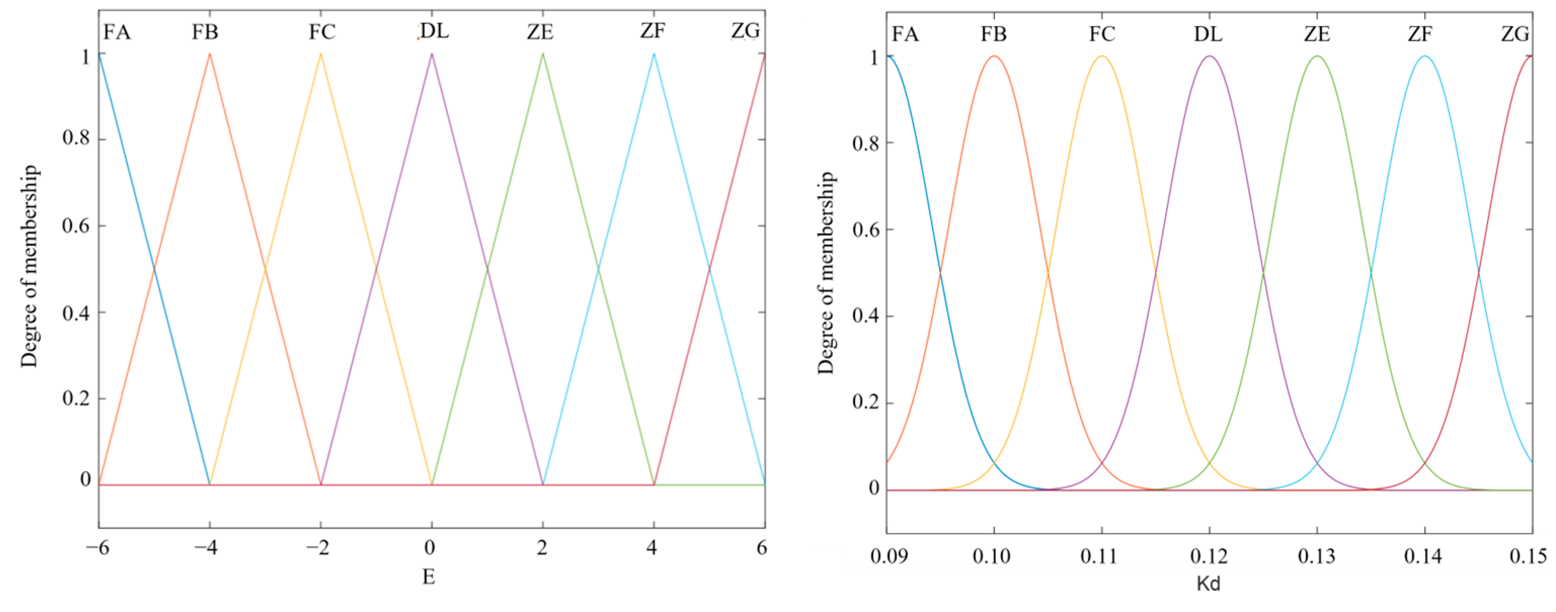
| Input and output variables | e | ec | ΔKp | ΔKi | ΔKd |
| Fuzzy language variable | E | EC | ΔKp | ΔKi | ΔKd |
| Fuzzy subset | [FA FB FC DL ZE ZF ZG] | ||||
| Fuzzy domain | [−6, 6] | [−6, 6] | [8.5, 9.1] | [0.2, 0.8] | [0.09, 0.15] |
| Kp/Ki/Kd | ec | ||||||
|---|---|---|---|---|---|---|---|
| e | FA | FB | FC | DL | ZE | ZF | ZG |
| Parameters | Connotation | Value | Unit |
|---|---|---|---|
| m | Armature mass | 0.5 | kg |
| K | Electromagnetic force conversion coefficient | 160.5 | m/s×A |
| Ky | Force conversion coefficient | 470 | N×m−1 |
| E | Armature assembly spring stiffness | 1 × 10⁴ | N×m−1 |
| R | Internal resistance of proportional valve electromagnet | 25 | Ω |
| L | Proportional valve electromagnet inductance | 6.6 × 10⁻² | H |
| Kq | Proportional valve flow gain is sufficient | 2.4 | - |
| Kce | Total flow pressure coefficient | 4.5 × 10⁻¹² | - |
| M | The load is converted to the equivalent mass on the piston | 150 | kg |
| β | Effective bulk modulus of elasticity port | 1 × 10⁹ | Pa |
| Vt | Total volume of hydraulic cylinder | 6 × 10⁻⁴ | m3 |
| Ap | Equivalent area of load flow | 3.75 × 10⁻³ | m2 |
Disclaimer/Publisher’s Note: The statements, opinions and data contained in all publications are solely those of the individual author(s) and contributor(s) and not of MDPI and/or the editor(s). MDPI and/or the editor(s) disclaim responsibility for any injury to people or property resulting from any ideas, methods, instructions or products referred to in the content. |
© 2025 by the authors. Licensee MDPI, Basel, Switzerland. This article is an open access article distributed under the terms and conditions of the Creative Commons Attribution (CC BY) license (https://creativecommons.org/licenses/by/4.0/).
Share and Cite
Li, M.; Chang, X.; Gu, Y.; Wang, P.; Shang, S. Design of Dynamic Deep Sowing System for Peanut Planter with Double-Loop Feedback Fuzzy PID Control. Agriculture 2025, 15, 808. https://doi.org/10.3390/agriculture15080808
Li M, Chang X, Gu Y, Wang P, Shang S. Design of Dynamic Deep Sowing System for Peanut Planter with Double-Loop Feedback Fuzzy PID Control. Agriculture. 2025; 15(8):808. https://doi.org/10.3390/agriculture15080808
Chicago/Turabian StyleLi, Moxian, Xueliang Chang, Yaqing Gu, Ping Wang, and Shuqi Shang. 2025. "Design of Dynamic Deep Sowing System for Peanut Planter with Double-Loop Feedback Fuzzy PID Control" Agriculture 15, no. 8: 808. https://doi.org/10.3390/agriculture15080808
APA StyleLi, M., Chang, X., Gu, Y., Wang, P., & Shang, S. (2025). Design of Dynamic Deep Sowing System for Peanut Planter with Double-Loop Feedback Fuzzy PID Control. Agriculture, 15(8), 808. https://doi.org/10.3390/agriculture15080808