Article

Adaptive Tracking and Cutting Control System for Tea Canopy: Design and Experimental Evaluation

1
College of Mechanical and Electrical Engineering, Gansu Agricultural University, Lanzhou 730070, China
2
Intelligent Equipment Research Center, Beijing Academy of Agriculture and Forestry Sciences, Beijing 100097, China
*
Author to whom correspondence should be addressed.
Agriculture 2025, 15(5), 557; https://doi.org/10.3390/agriculture15050557
Submission received: 17 February 2025 / Revised: 1 March 2025 / Accepted: 4 March 2025 / Published: 6 March 2025
(This article belongs to the Section Agricultural Technology)

Abstract

:
Combined with the characteristic that tea is generally planted in hilly and mountainous areas and considering the existing problems of harvesting with current tea pickers, such as the inability to adjust their posture in real time, poor adaptability to the terrain, insufficient stability, and large differences in the harvesting lengths of tea. To address these issues, an adaptive canopy-following cutting control system has been designed for self-propelled tea harvesters in this study. Specifically, we developed a height-following control algorithm for tea canopy tracking and an adaptive header tilt angle control algorithm based on incremental PID control. Field experiments demonstrated that when the vehicle speed was 0.4 m/s, the height tracking errors for three harvesting lengths (20 mm, 30 mm, and 40 mm) remained within ±5 mm, with correlation coefficients exceeding 0.99. When the height differences between the two sides of the tea ridge were 10 cm, 15 cm, and 20 cm, the maximum uphill roll angles were measured at 1.7°, 2.3°, and 3.0°, respectively, and the time taken for the harvester to return to a horizontal position was around 1.7 s. During downhill movement, the maximum roll angles of the harvester were 1.3°, 2.0°, and 2.6°, respectively, and the time for the harvester to return to a horizontal position was around 2.1 s, demonstrating significant correction effectiveness. Quality assessments revealed that at the 30 mm harvesting length specification, the integrity rate of tea harvesting exceeded 79%, while the missed harvesting rate was below 1.1%. This system effectively enhances harvesting stability and quality, offering novel insights for efficient, high-volume tea production.

1. Introduction

Tea, a pivotal beverage in contemporary global context, is extensively cultivated around the world. In China, the expanse of tea plantations has reached 3392.71 thousand hectares, accounting for more than 60% of the world’s production, ranking first in the world [1,2,3]. Among all the procedures within the tea production cycle, tea harvesting represents the most labor-intensive stage. Bulk tea, characterized by its large production, relatively low economic benefits, and less stringent demands for tea quality, has the established prerequisites for mechanized harvesting [4,5,6]. However, the majority of tea plantations in China are situated on hilly slopes and are characterized by dispersed and small-scale cultivation patterns. These plantations are marked by undulating tea canopies, height disparities between the two sides of tea ridges, and irregular inter-ridge pathways [7,8].
Currently, the equipment for bulk tea harvesting can be primarily classified into two categories: the ride-on type and the handheld type. Handheld devices, favored for their affordability and operational flexibility, are widely adopted [9,10,11,12,13,14]. Nevertheless, they suffer from drawbacks such as significant physical exertion requirements, relatively low operational efficiency, and challenges in ensuring the quality of harvested tea. By contrast, ride-on tea pickers demonstrate high harvesting efficiency and are capable of effectively addressing the peak periods of tea picking [15,16,17]. The tea pickers manufactured by Japanese companies such as Kawasaki and Ochiai embody the most advanced technological standards, equipped with the functionality to adjust the vehicle’s row spacing. Their inherent limitation lies in the inability to adjust the height of the harvester in real-time in accordance with the fluctuations of the tea canopy.
To tackle the problem of suboptimal quality during tea harvesting processes, the development of precise tea harvesting systems has been the subject of extensive research. The 4CJZ-1000 self-propelled tea picker, developed by Wang et al. [18], incorporates a side-mounted, reversible, tea harvesting apparatus on its vehicle body, thereby significantly enhancing its adaptability across diverse harvesting scenarios. An intelligent tea harvesting mechanism was engineered by Tang et al. [19], which employs RGB vision technology to gauge the distance to the tea surface. A dual-lead screw motor-controlled approach is implemented in this design to regulate the height and angular orientation of the cutting implement. The perception accuracy of RGB cameras is notably susceptible to environmental lighting conditions. A profiling-based tea picker was devised by Yan et al. [20], which utilizes a contact-type encoder to ascertain the height and roll angles of the tea canopy, serving as the fundamental basis for harvester profiling. Nevertheless, the detection precision of this apparatus is readily influenced by the density of tea plants. The automatic imitation and distributed control of a tea canopy harvester based on ultrasonic sensors was proposed by Chen et al. [21,22,23], relying on ultrasonic sensors. This device exhibits a complex structural configuration, and the post-harvest tea canopy condition is not conducive to subsequent pruning operations. A profiling distance estimation strategy for the harvester of a tea picker was proposed by Wu et al. [24], integrating 2D lidar-based ranging data with acceleration-related information. The major limitation of this approach lies in the exorbitant cost associated with high-precision lidar sensors. A tea-picking device featuring an adaptive angle harvester was developed by Yu et al. [25]. This device is equipped with functions such as slope detection-enabled adjustment of the harvester blade’s horizontal angle and utilization of the tea canopy’s reaction force for fine-tuning the cutting-in angle. Furthermore, in-depth research on the precise picking of premium-grade teas has been carried out [26,27,28,29,30,31,32,33,34]. Nevertheless, this precise picking technology is characterized by low production efficiency and is not suited for large-scale harvesting of bulk tea.
To address the aforementioned problems, this study presents a cutting pose control approach that enables the adaptive adjustment of the vehicle’s roll angle in accordance with the height fluctuations of the tea ridge canopy. Moreover, a control system tailored for adaptive tracking and cutting of the tea canopy in self-propelled tea pickers is engineered. By means of in-depth theoretical deliberations and comprehensive experimental investigations, the fabrication of a prototype and the optimization of its parameters are successfully carried out. The overarching objective is to ensure a consistent tea harvesting length, boost the integrity rate of harvested tea, and minimize damage to the tea canopy. This study is expected to provide a foundation for the development of high-quality harvesting technologies for bulk tea.

2. Materials and Methods

2.1. Composition of Tea Harvesting Mechanism

As shown in Figure 1, the tea picker comprises three integral components: an autonomous vehicle, a control system, and a harvester unit. The autonomous vehicle, a gantry-style electric-drive crawler vehicle, is the result of independent research and design efforts by our team. It is equipped with advanced algorithms for precisely tracking tea ridges. A comprehensive set of its technical parameters is provided in Table 1. The harvester employs a flat-bladed reciprocating harvester mechanism (Kawasaki, Hangzhou, China). The key parameters that define its operational characteristics are presented in Table 2. The control system effectively integrates the autonomous vehicle and the tea harvester, enabling the harvester to perform contour-adaptive harvesting based on tea canopy height variations and adjust its roll angle during operation, thereby enhancing the quality of tea harvesting.

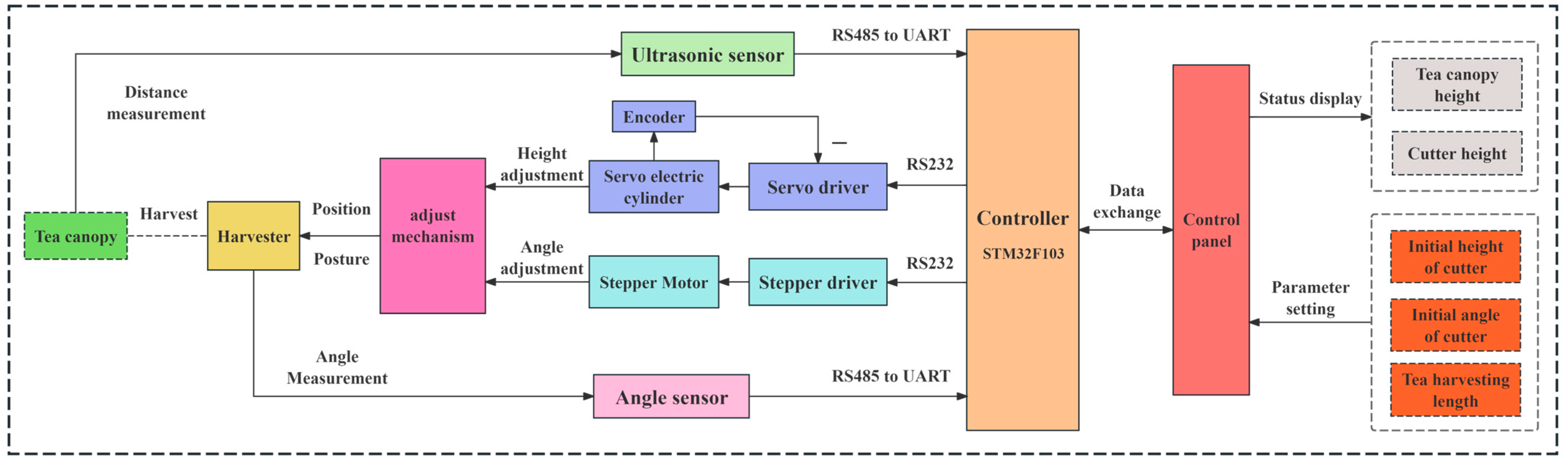
2.2. Design of the Control System

The control system is the core component of the tea picker. Utilizing an unmanned vehicle as the carrier platform, it regulates the height and roll angle of the harvesting device. During operation, the vehicle travels at a constant speed while the control system identifies environmental variables. Through analysis and calculations, it controls the harvesting device to perform corresponding operations. An ultrasonic sensor detects the tea canopy height, which serves as the basis for adjusting the electric cylinder’s extension/retraction amount to regulate the harvesting height. Meanwhile, an angle sensor monitors the tilt angle of the harvesting device, providing data to determine the rotation amount of the gear motor for angle correction.

2.2.1. Structural Design

The fluctuations in the height of the tea canopy and the elevation disparities on either side of the tea ridge are pivotal factors that significantly impact the quality of tea harvested by machinery. In this study, with the primary objective of achieving real-time modulation of the height and roll angle of the harvester, a meticulously designed control system was developed, as depicted in Figure 1.
This control system encompasses several core components, including a controller responsible for overall operation management, a height adjustment mechanism dedicated to precisely adapting to the vertical variations of the tea canopy, a roll angle correction mechanism aimed at maintaining the optimal orientation of the harvester, an ultrasonic sensor and angle sensor proficient in sensing relevant environmental parameters, and a control panel facilitating user–system interaction.
The controller, with the STM32F103RET6 microcontroller (ST, Paris, France) unit at its core, undertakes a series of crucial functions. It is responsible for precisely acquiring real-time data from various sensors, meticulously generating control instructions that govern the position and attitude (pose) of the harvester, and continuously monitoring the operational states of all regulation devices. The height adjustment mechanism is segmented into two distinct functional components: the fixed height adjustment module and the track adjustment module. The fixed height adjustment segment is constructed by integrating a sturdy machine frame and an electric cylinder frame. This configuration allows for an adjustment within the range of 0 to 80 cm, with incremental adjustments available at intervals of 5 cm. On the other hand, the track adjustment module consists of a high-performance YC60-T05-200 servo electric cylinder (Xiucang, Shenzhen, China) and a precision-engineered guide rail. It offers an adjustment range of ±100 mm, enabling a rapid response with a maximum operating speed of 1 m/s. The roll angle correction mechanism is principally composed of a reduction motor (ZD, Ningbo, China) and a rotation angle-limiting mechanism. The shaft of the reduction motor is rigidly connected to the installation frame of the harvester. The adjustment range of the roll angle is precisely set to ±15°, and the mechanism is designed to operate with a maximum angular velocity of 20°/s. Additionally, a safeguard mechanism is implemented to prevent over-rotation by setting an upper limit for the rotation angle. The detection module is equipped with two KS108 ultrasonic ranging sensors (OSENON, Shenzhen, China) and two SINDT angle sensors (WIT Motion, Shenzhen, China). These sensors are strategically deployed to accurately sense the height of the tea canopy and the roll angle of the vehicle body. The two ultrasonic sensors, spaced 60 cm apart, are installed in parallel, positioned 120 cm above the ground surface and precisely 30 cm in front of the harvester. The two angle sensors are horizontally mounted on the cross-beam of the vehicle body and the harvester, respectively. In their initial calibration state, the Y-axis angles of the angle sensors are set to 0°. The resolution accuracy of the ultrasonic sensor is 3 mm, and the resolution accuracy of the angle sensor is 0.01 degrees. The control panel serves as the interface for visual data exchange, enabling seamless interaction between the operator and the control host.

2.2.2. Control Principle

The position and attitude (pose) control of the harvester encompasses two primary objectives: height modulation and roll angle regulation. During the operation of the control system, the controller assimilates multiple data inputs. These include the initial height of the harvester and the designated tea harvesting length, which are configured via the control panel, along with the height of the tea canopy, the roll angle of the vehicle body, and the roll angle of the harvester, all of which are sensed by the corresponding sensors. Upon receipt, the acquired data undergo a series of processing steps. Subsequently, through calculations and decision-making processes within the core program, commands are dispatched to the actuator controllers. These commands are designed to precisely govern the operations of the electric cylinders and motors, thereby ensuring the accurate conveyance of the harvester to its intended operational position. Simultaneously, the real-time operational status of the system is continuously relayed to the control panel, as depicted in Figure 2.
The operational principle of the control system is graphically depicted in Figure 3. In the context of tea harvesting activities, the height adjustment mission necessitates the meticulous regulation of the vertical displacement of the harvester, ensuring that it closely follows the elevation changes of the tea canopy. Conversely, the roll angle adjustment objective is centered around preserving the horizontal alignment of the harvester. The vehicle roll angle (VRA), induced by the height differential H between the two lateral edges of the tea ridge, is symbolically represented by ψ. The angular deviation between the horizontal plane and the surface of the harvester, which is the harvester roll angle (HRA), is denoted as θ, signifying the angular correction required for the harvester.
To reduce the impact of terrain disturbances on the calculation outcomes, relative elevation is employed. In accordance with the spatial structural attributes of the regulation and control mechanism, the plane encompassing the transmitting head of the ultrasonic sensor is designated as the system reference plane. Here, ∆l embodies the requisite extension and retraction magnitude of the electric cylinder. l0 represents the mean value of the distances measured by the two ultrasonic sensors to the tea canopy. l1 denotes the distance from the central axis of the motor shaft to the reference plane when the electric cylinder is in its initial configuration. l2 represents the distance between the center of the rotating shaft and the cutter surface of the harvester. h symbolizes the predefined height for tea harvesting. θM represents the angular rotation required of the motor, and i denotes the transmission ratio of the reduction gear. The interrelationships among these variable parameters are explicitly elucidated in Equation (1).
Δ l = l 0 l 1 l 2 h cos ψ θ M = i × θ

2.3. Harvester Height Tracking Control Algorithm

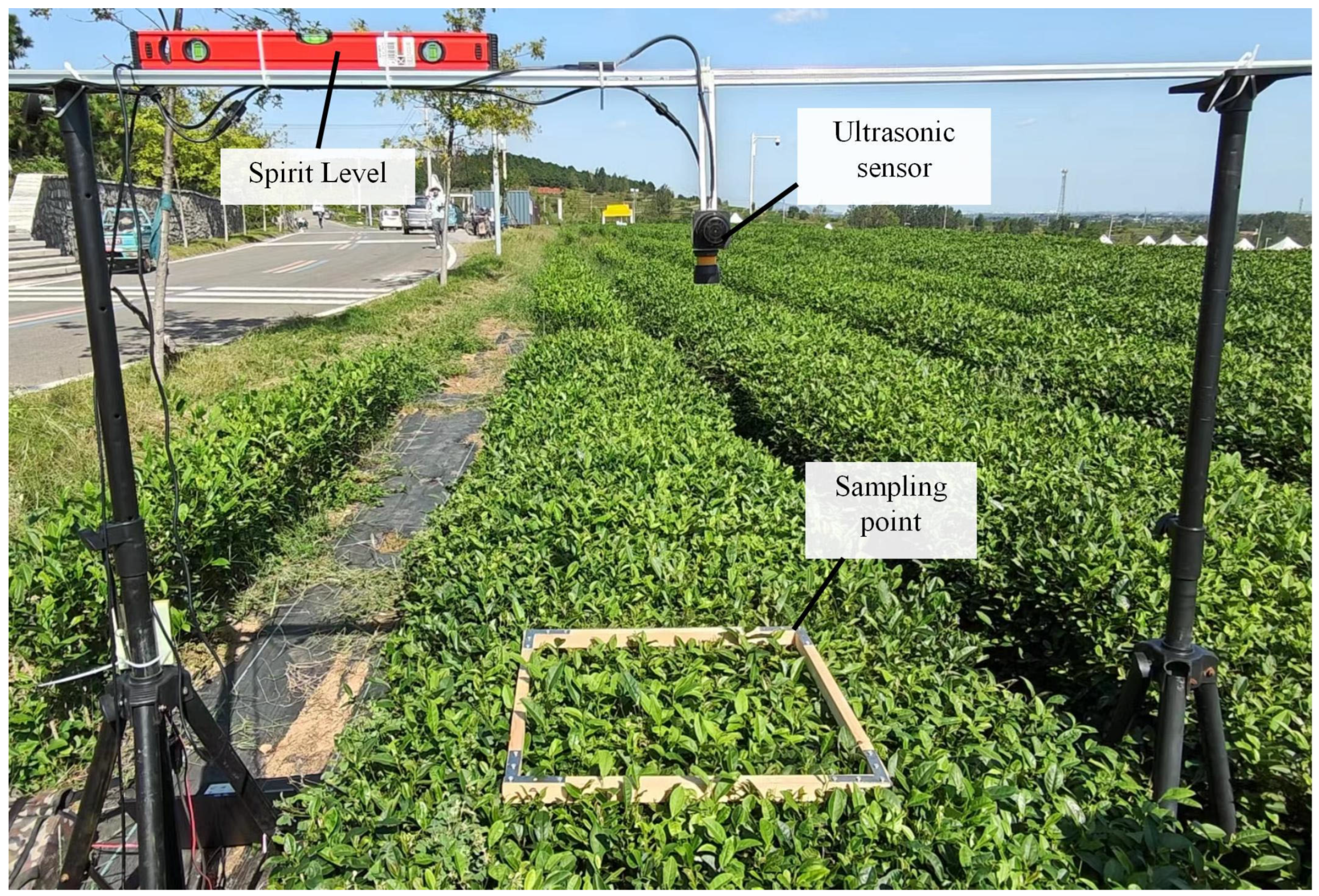
2.3.1. Acquisition of Tea Canopy Height

In the height control system of the harvester, ultrasonic sensors are employed to determine the height of the tea canopy. Nevertheless, ultrasonic ranging sensors inherently acquire relative distance data corresponding to the uppermost point within their detection domain. When local discontinuities exist in the tea canopy or when tea branches extend beyond the regular canopy surface, measurement inaccuracies are likely to ensue. To mitigate these potential errors, strategies including an increase in sampling frequency and the elimination of noise-affected data points are implemented to accurately obtain the height information of the tea canopy. The sampling period of the ultrasonic sensors is precisely configured to 50 ms. For each data acquisition event, the distance values ξ L and ξ R from the left and right sides are collected and then averaged to yield the mean distance ξ ¯ . All of the data are arranged in column ξ n ¯ in chronological order to obtain the information curve of the tea canopy height. The recursive average filtering method is adopted to reduce noise. A buffer with a fixed length equivalent to five sets of average height values ξ ¯ is set up. The newly collected data are added to the end of the queue, and the data at the head of the queue are discarded simultaneously to ensure that the five data points in the queue are all the latest. Then, the arithmetic meaning ξ of these five data points in the queue is calculated and taken as the valid value. The associated formula is presented as Equation (2):
ξ t = 1 t 1 t ξ ¯ t , t < 5 ξ t = ξ ¯ t - 2 + ξ ¯ t - 1 + ξ ¯ t + ξ ¯ t + 1 + ξ ¯ t + 2 5 , t 5
where t symbolizes the current operational instant, while ξ t represents the detected distance corresponding to the time. The value of ξ t , following recursive average filtering, is adopted as the effective detection distance for the height at the specific point of the tea canopy. Thereby, the obtained tea canopy height functions as the reference line for the harvester to track, as depicted in Figure 4. Through numerous experimental trials, it was conclusively verified that the error associated with the measurement of the tea canopy height was effectively confined within 3%. As a result, the findings derived from these tests can be considered a dependable foundation for the precise control of the harvesting height tracking process.

2.3.2. Control Method for Harvester with Matching Lifting Speed

In the context of tea harvesting, the length of the harvested tea is determined by the height difference between the tea canopy and the cutting plane. Due to the uneven growth of tea, the operating speed of the vehicle body and the extension speed of the electric cylinder are crucial factors determining the accuracy of height tracking and work efficiency. When the operating speed V of the vehicle is set to a constant value, the extension speed v of the electric cylinder changes dynamically according to the target extension amount.
As illustrated in Figure 5, within the context of the target path, S1 and S2 signify an arbitrary pair of adjacent target operational points. The process of height tracking entails precisely controlling the harvester to successively reach all target operational points as the vehicle progresses. In the operational process, the motion of the harvester from point S1 to point S2 is designated as an operational segment. Specifically, the horizontal displacement between S1 and S2 is termed the operational spacing, denoted by ∆s′, while the vertical elevation difference between these two points is referred to as the operational height spacing, denoted by ∆h′. The degree of undulation of the target path is quantified by the slope k between any two adjacent operational points, which is calculated as the quotient of ∆h′ divided by ∆s′, and a larger value of the parameter k indicates a more significant fluctuation in the height of the tea canopy layer. The temporal duration for the harvester to traverse between these two operational points is defined as the operational cycle, symbolized by T.
As the quantity of selected operational points increases, the harvesting trajectory progressively approximates the target path. In other words, a reduction in the value of ∆s′ corresponds to an enhancement in the tracking accuracy. The magnitude of ∆s′ is jointly determined by T and V. Specifically, T is constrained by the minimum stable operational cycle of the electric cylinder, while V is subject to the influence of the slope k of the target path and the adjustment speed ratio λ.
The servo electric cylinder is required not only to precisely execute the height variation ∆h′ within any given operational segment but also to operate in a smooth and continuous manner, devoid of any pauses, during the transition through each operational point. Through extensive experimental trials, the adjustment cycle of the electric cylinder was calibrated to T = 0.2 s.
The capacity of the height tracking system to adapt to the undulations of the target path is intricately linked to the adjustment speed ratio λ, which is defined as the quotient of the average extension speed v of the electric cylinder and the velocity V of the vehicle. The greater the value of λ, the more sensitive the height adjustment of the harvester becomes. To guarantee the surplus of the regulated volume, the value of k must satisfy the relationship specified in Equation (3):
k = λ λ MAX
Based on the degree of fluctuation of the target path, with k ≤ 2.5, the maximum running speed of the electric cylinder is given as vMAX = 1 m/s. It is calculated that the vehicle speed V ≤ 0.4 m/s. To ensure the operation efficiency, the vehicle speed V is taken as 0.4 m/s. Therefore, suppose the operation spacing is denoted as ∆S′, and the corresponding calculation formula is presented as follows:
Δ S = V × T
It is obtained that ∆S′ = 80 mm.
To address the need for different height increments to be adjusted in each operational segment, with the aim of achieving stable and accurate control of the electric cylinder, it is essential to elucidate the relationship between the adjustment velocity of the electric cylinder and its corresponding height increment. The mounting distance between the ultrasonic sensor and the harvester remains constant, and a fixed time lag exists between the ultrasonic detection process and the regulation of the harvester. The magnitude of the height adjustment for the harvester is defined as the difference between the height at the present moment and that of the subsequent target point. During the operational process, the controller retrieves the height hn of the position of the harvester at time tn, computes the height hn+1 of the target position at time tn+1, and determines the adjustment height increment ∆hn. Consequently, the following relationship holds:
Δ h n = h n + 1 h n
Over the entire operational course, the servo electric cylinder executes variable-speed motions. Ensuring the continuity and smoothness of the height adjustment necessitates that the servo electric cylinder operates at a relatively high speed and undergoes velocity changes in a stable manner. The speed control mode is the most suitable approach for the servo electric cylinder to satisfy these requirements. In the speed control mode, the operational progression can be partitioned into three distinct phases: the acceleration phase, the steady-state phase, and the deceleration phase. When the servo electric cylinder experiences a velocity transition, a velocity step occurs. Significantly, a smaller adjustment distance corresponds to a negligible velocity abrupt change, thereby exerting less influence on the overall adjustment cycle. Prolonging the buffer time is an efficacious strategy to mitigate the velocity step. In the speed control mode, both the acceleration time and the deceleration time are precisely configured to T1 = 0.1 s. Both the acceleration and deceleration phases are characterized by uniformly accelerated motion. The duration of constant-speed operation is set as T2 = 0.1 s. During continuous operation, within a single cycle, the electric cylinder encompasses only one variable-speed segment and one constant-speed segment. To ensure the smooth progression of the harvester to the subsequent target point, the ideal velocity that the electric cylinder should attain is given by:
v n + 1 = 2 Δ h n v n × T 2 T 1 + 2 T 2
where vn+1 represents the target operating speed of the electric cylinder, while vn represents the current operating speed of the electric cylinder.

2.4. Adaptive Control Algorithm for the Roll Angle of the Harvester

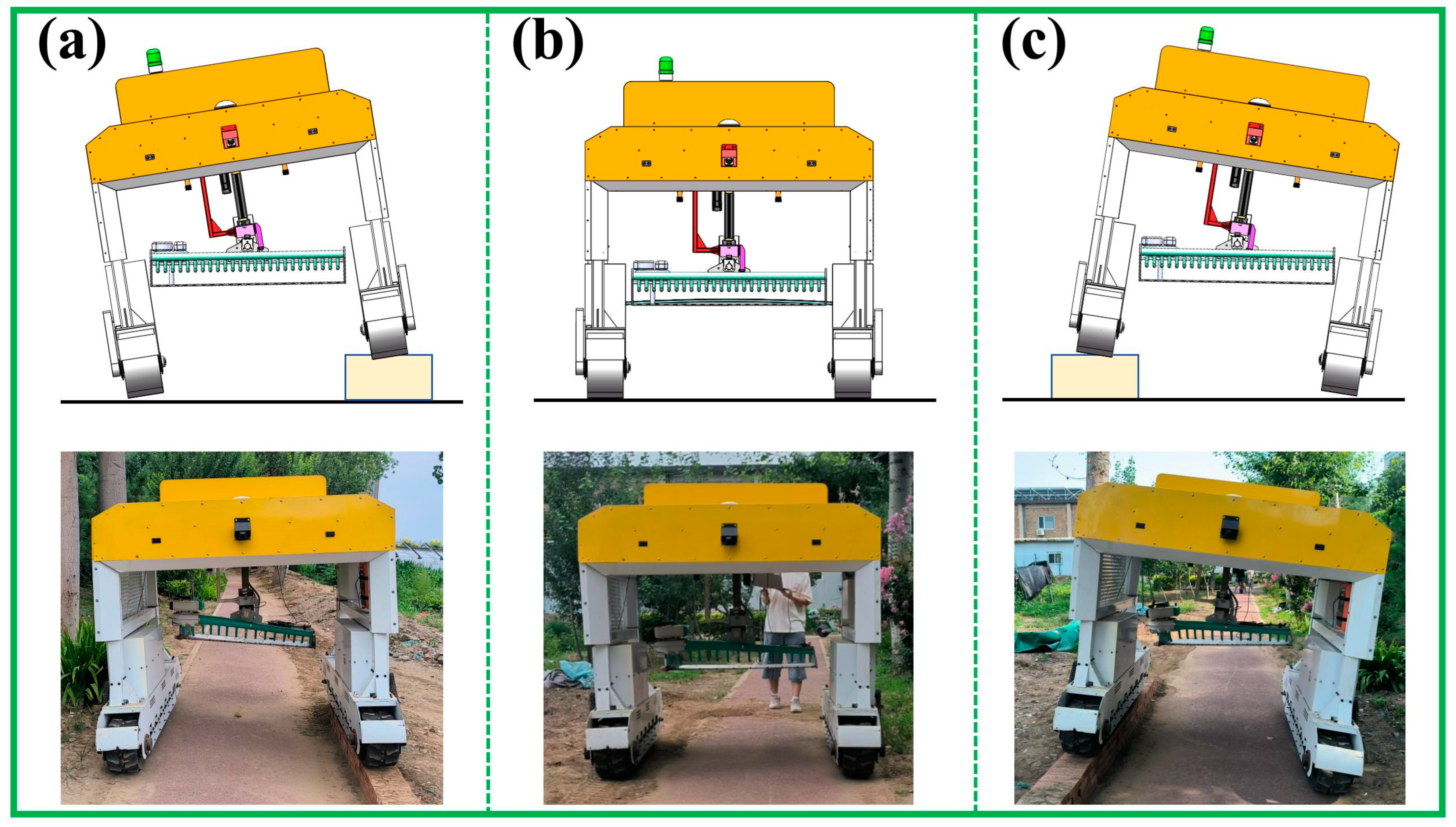
2.4.1. Methods for Correcting the Roll Angle of Harvesters

The roll angle of the harvester is corrected to eliminate the impact of the height difference between the roads on both sides of the tea ridge and the vehicle body vibrations on the quality of tea harvesting. A reduction motor is needed to control the horizontal state of the cutter surface. In the roll angle correction mechanism, the harvester body is connected to the rotating shaft of the reduction motor. Due to the characteristics of the reduction motor, its response is lagged. When the vehicle body rolls, the harvester tilts with the vehicle body, changing the horizontal state of the reduction motor. When the motor torque remains unchanged, the harvester will rotate until the torque is balanced again, and the harvester may not be horizontal. Therefore, the motor torque needs to be adjusted according to the change of the harvester torque. In order to output a constant and accurate torque, the reduction motor adopts the torque mode in this process.
As illustrated in Figure 6, the center of the rotating shaft is positioned 250 mm directly above the cutter surface of the harvester. Owing to the structural characteristics of the harvester, the gravitational force G exerts a certain moment M on the rotating shaft. Consequently, the reduction motor is required to proactively supply a reverse torque T to ensure the horizontal alignment of the cutter surface. Under the condition that the roll angle of the vehicle body is zero and the cutter surface is level, the generated torque equation is established as follows:
M 0 = G × L × cos α 0
where M0 denotes the torque generated when the cutting surface of the harvester is maintained in a horizontal state. G = mg, where m represents the mass of the harvester, which is 22 kg, and g represents the acceleration due to gravity, take g = 9.81 N/m2. L represents the distance between the center of the rotating shaft and the point of application of the gravitational force, and L = 450 mm. α0 represents the deviation angle of the center of gravity, specifically, the angle between the line connecting the center of gravity and the center of rotation and the horizontal line, and α0 = 27°.
It is deduced that the balanced relationship of the harvester roll angle correction system is as follows:
M = G × L × cos ( α 0 + θ )
where M represents the torque generated by the harvester, in N/m.
Formulate the kinematic equation. The torque T of the reduction motor is required to counterbalance the gravitational moment M of the harvester and the moment related to the moment of inertia MI. The kinematic equation is presented as shown in Formula (9).
T ( t ) = M ( t ) + M I ( t ) = G × L × cos ( α 0 + θ ( t ) ) + I × d 2 θ d t 2
where I denotes the moment of inertia, in units of kg·m2, where I = mL2; d 2 θ d t 2 stands for the acceleration of the harvester.
When the center of gravity deviation angle is greater than the maximum allowable roll angle of the machine, that is, α0θMAX, the torque decreases as the roll angle of the harvester increases. The relationship between θ and M is as follows: when −15° < θ ≤ 0°, M > M0, T gradually decreases until T0, and the harvester rotates counter-clockwise until it is horizontal; when 0° < θ ≤ 15°, M < M0, T gradually increases until T0, and the harvester rotates clockwise until it is horizontal. The reduction motor provides a counter-clockwise torque, as shown in Figure 6. In addition, the horizontal state of the cutter surface is disturbed by the reaction force of the tea plants. The reduction motor needs to provide a torque to stably maintain the horizontal state of the cutter surface. To avoid damage to other components of the whole machine caused by excessive torque, a protection threshold of 300 N/m is set.

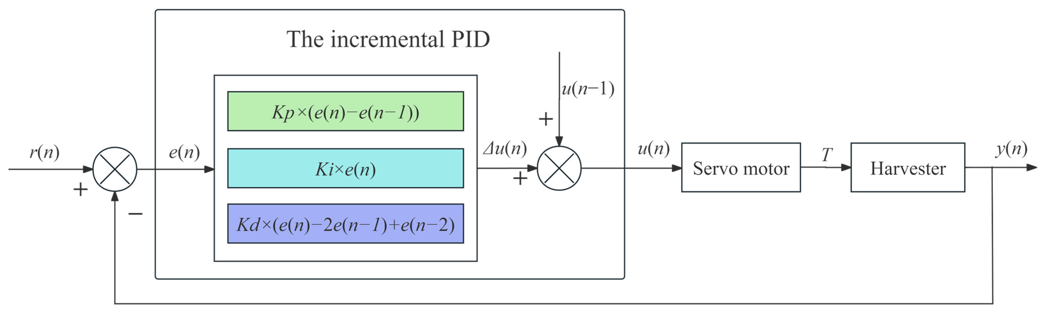
2.4.2. The Adaptive PID Control Algorithm for Roll Angle

The adaptive correction of the roll angle is based on controlling the reduction motor to correct the roll angle of the harvester in real time and keep it horizontal. An angle sensor is directly installed on the harvester body, which can provide the original tilt angle signal and feedback the executed angle signal, forming a closed loop control to ensure real time performance and accuracy. When the sensor detects a deviation angle θ, the reduction motor rotates in the reverse direction until the cutter surface of the harvester is horizontal. It is our expectation that the angular correction and compensation process can be accomplished within an extremely brief time span ∆t. This ensures that the displacement of the vehicle during the corresponding time period is so minuscule that it can be regarded as negligible, thereby guaranteeing the efficacy of the system. In this context, the system response time is disregarded, and the relevant equation is presented as Equation (10):
Δ t = θ ϖ S = v Δ t
As can be inferred from the aforementioned equation, the influencing factor of the time interval ∆t hinges upon the roll angle θ and the average angular velocity ω of the geared-down motor. Meanwhile, the displacement S of the vehicle is dictated by the travel speed v and time ∆t. Consequently, ω emerges as a pivotal determinant for the system’s real-time responsiveness. The ultimate aim is to effectuate the adjustment of the harvester’s angle within an infinitesimally short vehicle body displacement. In this study, the incremental PID control [35] algorithm is adopted for the roll angle correction control of the harvester. It forms a deviation e(n) = r(n) − y(n) based on the given ideal roll angle value r(n) = 0 of the harvester and the actual roll angle value y(n) of the harvester. u(n) is the control signal for the torque of the reduction motor in the roll correction system. Figure 7 illustrates the structure diagram of the harvester roll angle controlled by PID.
The discrete expression of position PID is as follows:
u ( n ) = K p e ( n ) + T T i i = 0 n e ( i ) + T d T e ( n ) e ( n 1 )
where T represents the sampling period, Ti denotes the integral time constant, and Td stands for the derivative time constant. And the simplified form is as follows:
u ( n ) = K P e ( n ) + K i i = 0 n e ( i ) + K d e ( n ) e ( n 1 )
where Kp is the proportional coefficient, Ki is the integral coefficient, and Kd is the derivative coefficient.
Δ u ( n ) = u ( n ) u ( n 1 )
The following equations can be obtained:
Δ u ( n ) = K P e ( n ) e ( n 1 ) + K i e ( n ) + K d e ( n ) 2 e ( n 1 ) + e ( n 2 )
where, the three coefficients Kp, Ki, and Kd are crucial for ensuring that the harvester returns to a horizontal state, controlling the overshoot, and maintaining the system’s stability. It determines crucial aspects such as the response speed and control precision of the adjustment for the harvester’s roll angle. In view of this, it is necessary for us to derive the transfer function G(s) by solving the kinematic equation. By conducting a Laplace transform on Equation (9), we can obtain the equation as follows:
G ( s ) = 1 m L 2 s 2 G L sin ( α 0 )
The calculation of the steady-state gain is as follows:
K = 1 G L sin ( α 0 )
The steps of the parameter debugging process are as follows. Firstly, we needed to solve the initial theoretical value of Kp = 1/K. Referring to the theoretical value, we set a relatively small value for Kp and set Ti and Td to 0. Then, we observed the system response and gradually increased Kp, until the system exhibited continuous oscillations. We recorded the value of Kp (denoted as Kc) and the oscillation period Tu at this time, then we calculated the initial parameters according to the Ziegler–Nichols’s method: Kp = 0.6 × Kc, Ti = 0.5 × Tu, Td = 0.125 × Tu. After that, we made fine adjustments based on these initial parameters. After multiple trials and parameter adjustments, the final values of the three coefficients Kp, Ki, and Kd were determined as follows: Kp = 50, Ki = 2, and Kd = 1.
The equations of the deflection angle correction control system are as follows:
y ( n + 1 ) = ϕ ( y ( n ) , u ( n ) )
where ϕ ( ) is the control function of the deflection angle correction system.
To prevent the system from jittering, the maximum allowable deviation value of e(n) is ±10°. If the error between two detections exceeds the maximum allowable deviation, the calculation shall be based on the maximum deviation.

2.5. Experiment

To guarantee the detection precision of the ultrasonic sensors, the discrepancies between the measured values and the actual values of the ultrasonic sensors were determined. An experimental platform, as illustrated in Figure 8, was erected in the tea plantation for calibrating the measurement errors of the ultrasonic sensors. This platform enabled the free adjustment of the distance between the detection plane of the ultrasonic sensor and the tea canopy layer. Moreover, a spirit level was employed to ensure that the detection direction of the ultrasonic sensor was precisely aligned with the tea canopy layer.
For the sake of ensuring the accuracy of the calibration results, ten distinct sampling points were chosen during the calibration. At each sampling point, five sets of different distances were configured, respectively. Subsequently, the detection distances of the ultrasonic sensor were recorded. The error values of the detection distances at the same height across the ten sampling points were computed, and the maximum error value was noted. Thereby, the detection errors of the ultrasonic sensors were obtained, as presented in Table 3.
To verify the various performance indicators of this system, the experiment was conducted in a standard tea plantation in Jufeng town, Rizhao city, on 13 September 2023. This tea plantation features a hilly and gentle slope terrain, and the tea ridges are densely planted along the contour lines. The average width of the tea ridges is 100 cm, the average height is 55 cm, and the distance between ridges is 130 cm. The maximum slope of the tea plantation is 15°, and there is a height difference of 20 cm between the roads on both sides of the largest tea ridge.

2.5.1. Verification of Height Tracking Stability

In the tea plantation, a tea ridge with a flat terrain, a length of 20 m, and had not been picked or pruned for three or four weeks was selected. We then marked the middle 10 m as the test section. After that, we set the operating speed at 0.4 m/s, and tested in three harvesting lengths at 20 mm, 30 mm, and 40 mm, respectively. The experiment started 5 m before the marked section and ended 5 m after the marked section. The target trajectory, operating trajectory, and operating time of the test section were recorded, respectively. Each group of experiments was repeated three times, and the average value was taken. During the experiment, in order to avoid damaging the tea canopy, the height of the harvester was increased by 30 cm, and it was not started.
We conducted a comparative analysis of the differences between the target cutting trajectories and the actual cutting trajectories under different set lengths, observed the distribution of the harvesting length errors, and used the root mean square error (RMSE), Pearson correlation coefficient (PCC), and the concentrated interval of errors as evaluation indicators to assess the stability and accuracy of the cutting height tracking the height of the tea ridges.

2.5.2. Verification of Roll Angle Correction Accuracy

The roll angle correction stability test was conducted to verify the compensation and correction effect on the roll angle of the harvester. The test factor was the different height differences between the roads on both sides of the tea ridge, and the evaluation indicators were the maximum deflection angle of the harvester and the leveling-off time. To simulate the height disparity between the two sides of the ground flanking the tea ridge, we constructed single-side bridges. Firstly, a section of horizontal roadway was selected, upon which three sets of single-side bridges were erected. These bridges featured a height H of 10 cm, 15 cm, and 20 cm, respectively, each stretching 3 m in length and 15 cm in width. A 5 m control zone was reserved both in front of and behind each set of single-side bridges. The speed of the vehicle was set at 0.4 m/s. Meanwhile, with the aim of validating the influence of the center of gravity offset of the harvester on horizontal stability, as depicted in Figure 9, during the test, the left and right tracks were made to traverse the three sets of single-side bridges independently. The angle data of both the vehicle body and the harvester were recorded when ascending and descending slopes. Each group of tests was repeated five times, and the average value was then obtained. By conducting a comparative analysis of the relationship between the alteration in the angle of the vehicle body and the roll angle of the harvester, we evaluated the stability of the roll angle correction.

2.5.3. Verification of Harvesting Quality Evaluation

The harvesting quality of tea directly reflects the performance of the entire control system. As shown in Figure 10, this experiment was conducted under two scenarios differentiated by the presence or absence of height discrepancies on the road surfaces flanking the tea ridges. Specifically, one tea ridge with an indistinct height variation was chosen from which three sampling segments, each measuring 5 m in length, were extracted. Meanwhile, another tea ridge featuring a more pronounced height difference was selected, and a single sampling segment of 5 m length was obtained therefrom. During the experiment, the speed of the prototype was set at 0.4 m/s, and the harvesting length was set at 30 mm. The tea in each sampling section was collected and counted separately. The harvesting quality of the tea was evaluated by measuring the integrity rate, the missed harvesting rate, and the length distribution of the harvested tea, with reference to the industry standard NY/T 2614-2014 [36].
The steps for determining the tea integrity rate are as follows. Mix the collected fresh tea samples evenly to form a bulk sample. Extract an analytical sample weighing not less than 100 g from it, measure the mass of intact tea, and calculate according to Equation (18). Repeat the process three times and take the average value.
P = m M 1 × 100 %
where P represents the integrity rate of tea; m represents the mass of intact tea, in g; and M1 represents the total mass of the analytical sample, in g.
The steps for determining the tea missed harvesting rate are as follows. Manually pick the tea that was missed in the sampling section, then weigh it. Calculate according to Formula (19). Repeat the process three times and take the average value.
Q = N N + M × 100 %
where Q represents the missed harvesting rate of tea; N represents the mass of the tea manually re-harvested within the sampling section; and M represents the total mass of the sample in each sampling section.

3. Results and Discussion

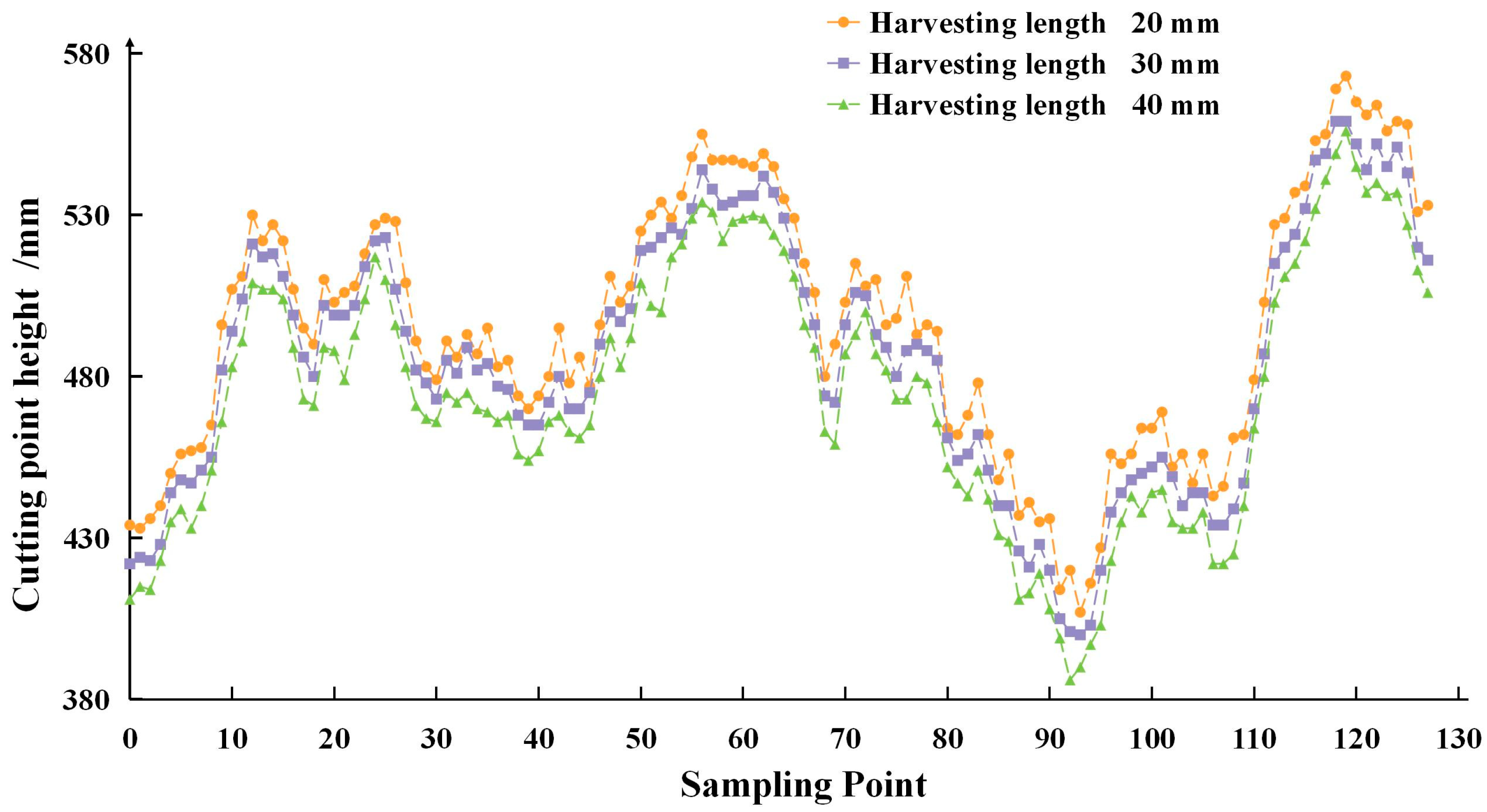
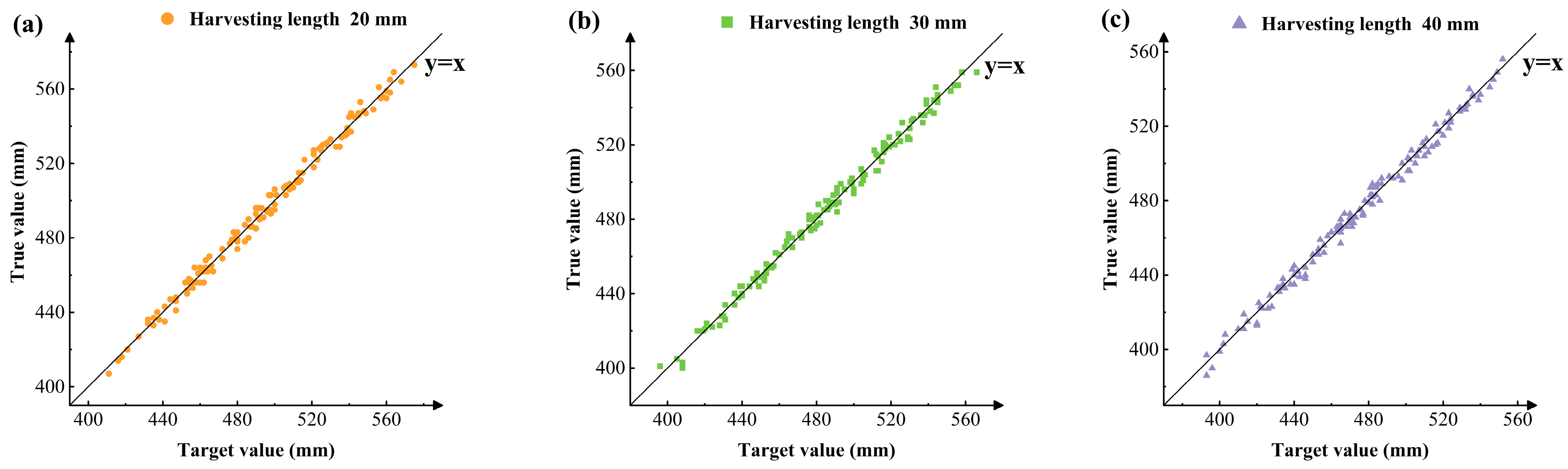
3.1. Height Tracking Stability

After performing coordinate transformation on the extracted data of the telescopic distance of the servo electric cylinder, we obtained the absolute height of the operation trajectories for different harvesting lengths, as shown in Figure 11. It can be directly observed from the figure that, under different harvesting lengths, the changing trends of the operation trajectories are highly similar. Although there are differences in the height of each trajectory, this indicates that the height tracking of the operation trajectories is stable for different harvesting lengths.
Figure 12 shows the height tracking accuracy of cutting for different harvesting lengths. It can be visually observed from the figure that the actual values for the three harvesting lengths of 20 mm, 30 mm, and 40 mm are all concentrated near the straight line y = x. In order to verify whether the cutting heights under different harvesting lengths had statistical significance, an analysis of variance was conducted. The results showed that there were significant differences in cutting heights under different harvesting lengths (p = 0.0001 < 0.05). Further calculations showed that the Pearson correlation coefficients (PCC) between the actual and target height trajectories under the three harvesting lengths were 0.9914, 0.9958, and 0.9959, respectively. The root mean square errors (RMSE) were 3.45 mm, 3.59 mm, and 3.62 mm, and the mean absolute errors (MAE) were 3.17 mm, 3.01 mm, and 2.97 mm. The height tracking error under the three harvesting lengths was mainly concentrated within the range of ±5 mm. The relevant parameters are shown in Table 4. This indicated that the height-tracking performance under the three different harvesting lengths was good, with a small average error and error fluctuation, meeting the design requirements.

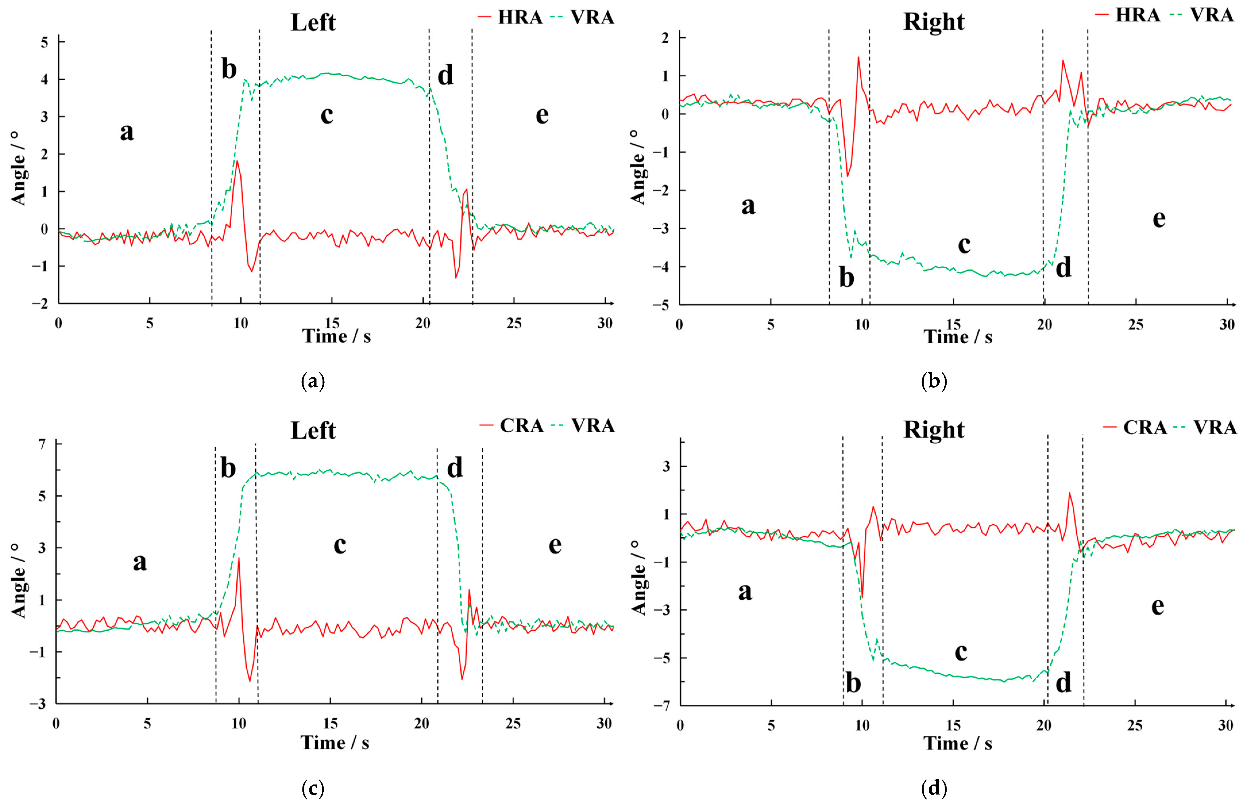
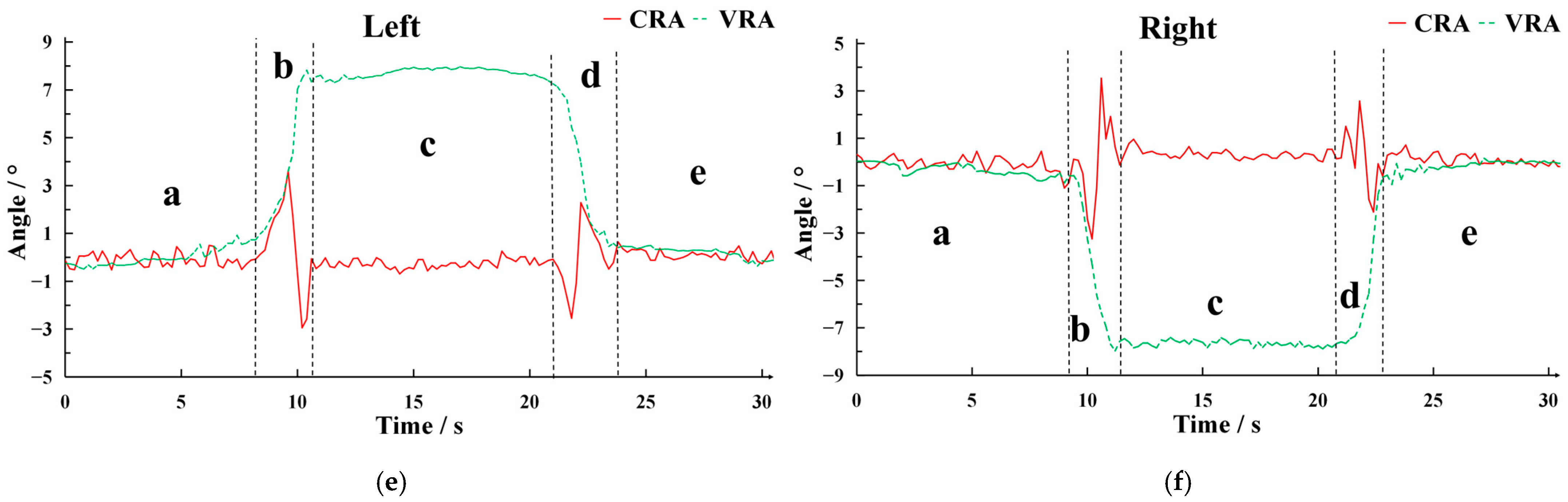
3.2. Correction Performance of the Harvester Roll Angle

The test results of the harvester roll angle correction stability are shown in Figure 13. As seen from the figure, the changes in the harvester roll angle across different test groups were highly consistent, with small fluctuation errors. The time for the roll angle of the vehicle body to change until it stabilized was nearly the same as the correction response time of the harvester. Details of the maximum inclination angles and re-leveling times for different H values are listed in Table 5. When the height was 10 cm, 15 cm, and 20 cm, the maximum uphill inclination angles of the harvester were 1.7°, 2.6°, and 3.6° respectively, and the maximum downhill inclination angles were 1.4°, 2.0°, and 2.6°. The uphill re-leveling time was 1.6 to 1.8 s, and the downhill re-leveling time was 2.0 to 2.2 s. The experimental findings indicated that the harvester roll angle correction was hardly affected by the lateral tilt of the vehicle body. A sudden change in height caused an instantaneous maximum deviation in the harvester roll angle, which was quickly adjusted to the horizontal. This showed that the sudden changes in the harvester roll angle were mainly due to the mechanical properties of the correction mechanism. Under the same height, the maximum roll angle uphill was slightly larger than downhill, but the average re-leveling time was hardly affected by height or the tilt direction of the vehicle body. This meant that the adjustment time of the inclination angle correction system was stable. Also, under the same height, the uphill re-leveling time was slightly shorter than downhill. The analysis showed that the installation position of the harvester on the vehicle body caused differences. In conclusion, the harvester had good horizontal control stability and its control accuracy met the design requirements.
In Figure 13, segment a designates the pre-stable operational phase, segment b typifies the uphill adjustment phase, segment c symbolizes the stable operational stage atop the slope, segment d epitomizes the downhill adjustment phase, and segment e connotes the post-stable operational phase, each segment corresponds to the time required for that phase. The green dotted line delineates the roll angle of the vehicle body, whereas the red solid line illustrates the roll angle of the harvester. It can be discerned from the figure that the line segments of segments a and e coincided under disparate roll angle conditions of the vehicle body. This indicated that on a horizontal roadway surface, neither the vehicle body nor the harvester underwent any angular deflection, both sustaining at 0°, with the cutter surface of the harvester in a level state. During segments b and d, corresponding respectively to the vehicle body ascending and descending the slope, when the roll angle of the vehicle body fluctuated, the roll angle of the harvester underwent an abrupt variation, engendering an instantaneous maximum roll angle. Subsequently, the roll angle correction mechanism intervened to recalibrate the harvester to a horizontal alignment. The precipitous change in the harvester roll angle could be ascribed to its inertial forces and the latency in control responsiveness. Furthermore, during this procedure, the oscillation of the harvester’s roll angle indicated that the PID control was involved in the regulation. Additionally, the roll angles of the vehicle body and the harvester attained their corresponding stable angles synchronously. Segment c represents the roll angle retention stage. In this tenure, the roll angle of the vehicle body remained unvarying, and the harvester roll angle was maintained at 0°. This attests to the fact that when the height difference persisted unchanged, the harvester manifested remarkable performance in stably upholding its roll angle.

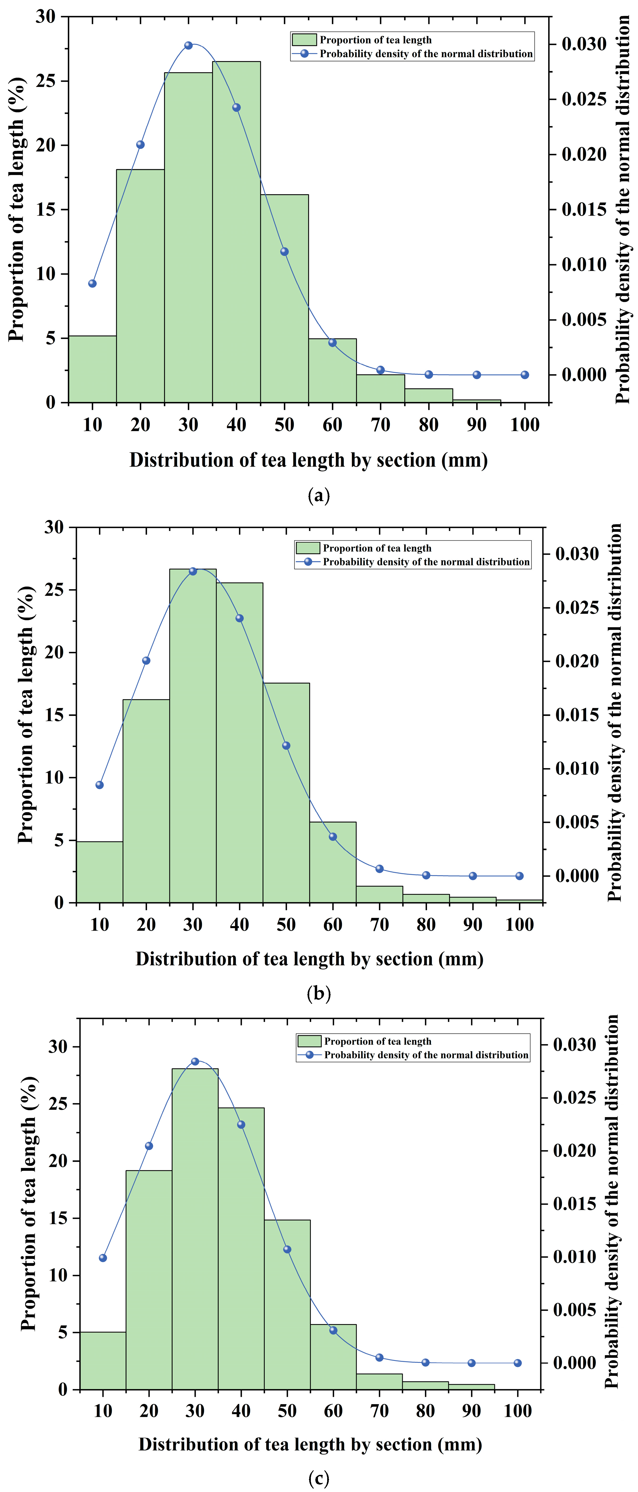
3.3. Evaluation of Harvesting Quality

Table 6 illustrates the statistical outcomes regarding the integrity and missed harvesting rate of tea in diverse sampling segments. For the tea harvested by the experimental prototype, the integrity rates within the three sampling segments stood at 79%, 83%, and 85%, respectively, while the corresponding missed harvesting rates were 0.9%, 1.1%, and 0.8% respectively. The data among each sampling segment exhibited a high degree of consistency. Notably, within the sampling segment where a height difference was present, the tea integrity rate reached 81%, while the missed harvesting rate was recorded at 1.0%. As presented in Table 7, which details the parameters of other types of tea harvesters, an in-depth analysis revealed that, in comparison with the portable tea picker [23], the tea integrity rate of our model was elevated by approximately 13%. Similarly, when contrasted with the ride-on tea picker [20], an approximate 8% enhancement was observed. Moreover, no significant disparity was detected when juxtaposed with the contour-guided tea picker [37,38,39,40], thereby fulfilling the design requisites. The missed harvesting rate of the experimental prototype remained essentially stable at 1%. The missed harvesting rate of the experimental prototype basically stabilized at 1%. The reason for this result was that the harvesting heads of this type of machine all adopted reciprocating harvesters.
As depicted in Figure 14, the distribution of the harvesting length in each sampling segment evidently exhibited a normal distribution tendency. Specifically, the length distributions of tea harvested by the experimental prototype in each sampling segment were highly consistent. The mode of each segment’s height was concentrated around 30 mm, aligning with the set value, and the harvested lengths demonstrated a high concentration near the target setting. Overall, no significant differences were observed in the harvested data across sampling segments, indicating stable harvesting quality of the system. Real tea images during the harvesting trial are presented in Figure 15. Figure 15a displays all the collected tea samples. (note that autumn tea is larger in size due to seasonal growth characteristics); Figure 15b shows the intact tea after screening; and Figure 15c illustrates the statistics of the harvesting lengths of the tea samples.

4. Conclusions

(1)
In this study, a self-adaptive following cutting control system for the tea canopy layer based on a gantry-type vehicle body was designed. It integrates the functions of height following and roll angle correction and is suitable for tea plantations with a slope less than 15° and a ridge height of 40 to 120 cm. It has the advantages of a simple structure, high operation efficiency, and high harvesting quality.
(2)
A dynamic following algorithm for the height of the tea canopy layer was proposed. Through the optimization of data from ultrasonic sensors and the control of speed matching, a height tracking accuracy within ±5 mm (with a correlation coefficient > 0.99) was achieved. By combining with the incremental PID algorithm, the roll angle of the harvester was corrected in real time. The maximum roll angle did not exceed 3.6°, and the leveling time was stabilized within 2.2 s, significantly improving the adaptability to the terrain.
(3)
A prototype was developed, and field tests were carried out. The results showed that when the vehicle speed of the system was 0.4 m/s, the integrity rate of tea reached over 79%, and the missed harvesting rate was lower than 1.1%. The efficiency increased by more than 13% compared with that of traditional handheld or passenger-type tea harvesters, verifying its stability and reliability. It provides a quantifiable and verifiable technical solution for the efficient and low loss harvesting of bulk tea.
This research achieved remarkable results in the height tracking of the tea canopy layer and roll angle correction. However, there is still room for optimization in subsequent studies. Firstly, we should develop a harvester adjustment system capable of adapting to vehicle speed. Secondly, a profiling cutting device for the tea surface is required. Finally, it is essential to develop a small and lightweight vehicle body designed for hilly and mountainous terrains.

Author Contributions

Conceptualization, L.C. and Q.F.; methodology, R.Z., L.Z. and D.Z.; software, T.Y. and D.Z.; validation, T.Y. and D.Z.; formal analysis, R.Z. and D.Z.; investigation, D.Z. and L.Z.; resources, R.Z. and D.Z.; data curation, T.Y. and D.Z.; writing—original draft preparation, D.Z.; writing—review and editing, R.Z.; visualization, D.Z.; supervision, L.C.; project administration, R.Z.; funding acquisition, R.Z. and L.Z. All authors have read and agreed to the published version of the manuscript.

Funding

This research was funded by National Natural Science Foundation of China, grant number U23A20175-2.

Institutional Review Board Statement

Not applicable.

Data Availability Statement

The data presented in this study are available upon request from the corresponding author or first author.

Acknowledgments

We thank the anonymous reviewers for providing comments and suggestions that improved the manuscript.

Conflicts of Interest

The authors declare no conflicts of interest.

References

  1. National Bureau of Statistics. EB/OL. National Data. Available online: https://data.stats.gov.cn/easyquery.htm?cn=C01&zb=A0D0W&sj=2023 (accessed on 5 December 2023).
  2. Chen, T.; Li, H.; Chen, J.; Zeng, Z.; Han, C.; Wu, W. Detection network for multi-size and multi-target tea bud leaves in the field of view via improved YOLOv7. Comput. Electron. Agric. 2024, 218, 108700. [Google Scholar] [CrossRef]
  3. Zhang, W.; Zhao, M.; Chen, Y.; Xu, Y.; Ma, Y.; Fan, S. Low-Carbon Ecological Tea: The Key to Transforming the Tea Industry towards Sustainability. Agriculture 2024, 14, 722. [Google Scholar] [CrossRef]
  4. Zheng, H.; Fu, T.; Xue, X.; Ye, Y.; Yu, G. Research status and prospect of tea mechanized picking technology. J. Chin. Agric. Mech. 2023, 44, 28–35. [Google Scholar]
  5. Li, H.; Chen, T.; Chen, Y.; Han, C.; Lv, J.; Zhou, Z.; Wu, W. Instance Segmentation and 3D Pose Estimation of Tea Bud Leaves for Autonomous Harvesting Robots. Agriculture 2025, 15, 198. [Google Scholar] [CrossRef]
  6. Wang, X.; Tang, D. Research Progress on Mechanical Tea Plucking. Acta Tea Sin. 2022, 56, 275–282. [Google Scholar]
  7. Wang, W.; Song, Z.; Zhao, Y.; Xia, X.; Zhan, C. Research status and development analysis of cultivation management machinery for tea garden. J. Chin. Agric. Mech. 2021, 42, 52–58+218. [Google Scholar]
  8. Wang, M.; Xu, Y.; Zhang, Z.; Zhu, L.; Lin, G. Research progress of intelligent mechanized tea picking technology and equipment. J. Chin. Agric. Mech. 2024, 45, 305–310. [Google Scholar]
  9. Du, Z.; Hu, Y.; Wang, S. Simulation and Experiment of Reciprocating Cutter Kinematic of Portable Tea Picking Machine. Trans. Chin. Soc. Agric. Mach. 2018, 49, 221–226. [Google Scholar]
  10. Jia, J.; Ye, Y.; Cheng, P.; Zhu, Y.; Fu, X.; Chen, J. Design and Experimental Optimization of Hand-held Manipulator for Picking Famous Tea Shoot. Trans. Chin. Soc. Agric. Mach. 2022, 53, 86–92. [Google Scholar]
  11. Wang, S. Research Design and Experimental Study on Portable Electric Tea Plucking Machine. Master’s Thesis, Jiangsu University, Zhenjiang, China, 2018. [Google Scholar]
  12. Liu, H.; He, F.; Li, R.; He, H.; Wang, Y. Design and Test of Portable Vacuum Absorption Tea Collector. J. Agric. Mech. Res. 2021, 43, 110–114. [Google Scholar]
  13. Wu, X.; Li, B.; Wang, X.; Li, S.; Zeng, C. Design and Analysis of Single Knapsack Tea Plucking Machine. J. Agric. Mech. Res. 2017, 39, 92–96+101. [Google Scholar]
  14. Han, Y.; Song, Z.; Chen, Q.; Mei, S.; Yang, G. Optimization and experiment of arc type reciprocating double-acting tea picking cutter. Trans. Chin. Soc. Agric. Eng. 2022, 38, 35–43. [Google Scholar]
  15. Song, Y.; Li, W.; Li, B.; Zhang, Z. Design and Test of Crawler Type Intelligent Tea Picker. J. Agric. Mech. Res. 2020, 42, 123–127. [Google Scholar]
  16. Han, Y.; Xiao, H.R.; Song, Z.Y.; Chen, Q.M.; Ding, W.Q.; Mei, S. Design and experiments of 4CJ-1200 self-propelled tea plucking machine. Int. J. Agric. Biol. Eng. 2021, 14, 75–84. [Google Scholar] [CrossRef]
  17. Wu, Z.; Chen, L.; Wang, Y.; Luo, K.; Lai, Y.; Zhang, X.; Cao, C. Design and Experiment on Traversibility of Traveling Chassis of Crawler Self-propelled Tea Picker. Trans. Chin. Soc. Agric. Mach. 2025, 56, 474–483. [Google Scholar]
  18. Wang, P.; Yi, W.; Xiong, C.; Cheng, F.; Deng, J.; Zhou, Y.; Geng, Y.; Wu, J. Design and Test of 4CJZ-1000 Self-propelled Tea Picker. J. Southwest Univ. (Nat. Sci. Ed.) 2022, 44, 228–233. [Google Scholar]
  19. Tang, Y.; Han, W.; Hu, A.; Wang, W. Design and Experiment of Intelligentized Tea-plucking Machine for Human Riding Based on Machine Vision. Trans. Chin. Soc. Agric. Mach. 2016, 47, 15–20. [Google Scholar]
  20. Yan, J. Optimization Research on the Optimal Design of the Profiling Tea Picking Machine and Its Coordination with Tea Garden Management. Master’s Thesis, Anhui Agricultural University, Hefei, China, 2019. [Google Scholar]
  21. Huan, X.; Wu, M.; Bian, X.; Jia, J.; Kang, C.; Wu, C.; Zhao, R.; Chen, J. Design and Experiment of Ordinary Tea Profiling Harvesting Device Based on Light Detection and Ranging Perception. Agriculture 2024, 14, 1147. [Google Scholar] [CrossRef]
  22. Zhao, R.; Bian, X.; Chen, J.; Dong, C.; Wu, C.; Jian, J.; Mao, M.; Xiong, Y. Development and Test for Distributed Control Prototype of the Riding Profiling Tea Harvester. J. Tea Sci. 2022, 42, 263–276. [Google Scholar]
  23. Bian, X. Design and Experiment on the Height Perception Method of Ordinary Tea Canopy and the Profiling Harvesting Device of the Riding Tea Picker. Master’s Thesis, Zhejiang Sci-Tech University, Hangzhou, China, 2023. [Google Scholar]
  24. Wu, M.; Huan, X.; Chen, J.; Dong, C.; Shao, B.; Bian, X.; Fan, G. Research and Experiment on Profiling Method of Tea Picker Based on Fusion of 2D-LiDAR and Attitude and Heading Reference System. J. Tea Sci. 2023, 43, 135–145. [Google Scholar]
  25. Yu, S.; Liu, Y.; Chen, W.; Ren, J.; Zheng, S. Design and analysis of tea-plucking device with adaptive adjustment of cutter. J. Chin. Agric. Mech. 2024, 45, 36–41+167. [Google Scholar] [CrossRef]
  26. Zhang, S.; Yang, H.; Yang, C.; Yuan, W.; Li, X.; Wang, X.; Zhang, Y.; Cai, X.; Sheng, Y.; Deng, X.; et al. Edge Device Detection of Tea Leaves with One Bud and Two Leaves Based on ShuffleNetv2-YOLOv5-Lite-E. Agronomy 2023, 13, 577. [Google Scholar] [CrossRef]
  27. Yu, R.; Xie, Y.; Li, Q.; Guo, Z.; Dai, Y.; Fang, Z.; Li, J. Development and Experiment of Adaptive Oolong Tea Harvesting Robot Based on Visual Localization. Agriculture 2024, 14, 2213. [Google Scholar] [CrossRef]
  28. Weng, X.; Tan, D.; Wang, G.; Chen, C.; Zheng, L.; Yuan, M.; Li, D.; Chen, B.; Jiang, L.; Hu, X. CFD Simulation and Optimization of the Leaf Collecting Mechanism for the Riding-Type Tea Plucking Machine. Agriculture 2023, 13, 946. [Google Scholar] [CrossRef]
  29. Li, Y.; Wu, S.; He, L.; Tong, J.; Zhao, R.; Jia, J.; Chen, J.; Wu, C. Development and field evaluation of a robotic harvesting system for plucking high-quality tea. Comput. Electron. Agric. 2023, 206, 107659. [Google Scholar] [CrossRef]
  30. Fu, T. Design and Test of Tea Self-Adaptive Profiling Picking Device. Master’s Thesis, Zhejiang University of Science and Technology, Hangzhou, China, 2024. [Google Scholar]
  31. Shen, H.; Ji, E.; Ding, W.; Deng, J.; Hua, Y.; Li, T. Mechanism Design and Dynamic Balance Analysis of a 6-DOF Hybrid Robot for Tea-picking. Trans. Chin. Soc. Agric. Mach. 2023, 54, 416–426. [Google Scholar]
  32. Li, Y.; He, L.; Jia, J.; Lv, J.; Chen, J.; Qiao, X.; Wu, C. In-field tea shoot detection and 3D localization using an RGB-D camera. Comput. Electron. Agric. 2021, 185, 106149. [Google Scholar] [CrossRef]
  33. Zhu, Y.; Wu, C.; Tong, J.; Chen, J.; He, L.; Wang, R.; Jia, J. Deviation Tolerance Performance Evaluation and Experiment of Picking End Effector for Famous Tea. Agriculture 2021, 11, 128. [Google Scholar] [CrossRef]
  34. Wei, Y.; Wen, Y.; Huang, X.; Ma, P.; Wang, L.; Pan, Y.; Lv, Y.; Wang, H.; Zhang, L.; Wang, K.; et al. The dawn of intelligent technologies in tea industry. Trends Food Sci. Technol. 2024, 144, 104337. [Google Scholar] [CrossRef]
  35. Sun, Z.; Xia, C.; Jiang, Y.; Guo, Y.; Wang, R. Omnidirectional Leveling Control of Crawler Machine Based on QBP-PID. Trans. Chin. Soc. Agric. Mach 2023, 54, 397–406. [Google Scholar]
  36. NY/T 2614-2014; Operating Quality for Tea Picking Machines. Ministry of Agriculture of the People’s Republic of China: Beijing, China, 2014. Available online: https://hbba.sacinfo.org.cn/attachment/onlineRead/14a3d271fdc0dc963b32f4430d316222e978c034ef2a04d584b52fb56589da44 (accessed on 10 June 2023).
  37. Yu, S. Optimization Design and Experimental Study of Tea-Plucking Machine with Adaptive Adjustment of Cutter. Master’s Thesis, Fujian Agriculture and Forestry University, Fuzhou, China, 2024. [Google Scholar]
  38. Wang, Q. Design and Experimental Study of a Tea Picker with Adaptive Adjustment of Cutter Height. Master’s Thesis, Fujian Agriculture and Forestry University, Fuzhou, China, 2018. [Google Scholar]
  39. Han, Y.; Song, Z.; Chen, Q. Design and experiment of 4CJ-1200F intelligent tea plucking machine. J. Intell. Agric. Mech. (Chin. Engl.) 2022, 3, 1–6. [Google Scholar]
  40. Zhe, D. Research on Biomimetic Design of Cutting Blade for Tea Stem and Its Cutting Performance. Ph.D. Thesis, Jiangsu University, Zhenjiang, China, 2020. [Google Scholar]
Figure 1. Cutting control system. Fixed height adjustment mechanism (FHAM), guide rod (GR), installation rack (IR), and angle limit rod (ALR).
Agriculture 15 00557 g001
Figure 2. Working principle diagram of the whole machine.
Agriculture 15 00557 g002
Figure 3. Operational principle of the control system. In the figure, the black dashed line indicates the ground, the yellow dashed line indicates the target cutting trajectory. (a) front view; (b) right view.
Agriculture 15 00557 g003
Figure 4. Tea canopy height detection error.
Agriculture 15 00557 g004
Figure 5. Cutting height tracking schematic. In the figure, the blue dashed line indicates the tea canopy height, and the yellow dashed line indicates the target cutting trajectory.
Agriculture 15 00557 g005
Figure 6. The initial angle of the cutter surface in the horizontal state. In the figure, the thick red solid arrow represents T0. The thick black solid arrow represents G.
Agriculture 15 00557 g006
Figure 7. Schematic diagram of harvester roll angle PID control.
Agriculture 15 00557 g007
Figure 8. Field calibration of ultrasonic sensor errors.
Agriculture 15 00557 g008
Figure 9. Schematic diagram of the stability test for the roll angle correction of the harvester. (a) represents that the left side of the vehicle body is higher; (b) represents that the vehicle body is horizontal, and (c) represents that the right side of the vehicle body is higher.
Agriculture 15 00557 g009
Figure 10. The tea picker harvesting tea in the tea plantation. (a) Scenario with uniform height of paths between tea ridges; (b) Scenario with height differences in paths between tea ridges.
Agriculture 15 00557 g010
Figure 11. Cutting trajectory diagrams for different harvesting lengths.
Agriculture 15 00557 g011
Figure 12. A comparison of the target and actual values of the cutting height. (a) shows the tracking trend of harvesting length 20 mm experiment; (b) shows the tracking trend of harvesting length 30 mm experiment, and (c) shows the tracking trend of harvesting length 40 mm experiment.
Agriculture 15 00557 g012
Figure 13. The distribution of the harvester roll angle (HRA) and vehicle roll angle (VRA) when the vehicle body tilts left and right under different height differences of ridged fields. In the figure, the annotations a, b, c, d, and e correspond to the quintessential phases of the vehicle’s traversal: the before going uphill (a), going uphill (b), at the top of the hill (c), going downhill (d), and after going downhill (e), respectively. The widths of the black dashed lines on both sides of b and d represent the time required for the harvester angle correction during uphill and downhill, respectively. (a) H = 10 cm (Left side high); (b) H = 10 cm (Right side high); (c) H = 15 cm (Left side high); (d) H = 15 cm (Right side high); (e) H = 20 cm (Left side high); (f) H = 20 cm (Right side high).
Agriculture 15 00557 g013aAgriculture 15 00557 g013b
Figure 14. The length distribution of harvested tea. (ac) are under the condition of uniform height of paths between tea ridges, and (d) is under the condition of height differences in paths between tea ridges.
Agriculture 15 00557 g014aAgriculture 15 00557 g014b
Figure 15. Field image of tea collected during the experiment. (a) All tea in the collection bag; (b) Screened intact tea; (c) Length statistics of tea.
Agriculture 15 00557 g015
Table 1. Key parameters of vehicle.
External
Dimensions
/mm
Max Speed/
m/s
Max Roll
Angle/°
Drive ModeTrack Width
/mm
Track Grounding Length
/mm
Motor Power
/W
2150 × 1950 × 22501.520Crawler-type135011002 × 850
Table 2. Key parameters of harvester.
External Dimensions
/mm
Cutting Width
/mm
Cutting Blade ShapeDrive ModeMax Power
/W
Fan Speed
/r/min
Frequency
/Hz
1470 × 580 × 4601200Flat typeTwo-stroke gasoline engine22003602.78
Table 3. Measurement error of ultrasonic sensor at different distances.
Distance200 mm300 mm400 mm500 mm600 mm
Maximum error/mm2−2−323
Table 4. RMSE, PCC, and MAE values for three cutting heights.
Cutting Height/mmRMSE/mmPCCMAE/mm
203.450.99142.98
303.590.99582.93
403.620.99592.95
Table 5. The values of ADA and ART are at three different slopes.
Base Height/cmAverage Maximum Deflection Angle/°Average Recovery Level Time/s
LeftRightLeftRight
10Uphill1.71.62.81.7
Downhill1.31.42.12.0
15Uphill2.62.51.71.8
Downhill2.01.92.12.2
20Uphill3.63.51.81.6
Downhill2.52.62.22.1
Table 6. Harvesting quality of three samples.
Sampling SegmentTea Integrity Rate/%Tea Missed Harvesting Rate/%
I790.9
II831.1
III850.8
Height difference811.0
Table 7. Comparison of operation quality parameters across different machine models.
Machine ModelsTea Integrity Rate/%Tea Missed Harvesting Rate/%
Convenient machine≈70≈1
Passenger vehicle≈80≈1
Other copying machines≈80≈0.9
Disclaimer/Publisher’s Note: The statements, opinions and data contained in all publications are solely those of the individual author(s) and contributor(s) and not of MDPI and/or the editor(s). MDPI and/or the editor(s) disclaim responsibility for any injury to people or property resulting from any ideas, methods, instructions or products referred to in the content.

