1. Introduction
Unmanned agricultural machinery driving constitutes the core of intelligent agricultural development, effectively reducing labor requirements and enhancing agricultural productivity [
1,
2,
3]. Currently, unmanned autonomous navigation primarily involves constructing a scene map, acquiring the vehicle’s pose via GNSS positioning technology, planning operational paths, and enabling the machinery to follow these paths through path-tracking algorithms to accomplish unmanned field operations [
4,
5]. Autonomous operations in exiting/entering machinery sheds and traveling on farm access roads are essential components of fully unmanned agricultural production. However, agricultural machinery sheds are often enclosed or semi-enclosed environments where GNSS signals are obstructed, while on farm access roads, trees on both sides can cause GNSS signal drift. As a result, existing GNSS-based automatic navigation systems cannot operate in these environments, leaving no alternative to manual driving. Therefore, it is particularly imperative to develop an autonomous navigation system suitable for machinery sheds and farm access road environments.
At present, automatic navigation systems for agricultural machinery primarily adopt two technical approaches: GNSS-based positioning and vision-based perception [
6,
7]. Ryosuke Takai et al. [
8] proposed a navigation system integrating RTK-GPS and IMU. Through tractor navigation experiments, the lateral error in straight-line segments was less than 0.05 m. Kubota’s unmanned harvester utilizes RTK-GPS and IMU fusion positioning technology. By incorporating tilt compensation for acceleration and angular velocity on uneven fields, it corrected tilt errors and achieved high-precision navigation and positioning. Hu Ziqian [
9] employed Beidou RTK dual antennas (China) and an angle sensor to acquire steering angle and position information, verifying the reliability of the harvester’s navigation system. The aforementioned studies are all based on GNSS navigation, mostly using sensor fusion with IMU, etc., to enhance vehicle positioning accuracy. However, in environments with no or weak GNSS signals, obtaining the vehicle’s pose in real time is challenging, making autonomous navigation unfeasible. For vision-based navigation methods, navigation is primarily achieved through image processing operations to fit and track vehicle navigation lines. Sristi Saha et al. [
10] proposed a vision-based automatic navigation system for tractors, which distinguishes between traversable and non-traversable areas via images. Meng Qingkuan et al. [
11] introduced a method for operation recognition and navigation line extraction based on machine vision, enabling rapid detection of navigation lines. Zhai Zhiqiang et al. [
12] presented a crop row recognition method based on the Census transform from binocular vision; the identified navigation lines can meet the accuracy and real-time requirements for field navigation. Since visual navigation is highly sensitive to variations in lighting, it fails to obtain effective information under intense or low light conditions. Moreover, agricultural machinery sheds are mostly enclosed or semi-enclosed environments with dim internal light, where visual navigation also struggles to function effectively. Even on farm access roads, visual navigation is susceptible to strong light, leading to unstable detection performance. In summary, existing navigation research is not suitable for machinery sheds and farm access road environments.
Simultaneous Localization and Mapping (SLAM) [
13] utilizes sensor-scanned data to achieve self-localization and map construction in unknown environments, thereby addressing issues such as GNSS signal loss and significant visual perception errors in complex unfamiliar settings. Laser SLAM [
14,
15] employs LiDAR point cloud data as input to build navigation maps, while visual SLAM [
16,
17,
18] relies on image feature points for map construction. Zubaidah et al. [
19] used the Gmapping algorithm to generate an environmental map and planned global and local paths for an agricultural robot. Sayed et al. [
20] adopted a 2D laser SLAM method to accomplish navigation tasks for disinfection robots across various terrains. Abdelaziz et al. [
21] proposed a navigation system that integrates INS, LiDAR, and stereo visual SLAM using an Extended Kalman Filter, improving the positioning accuracy of the system. Li Chenyang et al. [
22] developed a localization and mapping method for agricultural robots that incorporates odometry information. By integrating odometry data into the Gmapping algorithm, they reduced the impact of LiDAR motion distortion on mapping. Song Huaibo et al. [
23] utilized LiDAR combined with the Cartographer algorithm (which incorporates odometry) for position determination, enabling autonomous hay rolling operations. Hu Lian et al. [
24] achieved robot pose estimation by analyzing LiDAR time differences and point cloud features. Most of the aforementioned studies focus on relatively simple indoor environments. However, in agricultural machinery sheds characterized by dim lighting, compact space, and numerous scattered obstacles—both 2D laser SLAM and visual SLAM struggle to accurately represent the environmental features. In farm access road environments, where non-navigable areas such as trees and ditches exist on both sides of the path, 2D laser SLAM cannot adequately characterize these features, while visual SLAM remains susceptible to variations in natural lighting conditions.
In the field of 3D mapping, LeGO-LOAM, LIO-SAM, FAST-LIO2, and Cartographer represent mainstream LiDAR SLAM algorithms, each with distinct strengths in different application scenarios. Agricultural machinery sheds and farm access roads typically feature well-defined ground planes and abundant structural elements (such as ridges and ditches), making them particularly suitable for LeGO-LOAM. This algorithm leverages lightweight design and specialized optimization for ground features, employing point cloud segmentation to extract ground planes and perform efficient feature matching, thereby demonstrating unique applicability in such environments. Moreover, its low computational complexity makes it highly suitable for embedded platforms with limited resources, such as those used in agricultural machinery. In contrast, while LIO-SAM and FAST-LIO2 achieve higher precision, they strongly rely on high-quality IMUs, which is problematic given the substantial vibration and cost sensitivity of agricultural equipment. Similarly, Cartographer’s loop closure detection offers limited benefits in feature-sparse agricultural settings. Therefore, while meeting essential navigation accuracy requirements, LeGO-LOAM provides a practical solution that strikes an optimal balance between cost, computational demand, and performance for field automation.
Therefore, targeting the complex operational scenarios involving agricultural machinery sheds and farm access roads, this study develops an autonomous navigation system for tracked grain transport vehicles, integrating LiDAR, GNSS, and IMU sensors. By employing SLAM technology for environmental mapping, we introduce an enhanced LeGO-LOAM algorithm that improves point cloud mapping accuracy and mitigates issues associated with vision-based perception—such as sensitivity to lighting variations and environmental interference. Furthermore, an UKF is implemented to fuse positioning estimates from the NDT algorithm with IMU measurements, thereby enhancing localization precision. This integrated approach enables unmanned operation of tracked grain vehicles during shed entry/exit and travel along farm access roads, ultimately improving the efficiency of field-based grain logistics.
2. Material and Methods
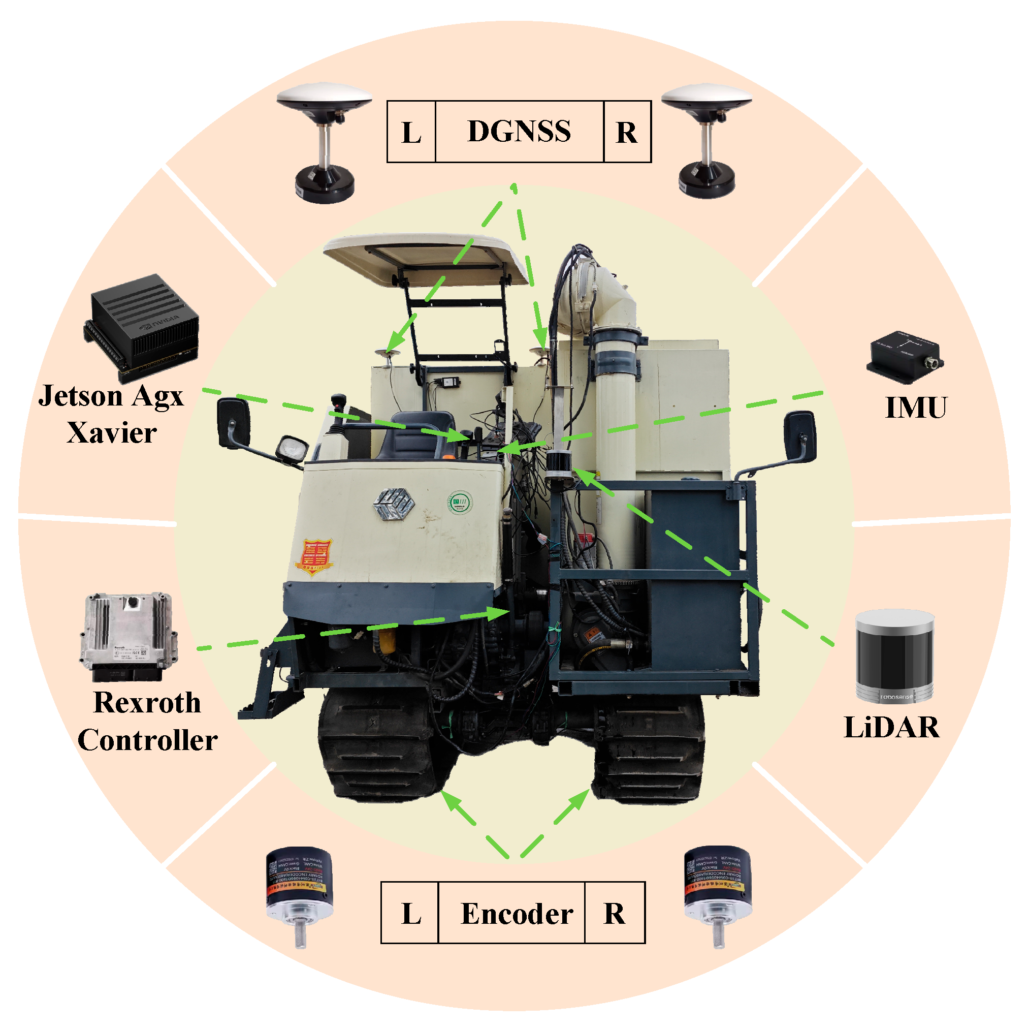
The hardware of the autonomous navigation system for the tracked grain transport vehicle consisted primarily of a perception module, a control module, and an execution module, as shown in
Figure 1. The perception module was mainly composed of sensors, including a Helios-16 LiDAR (RoboSense Technology Co., Ltd., Shenzhen, China), a NC502-D GNSS receiver (BDStar Navigation Co., Ltd., Beijing, China), and a N200WP IMU (Wheel-tec Co., Ltd., Dongguan, China). It was used to construct a map of the machinery sheds and farm access roads environments and acquire real-time localization of the vehicle. The control module primarily referred to the edge computing platform (Jetson AGX Xavier, Nvidia, Santa Clara, CA, USA) acting as the upper computer, which was used to deploy executable files of the navigation system. The execution module mainly consisted of the hydraulic controller (Rexroth, Lohr am Main, Germany) and the chassis hydraulic regulation module. The lower computer receives decision commands from the upper computer, sends current values to the hydraulic solenoid valves, and controls the chassis hydraulic module to realize traveling and steering functions of the tracked chassis.
2.1. Software Architecture
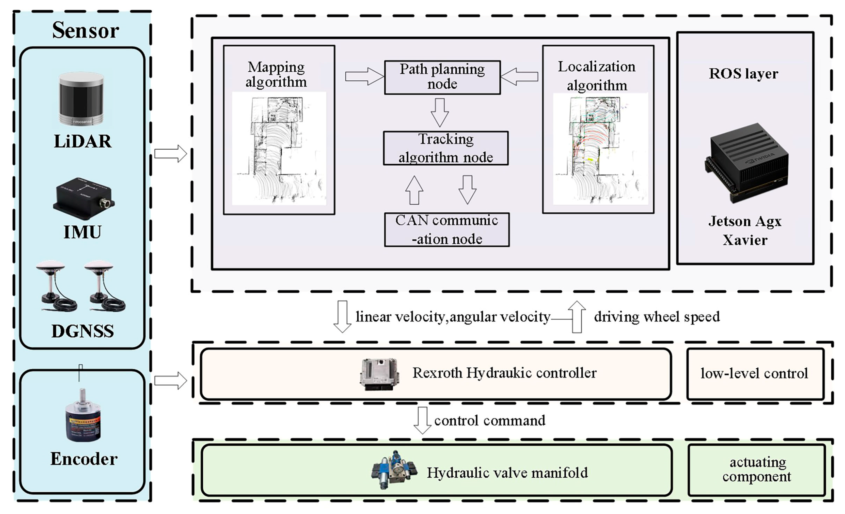
The software architecture of the autonomous navigation system for the tracked grain transport vehicle was divided into functional modules, including high-precision mapping, real-time localization, path planning, and tracking control. The overall software architecture is shown in
Figure 2.
Mapping Module: It was primarily responsible for processing the point cloud data transmitted by the LiDAR and employed mapping algorithms to construct a point cloud map of complex environments. Real-Time Localization Module: This module utilized localization algorithms integrated with real-time sensor data to estimate the vehicle’s real-time localization within the map. Path Planning Module: Based on the constructed point cloud map, a path planning algorithm generated an optimal trajectory that avoids static obstacles in the environment. Tracking Control Module: According to the planned optimal path, a path tracking algorithm computed the desired linear and angular velocity commands, which were sent to the lower computer hydraulic controller to drive the tracked chassis for straight-line motion or steering, thereby accomplishing autonomous navigation tasks. The communication architecture of the software system in this study was implemented based on the ROS (Robot Operating System, Open Robotics, USA) framework, where the four functional modules interact through topics, services, and the parameter server to achieve inter-module communication.
2.2. High-Precision Mapping System
Unstructured agricultural environments such as machinery sheds and farm access roads are highly complex. Machinery sheds often feature uneven floors, hanging obstacles on walls, and scattered grain piles, while farm access roads exhibit irregular terrain and disorderly grown trees along the sides, posing significant challenges for mapping. The LeGO-LOAM algorithm [
25], based on a 3D laser SLAM framework, incorporates point cloud segmentation and loop closure detection, which effectively separates ground and non-ground points, improves the accuracy of feature extraction and matching, and reduces cumulative mapping errors. However, due to the specific complexities of agricultural sheds and farm access road environments, directly applying the LeGO-LOAM algorithm may lead to the following issues: (1) The intricate environments may capture invalid point cloud data with weak reflectivity, which impairs point cloud processing efficiency; (2) Uneven terrain induces LiDAR scanning errors, and prolonged operation accumulates drift that severely affects final mapping accuracy. Therefore, this paper improves the LeGO-LOAM algorithm to construct high-precision 3D maps in such challenging shed and field access road environments.
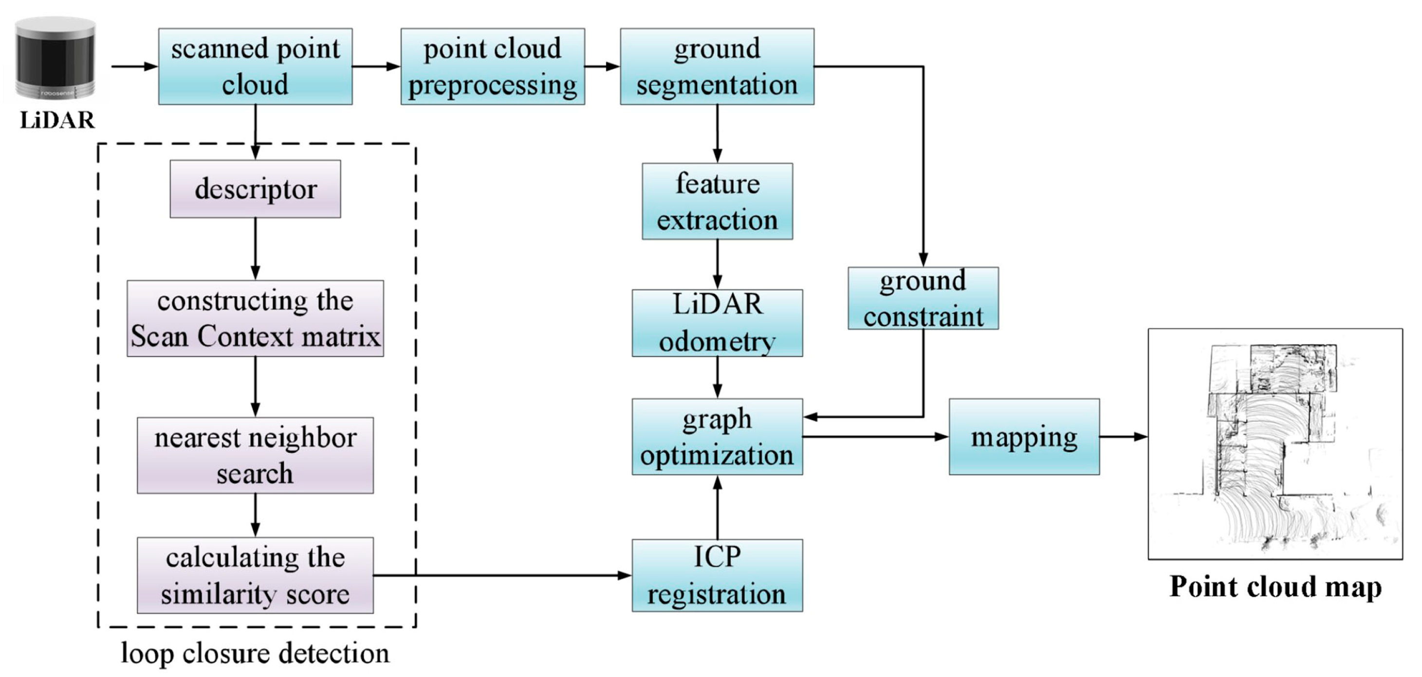
As shown in
Figure 3, this study introduces several key improvements to the LeGO-LOAM algorithm: (1) intensity-based filtering of feature point clouds is implemented to exclude invalid points with excessively low or high reflectance values, thereby reducing mapping interference and improving computational efficiency; (2) the original ground segmentation method has been enhanced by incorporating ground constraints as additional factors in the graph optimization process, which mitigates vertical drift and improves pose estimation accuracy; (3) the conventional Euclidean distance-based loop closure detection in LeGO-LOAM has been replaced with the Scan Context method, addressing the limitations of ICP registration and significantly enhancing loop detection reliability for globally consistent point cloud mapping. The improved LeGO-LOAM algorithm can be divided into five main steps.
Voxel grid filtering and intensity threshold filtering are applied to the raw point cloud to quickly remove noise and invalid points;
Height thresholding, normal vector filtering, and RANSAC fitting are used to simultaneously extract the ground point cloud and ground plane parameters, with the latter serving as constraints for graph optimization;
Edge and planar features are extracted from the non-ground point cloud, and the relative pose is estimated through inter-frame feature matching;
ScanContext is employed to convert the 3D point cloud into a 2D image descriptor, enabling highly robust loop closure detection;
Odometry, loop closure, and ground constraints are integrated into a factor graph optimization framework to output accurate global poses and the consistent map.
The LiDAR intensity range used in this study is 0–255. Based on preliminary point cloud data collection experiments, the intensity filter thresholds were set to [30, 220]. The lower threshold of 30 filters invalidates weak reflections from dust and shadows, while the upper threshold of 220 filters oversaturates points from metal surfaces or specular reflections in the environment. The ground segmentation parameters were also defined: ground point vertical distance threshold of 0.15 m, minimum number of ground points set to 50, and the maximum angle between the ground normal vector and the vertical direction set to 15°. The resulting ground constraint factors for graph optimization are [0.1, 0.1, 0.01, 0.05, 0.05, 0.5].
2.3. Real-Time Localization System
Based on the pre-built 3D point cloud maps of the machinery sheds and farm access roads environments, the tracked grain transport vehicle must determine its own pose within the map in real time to facilitate subsequent path planning and tracking control. Typically, the NDT algorithm [
26] is employed to register the real-time point cloud frames, acquired by LiDAR scans, with the prior point cloud map, thereby estimating the real-time localization of the vehicle and providing localization information. The NDT algorithm is a registration algorithm based on the standard normal distribution. It divides the target point cloud space into a series of grids and calculates the normal distribution parameters of the point cloud in each grid. Based on these parameters, the probability of each transformation point in the registered point cloud is computed. When the probability reaches its maximum, it indicates that the optimal registration relationship has been found. This algorithm features low computational load and fast registration speed, meeting the real-time requirements for this study.
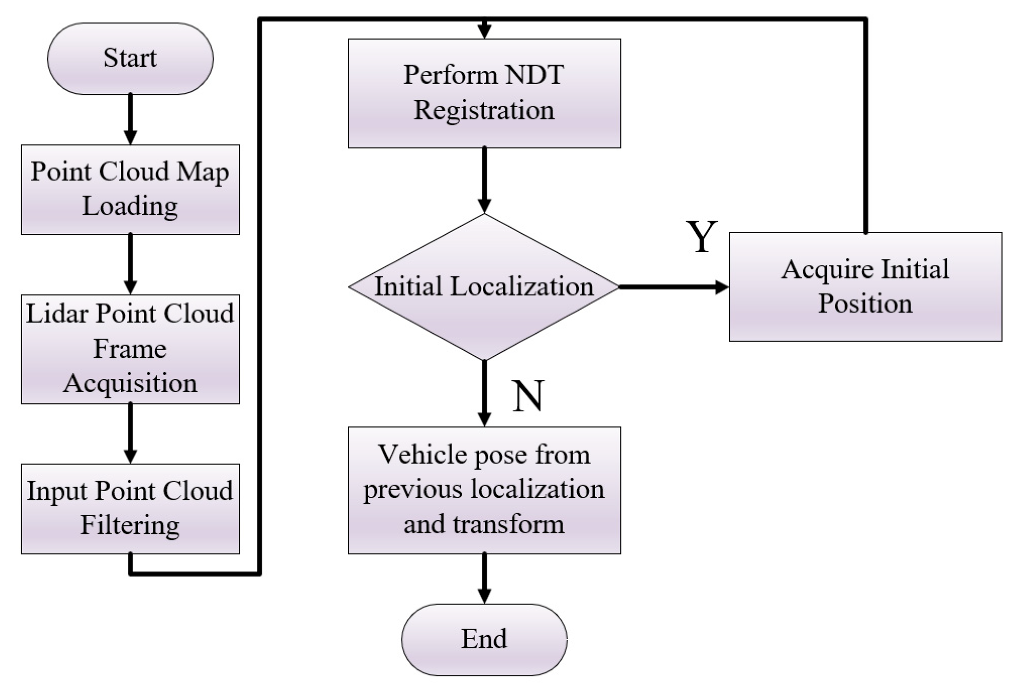
However, the NDT algorithm (as
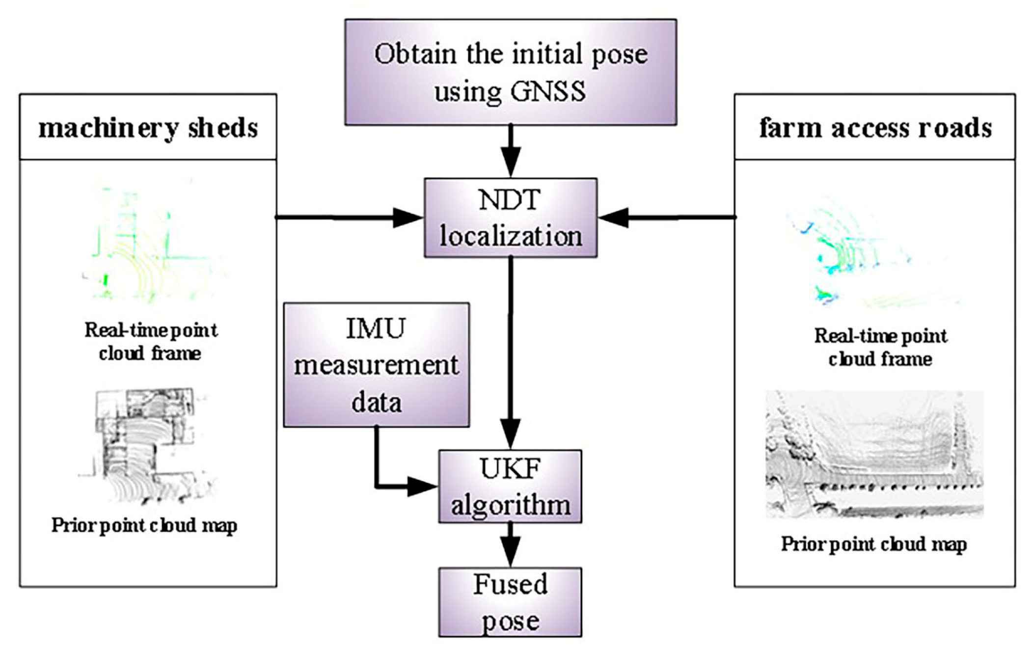
Figure 4) suffers from low registration accuracy, leading to considerable errors in localization estimation. To address this issue, this paper utilizes the UKF to fuse the localization estimated by NDT with IMU data, thereby improving localization accuracy while maintaining computational efficiency.
The procedural flow of the UKF algorithm is as follows:
The Unscented Transform assumes a nonlinear transformation
y =
f(
x), where the state vector is an n-dimensional random variable. Given a mean
μ and a covariance
P, the Unscented Transform generates 2
n + 1 sigma points and their corresponding weights
χ, enabling the computation of the statistics of
y, as specified by Equation (1).
Equation (2) above provides the calculation formula for the mean weights, where . Here, α and k determine the spread of the sigma points around the mean. A smaller value of brings the points closer to the mean of the state.
The state model and observation model of the grain transport vehicle are given by Equation (3) and Equation (4), respectively.
In Equation (3), represents the pose of the grain transport vehicle at time step k + 1, where and denote error terms.
The sigma points are propagated through the state model of the grain transport vehicle to obtain the transformed sigma points
. Then, the mean
and covariance
of the prior state distribution are computed. Simultaneously, by incorporating the sensor noise, the mean
and covariance
of the prior observation distribution are obtained. Subsequently, the cross-correlation between the state vector and the observation vector is calculated using the sigma points, as given in Equation (5).
Finally, the system state is updated following the Kalman filtering procedure, as shown in Equation (6). The Unscented Kalman Filter fuses the results from the prediction and observation equations, iteratively refines the pose, and ultimately outputs the refined sensor pose.
As shown in
Figure 5, the localization scheme for the grain transport vehicle is described as follows: In the machinery shed environment, an initial value was first manually assigned to the Normal Distribution Transform (NDT) algorithm based on the pre-built point cloud map, preventing the registration process from converging to a local optimum and improving the convergence speed of the NDT algorithm. Subsequently, the localization estimated by the NDT algorithm was used as the observation value, while the IMU measurement data served as the state value. The Unscented Kalman Filter (UKF) was then applied to fuse these inputs, yielding an accurate and robust localization estimation of the vehicle. Unlike the machinery shed environment, GNSS signals had been available in the farm access roads environment. Therefore, GNSS positioning data were utilized to provide the initial value for the NDT registration process, eliminating the need for manual initialization. Once the initial position of the vehicle was determined, the UKF was employed to integrate the NDT-derived localization estimates with IMU measurements, thereby achieving reliable localization of the grain transport vehicle.
Through preliminary point cloud map registration experiments, the system state parameters and covariance matrices were initialized. With a system state dimension of 6, the UKF parameters were set as: α = 0.001, β = 2, κ = 0. The process noise covariance matrix Q = [0.1, 0.1, 0.1, 0.1, 0.1, 0.1] and the observation noise covariance matrix R = [0.5, 0.5, 0.05]. The derived system control parameters are as follows: NDT resolution of 0.5 m, UKF update frequency of 10 Hz (IMU: 100 Hz, NDT: 5 Hz), and system convergence thresholds of position error <0.15 m and angle error < 0.05 rad.
3. Experiment and Discussion
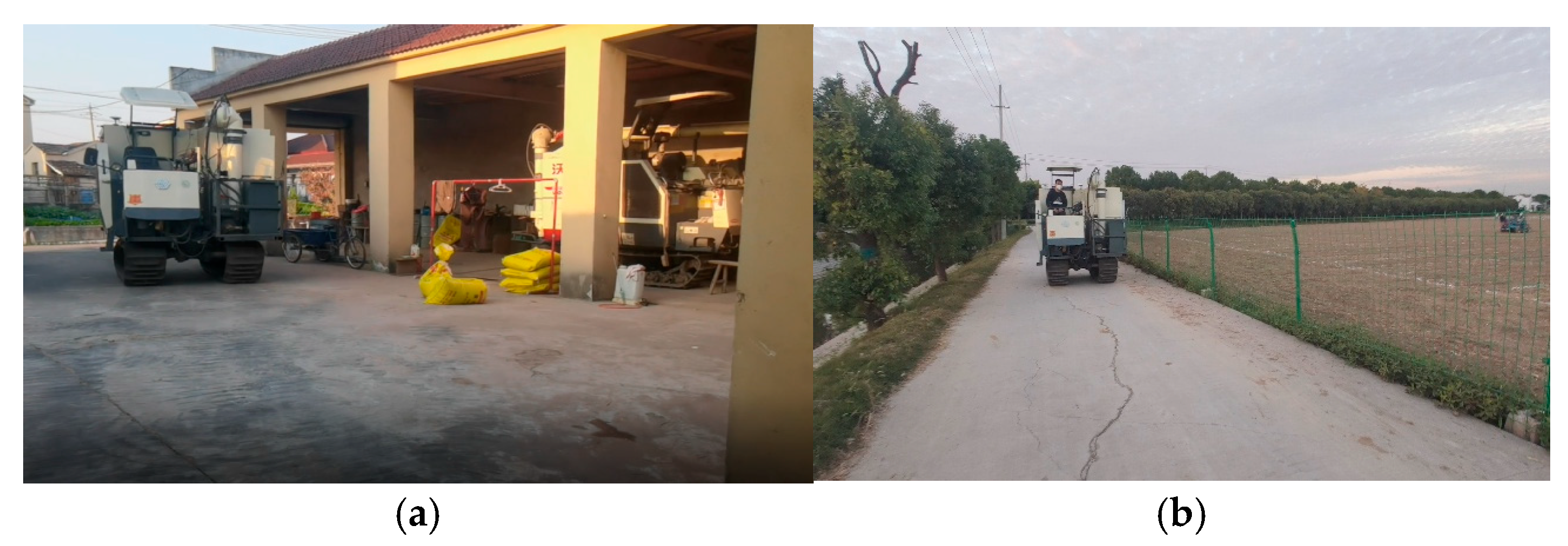
To evaluate the performance of the proposed mapping and real-time localization method, field experiments were conducted from 10 to 15 November 2024, in scenarios involving agricultural machinery sheds and farm access roads. The tests were carried out in Weixing Village, Shiye Town, Zhenjiang City, Jiangsu Province, as illustrated in
Figure 6. The agricultural machinery shed comprises four bays, each measuring approximately 6.2 m in length, 4.1 m in width, and 3.8 m in height, dimensions that accommodate most common types of agricultural machinery. The farm access road features a cement-hardened surface and is flanked by trees, drainage ditches, and farmland. The test route was divided into two segments: straight-path driving and right-angle turning.
3.1. Mapping Experiments
A LiDAR sensor was mounted at the front of the tracked grain transport vehicle, which was then driven through the machinery shed and along the farm access road to collect the required 3D point cloud data.
- (1)
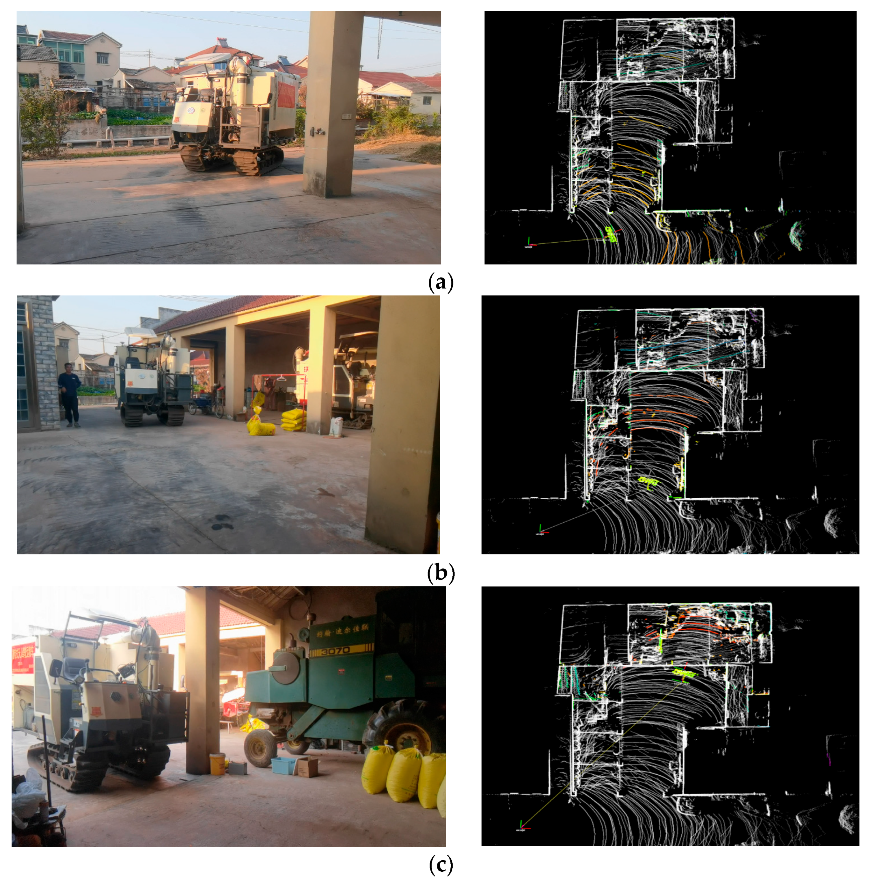
Mapping During Shed Navigation. The vehicle entered the shed from the access road via a turning maneuver, and then proceeded to a parking bay through consecutive directional changes.
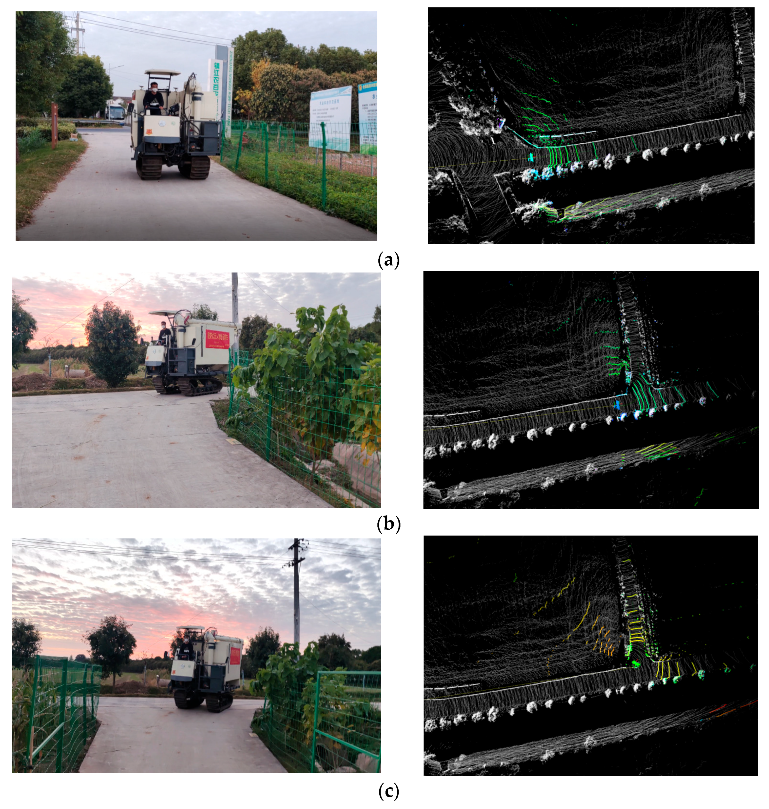
Figure 7 illustrates the autonomous entry process of the tracked vehicle into the shed, showing the mapping results at four representative timestamps during the procedure.
- (2)
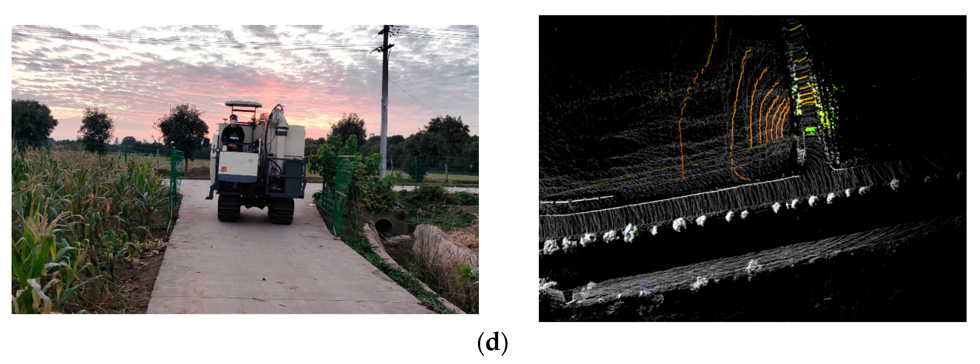
Mapping During Road Navigation. The vehicle started from a designated point on the farm access road and advanced through a combination of straight-line travel and turning maneuvers to reach a target location. As shown in
Figure 8, the autonomous navigation process along the road is depicted at four timestamps, covering both straight-path segments and a right-angle turn.
- (3)
Comparison of mapping results before and after the improvements to the LeGO-LOAM algorithm. This study employed both the original and improved versions of the LeGO-LOAM to conduct mapping in the environments of the machinery sheds and the farm access roads. By acquiring point cloud data from the actual shed and road scenarios, we validated the advancements of the improved algorithm.
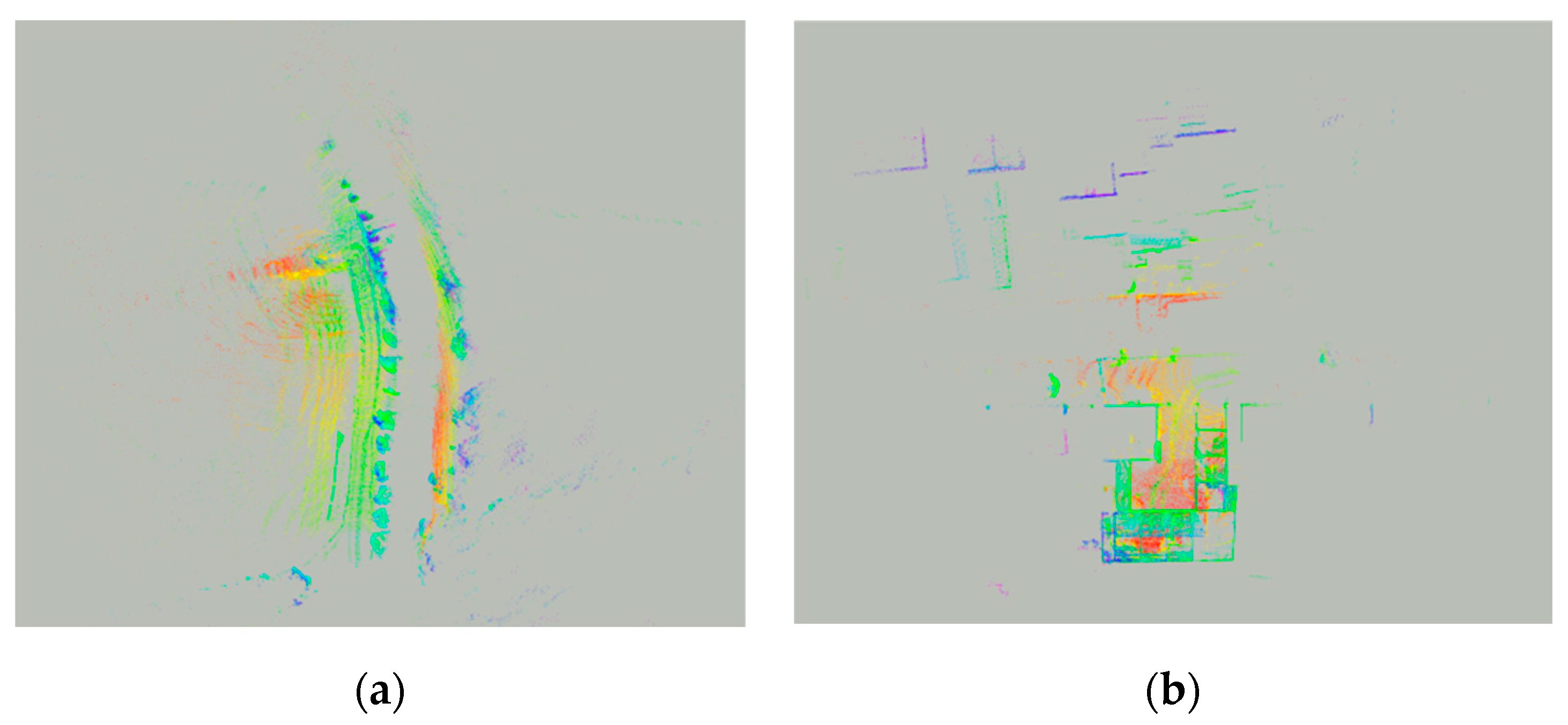
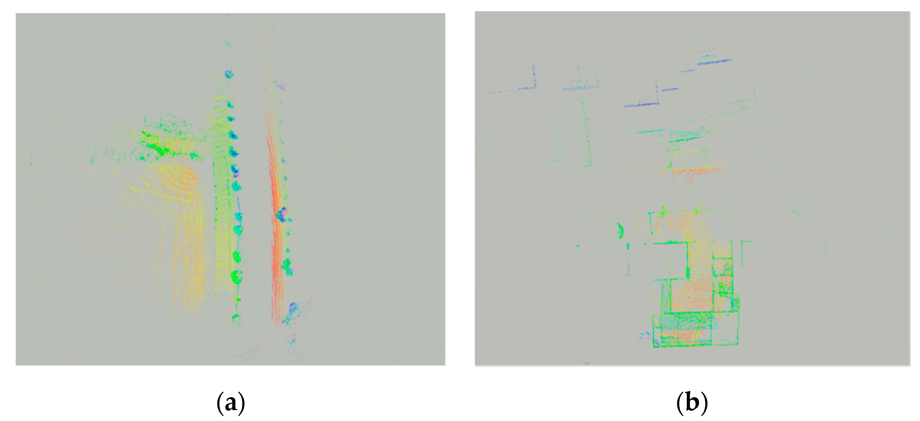
Figure 9 and
Figure 10 display the point cloud maps of the machinery sheds and farm access roads environments generated by the original and improved LeGO-LOAM algorithms, respectively. As shown in the figures, in the machinery shed environments, the point cloud map generated by the enhanced LeGO-LOAM algorithm exhibits clearer structural features. The improved algorithm achieves effective representation of both shed and access road environments using fewer points, thereby increasing both mapping accuracy and computational efficiency in these agricultural settings. In the farm access roads environments, the point cloud map produced by the original algorithm exhibits noticeable distortion, erroneously representing a straight path as a curved one. In contrast, the map constructed using the improved algorithm accurately reflects the actual geometry of the farm access roads.
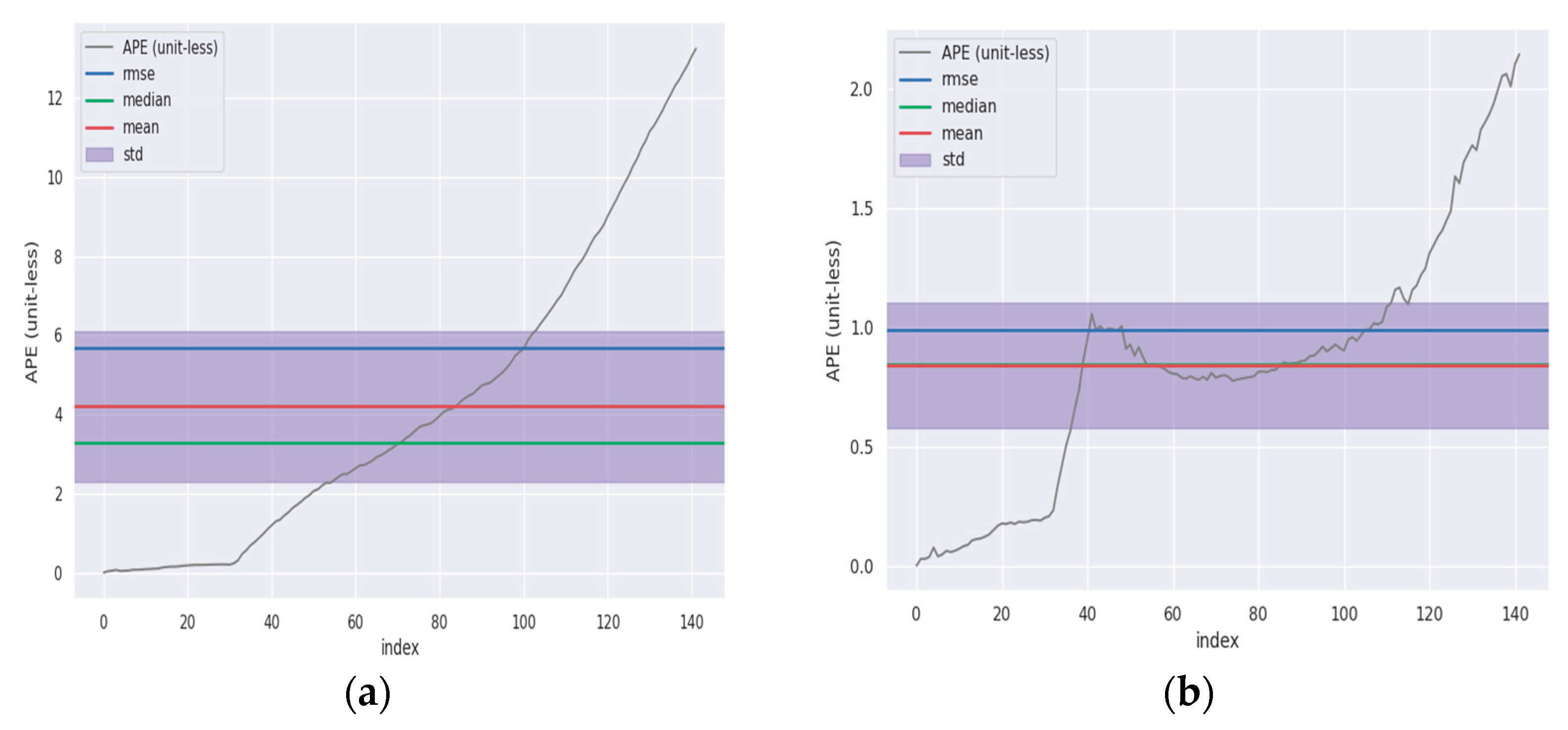
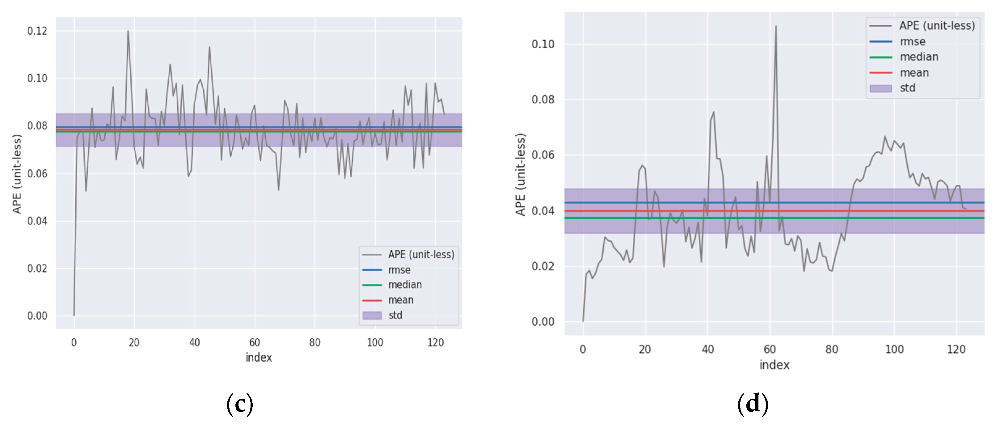
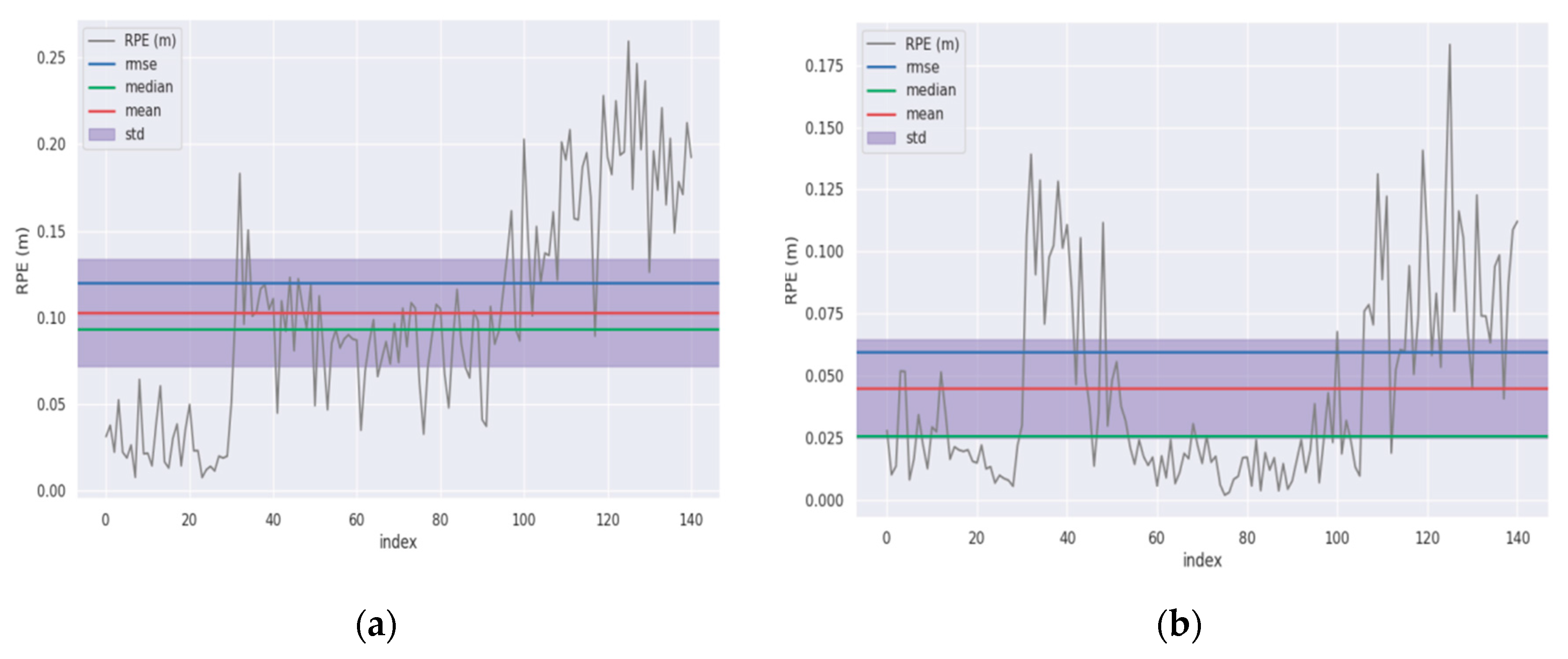
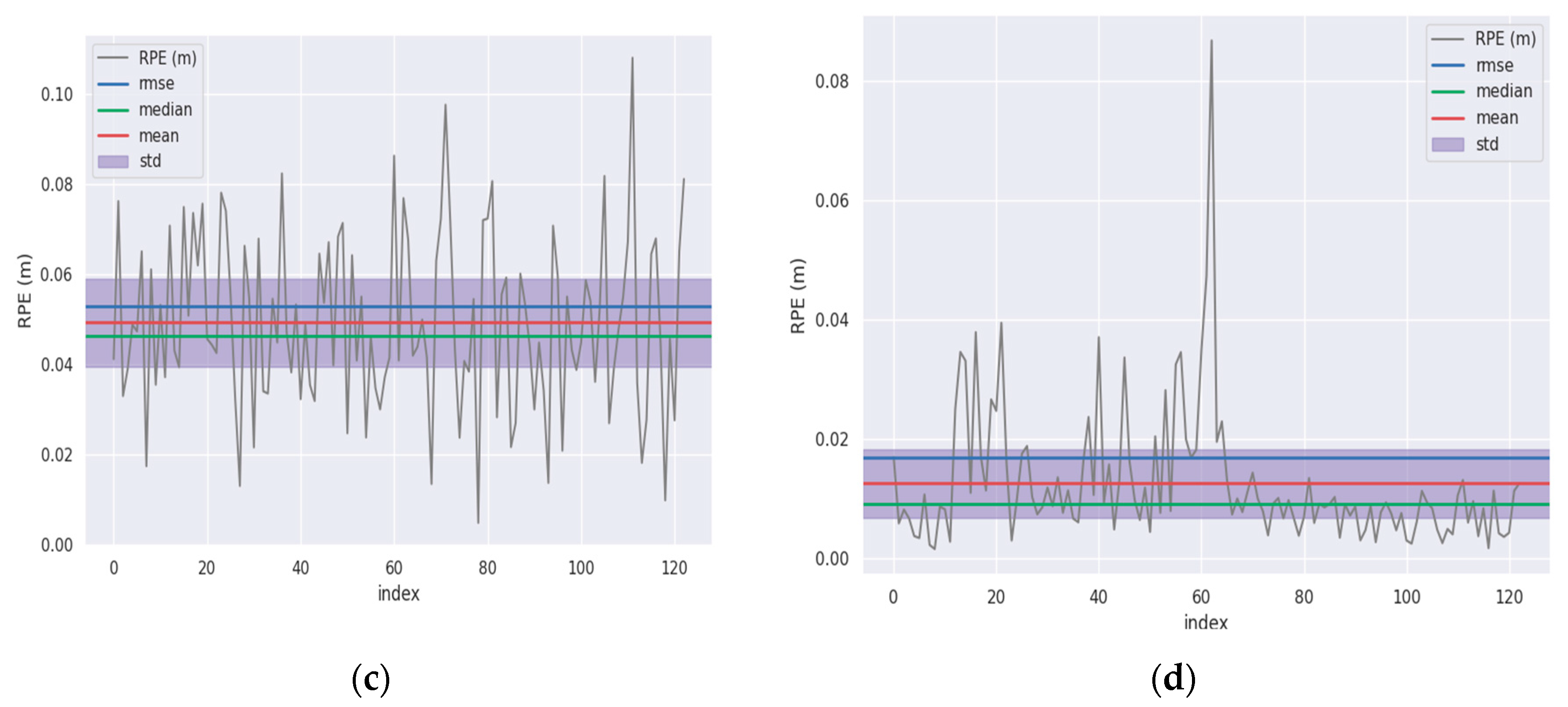
This paper employs two evaluation metrics, namely absolute pose error (APE) and relative pose error (RPE), to quantitatively assess the mapping accuracy of the LeGO-LOAM algorithm before and after improvement. APE measures the direct difference between the estimated pose and the ground truth pose, providing an intuitive indication of the algorithm’s precision and global trajectory consistency. RPE, on the other hand, evaluates the accuracy of the pose difference between two frames separated by a fixed time interval, reflecting local accuracy and consistency. Through multiple rounds of point cloud data collection experiments, we set the confidence intervals for APE and RPE to [0, 14] and [0, 0.3], respectively. Data falling outside these intervals were automatically filtered out.
As shown in
Figure 11a–d, the APE variations in the original and improved LeGO-LOAM algorithms in the machinery sheds and farm access roads environments are presented, respectively. By comparing the vertical coordinate values in the figures, it can be observed that the APE values of the improved algorithm are significantly reduced. According to the data in
Table 1, the decrease in APE achieved by the improved algorithm is notably substantial in both the machinery sheds and farm access roads environments.
As shown in
Table 1, the improved algorithm demonstrates significant error reduction in APE: the maximum error was reduced by 83.82%, the mean error by 79.99%, the median error by 74.25%, the RMSE by 82.54%, and the standard error by 86.29%. In the shed environment, the APE of the improved algorithm show marked decrease.
As shown in
Figure 12a–d, the variations in the RPE for the original and improved LeGO-LOAM algorithms in the machinery sheds and farm access roads environments are presented, respectively. From the vertical axis values in the figures, it is evident that the RPE values of the improved algorithm exhibit a significant reduction. This conclusion is further evidenced more intuitively by the comparative data provided in
Table 2.
As presented in
Table 2, the improved algorithm also achieves substantial reduction in RPE: the maximum error decreased by 29.35%, the mean error by 56.29%, the median error by 72.51%, the minimum error by 75%, the RMSE by 50.13%, and the standard error by 36.25%. In the shed environment, the RPE of the improved algorithm is significantly lower.
In both the agricultural machinery sheds and farm access roads environments, the improved algorithm demonstrates a significant reduction in both APE and RPE compared to the original LeGO-LOAM algorithm. This indicates that the proposed improvements enhance the accuracy of localization estimation, effectively mitigate accumulated errors during the mapping process, and produce a globally consistent point cloud map. As a result, the point cloud maps generated by the enhanced algorithm in agricultural environments exhibit high precision and faithfully represent the scene characteristics.
In summary, based on comprehensive experimental analysis, the improved LeGO-LOAM algorithm proposed in this paper substantially enhances mapping performance in both machinery sheds and farm access road environments, effectively meeting the requirements for high-quality mapping in such agricultural settings.
3.2. Localization Testing
To evaluate the performance of the proposed fused localization approach based on the UKF algorithm, validation experiments were conducted in which the localization results from both the NDT algorithm and the proposed fused method were recorded. GNSS measurement data were used as the ground truth trajectory to compare the localization errors of the two approaches.
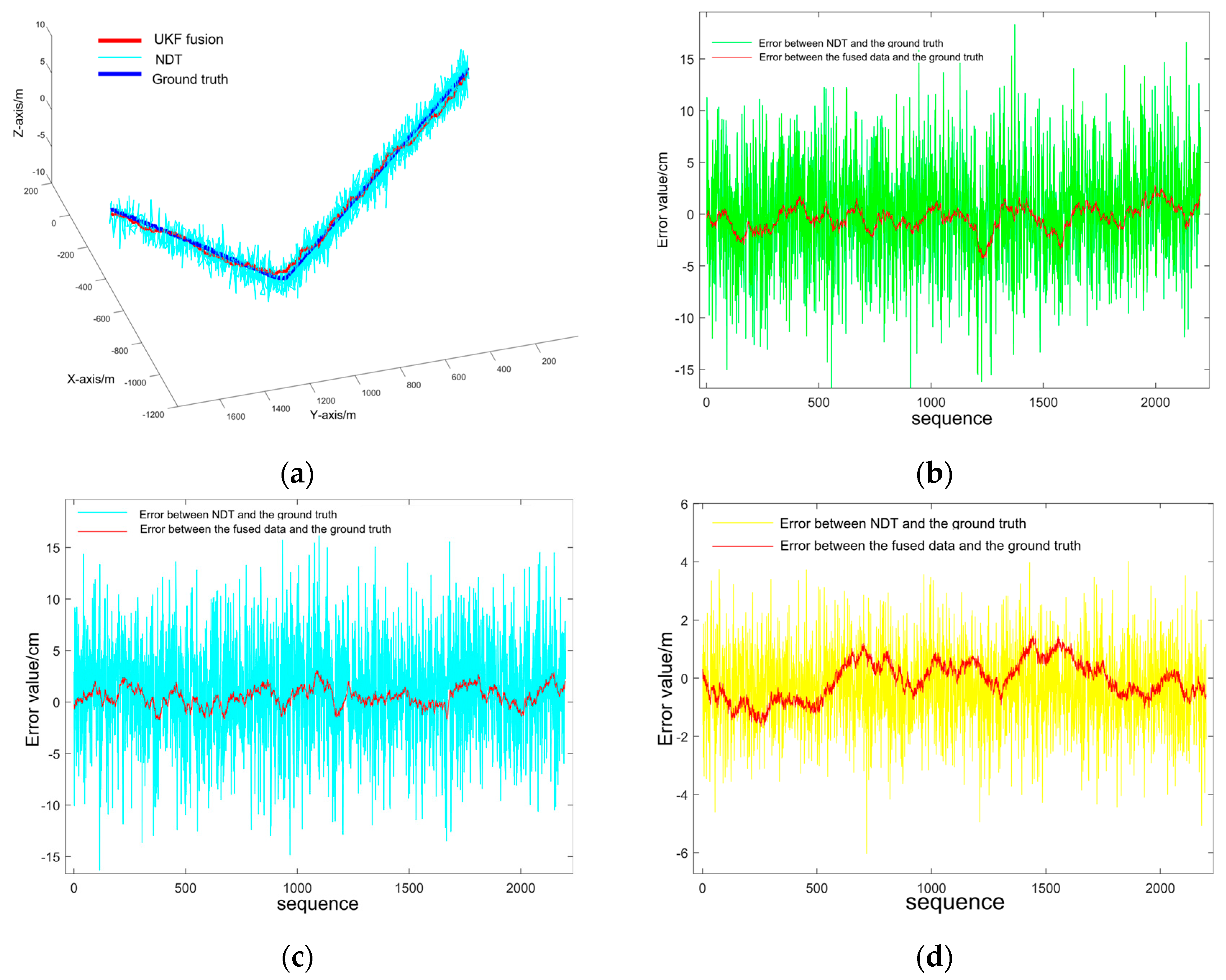
As shown in
Figure 13a, a comparison is presented among the localization trajectory estimated by the NDT algorithm, the trajectory obtained by the proposed fused localization method, and the ground truth trajectory. It can be observed that the trajectory of the proposed fused localization algorithm is closer to the ground truth.
Figure 13b–d, respectively, show the errors in the X, Y, and Z directions between the trajectories before and after fusion and the ground truth trajectory. The results indicate that the fused trajectory exhibits smaller errors in both the X and Y directions, reflecting the actual vehicle movement more accurately. In the Z direction, due to the inherent limitation of the NDT algorithm in estimating vertical localization, a significant reduction in error is achieved after applying the fusion algorithm.
To quantitatively compare the localization performance between the NDT algorithm and the proposed fused method, five sets of comparative experiments were conducted. The computational time and absolute localization error of both algorithms were recorded, as summarized in
Table 3.
From the data in
Table 3, it can be concluded that the average localization time across the five sets of fused localization experiments is 26.49 ms, and the average absolute localization error is 3.97 cm. The results demonstrate that the localization estimated by the UKF-based fusion algorithm achieves higher localization accuracy compared to the NDT localization algorithm, without significantly increasing computational time. The fused localization estimation method satisfies both the accuracy and real-time requirements for autonomous navigation of the grain transport vehicle.
To evaluate the impact of different travel speeds of the grain transport vehicle on the proposed fused localization algorithm, six sets of localization data collection experiments were conducted. The average vehicle speeds were set to 0.8 m/s, 1.2 m/s, and 1.5 m/s, with two experimental trials performed at each speed level.
As can be seen from the data in
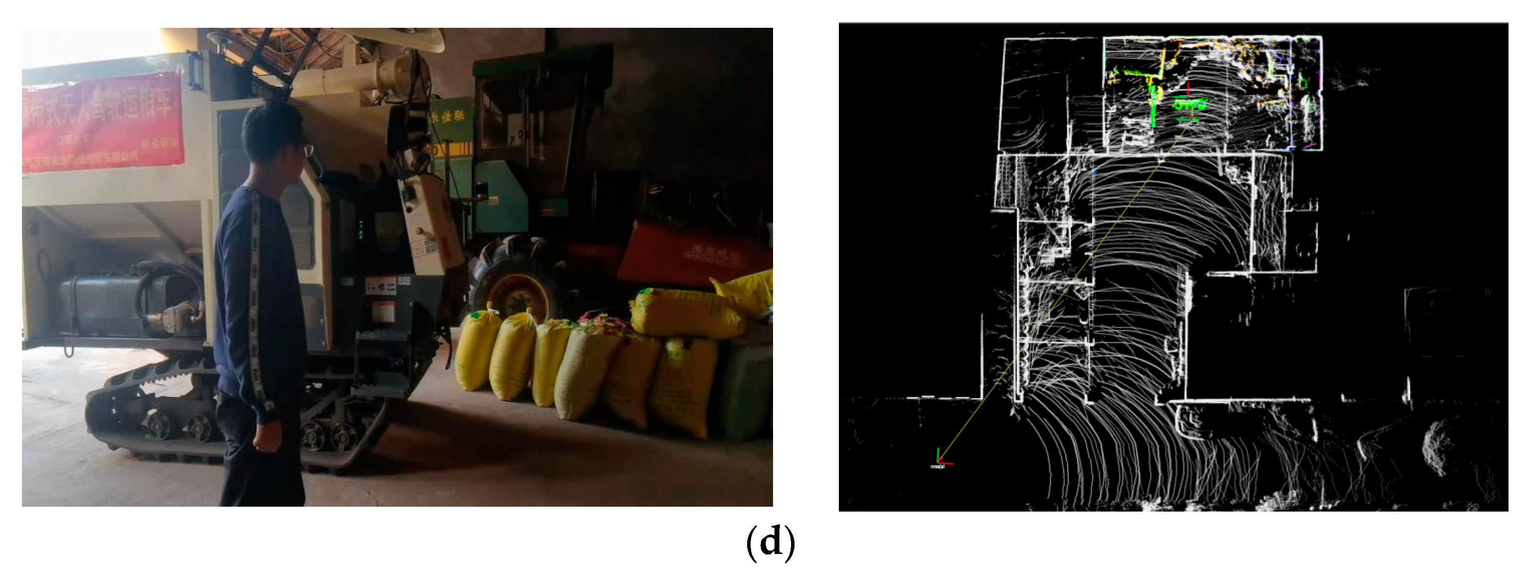
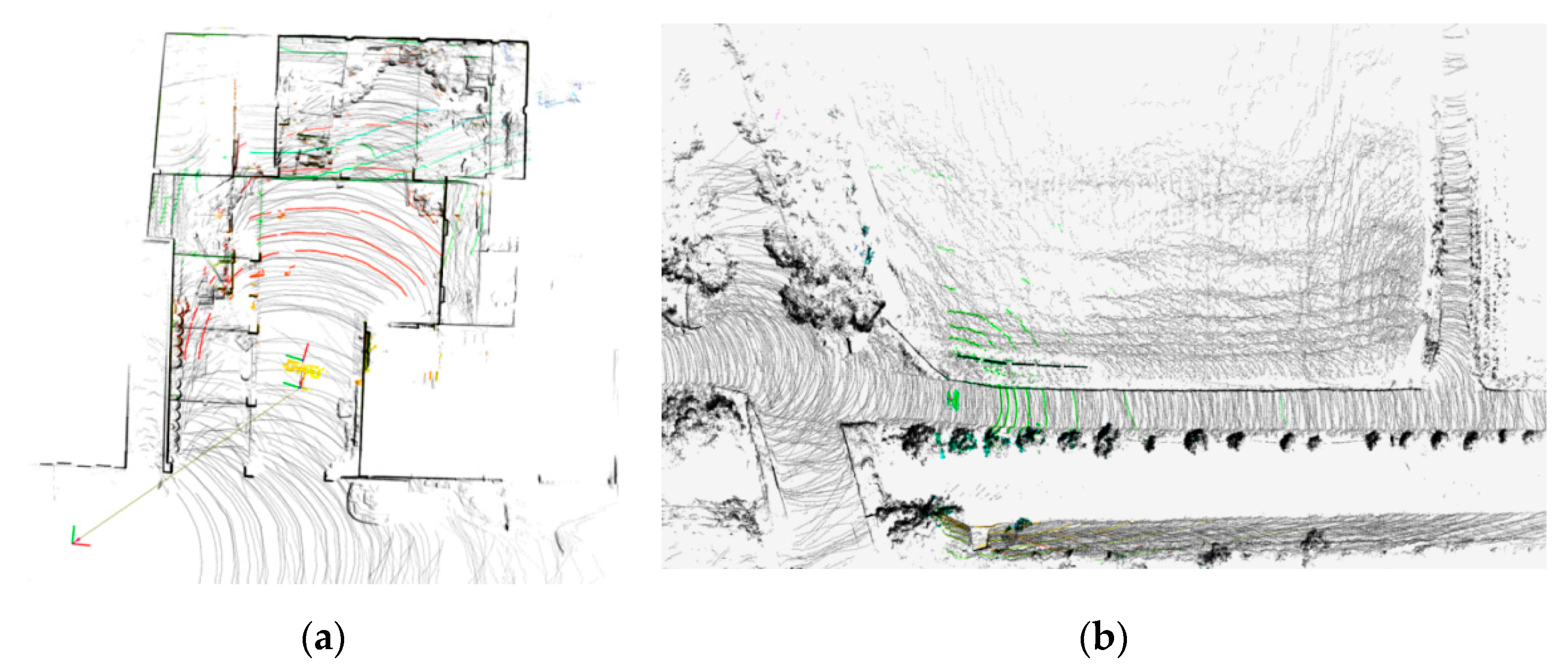
Table 4, the average localization time of the grain transport vehicle in the machinery sheds is 23.33 ms, with an average localization error of 4.226 cm.
Figure 14a shows a snapshot of the localization performance during the shed entry phase, where the TF coordinate frame visualizes the vehicle’s localization. In the farm access roads environments, the average localization time under three different speed settings is 28.56 ms, with an average absolute localization error of 5.215 cm.
Figure 14b illustrates the localization effect at a certain moment in the farm access roads environment, with the TF coordinate frame indicating the vehicle’s localization. In both environments, the localization speed and accuracy of the navigation system meet the requirements for autonomous operation.
