Article

Wear Calculation Method of Tripping Mechanism of Knotter Based on Rigid–Flexible Coupling Dynamic Model

1
School of Agricultural Engineering, Jiangsu University, Zhenjiang 212013, China
2
Heilongjiang Academy of Agricultural Machinery Engineering Sciences, Haerbin 150081, China
*
Author to whom correspondence should be addressed.
Agriculture 2025, 15(21), 2229; https://doi.org/10.3390/agriculture15212229 (registering DOI)
Submission received: 22 September 2025 / Revised: 20 October 2025 / Accepted: 22 October 2025 / Published: 25 October 2025
(This article belongs to the Section Agricultural Technology)

Abstract

Targeting the problem of lack of theoretical model for wear calculation of key actuators in the knotter, a tripping mechanism of knotter based on the principle of elastic deformation was designed. A rigid–flexible coupling dynamic analysis model of the tripping mechanism was established based on the modal stress method, and the contact force time history curves and dynamic stress results between the groove cam and the ball roller, as well as between the knotter jaw and the tripping plate slot, were simulated. Based on MSC, Marc MENTAT, a finite element wear calculation model of the tripping mechanism, was constructed. Through 600 simulations equivalent to 6000 working cycles, the wear cloud maps of the tripping plate and the large gear groove cam were obtained, and the key wear areas and expansion trends were analyzed. The rapid wear tests were conducted by using a self-made knotter fatigue wear test bench, which showed that the maximum deviation between the measured value and the simulated value of the contact pair wear was less than 10%. This verified that the proposed wear model for the tripping mechanism can be used for calculating the contact pair wear of the mechanism, providing a reference for the heat treatment process of the surface hardness of the parts.

1. Introduction

With the increasing demand for straw feed utilization and the gradual expansion of high-quality forage planting areas, as the core component of high-density bundling forage, the reliability of the technology of knotters has always been a hot research and development field in the animal husbandry industry [1,2,3,4]. The tripping mechanism is one of the key executing components of the knotter. The contact form between the spherical roller at the end of the knife arm and the groove cam of the gear plate is point contact, and the contact form between the tripping plate slot at the lower end of the knife arm and the bottom of the knotter jaw is line contact with interference fit. Both types of contact have problems such as large impact, stress concentration, and fast wear. Li et al. [5] improved the existing tripping mechanism and conducted related research on the relationship between the knife angle and the rope-cutting force. Xiong et al. [6] elasticized the knotted nozzle shaft system to reduce the impact during tripping according to the principle of hard-and-soft collision. Li et al. [7] improved the profile of the gear groove cam of the tripping mechanism to reduce the wear of the cam. Lv et al. [8] put forward a scheme of replacing the existing point contact planar cam profile with a line contact curved cam mechanism with sinusoidal acceleration of the driven component; the simulated predicted values of cam wear before and after improvement were compared and analyzed, and experimental verification was carried out. The above research works have played a certain reference and promoting role in the study of fatigue life and wear of tripping institutions.
As we all know, wear is a dynamic coupling process of friction accumulation. To obtain the wear amount under the contact times of a part, it is necessary to continuously update the contact part morphology and calculate the contact pressure of the part under the current contact morphology to achieve iterative prediction [9,10]. There is a practice of iterative wear simulation of motion pairs using finite element software such as Abaqus, ANSYS, and MSC. Marc is becoming increasingly common by establishing wear simulation models. Kunal et al. [11] used Abaqus to successfully simulate the wear model of the pin disc, and Wang et al. [12] dynamically simulated the effect of load on the wear of U-shaped rings in Abaqus based on the Archard wear model. Takeuchi et al. [13] used Marc to perform numerical calculations on the wear of the mooring line hinge pair of the floating body, and the calculated wear values were generally close to the actual wear measurement results. Based on the Archard wear model, Hou et al. [14] conducted finite element simulation of the disengagement and jamming process of the finger lock using HyperMash meshing and MSC. Marc solution and obtained experimental results such as stress and wear rate were not easily obtained. Zhang et al. [15] further optimized this numerical calculation model, developed the dynamic subroutine VFRIC in Abaqus based on the theory of friction energy density rate, and calculated the visualization distribution of the friction energy density rate area of the finger lock chuck contact.
This article addresses the issue that there is a lack of theoretical models for calculating the wear of key transmission components in knotters. Subsequently, a tripping mechanism for knotters based on the principle of elastic deformation is proposed, which is identified as the research focus of this study. Section 2 elaborates on the design of the tripping mechanism based on the principle of elastic deformation. In Section 3, by establishing a rigid–flexible coupling dynamic model of the tripping mechanism using the modal stress method, the contact force time–history curves and dynamic stresses of the tripping mechanism were obtained. Section 4 calculates the wear volume of key contact pairs based on the Archard wear model. In Section 5, rapid wear tests are conducted to verify the calculation accuracy of the proposed wear model for the tripping mechanism. Section 6 presents the conclusions: the proposed wear model for the tripping mechanism is applicable to wear calculation of the mechanism’s contact pairs, and provides a reference for the heat treatment process aimed at optimizing the surface hardness of components.

2. Design of the Tripping Mechanism Based on the Principle of Elastic Deformation

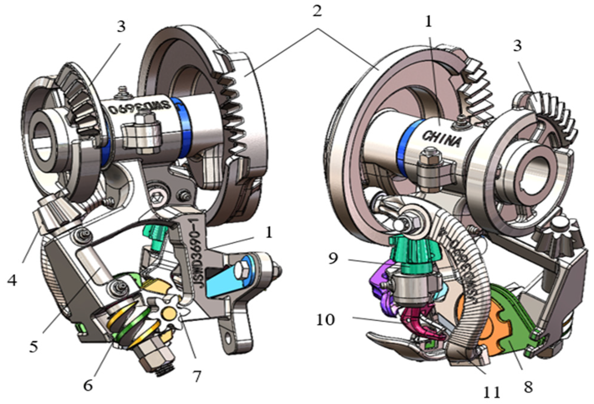
To improve the success rate of tripping, a tripping mechanism in the knotter based on the principle of elastic deformation was designed, which consists of a groove cam on a large fluted plate and a split type of knife arm installed on the knotter bracket. It is a space orthogonal disc-shaped cam mechanism with a roller swinging follower, as shown in Figure 1. The large fluted plate is fixed and rotated with the knotter spindle, and the inner contour of the groove cam moves relative to the roller in contact with it, forming a cam contact pair. The knife arm swings around its axis direction, and through the interference contact between the arc-shaped groove surface of the knife arm and the bottom arc-shaped surface of the knotter jaw; the knot wrapped around the knotter jaw is forcibly removed by the knife arm. Therefore, when the groove of the tripping block comes into contact with the bottom surface of the knotter jaw, the arc-shaped line contact at the contact pair has a large contact force, causing wear on the contact pair and significant elastic deformation of the knife arm.
As shown in Figure 1, by utilizing the large displacement elastic deformation of the knife arm body, the knife arm was designed as a modular combination structure. A tripping block is installed on the knife arm body, and the knife arm body and the tripping block can be manufactured using different materials and heat treatment processes, respectively, ensuring the fatigue strength of the knife arm while also meeting the requirements of wear resistance of the tripping block. When the contact pair formed between the tripping block and the bottom surface of the knotter jaw wears out beyond the magnitude of tripping interference, which is equal to elastic deformation of the knife arm, the adjusting shims can be added to compensate for the wear of the tripping block and the bottom surface of the knotter jaw, keeping the magnitude of tripping interference in the appropriate range to solve the tripping fault.
The designed tripping mechanism is assembled onto the knotter to form the knotter driven by double fluted discs with the same tooth trace, as shown in Figure 2.

3. Simulation of the Tripping Mechanism Based on Rigid–Flexible Coupling Dynamic Model

3.1. Pre-Processing of Finite Element Model of the Tripping Mechanism Parts

Considering the limited geometric modelling capabilities of finite element software, HyperMesh 2021 software was used to perform geometric structure processing and topological optimization of the CAD model of the tripping mechanism, and establish a finite element mesh model, which was convenient for importing into finite element software for solution calculation [16,17,18]. At this point, the established model will be used for a series of simulations in the future. In order to simplify the subsequent process, the material properties of each part will be assigned together, as shown in Table 1. In addition, after measuring the static friction coefficient between each part by using the inclined surface tester, their static friction coefficients were set to 0.36, and the coefficient of kinetic friction is 0.1.

3.2. Construction of Rigid–Flexible Dynamic Model of the Tripping Mechanism

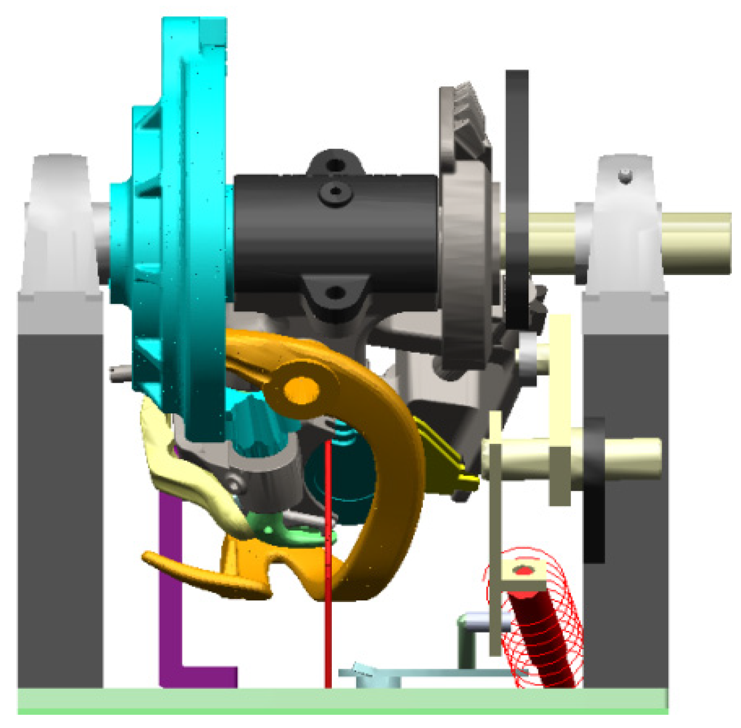
Considering factors such as the large deformation of the knife arm, the fixed interface modal synthesis method, also known as the Craig Bampton method [19,20], was used to establish a rigid–flexible-coupled multi-body dynamic model of the tripping mechanism. According to the actual deformation of each contact pair in the tripping mechanism, the groove cam on the large fluted disc was set as flexible bodies, and the ball roller was considered as rigid bodies. In the arc-shaped line contact pair composed of the tripping block and knotter jaw, the knife arm and tripping block were set as flexible bodies, and the knotter jaw was set as rigid bodies. According to the actual constraint situation, the Opti Struct solver was used to calculate the constraint modes of the parts, and the modes were superimposed to generate MNF files for import into ADAMS, which completed the flexibility of the key parts and obtained the rigid–flexible-coupled multi-body dynamic model shown in Figure 3.
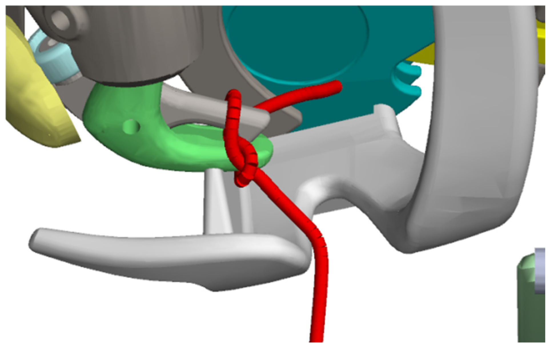
According to the motion law of each motion component, each motion pair was added to each component. At the same time, by using the Bushing connection in ADAMS, multiple rigid cylindrical bodies were connected to simulate rope-tying, as shown in Figure 4. By setting multiple contact constraints and applying loads, virtual knotting can be achieved more accurately, and the loading on parts such as the knotter jaw and tripping block can be simulated [21].

3.3. Solution of Rigid–Flexible Coupling Dynamic Model

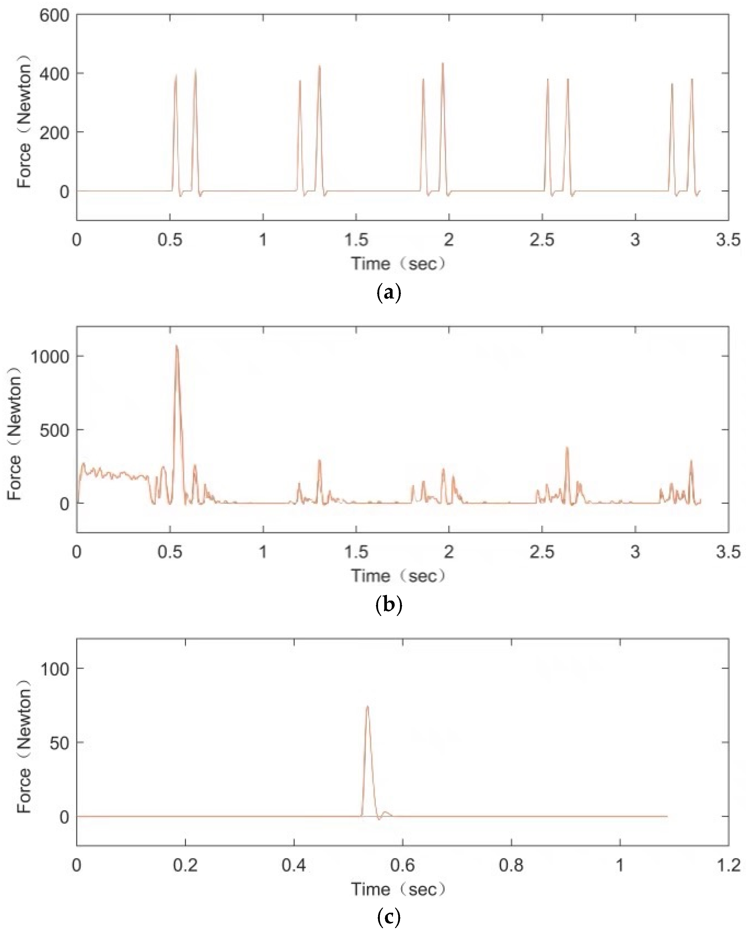
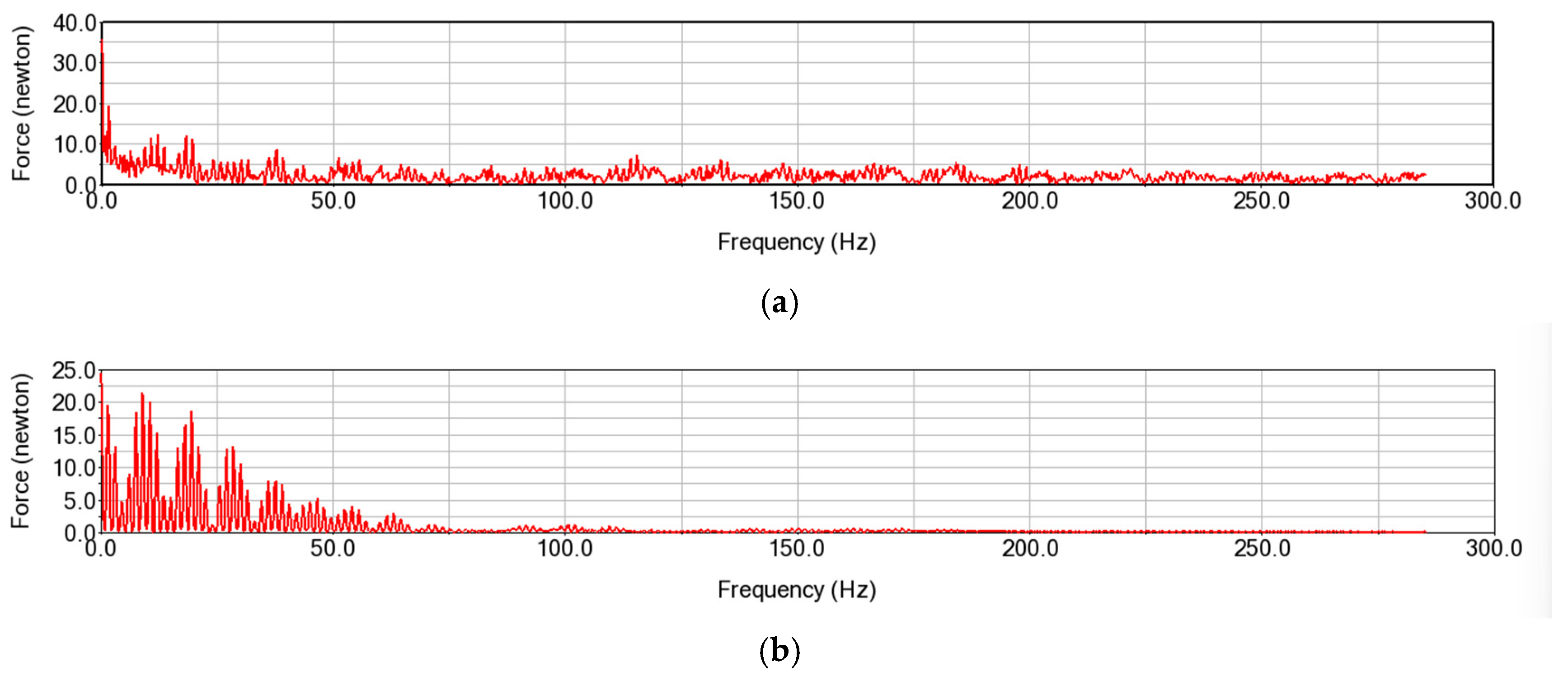
The drive and motion pair constraints were added to the rigid–flexible coupling dynamic model of the tripping mechanism, and the flexible parts were connected to other components through defined external connection points. When setting up contacts, the contact type titled with Flex Body to Solid should be selected between flexible and rigid parts. Based on a comprehensive comparison of simulation time and computational accuracy, the GSTIFF SI2 solver was chosen. During simulation calculation, the spindle speed of the knotter was set to 90 revolutions per minute, the simulation time was set to 3.5 s, and the number of steps was 500. The load time–history curves of the contact parts were obtained through ADAMS rigid–flexible coupling dynamic simulation, as shown in Figure 5. Additionally, the fast Fourier transforms (FFTs) of the power density spectrum of the contact force between the ball roller and the grooved cam on the large fluted disc, and between the tripping block and the knotter jaw, were derived, as shown in Figure 6.
By reading the data points from ADAMS rigid–flexible coupling dynamics simulation results, the peak loads at each contact pair were obtained. At the moment of tripping, the peak loads among the tripping block and the knotter jaw, ball roller and the grooved cam on the large fluted disc, and the tripping block and the simulating rope were 435.42, 1069.61, and 74.55 Newton, respectively. At the moment of reset, the peak loads between the tripping block and the knotter jaw, and ball roller and the grooved cam on the large fluted disc were 424.54 and 258.09 Newton.
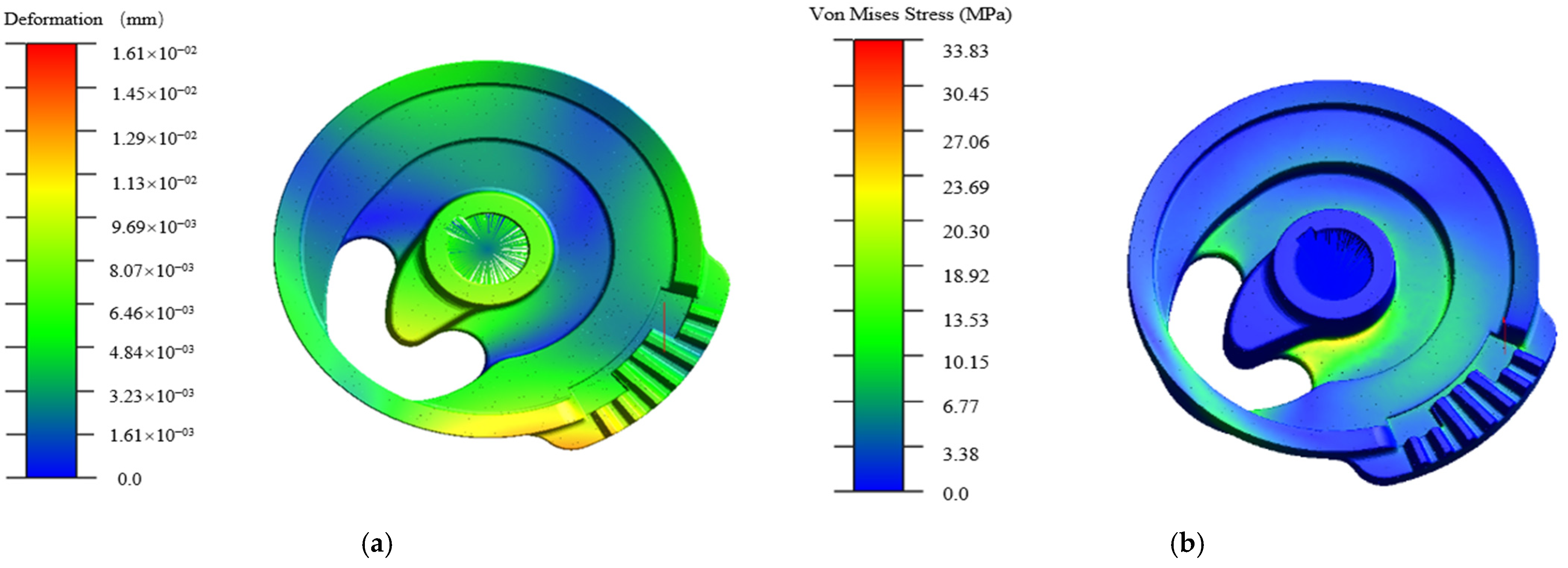
FFT analysis reveals that the primary energy distribution frequency of the contact force falls within the range of 0–50 Hz. To clearly observe the force-induced deformation characteristics of the components under this working condition, the deformation and stress contour plots of the knife arm and the large fluted disc are presented below, as illustrated in Figure 7 and Figure 8, respectively.
According to the hot spot table provided by the ADAMS Durability module, the maximum stress of the knife arm occurs at the moment of tripping; its deformation contour and stress contour are shown in Figure 7a and Figure 7b, respectively.
For the hot spot table of the large fluted disc, the stress distribution is relatively uniform. It was found that the maximum stress point appears at the junction of the hub and the groove at the moment when the cutter arm returns to its original position and reaches the peak load, with its deformation contour and stress contour shown in Figure 8a and Figure 8b, respectively.
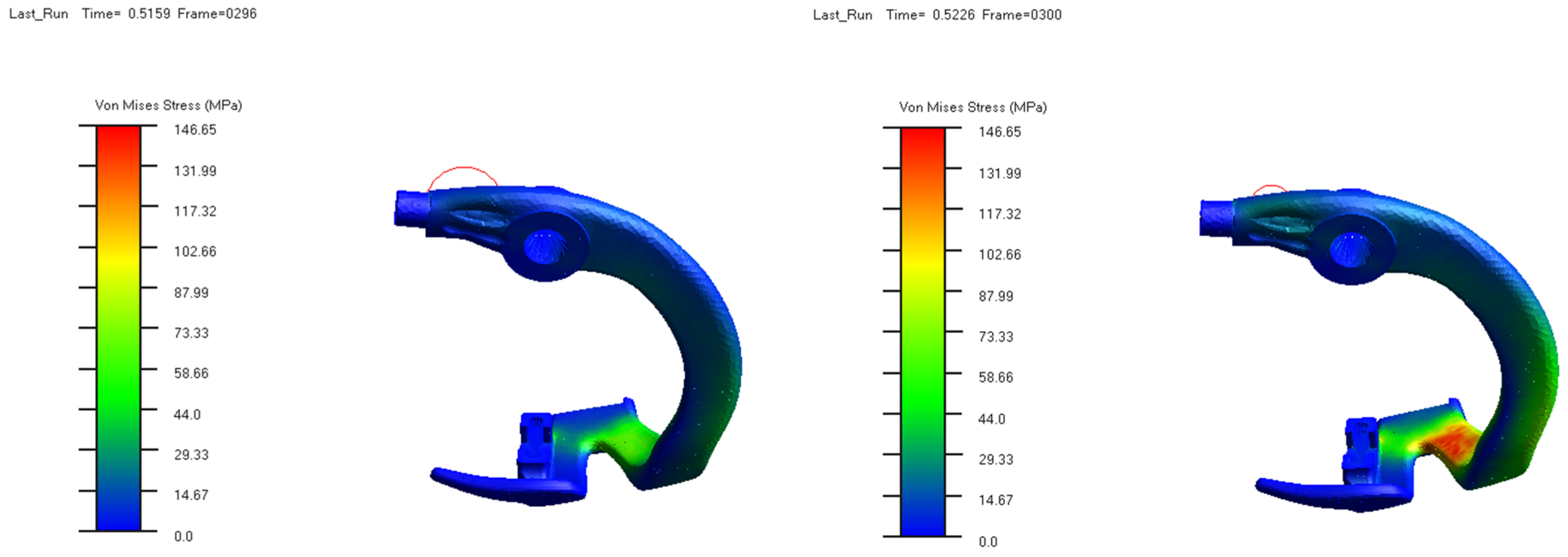
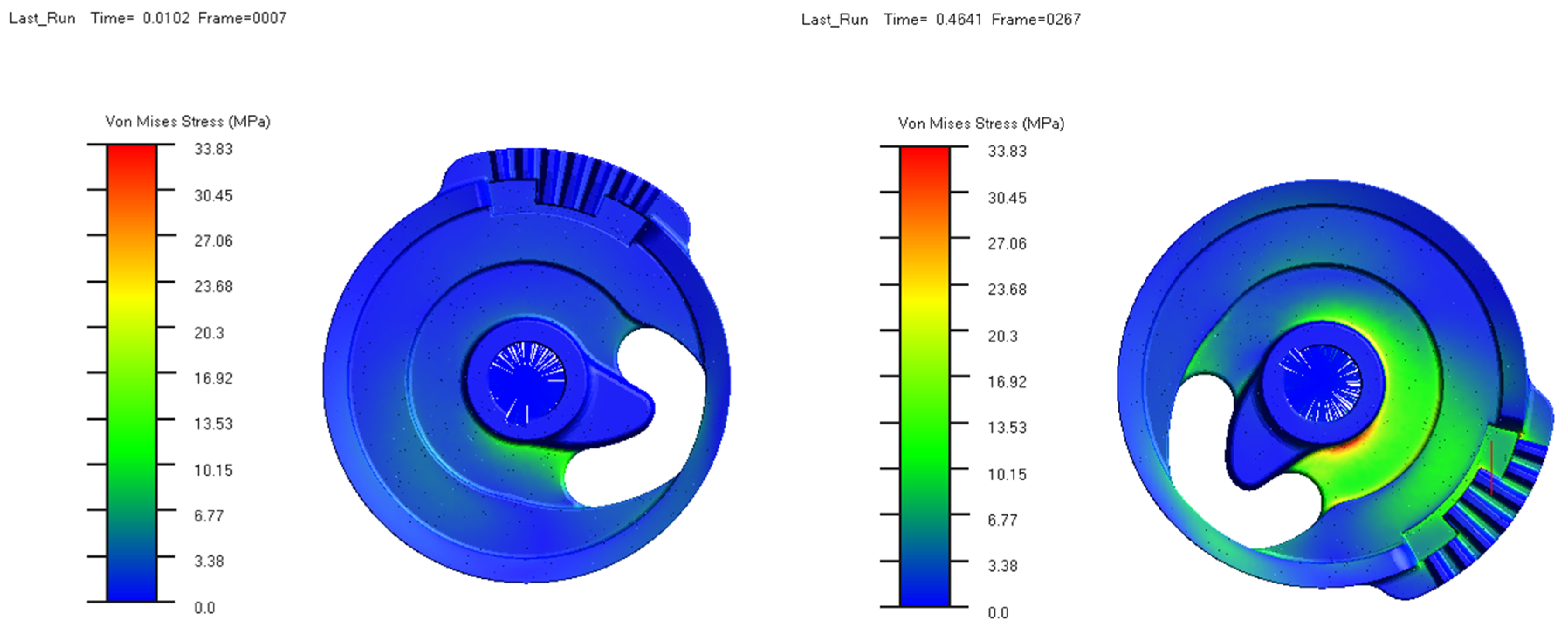
In a motion simulation, the stress contours of the knife arm and the large toothed disc were randomly captured, as shown in Figure 9 and Figure 10, respectively.

4. Wear Calculation and Prediction of Tripping Mechanism

4.1. Constitutive Model of Wear

The Archard wear model [22], which has been verified and applied in many fields, was used to simulate the wear of the tripping mechanism based on the finite element method. Based on classical elastic–plastic deformation theory of materials, the Archard model mainly established a functional relationship between the wear amount and normal load, and its form may be expressed as follows:
V = K N L H
Among them, V is the volume of abrasive particles, L is the sliding distance, N is the contact load, and H is the hardness of the abrasive. K is a dimensionless wear parameter, and may be regarded as a typical probability factor of abrasive particles appearing in the grinding of composite materials. For the tripping mechanism, there is no lubrication in each contact area. Based on the literature review [23], it was determined that the K value for the cam contact pair is 10−6, and the K value for the contact between the tripping groove and the knotting jaw is 10−4.

4.2. Construction of Finite Element Wear Model

4.2.1. Establishment of Model

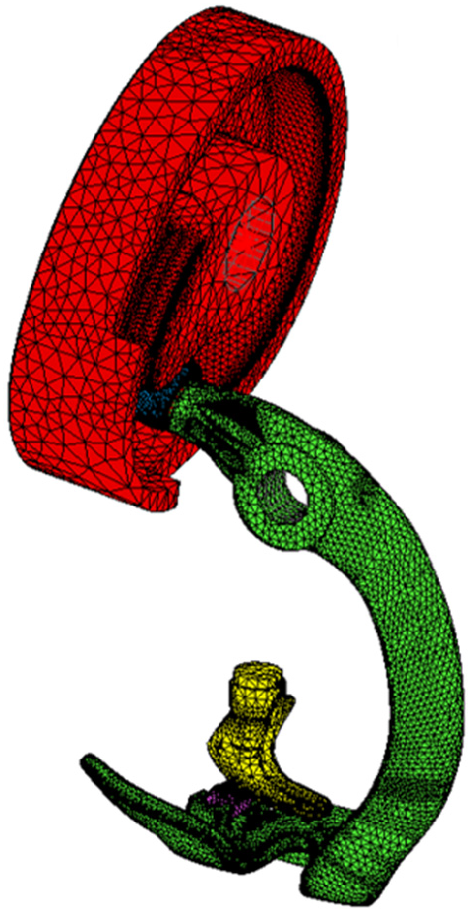
In order to reduce the calculation of wear, only the grooved cam was reserved for the structure of the large fluted disc. HyperMesh 2021 software has been used to mesh each part in Section 3.1. The mesh results can be directly imported into MSC.MARC 2020 with INP format. As shown in Figure 11, the contact bodies of meshed parts were established separately, and their hardness values were also added.
In order to verify the wear calculation method and reduce the testing time, only annealing treatment was performed on the castings of each component. The HRS-150 digital hardness tester was used to conduct routine hardness tests on the trial-produced large fluted disc, knot jaw, ball roller, and tripping plate, and their hardness values were 252.7, 253.4, 223.7, and 109.2 HBS, respectively.

4.2.2. Setting of Boundary Conditions and Contact

In the imported model, only five parts were included, namely the large fluted disc, ball roller, knife arm, tripping plate, and knotter jaw. When tripping, the knotter jaw was fixed, and the large fluted disc and knife arm rotated on a fixed axis, with node constraints on each axis hole. The absolute origin was defined as the centre of the knife arm shaft hole, and the rotation constraint of the knife arm was completed. The contacts between grooved cam and ball roller, and tripping plate and knottier jaw were defined as “surface-to-surface” contact.

4.2.3. Setting of Driving and Analysis Working Conditions

Based on the speed of 90 revolutions per minute used in the dynamic simulation, the total analysis time was set to 400 s, and the total analysis steps to 80,000 steps. The calculation cycle was set to 6000 times, and the driving of the tripping mechanism was set to rotate the large fluted disc with a total of 6000 revolutions. The static computing framework and Pardiso direct sparse matrix solver were adopted, with a displacement convergence criterion error of 10−4. The computing platform used a workstation equipped with Intel i7-12700K 12 core processor and 128 GB of memory.

4.3. Simulation Results and Analysis

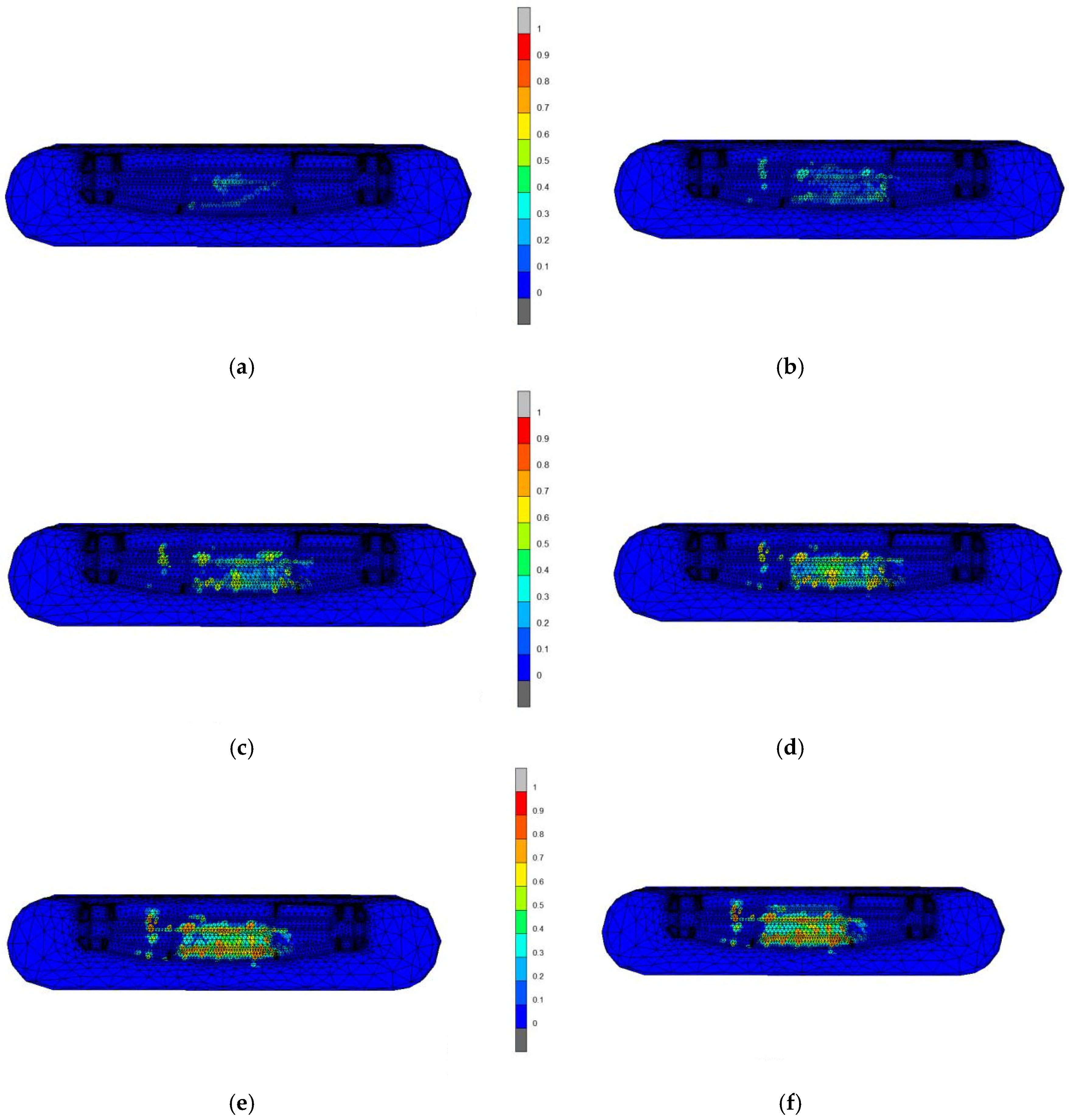
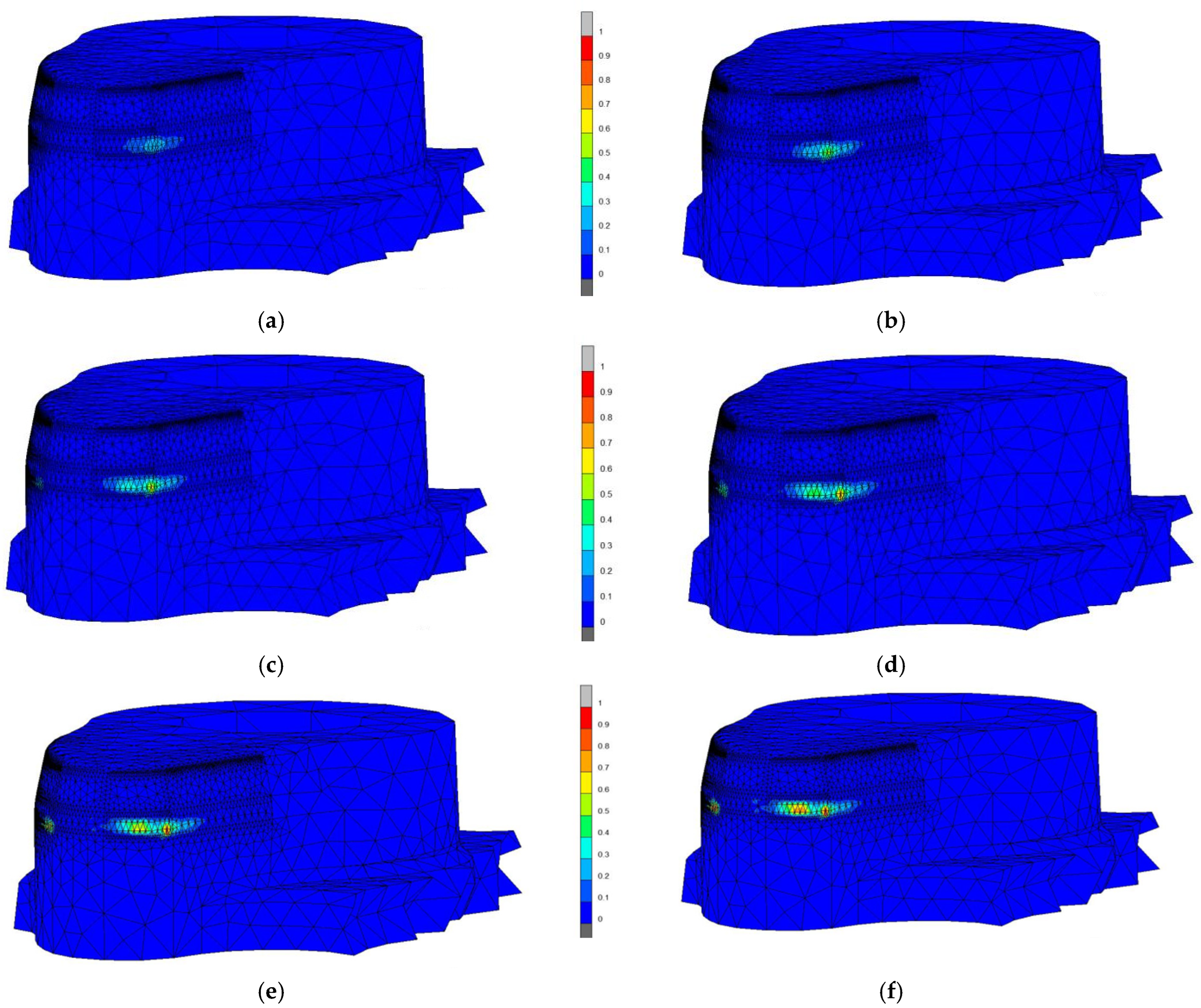
The total time for wear calculation was 168.2 h. Data analyses were conducted on the tripping plate with lower surface hardness and the cam part of the large fluted disc. Their wear cloud maps are shown in Figure 12 and Figure 13, respectively.
As seen from Figure 14, the wear of the tripping block mainly occurred on the tripping working surface, and the wear surface gradually expanded from the initial contact surface. From Figure 15, it can be seen that the wear of the large fluted disc occurred near the cam vertex, and its wear began at the driving point of the tripping action, which was consistent with the load peak point of the dynamic simulation. The wear index is a quantitative indicator that characterizes the anti-wear performance of materials, which can be expressed as the total amount of surface wear per unit. By post-processing of wear calculation, the wear results of the tripping block and grooved cam at different stages were statistically analyzed and their maximum wear amounts are shown in Table 2.
According to the data in Table 2, the wear of the tripping block showed an overall trend of first increasing and then decreasing. The wear increment became very small between 5000 and 6000 trips. This was because the contact between the tripping block and the knotter jaw gradually decreased until it disappeared as the amount of wear increased. After reviewing the wear increment process of the tripping block, it was found that the wear rate on the surface of the tripping block approached zero between 5320 and 5330 trips, indicating that the wear of the tripping block can be considered to end after about 5300 actual uses. Once the tripping block does not come into contact with the bottom surface of the knotter jaw, the tripping mechanism will fail to trip. For the grooved cam, as the number of trips increased, the wear amount of the outer surface contour of the groove cam gradually increased, but the wear increment became smaller and smaller.

5. Wear Model Verification of Tripping Mechanism

Due to the simplification of the wear model during simulation calculations and the difficulty in aligning boundary conditions with actual working conditions, wear tests need to be conducted on a test bench to observe the wear changes in the tripping mechanism after long-term operation of the knotter. The experimentally measured wear amount should be compared with the numerical calculation results to verify the accuracy of the wear calculation model.

5.1. Test Materials and Test Equipment

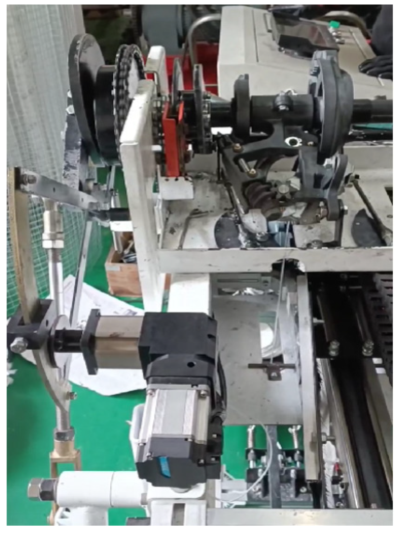
According to the working principle of the knotter, the trial-produced parts were fully assembled into a knotter, and it was installed on the self-made knotter wear test bench, as shown in Figure 14. The fast-knotting mode of the test bench was adopted, and the knotter was continuously knotting three knots per minute.

5.2. Wear Measurement and Result Analysis of the Tripping Mechanism

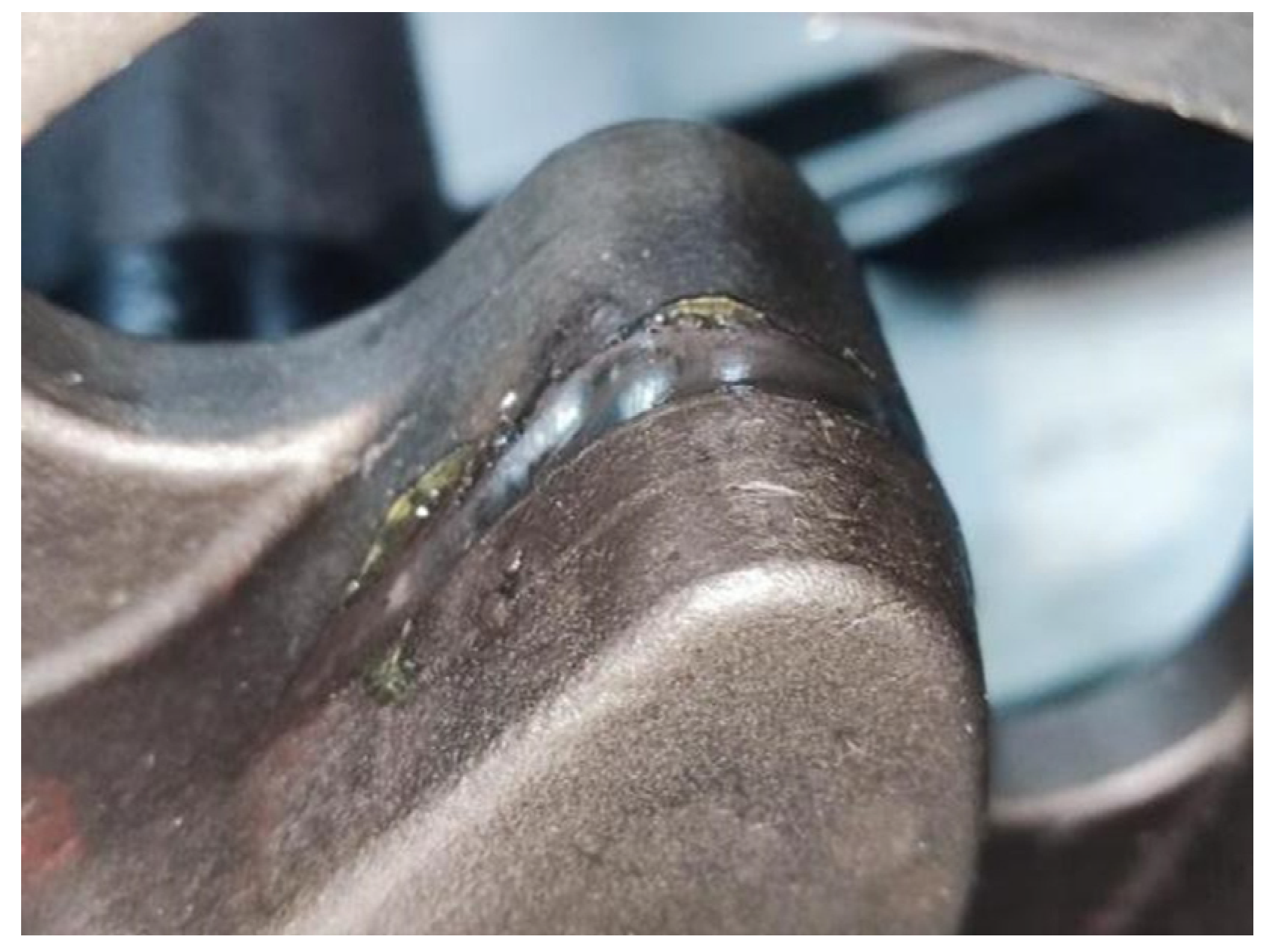
During the wear test, 1000 knots were divided into one set of tests. Before and after the experiment, a handheld 3D laser scanner was used to scan the cam contour of the large fluted disc and tripping block, and then their solid model was aligned and measured to obtain their wear amount. The 3D laser scanner used was an EXA scan product produced in Canada, and its point cloud accuracy reaches 0.04 mm. In the sixth experiment, it was observed that the wear of the tripping block no longer extended, and the contact area of the tripping block lost its sense of resistance. The wear state of the surface of the tripping block and the cam after the experiment of 6000 knots are shown in Figure 15 and Figure 16.
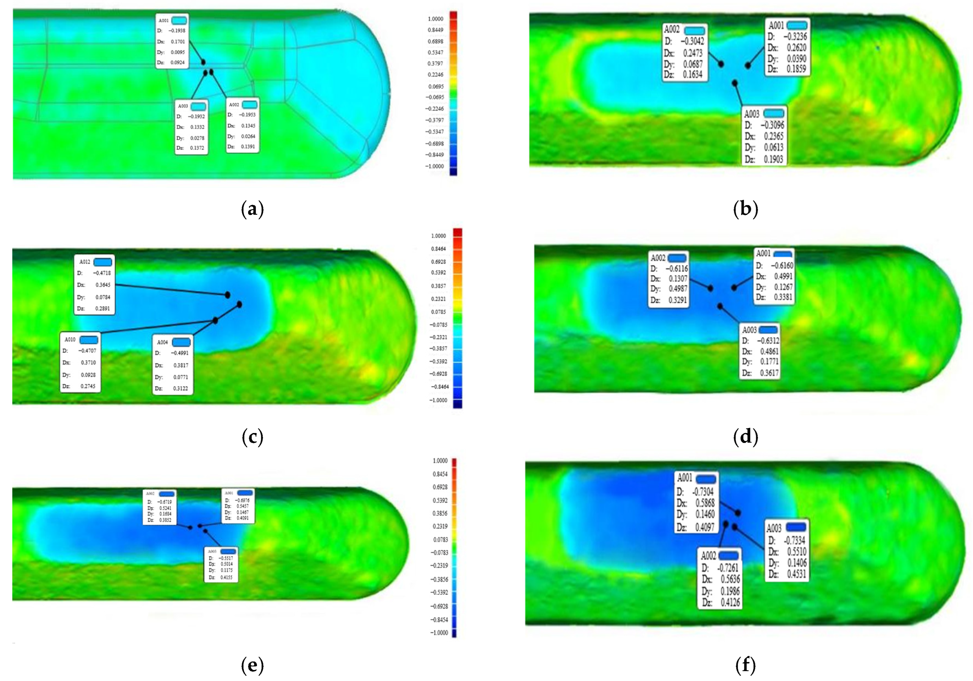
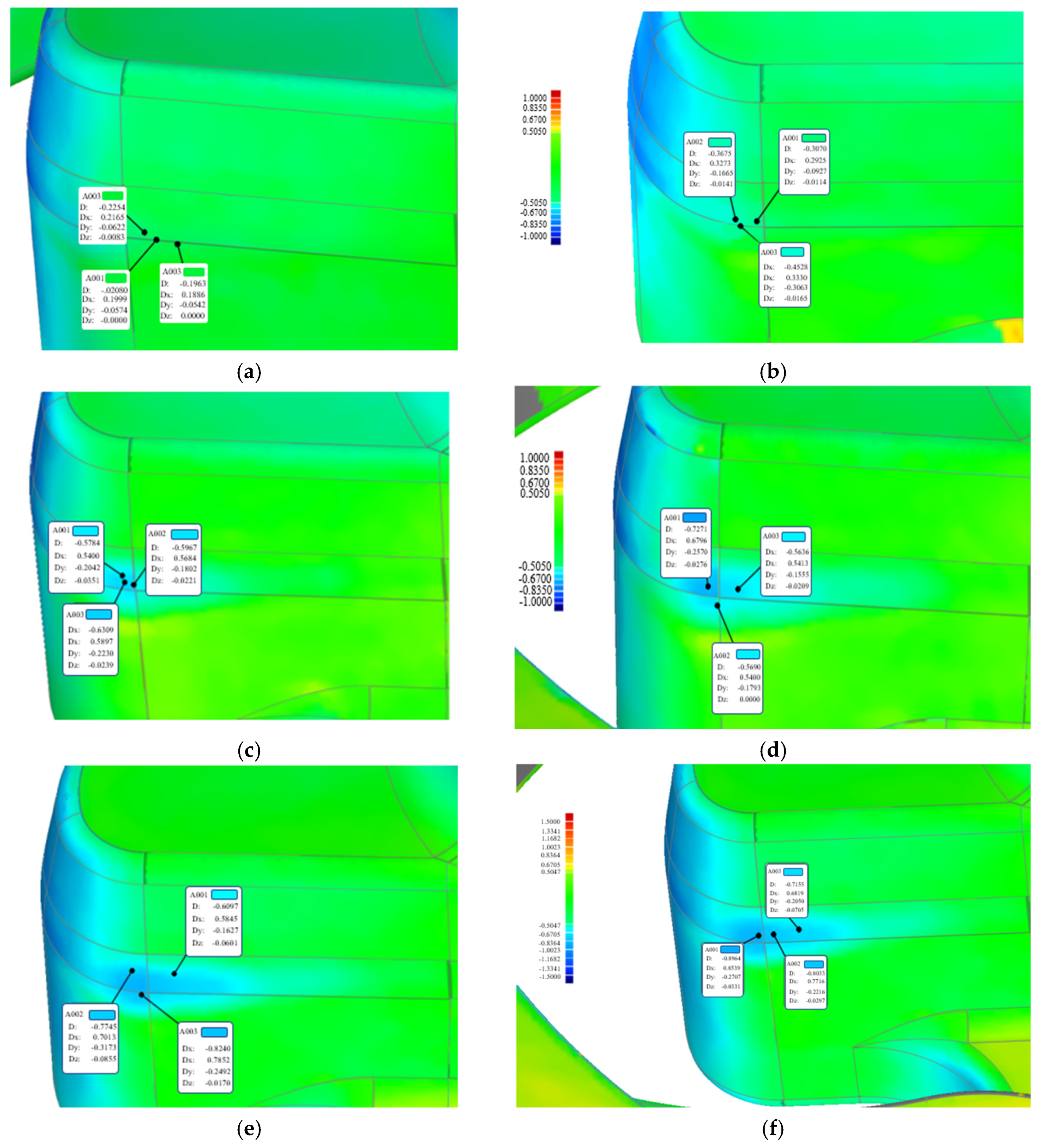
After obtaining the best fitting alignment between the solid model scanned before the experiment and the worn parts, the deviation analyses were carried out. Their wear amounts were obtained by multi-point measurement, as shown in Figure 17 and Figure 18.
By comparing the measured wear amount of the tripping block and cam contour with the simulation results, and the maximum deviation between the measured value and the simulation value should not exceed 10%. Considering the grid errors in simulation calculations and measurement errors in 3D laser scanning, it was considered that the calculation accuracy of the wear model with an error of 10% was acceptable. In addition, it was found that there was no contact between the tripping block and knotter jaw after 6000 trips, and the wear of the tripping block significantly decreased after 5000 trips, which verified the calculated results of the tripping block losing contact with the knotter jaw after about 5300 knotting cycles. The wear tests also showed that the simulation results of the wear model of the tripping mechanism were highly consistent with the experimental results.

5.3. Suggestions on Heat Treatment Process for Wear Resistance of Parts

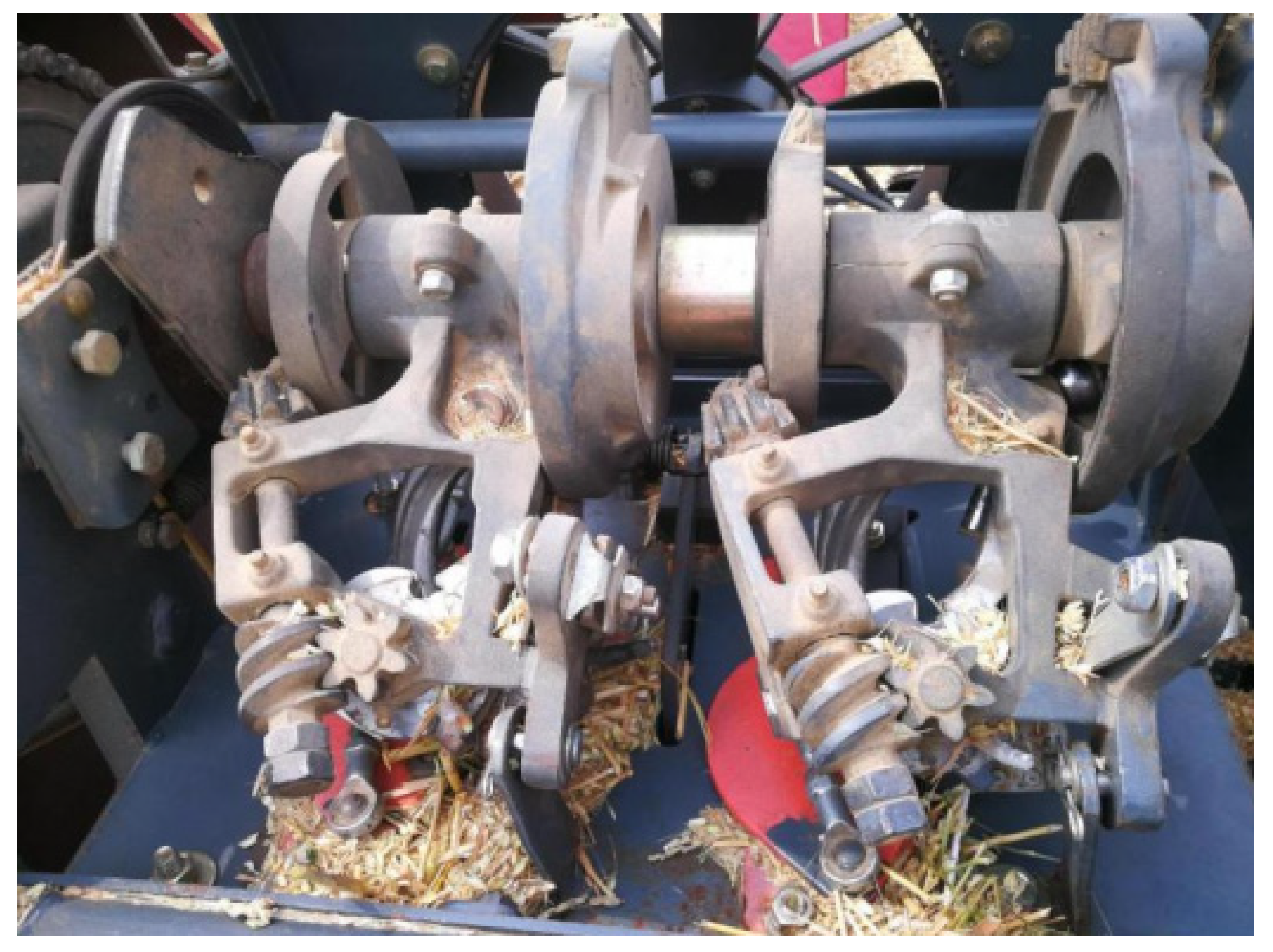
In order to conduct rapid wear tests, this batch of parts did not undergo surface strengthening treatment, resulting in significantly higher wear on the ground parts. Under the preset material and surface hardness conditions, the knotting number for the wear clearance of the tripping block to change from negative to zero was more than 5300 knots. At this time, the tripping block lost its forced tripping function, and the maximum wear depth of the cam on the large fluted disc was 0.89 mm. According to research [24], the relative wear resistance of the molybdenum steel material is inversely proportional to the average hardness of the worn surface, and materials such as the tripping block and large fluted disc belong to this category. Therefore, considering that the tripping block and ball roller are easily replaceable parts, the surface hardness difference between them and their grinding parts (knotter jaw and grooved cam) should be increased to 270 HBS or more. The recommended heat treatment process for the tripping block and large fluted disc is as follows: the casting parts should be annealed firstly, and then the overall quenching and tempering should be carried out to improve toughness, which is suitable for machining; at around 800 °C, surface quenching technology is used to achieve a surface hardness of around 300 HBS on the tripping block and around 570 HBS on the cam on the large fluted disc. Finally, tempering at a temperature of 150 °C to 200 °C is used to eliminate their internal stress. As shown in Figure 19, the knotter parts subjected to the above heat treatment were assembled on the baler for knotting tests. The knotter tied 60,000 knots and the ball roller and the tripping block were only replaced once. The wear depth of the grooved cam on the large fluted disc was within 1.5 mm, and the tripping action remained effective.

6. Conclusions

By using the combination of HyperMesh 2021 and ADAMS 2020 software, a rigid–flexible coupling dynamic model of the tripping mechanism can be established based on the modal stress method. The contact force curve and dynamic stress results of the contact pairs may be simulated, which can provide mechanical data for wear calculation of the tripping mechanism. Based on the MSC. Marc MENTAT finite element platform, a wear simulation model of the trip mechanism can be constructed to simulate the wear amount of the tripping block and the grooved cam. Through 6000 trip simulations, the key wear areas and expansion trends of worn parts were analyzed. The rapid wear tests showed that the maximum deviation between the measured and simulated values of the wear amount of the contact pair was less than 10%, which verifies that the proposed wear model for the tripping mechanism can be used for calculating the contact pair wear of other mechanisms and provides references for the heat treatment process of the surface hardness of the parts.

Author Contributions

Conceptualization, Y.G., and R.G.; methodology, J.Y.; writing—original draft preparation, Y.G.; writing—review and editing, Y.G., S.L., and M.Z.; project management, financial support, J.Y., D.Y., and M.Z. All authors have read and agreed to the published version of the manuscript.

Funding

This research was financially supported by the National Natural Science Foundation of China (Grant No. 51375215), and the Science and Technology Special Fund Project of Xinjiang Production and Construction Corps (No. 2024AB046).

Institutional Review Board Statement

Not applicable.

Data Availability Statement

The data presented in this study are available on request from the corresponding author. The data are not publicly available due to laboratory data privacy.

Acknowledgments

The authors thank the anonymous reviewers and journal editor for their valuable suggestions, which helped to improve the manuscript.

Conflicts of Interest

The authors declare no conflicts of interest.

References

  1. Zhou, D.; Li, M.; Li, Y.; Qi, J.; Liu, K.; Cong, X.; Tian, X. Detection of ground straw coverage under conservation tillage based on deep learning. Comput. Electron. Agric. 2020, 172, 105369. [Google Scholar] [CrossRef]
  2. Yin, J.; Chen, Z.; Lv, S.; Wu, H.; Gao, Y.; Wu, L. Design and fatigue life analysis of the rope-clamping drive mechanism in a knotter. Agriculture 2024, 14, 1254. [Google Scholar] [CrossRef]
  3. Zhao, Z.; Huang, H.; Yin, J.; Yang, S.X. Dynamic analysis and reliability design of round baler feeding device for rice straw harvest. Biosyst. Eng. 2018, 174, 10–19. [Google Scholar] [CrossRef]
  4. Tang, Z.; Li, Y.; Cheng, C. Development of multi-functional combine harvester with grain harvesting and straw baling. Span. J. Agric. Res. 2017, 15, e0202. [Google Scholar] [CrossRef]
  5. Li, H.; He, J.; Li, H.; Wang, Q.; Cao, Q.; Lu, W. Spatial parameters of knotters of square balers. Trans. Chin. Soc. Agric. Mach. 2013, 44, 99–105. [Google Scholar]
  6. Xiong, Y.; Li, H.; Chen, L.; Zhan, S.; Wei, W.; Han, L. Analysis and modification of interaction between wiper mechanism and billhook mechanism for knotter. Transactions of the Chinese Society for Agricultural Machinery. Trans. Chin. Soc. Agric. Mach. 2016, 47, 44–50. [Google Scholar]
  7. Li, H.; Xiong, Y.; Chen, J.; Zhang, S.; Li, X.; Han, L. Wear research and improved design of D-knotter wiper mechanism. Trans. Chin. Soc. Agric. Mach. 2015, 46, 118–124. [Google Scholar]
  8. Lv, S.; Chen, Y.; Yin, J.; Zhou, M.; Chen, Z. Anti-wear design of the knot-tripping mechanism and knot-tying test for the knotter. Lubricants 2023, 11, 475. [Google Scholar] [CrossRef]
  9. Chen, S.; Ding, H.; Tang, Z.; Hao, S.; Zhao, Y. Influence of rice straw forming factors on ring die wear and improved wear prediction model during briquetting. Biosyst. Eng. 2022, 214, 122–137. [Google Scholar] [CrossRef]
  10. Chen, S.; Zhao, Y.; Tang, Z.; Ding, H.; Su, Z.; Ding, Z. Structural model of straw briquetting machine with vertical ring die and optimization of briquetting performance. Agriculture 2022, 12, 736. [Google Scholar] [CrossRef]
  11. Bose, K.K.; Ramkumar, P. Finite element method based sliding wear prediction of steel-on-steel contacts using extrapolation techniques. Proc. Inst. Mech. Eng. Part J J. Eng. Tribol. 2019, 233, 1446–1463. [Google Scholar] [CrossRef]
  12. Wang, S.; Yang, X.; Li, X.; Chai, C.; Wang, G.; Wang, X. Simulation and experimental study on wear of u-shaped rings of power connection fittings under strong wind environment. Materials 2021, 14, 735. [Google Scholar] [CrossRef] [PubMed]
  13. Takeuchi, T.; Utsunomiya, T.; Gotoh, K.; Sato, I. Quantitative wear estimation for mooring chain of floating structures and its validation. J. Jpn. Soc. Nav. Arch. Ocean Eng. 2019, 30, 131–141. [Google Scholar] [CrossRef]
  14. Hou, Y.; Zhang, M.; Yuan, Q.; Li, Z.; Xu, R.; Kang, C.; Xiao, J. Research on the parameters design of inner lock for the aircraft landing gear retract actuator. Mach. Des. Manuf. Eng. 2016, 45, 74–79. [Google Scholar] [CrossRef]
  15. Zhang, M.; Jiang, R.; Nie, H. A numerical study on the friction and wear predictions of finger lock chuck in landing gear. Proc. Inst. Mech. Eng. Part G J. Aerosp. Eng. 2016, 231, 109–123. [Google Scholar] [CrossRef]
  16. Li, D.; Wang, Z.; Liang, Z.; Zhu, F.; Xu, T.; Cui, X.; Zhao, P. Analyzing rice grain collision behavior and monitoring mathematical model development for grain loss sensors. Agriculture 2022, 12, 839. [Google Scholar] [CrossRef]
  17. Wang, W.; Lv, X.; Yi, Z. Parameter optimization of reciprocating cutter for chinese little greens based on finite element simulation and experiment. Agriculture 2022, 12, 2131. [Google Scholar] [CrossRef]
  18. Huang, J.; Tan, L.; Tian, K.; Zhang, B.; Ji, A.; Liu, H.; Shen, C. Formation mechanism for the laying angle of hemp harvester based on ANSYS-ADAMS. Int. J. Agric. Biol. Eng. 2023, 16, 109–115. [Google Scholar] [CrossRef]
  19. Yin, J.; Gao, Q.; Chen, Y. Virtual knotting method of knotter based on rigid-flexible contact dynamics. Trans. Chin. Soc. Agric. Mach. 2016, 47, 85–92. [Google Scholar]
  20. Gao, Q. Research on Design Method of Knotter Based on Rigid-Flexible Contact Dynamics and Knotting Test. Master’s Thesis, Jiangsu University, Zhenjiang, China, 2016. [Google Scholar]
  21. Jiang, R.; Zhang, M.; Cai, J. Analysis on axial stiffness characteristics of a laminated rubber-metal spring. Mach. Des. Manuf. Eng. 2016, 45, 87–90. [Google Scholar] [CrossRef]
  22. Hu, Z.; Liang, K.; Wang, E.; Liu, X.; Jia, F. Numerical investigation on fretting wear in steel wires by introducing system stiffness and dissipated friction energy. Adv. Eng. Softw. 2025, 209, 103999. [Google Scholar] [CrossRef]
  23. Hutchings, I.; Shipway, P. Tribology: Friction and Wear of Engineering Materials, 2nd ed.; Elsevier Ltd.: Oxford, UK, 2017. [Google Scholar]
  24. Chintha, A.R. Metallurgical aspects of steels designed to resist abrasion, and impact-abrasion wear. Mater. Sci. Technol. 2019, 35, 1133–1148. [Google Scholar] [CrossRef]
Figure 1. Composition of tripping mechanism and wear compensation structure. 1. Ball roller; 2. knife arm; 3. tripping block; 4. knotter jaw; 5. rope-cutter; 6. adjustment shim; 7. rope-clearing knife; 8. secondary part on the tripping block; 9. primary part on the tripping block.
Agriculture 15 02229 g001
Figure 2. Knotter driven by double fluted discs with the same tooth trace. 1. Knotter bracket; 2. large fluted disc; 3. small fluted disc; 4. bevel gear fixed with worm shaft; 5. worm shaft; 6. right-handed worm; 7. spiral gear; 8. rope gripper; 9. bevel gear fixed with knotter jaw shaft; 10. knotter jaw; 11. split knife arm.
Agriculture 15 02229 g002
Figure 3. The rigid–flexible dynamic model of the tripping mechanism.
Agriculture 15 02229 g003
Figure 4. Multi-rigid cylindrical simulation of rope-tying.
Agriculture 15 02229 g004
Figure 5. Load time–history curves of contact parts of the tripping mechanism. (a) The contact between the tripping block and the knotter jaw; (b) the contact between the ball roller and the grooved cam on the large fluted disc; (c) the contact between the tripping block and the simulating rope.
Agriculture 15 02229 g005
Figure 6. (a) FFT of contact force between the ball roller and the grooved cam on the large fluted disc; (b) FFT of contact force between the tripping block and the knotter jaw.
Agriculture 15 02229 g006
Figure 7. (a) Deformation contour of the knife arm; (b) stress contour of the knife arm.
Agriculture 15 02229 g007
Figure 8. (a) Deformation contour of the large toothed disc; (b) stress contour of the large toothed disc.
Agriculture 15 02229 g008
Figure 9. Dynamic stress contour of the knife arm.
Agriculture 15 02229 g009
Figure 10. Dynamic stress contour of the large toothed disc.
Agriculture 15 02229 g010
Figure 11. Import the mesh for the MSC.MARC.
Agriculture 15 02229 g011
Figure 12. Wear cloud maps of tripping block at different stages. (a) 1000 trips; (b) 2000 trips; (c) 3000 trips; (d) 4000 trips; (e) 5000 trips; (f) 6000 trips.
Agriculture 15 02229 g012
Figure 13. Wear cloud map of grooved cam on large fluted disc at different stages. (a) 1000 trips; (b) 2000 trips; (c) 3000 trips; (d) 4000 trips; (e) 5000 trips; (f) 6000 trips.
Agriculture 15 02229 g013
Figure 14. Knotter wear test bench.
Agriculture 15 02229 g014
Figure 15. Surface state of worn ripping block.
Agriculture 15 02229 g015
Figure 16. Surface state of worn cam on the large fluted disc.
Agriculture 15 02229 g016
Figure 17. Wear measurement of tripping block. (a) 1000 trips; (b) 2000 trips; (c) 3000 trips; (d) 4000 trips; (e) 5000 trips; (f) 6000 trips.
Agriculture 15 02229 g017
Figure 18. Wear measurement of cam contour. (a) 1000 trips; (b) 2000 trips; (c) 3000 trips; (d) 4000 trips; (e) 5000 trips; (f) 6000 trips.
Agriculture 15 02229 g018
Figure 19. Knotter assembled on the baler.
Agriculture 15 02229 g019
Table 1. Material properties of the tripping mechanism parts.
ComponentMaterialElastic Modulus (Mpa)Poisson’s Ratio Density (kg/m3)
Knife arm, large fluted disc, knotter jawZG40CrMo210,0000.37850
Tripping block40Cr210,0000.37850
Ball roller304193,0000.297930
Table 2. Calculated maximum wear values after 6000 trips.
TripsTripping Block (mm)Grooved Cam (mm)
10000.21230.2496
20000.35940.5039
30000.53210.6802
40000.65340.7945
50000.73230.8650
60000.74710.9123
Disclaimer/Publisher’s Note: The statements, opinions and data contained in all publications are solely those of the individual author(s) and contributor(s) and not of MDPI and/or the editor(s). MDPI and/or the editor(s) disclaim responsibility for any injury to people or property resulting from any ideas, methods, instructions or products referred to in the content.