Abstract
To address the challenge of improving the accuracy and efficiency of automatic transplanting operations in pepper plug seedling transplanters, this study innovatively designed a follow-up seedling picking and depositing mechanism. The core innovation lies in the synchronization of the seedling picking claws with the moving seedling cups, which was achieved by coordinating the motion speeds of the seedling picking and depositing mechanism with the seedling conveying mechanism. This synchronization ensured relative spatial stillness during seedling deposition, significantly enhancing seedling depositing accuracy. To meet the design requirements of this follow-up mechanism, this study presents a comprehensive design of the transplanter, including a three-dimensional model. Key mechanisms, namely the seedling picking and depositing mechanism and the seedling conveying mechanism, were thoroughly analyzed, with detailed explanations of their working principles. The transmission system was designed for reliability and stability, being towed by a tractor with the ground wheel driving the motion of the seedling conveying and distributing mechanisms. The motion mode of the seedling picking and depositing mechanism combined a crank–rocker mechanism and a crank–slider mechanism, utilizing a gear transmission rod for seedling picking and carrying actions, and rail guidance for follow-up seedling depositing. Experimental results validated the effectiveness of this design. In bench tests, the success rates of the seedling picking and depositing mechanism at operating speeds of 100 seedlings/min, 150 seedlings/min, and 200 seedlings/min were 97.4%, 98.44%, and 95.03%, respectively. In field tests, at operating speeds of 90 seedlings/min, 120 seedlings/min, and 150 seedlings/min, the planting success rates were 99.65%, 94.95%, and 89.18%, respectively. These results demonstrated that the follow-up seedling picking and depositing mechanism met the demands of automatic transplanting operations, offering an effective solution to enhance both the operating speed and quality of the transplanter.
1. Introduction
Plug seedling transplanting technology, as a key technology for large-scale modern vegetable production, has been widely applied due to its outstanding advantages in enhancing crop yield and quality [1,2,3]. Compared with traditional direct-seeding cultivation methods, this technology can effectively shorten the crop growth cycle, increase the multiple cropping index, and cultivate standardized plug seedlings with well-developed root systems and uniform growth, providing an important foundation for mechanized operations [4,5,6]. Based on these technological characteristics, significant progress has been made in the research and development and application of transplanters [7,8]. Mechanized transplanting not only significantly improves the quality and efficiency of operations but also reduces labor intensity and production costs, promoting the development of vegetable production toward high efficiency and standardization [9,10,11].
China has conducted years of research in the field of transplanters, and currently, there are numerous types and models available. Wang Yongwei et al. [12] designed an automatic transplanter for dryland vegetable plug seedlings using key components such as an elliptical incomplete non-circular gear planetary gear train rotary seedling picking mechanism, a horizontal–vertical seedling feeding mechanism, and an eccentric hanging cup planter. This transplanter achieved automated operations for seedling feeding, picking, planting, and soil covering, with an optimal planting frequency of 45–96 seedlings/(minute·row). Yan Hua et al. [13] developed the 2ZBJ-4 automatic transplanter using mechatronic integration technology. In this transplanter, the seedling picking and depositing processes are controlled by a combination of a control system and sensors to operate mechatronic components. Each seedling picking mechanism contains multiple seedling-picking claws and adopts a rotary seedling feeding method, resulting in a high seedling picking success rate and a transplanting efficiency of up to 5400 seedlings/(h·row). Han Changjie et al. [14] installed an automatic seedling picking and feeding system on a hanging basket semi-automatic transplanter and developed an automatic transplanter for pepper plug seedlings. Tests showed that this transplanter achieved a planting success rate of 96.97%, meeting the requirements for hole-forming transplanting on plastic film. However, it requires pre-laying of plastic film and drip irrigation tapes, resulting in multiple operational procedures. European and American countries have advantages in terms of the automation level and operational efficiency of transplanters. The Mark5 five-row fully automatic vegetable transplanter produced by Pearson in the UK [15] can achieve a transplanting efficiency of up to 12,600 seedlings/row/h. The Futura series automatic transplanter designed by Ferrari in Italy [16] picks seedlings using a top-clamping combination method and has a transplanting efficiency as high as 8000 seedlings/(row·h), but it requires the use of specialized rigid plug trays. The RTME1100 transplanter from Renaldo in the USA [17] integrates a seedling collecting and transplanting system, a hydraulic control system, a watering system, and a plastic film treatment system and features an automatic chassis lifting function, resulting in excellent planting effects on plastic film. During operation, seedlings are manually placed into seedling cups, classifying it as a semi-automatic transplanting device. The seedling picking and depositing mechanism of a pepper transplanter is a core component that directly affects transplanting efficiency and planting quality. Currently, research on seedling picking and depositing mechanisms at home and abroad mainly focuses on mechanical structure optimization, motion trajectory control, and adaptability improvement. Yu Gaohong’s team [18] designed a rotary seedling picking device that uses gear transmission to drive seedling picking claws along a predetermined trajectory, enabling single-seedling picking and depositing at a speed of 60–80 seedlings/min. The planetary gear train seedling picking and depositing mechanism developed by Yanmar [19] performs excellently in high-speed transplanting operations, enabling stable single-seedling reciprocating picking and depositing with an operational frequency of up to 90–110 seedlings/min. In summary, the operational speed of whole-row seedling picking and depositing is superior to that of single-seedling picking methods.
In general, the current operational speed of transplanters is low, and the difficulty in improving the operational speed of seedling picking and depositing mechanisms is a key factor restricting the enhancement of the overall operational speed of transplanters. Although the operational speeds of seedling picking and depositing mechanisms in current transplanters can reach relatively high levels, most of them are still at the research and development phase and often rely on linear modules and cylinder drives to achieve seedling picking and depositing functions, making reliability difficult to ensure during field operations [20]. At the same time, for existing whole-row seedling picking and depositing transplanters, the seedling picking and depositing mechanism must cooperate with the seedling conveying mechanism to achieve ordered planting. During seedling depositing, the existing whole-row seedling picking and depositing mechanisms are stationary, but the seedling conveying mechanism must continuously move during operation. Therefore, even if the existing seedling picking and depositing mechanisms have high seedling picking and depositing speeds, inaccurate seedling depositing is a key factor restricting their development [21,22].
Therefore, breaking through the technical dilemma of balancing high speed and high accuracy in transplanting operations fundamentally hinges on resolving the relative motion issue between the seedling picking mechanism and the conveying mechanism at the moment of seedling depositing. Based on this, our study innovatively designs a mechanically driven follow-up seedling picking and depositing mechanism. Its core innovation lies in the fact that during the seedling depositing process, the seedling picking claws can synchronize with the moving seedling cups, achieving “spatially stationary seedling depositing,” which theoretically eliminates depositing errors caused by relative motion. This paper aims to elaborate in detail on the design, optimization, and validation process of this mechanism, and to compare it with existing technologies, thereby demonstrating its effectiveness and engineering application value in enhancing the comprehensive performance of high-speed transplanting operations.
2. Materials and Methods
2.1. Agronomic Requirements for Pepper Cultivation
In Xinjiang, Natural pigment pepper cultivation was predominantly in sandy soil areas with abundant sunlight and excellent drainage. Such soil conditions were conducive to the healthy development of pepper root systems and effectively helped prevent and control pests and diseases. During the cultivation process, the seedling transplanting technique was employed, where pepper seedlings were raised in greenhouses or seedling beds and then transplanted to the field once they reached the appropriate seedling age. This method allowed for precise control over the growth environment of the seedlings, thereby significantly improving their survival rate after transplanting. Based on the growth characteristics of peppers and the demands of field management, the planting density was designed following the principle of optimal configuration. Reasonable row spacing and plant spacing not only ensured that each individual plant receives sufficient sunlight and nutrient supply but also provided the necessary space and convenience for mechanized operations. In the early growth stages of peppers, plastic film mulching technology was utilized to enhance soil temperature and promote rapid seedling development. A typical set of agronomic structural parameters for pepper cultivation is illustrated in Figure 1 and detailed in Table 1. In Xinjiang, field pepper cultivation typically selects sandy soil regions with ample sunlight and good drainage. Such soil not only supports the healthy development of pepper root systems but also effectively reduces the incidence of pests and diseases [23]. The primary cultivation method employed was seedling transplanting, which allowed for better control over the growth environment of peppers and improved survival rates. Seedlings were usually raised in greenhouses or seedling beds and then transplanted to the field once they reached a certain size.
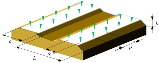
Figure 1.
Schematic diagram of agronomic parameters for film-mulched pepper transplanting in field.

Table 1.
Range of agronomic parameters for film-mulched pepper transplanting in field.
The dimensional parameters of key components of an automatic transplanter, including row spacing, film width, and ridge height, need to be reasonably designed according to the actual requirements of pepper cultivation. Meanwhile, the transmission ratios of various components should be inversely designed based on the plant spacing requirements to ensure that the transplanter can meet the needs of local pepper transplanting production.
2.2. Morphological Characteristics of Plug Seedlings and Plug Trays
In Xinjiang, pepper plug seedlings are predominantly cultivated in standardized seedling nurseries, with a seedling age ranging from 45 to 60 days. To facilitate centralized and large-scale seedling production, 128-cell plug trays (8 rows × 16 columns) are commonly used. The plug trays shown in Figure 2a. The designed dimensions of the substrate square cells are 31 mm in length (Lc) and 45 mm in depth (Hp). The plug tray measures 535 mm in length and 280 mm in width. The substrate for the plug seedlings is a mixture of peat, vermiculite, and perlite in a 1:1:1 volume ratio. Prior to transplanting, the stem of pepper plug seedling is erect and exhibits minimal variation in overall dimensions, as depicted in Figure 2b. The external dimension parameters of the plug seedlings that are closely related to the structural parameters of the key components of the automatic transplanter include the maximum leaf spread (c), ranging from 90 to 150 mm; hₘ, representing the maximum height of the stem and leaf portion of the plug seedling; hₗ, indicating the height of the lowest leaf from the top surface of the substrate; and the overall height range of the plug seedlings being 140 to 200 mm. These data provide a reference for the design of seedling cup dimensions and support the determination of the gripper position. Additionally, the width of the substrate’s top surface m = 31 mm (±3 mm) and the height h = 45 mm (±5 mm) of the substrate determine the design gripping angle and range of a single gripper.
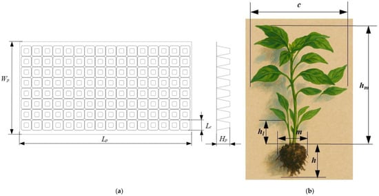
Figure 2.
Morphological characteristics of plug seedlings and plug trays: (a) plug tray dimensions; (b) plug seedling dimensions.
2.3. Overall Machine Structure and Working Principle
Based on the agronomic requirements for field pepper cultivation, the growth dimensions of plug seedlings, and the geometric parameters of standard plug trays, a traction-type automated transplanter has been designed. This machine is capable of automatically performing tasks such as seedling feeding, picking and depositing seedlings, seedling separation, seedling transportation, planting, and soil covering. The frame serves as the supporting structure for the entire machine, ensuring the stable installation and coordinated operation of all components. The ground wheel mechanism, which directly contacts the ground, not only drives the machine forward but also powers various functional mechanisms through chain and gear transmissions. The seedling tray feeding mechanism, driven by a cylinder and actuated by a ratchet, advances the plug tray one cell at a time, providing an orderly supply of seedlings row by row. The seedling picking and depositing mechanism accurately extracts plug seedlings using a specially designed gripper structure and places them into the transplanting cups. The seedling conveying mechanism sequentially receives plug seedlings released by the gripping claw, transports them to the position above the planter, and release the seedlings into the planting unit in a controlled manner. The planting and soil covering mechanisms employ duckbill-type planting and soil covering devices to ensure efficient and reliable soil covering after planting the plug seedlings. The downward penetration force is provided by the machine’s weight. A compression spring connecting the planter to the frame serves as a passive adaptive mechanism, dynamically adjusting the force applied to the soil based on its resistance (e.g., firm or soft ground), thereby ensuring consistent planting depth and preventing mechanical overload. The structure of the transplanter is illustrated in Figure 3, and the machine is suitable for two-row transplanting (This figure and all the 3D figures in this paper were drawn using Solidworks2025 (version 2025 SP1, Dassault Systèmes, Waltham, MA, USA). The row spacing and plant spacing are adjustable, providing high adaptability to meet various transplanting requirements. Row spacing is adjusted by modifying the lateral position of the planter relative to the machine frame, while plant spacing is regulated by replacing sprockets with varying tooth counts in the ground wheel drive system. This modification alters the speed ratio between components, enabling precise plant spacing control through gear ratio adjustment. The transplanter working parameters are shown in Table 2.
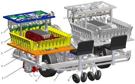
Figure 3.
Structural diagram of the automatic transplanter: 1. seedling picking and depositing mechanism, 2. seedling conveying mechanism, 3. pneumatic seedling tray feeding mechanism, 4. machine frame, 5. rotary tillage mechanism, 6. ground wheel mechanism, 7. duckbill-type planting mechanism, 8. soil covering wheel.

Table 2.
Main parameters of device.
2.4. Working Principle of the Key Mechanisms
To enhance planting accuracy, the precision of transmission ratios in critical components was ensured. A gear-chain transmission system was adopted to achieve precise motion transfer between components. Given the spatiotemporal complexity of seedling pickup trajectories and the spatial heterogeneity of plug seedlings, linear guide rail guidance mechanisms, curved groove constraint devices, ratchet mechanism, and four-bar linkage mechanisms were innovatively integrated. Through series-connected transmission chain topologies and parallel kinematic decoupling, a composite motion control model was constructed, ultimately achieving sub-millimeter synchronization of functional modules, as shown in Figure 4.
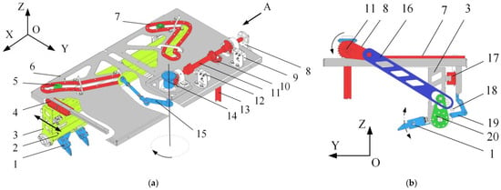
Figure 4.
Schematic of the composition and workflow of the automatic seedling picking and depositing system: (a) partial sectional view of the automatic seedling picking and depositing mechanism; (b) view from direction a of the automatic seedling picking and depositing mechanism. 1. Seedling claw assembly, 2. transverse slide rail for seedling claw assembly, 3. suspension frame of seedling claw assembly, 4. longitudinal slide rail, 5. rollers connected to the upper end of the seedling claw assembly, 6. top plate, 7. slide track, 8. side crank, 9. control valve for the seedling claw assembly’s clamping cylinder, 10. bevel gear transmission I, 11. horizontal transmission shaft, 12. control valve for the seedling tray feeding cylinder, 13. vertical trans-mission shaft, 14. bevel gear transmission ii, 15. slider–crank mechanism, 16. side connecting rod, 17. seedling claw-driven transverse slide rail, 18. tension spring, 19. swing arm of seed-ling claw assembly, 20. seedling picking swing rod.
The automatic seedling picking and depositing mechanism is a core component of the transplanter, with its operational performance directly affecting the speed and quality of transplanting operations, as shown in component No. 1 of Figure 3. The power for the automatic seedling picking and depositing mechanism is entirely sourced from the ground wheel, which transmits motion through a drive chain and a gearbox.
The input power is transferred through bevel gears to drive a horizontal transmission shaft, generating torque T. The power is then distributed in parallel to both ends of the horizontal transmission shaft. On the outer side of the horizontal transmission shaft, it drives a crank and a connecting rod, which in turn cause the seedling picking swing rod to oscillate at a predetermined angular position. On the inner side, it drives a slider–crank mechanism via bevel gears. Under the coupled motion of these two mechanisms, the seedling claw assembly achieves precise movement along a spatial trajectory.
To enhance the stability of seedling picking and depositing, a tension spring is attached to the swing arm of the seedling claw assembly at the other end, reducing vibrations during the movement of the seedling claw assembly. On the opposite side of the horizontal transmission shaft, it drives bevel gears, which then actuate the slider–crank mechanism to move the seedling claw assembly suspension back and forth along the longitudinal slide rail. This ensures that the bottom seedling claw assembly accurately reaches the positions for seedling picking and depositing.
The upper end of the seedling claw assembly moves along the slide track via connecting rollers and achieves equidistant expansion of the seedling claw assembly on the transverse slide rail. This ensures the precise placement of plug seedlings into the seedling cups.
The seedling tray feeding cylinder control valve and the seedling claw gripping cylinder control valve are used to control their respective actuating cylinders. Both sets of control valves are mounted on one side of the bevel gear transmission shaft and remain in contact with two cams on the shaft. Mechanical triggering of the actuating cylinders’ extension and retraction is achieved through variations in the cam profiles. The timing sequences of the pneumatic tray feeding and seedling picking/depositing operations are precisely synchronized with the rotational phase of the transmission shaft, ensuring coordinated movement between the closing/opening of the seedling claws and the seedling feeding action of the tray mechanism. This enables precise control over the operational cycle.
2.4.1. Working Principle of the Seedling Separating Mechanism
During automatic seedling picking, the central positions of the eight seedling claws must strictly align with the centers of each column of plug seedlings in the tray, i.e., the minimum center distance Zmin equals the plug seedling center spacing of 31 mm in the tray. At this point, the spread distance between the outermost pairs of seedling claws is Bmin = 31 × 7 = 217 mm.
When the seedling claws move toward the depositing position, grippers 1 and 5 slide outward along guide rails and uniformly expand under the action of limiting hinges, increasing the center distance to the designed seedling cup center spacing Zmax of 95 mm. The spread distance between the outermost pairs of grippers at this stage is Bmax = 95 × 7 = 665 mm, perfectly matching the seedling cup center spacing.
In the slot structure, the distance from the center of the circular hole to the near end of the elongated slot equals the adjacent plug seedling center spacing Zmin in the tray, while the distance to the far end equals the adjacent seedling cup center spacing Zmax. The dimensions of the elongated slot satisfy the displacement requirements of the separating mechanism in the X-direction, ensuring smooth transition of the grippers from the plug seedling center spacing to the seedling cup center spacing before and after expansion. Structural diagrams of the separating mechanism before and after expansion are shown in Figure 5.
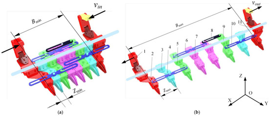
Figure 5.
Schematic diagram of the seedling separating mechanism: (a) seedling picking state of seedling separating mechanism; (b) seedling depositing state of seedling separating mechanism. 1. Swing arm of seedling claw assembly, 2. gripper 1, 3. gripper 2, 4. slotted guide 1, 5. gripper 3, 6. slotted guide 2, 7. gripper 4, 8. slotted guide 3, 9. slide rail, 10. slotted guide 4, 11. gripper 5, Bmin: minimum center distance between adjacent plug seedling substrates, Bmax: maximum center distance between adjacent seedling cups.
2.4.2. Working Principle of the Seedling Conveying Mechanism
After seedling separation, the conveying mechanism precisely aligns the expanded centers (Zmax) of the eight seedling claws with the centers of eight seedling cups. By using components such as the driving sprocket, seedling cup conveyor chain, support plate, and seedling cup opening ramp mechanism, it achieves continuous transportation and depositing of plug seedlings.
As shown in Figure 6, the conveyor chain rotates counterclockwise, carrying the attached seedling cups along a trajectory toward the seedling release position. When the force-receiving roller on the side of a seedling cup contacts the opening ramp mechanism, the roller is pressed downward, opening the cup base. The plug seedling then falls precisely into the planting mechanism below under gravity.
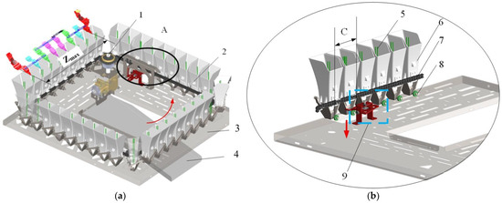
Figure 6.
Schematic diagram of the seedling conveying mechanism: (a) 3D view of the seedling conveying mechanism; (b) partial enlarged view (section a) of the seedling conveying mechanism. 1. Driving sprocket, 2. seedling cup conveyor assembly, 3. support plate, 4. seedling tray guide outlet, 5. plug seedling, 6. seedling cup, 7. seedling cup conveyor chain, 8. force-receiving roller, 9. seedling cup opening ramp mechanism. Where C denotes the center distance between seedling cups, and area A is a partial enlarged view.
To ensure synchronization between conveying and picking/depositing actions, the conveyor maintains a strict gear ratio with the picking/depositing mechanism: Every time the conveyor chain advances the distance equivalent to eight cup positions, the picking/depositing mechanism executes one cycle. This ensures a continuous supply of seedlings, prevents empty cups, and achieves fully automated integration of separation, conveying, and depositing.
2.4.3. Working Principle of the Automatic Tray Feeding Mechanism
The automatic tray feeding mechanism has operated based on pneumatic control and cam phase coordination to ensure precise alignment with the picking/depositing mechanism (see Figure 7). It combines a cylinder with a ratchet mechanism, and the intermittent motion of the ratchet mechanism enables the plug seedling tray to be fed, thereby fulfilling the timing requirements for automatic seedling picking and depositing operations.
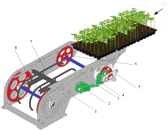
Figure 7.
The automatic tray feeding mechanism: 1. support frame, 2. executive cylinder, 3. connecting rod, 4. ratchet wheel, 5. limiting pawl, 6. driving sprocket, 7. plug tray support frame, 8. driven sprocket.
When the transmission shaft and ground wheel operate in tandem according to a predefined gear ratio, the cam mechanism controls the opening and closing of the pneumatic cylinder valve, thereby actuating the reciprocating motion of the executive cylinder. This linear motion is transferred via a connecting rod to drive the rotation of a ratchet wheel. With each tooth engagement of the ratchet, the driving sprocket advances by one position, inducing a displacement of the chain on the automatic tray feeder that matches the center-to-center spacing (pitch) between adjacent plug seedling columns. This ensures that after each column of seedlings is released, the tray moves precisely to the next picking station, guaranteeing exact alignment for subsequent seedling retrieval.
2.4.4. Working Principle of the Seedling Cup
A bilateral symmetrical gate mechanism was implemented at the base of the seedling cup. During closure, this mechanism supported and transported plug seedlings, while simultaneous opening of both gates enabled gravitational self-release of the seedlings. Roller-actuated synchronized linkage transmission systems ensured rapid and reliable actuation of the opening/closing processes, as illustrated in Figure 8.
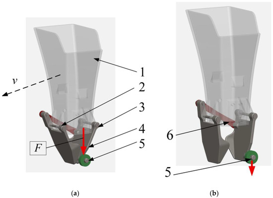
Figure 8.
Structural and operational schematic of the seedling cup: (a) closed state; (b) open state. 1. Cup body, 2. torsion spring, 3. connecting pin, 4. bottom panel, 5. roller, 6. linkage plate, F: downward actuation force.
When a substrate-filled plug seedling reaches the depositing position with the automated seedling picking mechanism, the substrate maintains a consistent orientation while falling into the seedling cup. As the conveyor chain continues to move, the roller on the outer side of the bottom Panel contacts a fixed inclined plane or trigger pin, generating a downward force F and causing the panel to pivot around the hinge pin. This motion synchronously pulls the opposite door panel via a connecting rod, enabling both panels to open rapidly and expand in parallel within ≤0.1 s. The plug seedling is then precisely released into the underlying planter under the action of gravity. After the trigger force is removed, the high-strength spring restores the door panels to their closed position, ensuring readiness for the next cycle.
2.5. Key Mechanism Design of the Transplanter
2.5.1. Trajectory Planning for Automated Seedling Picking and Depositing
The trajectory design for automated seedling picking and depositing must be determined based on the positions of the seedling tray and the seedling cup in the seedling transport mechanism [24]. Assuming the picking and depositing planes are located within the YOZ plane and to minimize the external dimensions of the automated mechanism, it is assumed that there is no height difference (ΔZ = 0) between the picking and depositing positions along the Z-axis. Thus, the Z-direction motion only considers complete extraction of the substrate from the seedling tray. In the Y-direction, the distance between the center of the seedling cup and the origin O of the picking position on the seedling tray must be determined.
As illustrated in Figure 9, the plug seedlings, seedling cup conveyor chain, and seedling tray move independently without interference. Based on the actual dimensions of each component, the picking and depositing distance in the Y-direction consists of at least three segments: l1—Distance between the center of the seedling cup and the outer edge of the seedling cup conveyor chain. l2—Clearance between the outer edge of the seedling cup conveyor chain and the outer edge of the seedling tray. l3—Horizontal distance between the outer edge of the seedling tray and the picking position. l1 = (seedling cup side length)/2 + 20 mm = 100/2 + 20 = 70 mm; l2 = clearance allowance = 30 mm; l3 = radius of the automatic tray feeding mechanism sprocket (r) = 130 mm. Thus, the total distance in the Y-direction is 230 mm. This design ensures interference-free operation while maintaining required precision and spatial constraints.
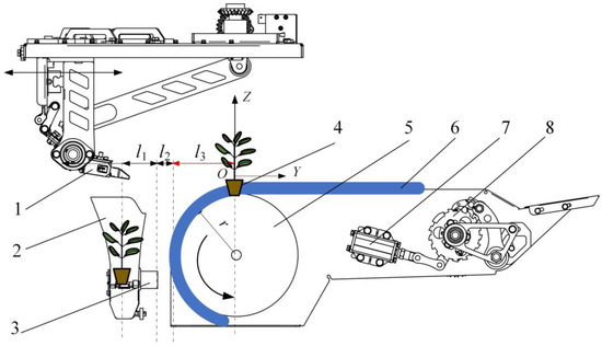
Figure 9.
Schematic diagram of component positions for automated seedling picking and depositing mechanism: 1. seedling clamp, 2. seedling cup, 3. seedling cup conveyor chain, 4. plug seedling, 5. automatic tray feeding mechanism sprocket, 6. seedling tray, 7. executive cylinder of the automatic tray feeding mechanism, 8. ratchet mechanism. Note: r = sprocket radius; l1 = distance between seedling cup center and conveyor chain outer edge; l2 = clearance between conveyor chain and tray outer edges; l3 = horizontal distance between tray outer edge and picking position.
2.5.2. YOZ Plane Trajectory Planning for Automated Seedling Picking and Depositing Mechanism
To achieve a three-dimensional (3D) picking and depositing trajectory using only common planar linkages, this study first designs matching motion curves in the XOZ and YOZ projection planes, then synchronizes them through precise gear ratio calculations to obtain the desired spatial trajectory (Figure 10).
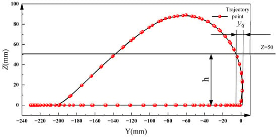
Figure 10.
Trajectory of the seedling clamping point in the YOZ plane.
Taking the YOZ plane as an example, a Y (longitudinal)-Z (height) coordinate system is established, with the picking point at (0, 0) and the depositing point at (−230 mm, 0). After the gripper clamps the stem of the plug seedling, the picking trajectory requires a rapid vertical ascent to h = substrate depth (45 mm) + substrate tray height (5 mm) = 50 mm, ensuring complete detachment of the seedling from the tray cell wall without compression forces. To accommodate loose deformation at the substrate base, an additional 30 mm safety margin is provided, resulting in a total elevation of 80 mm. During this process, the Y-axis coordinate fluctuation (yq) must be minimized to ensure smooth lateral motion. After reaching the 80 mm apex, the gripper descends gradually along a reverse curve to the position (Y = −230 mm, Z = 0), achieving smooth docking with the seedling cup and completing the depositing action.
2.5.3. Design of the XOY Plane Crank–Slider Mechanism for Seedling Transplantation
After the seedling-picking claw completes the automatic clamping action, trajectory planning is required to enable the seedling-picking claw assembly to reach the seedling depositing position within the horizontal plane. The crank–slider mechanism was implemented to transform rotational input into linear output, achieve reciprocating linear displacement between the seedling-picking position and the seedling-depositing position. Assuming that the horizontal plane coordinate system is defined as XOY, the straight-line distance between the seedling-picking position and the seedling-depositing position is the distance between points B2 and B3 in Figure 11 (230 mm).
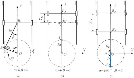
Figure 11.
Schematic diagram of the motion states of the crank–rocker mechanism for seedling separation: (a) seedling-carrying motion state; (b) depositing-position state; (c) picking-position state. Note: O is the rotation center of the crank; A1A2A3O represents the positions of the crank end at different moments; B1B2B3 represents the positions of the slider at different moments; α is the included angle between the crank and the line OB (°); β is the included angle between the connecting rod AB and the line OB (°); θ is the included angle between the connecting rod and the Y-axis direction (°); ω is the rotational speed of the crank (rad/s); R1 is the length of the crank (mm); R2 is the length of the connecting rod (mm).
Considering the requirements for lightweight design and force balance during the picking process, this design adopts a non-eccentric crank–slider structure. Under the power transmission of bevel gears, the crank OA1 rotates clockwise at an angular velocity ω, with a crank length of R1; the connecting rod A1B1 has a length of R2. In the initial state, the included angle between the crank OA1 and the line OB1 passing through the hinge center O and the slider center B1 is α, the included angle between the connecting rod A1B1 and OB1 is β, and the slider is located at point B1. When the crank rotates through an angle α, the crank coincides with the connecting rod, and the slider moves a linear distance Y12 to reach B2 (the seedling-depositing position); when the crank continues to rotate to 180°, the crank coincides with the connecting rod again, and the slider moves a distance Y23 to reach B3 (the seedling-picking position).
Based on the positional relationship between the automatic tray-feeding mechanism and the seedling-conveying mechanism, as well as the required design clearance, the minimum value of the slider stroke Y23 is set to 230 mm. When the crank rotates to α1 = 90°, the slider is exactly at the mid-point of its stroke, and at this time, Y12 = Y23/2 = 115 mm. Under the assumption that the crankshaft and the slider guide rail are coaxial and the offset is zero, its kinematic parameter equations can be expressed as follows:
Based on the stroke relation, y(0) − y(180°) = 2R1 = 230, R1 is determined to be 115 mm. From the precise point,
Therefore, R2 = R1 = 162.63, and the rounded-off dimension is 170 mm.
2.5.4. Design of the Seedling-Separation Trajectory for the Seedling-Separation Mechanism in the XOY Plane
Driven by the crank–slider seedling-transplantation mechanism, the seedling-picking claws move from the seedling-picking area B (in the Y direction) to the seedling-depositing area B1. To ensure accurate seedling separation, for each row of 8 seedlings, the initial spacing Zmin in the X direction needs to be expanded to Zmax: The starting positions of the outermost claws are denoted as C0 and D0, and their positions after expansion are denoted as C1 and D1. To improve the success rate of seedling depositing, the seedling-picking claws continue to move synchronously to C2 and D2, with synchronous distances of C1C2 and D1D2 respectively (as shown in Figure 12). Based on the trajectory point sequences C0 → C1 → C2 and D0 → D1 → D2 in the XOY plane, combined with the crank–slider mechanism described in Section 2.5.2, a roller-slot mechanism is used to achieve complex positional motion. When the slider slides a distance of Y23 to reach B1, the center-to-center distance of the outermost claws is exactly Zmax, which is aligned with the center of the seedling cups, meeting the requirements for seedling depositing. In addition, the authors of [25] indicates that the angles θ1–θ4 between the roller trajectories and the X-axis should all be greater than 45° to optimize transmission efficiency and enhance structural safety.
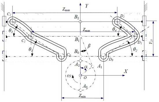
Figure 12.
Schematic diagram of the seedling-separation mechanism in the XOY plane. Note: Y23 is the distance in the Y direction from the seedling-picking point to the seedling-depositing point. A0, A1, and A2 are the three positions of the crank end-point, respectively. B0, B1, and B2 are the three positions of one end-point of the connecting rod, respectively. C0, C1, and C2 are the three trajectory points of the center of the left-side roller within the slot. D0, D1, and D2 are the three trajectory points of the center of the right-side roller within the slot. θ1 and θ3 are the angles between the lines C0C1 and C1C2 of the left-side roller and the X-axis, respectively. θ2 and θ4 are the angles between the lines D0D1 and D1D2 of the right-side roller and the X-axis, respectively. Zmin is the total center-to-center distance of the seedling claws during seedling picking, and Zmax is the total center-to-center distance of the seedling claws during seedling depositing. α is the angle between the crank OA1 and the Y-axis, β is the angle between A1B1 and the Y-axis, and ω is the rotational speed of the crank.
2.5.5. Design of the Crank–Rocker Seedling-Picking Mechanism
To accomplish the picking or depositing of plug seedlings, a certain angular swing is required after the seedling claws reach the target position. This process can be realized by using a crank–rocker mechanism to achieve the angular swing of the seedling claws. The mechanism principle of this design is shown in Figure 13, where the coordinate plane is the YOZ plane. The length of the crank OA is r, which rotates uniformly at an angular velocity ω. The length of the connecting rod AB is l. The initial angle of the rocker BC is α0, the length of CM is a, and CM forms a fixed angle with the rocker BC. When the rocker BC swings angularly, the end-point M also forms a swinging trajectory, and φ is the angle between CM and the Y-axis. The motion of point M is influenced by multiple parameters, including the lengths of the connecting rods a and d, the angle of the rocker φ and its derivative, and the angular velocity ω. In particular, adjusting these parameters can significantly change the shape, direction, periodicity, and nonlinear characteristics of the trajectory of point M.
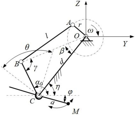
Figure 13.
The crank–rocker mechanism. Note: ω is the angular velocity of the crank, r is the crank radius, l is the length of the connecting rod, d is the length of the fixed hinge OC, a is the length of CM, M is the gripping point of the seedling claws, θ is the extreme-position angle of the rocker, and φ is the angle between CM and the horizontal plane.
The projection of point M in the Z direction is H, where H = 80 mm. To meet this requirement, if the length of the crank OA takes the minimum value, according to common aperture standards (the common aperture of the crank is 20 mm, and the common machining aperture of the connecting rod is 30 mm), for the intermediate connecting material part, the crank length is set to 90 mm, and the length of CM, a = 130 mm. Let the angle between CM and the y-axis (height direction) be θ (i.e., the rotation angle of CM, where it is specified that when CM is in the positive y-axis direction, θ = 15° to facilitate the non-friction between the bottom surface of the seedling claws and the surface of the plug tray).
Substituting H = 80 mm and a = 130 mm into Formula (3), we get cosθ ≈ 0.6154. Then, θ is solved using the inverse cosine function: θ = arccos(0.6154) ≈ 52.02°. Since the initial rotation angle of CM is 15° downward from the horizontal direction, the angle after upward swinging is 52–15° = 37°. That is, when swinging within this angular range, the height projection of the seedling-picking point M meets the seedling-picking conditions, ensuring that the seedling claws can complete the seedling-picking operation smoothly.
2.5.6. Coupled Design of Multi-Planar Mechanisms
The crank–rocker mechanism can convert external rotational torque into angular oscillation of the seedling-picking claw. However, if the hinge point of its rocker is fixed, it cannot enable the seedling-picking claw to achieve repetitive linear motion in the Y-direction. To solve this problem, by combining it with the crank–slider seedling-separation mechanism, a long-distance reciprocating linear motion of the seedling claws in the Y direction can be achieved to reach the seedling-picking and depositing positions. At the same time, the angular swing of the seedling claws is required to be an intermittent motion, that is, the rocker starts to swing when the seedling claws grip the seedlings, prompting the plug seedlings to leave the plug tray; then, it swings back to the seedling-depositing point and stops swinging until the seedling depositing is completed and it reaches the seedling-picking position again. To achieve this goal, the slot mechanism is coupled with the crank–rocker mechanism and the crank–slider seedling-separation mechanism to form a unified power transmission, thereby generating the expected composite motion trajectory. The coupled mechanism is shown in Figure 14.
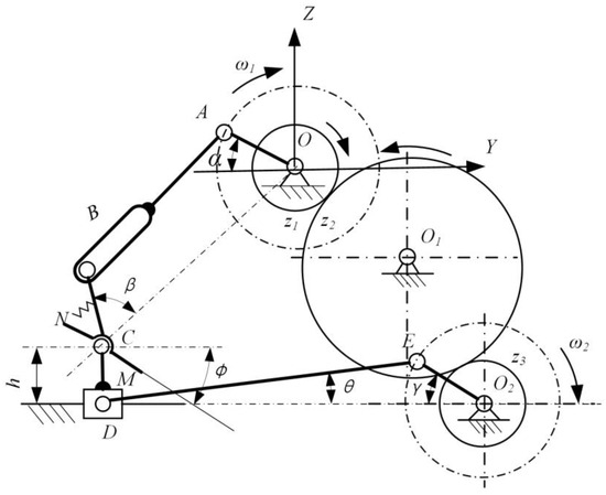
Figure 14.
Schematic diagram of the coupled principle of the multi-planar mechanism for automatic seedling picking and depositing.
The rotational torque of the crank OA comes from the ground wheel. The frictional force between the ground wheel and the ground provides the power source and transmits it to other moving parts, such as the crank OA and O2E, to form synchronous motion. The crank OA and O2E are coaxial, and their angular velocities are equal (i.e., ω1 = ω2). The crank OA, the connecting rod AB, and the rocker BC together form a crank–rocker mechanism, and point B moves within the slot. The crank O2E, the connecting rod ED, and the slider D together form a crank–slider mechanism. The slider D is fixedly connected to the hinge point C, NCM is fixedly connected to the rocker BC, and forms a fixed angle φ with the horizontal direction, which is the initial angle when the seedling claws grip the seedlings.
The final motion trajectory is composed of a series and parallel combination of the crank–rocker mechanism, the crank–slider mechanism, and the slot mechanism. The slider D in the crank–slider mechanism moves back and forth in the Y direction to complete the adjustment of the Y-direction distance for seedling picking and depositing. At the same time, the crank OA in the crank–rocker mechanism rotates at a uniform angular velocity ω, and drives the rocker BC to swing angularly through the slotted connecting rod AB to complete the seedling-picking and depositing actions.
To avoid component interference and reduce the overall size of the mechanism, there is an activity space at the bottom of the seedling claws, so the crank–slider seedling-separation mechanism is installed at the top of the mechanism. The overall automatic seedling-picking and depositing mechanism and its motion trajectory are shown in Figure 15.
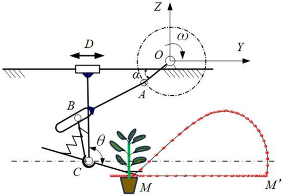
Figure 15.
Schematic diagram of the principle and trajectory of the automatic seedling-picking and depositing mechanism.
2.6. Pneumatic System Design
The step-feed of the automatic tray-feeding mechanism and the opening and closing of the seedling-picking claws are based on pneumatic principles [26,27,28,29,30]. The pneumatic system mainly comprises actuating cylinders, air circuits, trigger cams, and mechanical pneumatic control valves. Specifically, the oscillating roller of a mechanical pneumatic control valve cooperates with the cam on the transmission shaft. The lift and return strokes of the cam control the step-feeding of the automatic tray-feeding mechanism. Another mechanical pneumatic control valve controls the opening and closing of the eight groups of seedling claws of the automatic seedling-picking and depositing mechanism through cam contact. The control principle of the air circuit is shown in Figure 16a.
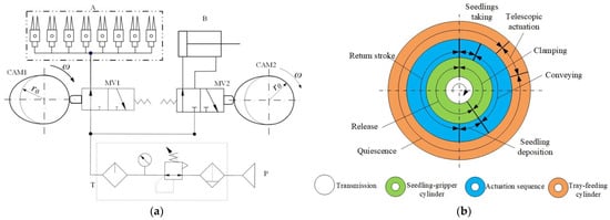
Figure 16.
Timing coordination diagram of the cylinder actions of the automatic seedling-picking claws and the tray-feeding mechanism: (a) pneumatic control diagram; (b) drive and cylinder action timing diagram. Note: P is the air source, T is the air-circuit triplet, CAM1 is the cam that controls the opening and closing of the seedling claws, CAM2 is the cam that controls the step-feed of the tray-feeding cylinder, MV1 is the two-position three-way mechanical pneumatic control valve that controls the seedling claws, MV2 is the two-position three-way mechanical pneumatic control valve that controls the tray-feeding cylinder, ω is the angular velocity of the driving shaft, A is the group of eight seedling-gripping cylinders, and B is the tray-feeding cylinder.
The air source P enters through the air-circuit triplet T and flows through two two-position four-way control valves (MV1 and MV2). Two cams mounted on the transmission shaft at different phase angles push the mechanical switches of these two control valves during rotation, resulting in periodic changes in the air circuit. One air circuit controls the opening and closing of the seedling claws, and the other controls the step-feed of the automatic tray-feeding mechanism. By designing the shapes and installation angles of the cams, the actions of the seedling-picking claws and the tray-feeding mechanism at specific positions can be precisely controlled, ensuring the smooth operation of the entire machine.
Referring to Figure 16b, with a 360° rotation angle of the driving shaft as a unified time reference, the actions of the actuating components of the automatic seedling-picking and depositing mechanism are represented by concentric rings. The innermost white ring represents the camshaft that revolves around the main shaft. The outer rings are, in order, the seedling-claw cylinder (green), the action sequence indicator ring (blue), and the seedling-tray feeding cylinder (orange). The blue ring indicates the rhythm of the working cycle of the entire machine, including five consecutive sections: seedling picking, seedling delivery, seedling depositing, standstill, and return. The green ring marks the clamping and opening phase angles of the seedling-claw cylinder during the seedling-picking and depositing stages with the labels “clamping-releasing”. The orange ring uses “extension-retraction” to represent the reciprocating stroke of the seedling-tray feeding cylinder, ensuring that a new seedling tray is delivered to the seedling-picking station at the appropriate time.
It can be seen that there is a strict one-to-one mapping between the cam profile angles and the switching moments of the pneumatic control valves, enabling the coordination of the seedling-claw cylinder and the seedling-tray feeding cylinder in space and time with a single rotation of the main shaft: When the blue seedling-picking section starts, the green ring enters the clamping section and simultaneously drives the orange ring to extend. Subsequently, when the blue enters the seedling-delivery section, the seedling claws remain clamped, and the seedling-tray cylinder completes retraction. When the blue enters the seedling-depositing section, the seedling claws open in the green releasing section to complete seedling depositing, and the seedling-tray cylinder remains in place. Finally, in the return section, the seedling claws are reset, and the orange ring prepares for the next cycle.
This timing design, through the coupling of the cam-control valve-actuating cylinder, achieves the dual advantages of mechanical rigid synchronization and pneumatic flexible adjustment, laying the foundation for high-speed and stable automatic seedling-picking and depositing operations.
This flowchart (Figure 17) illustrates the core operational logic of an automated transplanting system: A cylinder-driven ratchet mechanism achieves intermittent positioning of the seedling tray, while a crank–slider mechanism in conjunction with a rocker mechanism executes spatial positioning and orientation adjustment of seedlings. Ultimately, precise transplantation is realized through a conveyor chain-seedling cup assembly. The system forms a closed-loop kinematic chain via mechanical linkage and pneumatic control, ensuring temporal synchronization of seedling picking-lifting-placing operations.
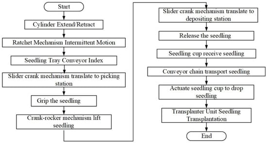
Figure 17.
Flowchart of mechanism coordination control for automated transplanting system.
2.7. Power System Design
The power source of the entire machine comes from the ground wheel, and the power transmission system is used to drive components such as the automatic seedling-picking and depositing system, the seedling-conveying system, and the planting mechanism. This system achieves power distribution through a combination of series and parallel connections, as shown in Figure 18. The ground wheel serves as the sole power input of the system. It first transmits power to chain drive II and chain drive III through chain drive I. Chain drive II is connected to the planting mechanism components, ensuring that the ground wheel and the planting mechanism rotate synchronously according to the designed transmission ratio, thereby maintaining the planting spacing. Chain drive III is connected to a T-shaped transmission box, which vertically outputs power upwards to the seedling-conveying system and achieves direction change and transmission ratio modification through external meshing gears. The power continues to be transmitted upwards to bevel gear drive II and finally to the bevel gear drives I on both sides and the crank–rocker drive through coaxial transmission, meeting the power and motion requirements of the automatic seedling-picking and depositing mechanism.
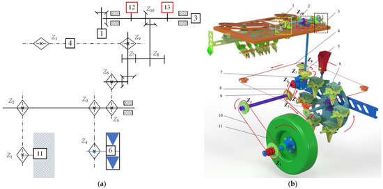
Figure 18.
Schematic diagram of the power transmission of the transplanter: (a) Schematic diagram of the overall transmission mechanism of the machine. (b) Schematic diagram of the overall transmission of the machine. 1. Bevel gear drive I; 2. bevel gear drive II; 3. crank–rocker drive; 4. seedling-cup conveying chain drive; 5. external meshing gear drive; 6. planting mechanism components; 7. transmission box; 8. chain drive III; 9. chain drive II; 10. chain drive I; 11. ground wheel; 12. tray-feeding cylinder control valve; 13. seedling-claw group gripping cylinder control valve. Note: Z1 is the number of teeth on the sprocket coaxial with the ground wheel; Z2 is the number of teeth on the input sprocket of the square shaft; Z3 is the number of teeth on output sprocket I of the square shaft; Z4 is the number of teeth on driven sprocket II of the planting mechanism; Z5 is the number of teeth on sprocket II of the square shaft; Z6 is the number of teeth on the input sprocket of the transmission box; Z7 is the number of teeth on the output gear of the transmission box; Z8 is the number of teeth on the driven gear; Z9 is the number of teeth on the output sprocket of the transmission box; Z10 is the number of teeth on the driven gear of the bevel gear.
According to the working requirements of each mechanism, the linear velocity of the seedling-cup conveying chain needs to meet the minimum transplanting frequency of 90 plants per minute specified in the standard JB/T10291-2013; Dryland Planting Machinery – Technical Conditions for Quality Inspection. China Machine Press, Beijing, China, 2013. Using Formula (4), the minimum linear velocity of the seedling-conveying mechanism can be calculated:
where vb is the minimum linear velocity of the seedling-cup conveying chain (mm/s), fm is the minimum transplanting frequency for high-speed transplanting (90 plants per minute), and c is the center-to-center distance between adjacent seedling cups (95 mm). Based on the above parameters, the calculated minimum linear velocity of seedling-cup movement is 142.5 mm/s.
Furthermore, through power transmission design, the relationship between the rotational speed of the ground wheel and the transmission ratio of the conveying chain can be expressed by Formula (5):
where vd is the minimum linear velocity of the ground wheel rotation (mm/s); vb is the minimum linear velocity of the seedling-cup conveying chain (mm/s); the transmission ratios i1 (Z1/Z2) = 26:21 and i3 (Z5/Z6) = 21:14, resulting in a ratio of 1.86:1. Substituting the minimum linear velocity of seedling-cup movement of 142.5 mm/s, the minimum linear velocity of the ground wheel is 264.6 mm/s, which is equivalent to 1 km/h when converted to units.
The transmission ratio between the seedling-conveying mechanism and the automatic seedling-picking and depositing mechanism has been precisely designed and calibrated. According to the design requirements, during one reciprocating motion of the automatic seedling-picking and depositing mechanism, the seedling-conveying mechanism should move a distance equivalent to the length of 8 seedling cups. That is, when the crank of the automatic seedling-picking and depositing mechanism rotates one full circle, the distance moved by the seedling-conveying mechanism exactly covers the spacing of 8 seedling cups.
When using a 10A chain (with a pitch of 15.875 mm), the movement distance corresponding to 6 teeth meshing between the chain and the sprocket is approximately 15.875 mm × 6 ≈ 95 mm, which is the same as the length of a single seedling cup. The sprocket Z9 has 24 teeth. When it rotates one full circle, the conveying distance is equivalent to the length of 4 seedling cups. Under the condition of the transmission ratio i4 = (Z7/Z8) = 28:56 = 1:2, for each full rotation of the bevel gear Z10, the gear Z7 will rotate twice, which in turn drives the sprocket Z9 to rotate twice accordingly, completing a total of 48-tooth meshing and conveying a distance equivalent to the length of 8 seedling cups.
This transmission scheme not only meets the minimum transplanting frequency required for high-speed transplanting operations (industry standards require a minimum transplanting frequency of 90 plants per minute for high-speed transplanters), but also ensures high-precision transmission ratios, contributing to stable and efficient transplanting operations.
2.8. Experimental Design
2.8.1. Bench Test
To evaluate the working performance of the automatic seedling-picking and depositing mechanism, a static seedling-picking and depositing test was carried out under laboratory bench conditions [31]. The test was powered by a variable-speed motor driving the ground wheel, which in turn provided power to the automatic seedling-picking and depositing mechanism. By setting different motor speeds, the seedling-picking and depositing outcomes at each speed were observed, and a relatively optimal seedling-picking and depositing speed was selected. Under different transplanting speeds, the seedling-picking success rate, seedling-depositing success rate, and the substrate loss rate during the operation were measured. Each test used a whole tray of plug-seedlings (128 plants) as the test object, and each group of tests was repeated 3 times, with the average value taken as the final result.
The tests were conducted on 14 March 2024, in the experimental plot located in Wuhaoqu Township, Yanqi Hui Autonomous County, Bayingolin Mongol Autonomous Prefecture, Xinjiang Uygur Autonomous Region, China. The plug-seedlings used in the test were standard-cultivated “Honglong23” variety pepper seedlings with 128 holes, aged 48 days, an average plant height of 194.4 mm, no damage, and with an intact substrate structure. The test power was provided by a motor, and the compressed air was supplied by a ZBM-0.1/8-B2.5P air pump with a pressure range of 0.4–0.8 MPa, which was stabilized at 0.5 MPa after being regulated by a pressure-reducing valve. The motor speed was adjusted by a Delta VFD015M43B frequency converter (Delta Electronics, Inc.; Taipei City, Taiwan). with an adjustment accuracy of 0.1 Hz.
The calculation formulas for the seedling-picking and depositing success rates are as follows:
In the following equations, N represents the number of seedlings in a single plug-tray, with the unit of plants; Nq means the number of seedlings successfully picked, with the unit of plants; Nt indicates the number of seedlings successfully planted, with the unit of plants; Aq is the seedling-picking success rate (%); At is the seedling-depositing success rate (%); Az is the overall seedling-picking and depositing success rate (%).
2.8.2. Field Experiment
To evaluate the overall working performance of the transplanter, a field transplanting experiment was conducted in Wuhaoqu Township, Yanqi Hui Autonomous County, Bayingolin Mongol Autonomous Prefecture, Xinjiang Uygur Autonomous Region, China (Figure 19). The planting soil in the experimental field was sandy loam with moisture content of 16%. The prototype machine was employed for field transplanting operations, using standard 128-hole plug-trays (Zhejiang Tianzi Co., Ltd., Wenzhou, Zhejiang, China). The seed variety was “Honglong23” with a seedling age of 50 days. The plug seedlings exhibit excellent root development within the trays, with an average substrate moisture content of 56.41%. All experimental seedlings exhibited uniform growth and no lodging, and the average plant height of the plug-seedlings was approximately 210 mm. The tractor model was John Deere 504 (Deere & Company, Moline, IL, USA), equipped with a duck-bill planter, and the air source pressure was 0.4 MPa.
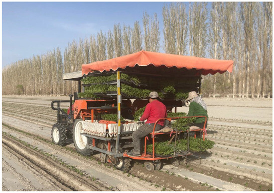
Figure 19.
Pictures of field tests.
During the experiment, the prototype machine was towed by the tractor. The transplanting speed was adjusted by modifying the tractor’s gear and the degree of throttle depression. Based on the speed ratio between the ground wheel and the transplanter, the conversion relationship between the tractor’s traveling speed and the planting frequency was calculated. Considering that the plastic-film mulching planting method is widely adopted in Xinjiang, an increase in the operating speed may lead to severe damage to the plastic film, affecting the quality of the operation [32]. According to the preliminary test results, when the planting speed exceeded 150 plants/min, the plastic-film damage became significant and could no longer meet the production requirements. Therefore, this experiment set three planting speed levels: 90 plants/min, 120 plants/min, and 150 plants/min. Single-row field transplanting experiments were carried out at each speed level. At each speed, 128 seedlings were transplanted, and each speed-level experiment was repeated three times with alternating observation and recording of the operation conditions. The experimental indicators included the overall seedling-picking and depositing success rate, the planting success rate, and the transplanting success rate, which were calculated according to the following formulas [33].
In the formula, N represents the actual number of plug-seedlings in a single plug-tray, with the unit of plants; Nt denotes the number of plug-seedlings successfully picked and planted, with the unit of plants; Nz indicates the number of plug-seedlings successfully planted, with the unit of plants; η1 is the success rate of seedling picking and depositing (%); η2 is the planting success rate (%); η is the transplanting success rate (%).
3. Results and Discussion
3.1. Bench Test Results and Discussion
Bench tests and field tests are designed to evaluate performance at different levels. Bench tests, conducted in a controlled environment, focus on verifying the limit performance and reliability of the seedling picking and depositing mechanism itself; whereas field tests are used to assess the comprehensive operational effectiveness of the fully integrated machine under real-world agronomic conditions. The test conditions necessarily differ due to their distinct purposes.
This study verified the performance of the automatic seedling-picking and depositing mechanism at different transplanting speeds through bench tests. Three groups of transplanting speeds (100, 150, and 200 plants/min) were set up (the 100 plants/min group aligns with industry-standard requirements, while the 200 plants/min group represents the maximum impact resistance capacity of the mechanism during bench test), with each group repeated three times (a total of nine tests). The seedling-picking success rate (Aq), seedling-planting success rate (At), and overall success rate (Az) were recorded. The test results were shown in Table 3.

Table 3.
Test results of the automatic seedling-picking and depositing mechanism.
As shown in Table 3 and Figure 20, under conditions without external impacts and vibrations, when the automatic seedling-Picking and depositing mechanism performs seedling-Picking and depositing actions at different speeds, the overall success rate is relatively high. However, the test outcomes demonstrate a nonlinear correlation between the operational speed and the performance of the automatic seedling-Picking and depositing mechanism. Notably, the maximum overall success rate (Az) of 98.44% is attained at an operational speed of 150 plants/min. In comparison, the performance at 100 plants/min, with an overall success rate (Az) of 97.40%, is marginally inferior, despite the lower speed.
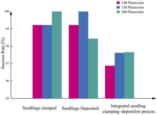
Figure 20.
Statistical chart of seedling picking and depositing success rates within different transplanting speed ranges in the bench test of the automatic seedling picking and depositing mechanism.
This observed behavior can be ascribed to the dynamic coordination between the seedling-picking mechanism and the conveying system. At 150 plants/min, the system functions in close proximity to its resonant or optimal kinematic matching state. In this state, the motion profiles of the crank–rocker and crank–slider mechanisms are optimally synchronized with the seedling tray conveyor. Such synchronization effectively minimizes the relative velocity between the picking claw and the seedling cup during their engagement, thereby reducing seedling disturbance and enhancing both the Picking and depositing precision.
Conversely, at 100 plants/min, although the speed is relatively low, the inertia of the mechanism is insufficient to sustain stable dynamic contact. The decreased operating frequency may give rise to incomplete actuation or a slight timing delay in the transmission chain, especially in the gear-rack and track-guided systems. This leads to sub-optimal claw positioning and a slight increase in misalignment during seedling extraction, as evidenced by the marginally lower seedling-picking success rate (Aq) and seedling-planting success rate (At) values.
At an operational speed of 200 plants/min, the success rate experiences a significant decline. This is attributed to the enhanced inertial forces and vibrations, which disrupt the precise trajectory of the picking claw. The higher acceleration and deceleration of the mechanism introduce timing errors and mechanical oscillations, resulting in missed picks and inaccurate planting.
Consequently, the peak performance at 150 plants/min suggests that the mechanism is kinematically and dynamically optimized for this speed range, achieving a balance between inertia, synchronization, and control responsiveness. This result emphasizes the significance of motion-coupling design in high-speed transplanting systems, where the optimal performance is not necessarily achieved at the lowest speed but rather at the speed that best aligns with the system’s inherent dynamic characteristics.
The one-way ANOVA indicates that the F-value is 11.65 and the p-value is 0.0086 (<0.05). This shows that different transplanting speeds have statistically significant differences in success rates. There is a strong correlation between transplanting speed and success rate, and the downward trend is reproducible (the standard deviations of all 9 tests are <2%).
3.2. Field Test Results and Discussion
The field operation results of the pepper automatic transplanter at different planting speeds (90 plants/min, 120 plants/min, and 150 plants/min) are presented in Table 4.

Table 4.
Field test results of the pepper automatic transplanter.
As shown in the field test results in Table 4, under different planting speed conditions, the automatic seedling-picking and Depositing system can complete various actions according to the design requirements and meet the work demands of high-speed transplanting. The trend of the test results is consistent with that of the bench test. As the planting speed increases, the success rate of seedling picking and depositing shows a downward trend. Regarding the planting success rate, although an increase in planting speed leads to a decrease in the planting success rate, the overall level remains relatively high. With the increase in planting speed, the overall transplanting success rate shows a significant downward trend. The test data further show that when the transplanting speed reaches 150 plants/min, the success rates of seedling picking and depositing and planting decrease to 92.61% and 96.29%, respectively, and the overall transplanting success rate drops below 90%. This indicates that an excessively high planting speed causes significant changes in the throwing and falling trajectories of the plug-seedlings, making them prone to collisions with adjacent components and thus affecting the transplanting success rate.
The one-way ANOVA results show that the F-value is significantly higher than the critical value (F = 74.92), and the corresponding p-value (5.71 × 10⁻⁵) is much smaller than the significance level of 0.01. These statistical results indicate that there are highly significant differences in the transplanting success rates among different planting speed treatment groups (p < 0.01), verifying the significant impact of planting speed as a key factor on transplanting quality.
Compared with the bench test, the success rates of seedling picking and depositing at different planting speeds in the field test all declined, especially at a planting frequency of 150 plants/min, where the success rate was only 92.61%. Specifically, during the seedling-planting process, plug-seedlings often got stuck on the seedling cups or fell outside the edges of the seedling cups. The main reasons for this difference lie in the relatively low stability of the machine’s movement during the field test and the influence of external factors such as wind, which resulted in unsatisfactory seedling-planting effects.
In addition, in the field test, the planting success rate also showed a downward trend, which was particularly significant when the planting frequency reached 150 plants/min. During the test, there were cases where seedling cups fell to the edge or outside of the duck-bill of the planter. The main reasons were the relatively large height difference between the plug-seedlings and the planter, and the influence of factors such as wind and inertia, which led to low accuracy in accurately depositing the seedlings into the planter. This observed decline in performance at increased operational speeds is consistent with findings in other studies on transplanting systems [34,35].
The transplanting success rate obtained from the field test verified the feasibility of the principles of each mechanism, indicating that relevant components (such as mechanisms, transmission systems, and pneumatic systems) could effectively cooperate, ensuring the practical application effect of the whole machine system in the field environment. This transplanter could meet the functional requirements of high-speed automatic transplanting and guarantee the transplanting quality to a certain extent.
4. Conclusions
The core working principle of the designed follow-up mechanism—synchronization to eliminate relative error—is universal. However, its current specific design is primarily targeted at pepper plug seedlings of similar size. Application to other crops (e.g., eggplant, tomato, and other Solanaceae crops) would require re-adaptation and optimization of the claws, the trajectory of the separating mechanism, and the seedling cup dimensions based on the specific tray specifications (cell size and depth) and seedling morphology (height and stem diameter). Future research could focus on developing an adjustable, modular mechanism to enhance its universality.
This study successfully designed and validated an automatic transplanting machine specifically for 128-cell pepper plug seedlings. The core achievement was the development of a follow-up seedling picking and depositing mechanism that fundamentally addressed the conflict between high-speed operation and planting accuracy by synchronizing the motion of the picking claws with the moving seedling cups, thereby enabling spatially stationary depositing. Key findings and conclusions derived from this work are as follows:
The integrated mechanical transmission system, powered by the ground wheel and synchronized via chains and gears, proved to be a robust solution for coordinating the automatic tray-feeding, seedling conveying, and planting mechanisms. This design significantly enhanced the operational reliability and transplanting quality of the entire machine under controlled conditions.
However, this study also revealed specific limitations that impact performance. The relatively complex transmission architecture demands high manufacturing and assembly precision. Furthermore, the dependence on ground wheel traction introduced inherent variability; friction-induced slippage caused unpredictable speed fluctuations in the transmission chain, leading to disruptive impacts and vibrations that adversely affected the consistency of the transplanting effect.
Bench and field tests quantitatively demonstrated that the overall planting frequency is constrained not by the picking and depositing mechanism itself—which performed optimally at higher speeds—but by the subsequent planting mechanism. The planter’s operational speed emerged as the systemic bottleneck, limited by the intrinsic kinematic characteristics of the overall machine structure. Consequently, to achieve a further increase in transplanting speed, future efforts must focus on the optimization of the planter’s structure or a fundamental simplification of the workflow from seedling picking to ground planting.
In summary, this research provides a validated mechanical solution for high-speed, precision transplanting of pepper plug seedlings, the planting efficiency is higher than that of similar products [35]. The identified performance boundaries and bottlenecks offer critical insights and a clear direction for the next stage of development in high-speed automated transplanting technology. Although the picking and depositing mechanism itself performs excellently at high speeds, the overall field performance at extremely high speeds is limited by the subsequent planting process. Future research will focus on integrating precision agriculture technologies, such as developing machine vision-based monitoring systems for cup position or inertial sensor-based real-time control systems for planting depth, to optimize the coordination between the planter and the forward speed, thereby further enhancing the comprehensive success rate under high-speed operation.
Author Contributions
Conceptualization, G.L. and J.L.; methodology, C.H. and H.M.; software, G.L.; validation, G.L. and Y.X.; formal analysis, G.L. and J.L.; data curation, G.L. and Y.L.; writing—original draft preparation, G.L. and C.H.; writing—review and editing, G.C., H.M., and C.H.; supervision, C.H., H.M., and G.C.; project administration, C.H. and J.L.; funding acquisition, C.H. and G.L. All authors have read and agreed to the published version of the manuscript.
Funding
This research was funded by the National Natural Science Foundation of China (50905153, 51565059); the Key Research and Development Program of Xinjiang Uygur Autonomous Region (2023B02021-2); the Xinjiang Uygur Autonomous Region Tian Shan Innovation Team Project (2021D14010); the “Tian Shan Talents” Cultivation Program of the Xinjiang Uygur Autonomous Region (2024TSYCCX0035); the XJARS—Vegetables (XJARS-07-06); the Natural Science Foundation of Xinjiang Uygur Autonomous Region (2022D01A323).
Institutional Review Board Statement
Not applicable.
Data Availability Statement
Data are contained within the article.
Conflicts of Interest
Author Jia Liang serves as engineer at Bazhou Liangjia Agricultural Machinery Manufacturing Co., Ltd. The company was not involved in the study design, data collection, analysis, or interpretation. All other authors declare no competing financial interests or personal relationships that could influence the research.
References
- Zhou, M.; Sun, H.; Xu, X.; Yang, J.; Wang, G.; Wei, Z.; Xu, T.; Yin, J. Study on the Method and Mechanism of Seedling Picking for Pepper (Capsicum annuum L.) Plug Seedlings. Agriculture 2024, 14, 11. [Google Scholar] [CrossRef]
- Wu, G.; Wang, S.; Zhang, A.; Xiao, Y.; Li, L.; Yin, Y.; Li, H.; Wen, C.; Yan, B. Optimized design and experiment of a self-covering furrow opener for an automatic sweet potato seedling transplanting machine. Sustainability 2023, 15, 13091. [Google Scholar] [CrossRef]
- Yu, G.; Wang, L.; Sun, L.; Zhao, X.; Ye, B. Advancement of mechanized transplanting technology and equipments for field crops. Trans. Chin. Soc. Agric. Mach. 2022, 53, 1–20. [Google Scholar]
- Khadatkar, A.; Sawant, C.P.; Magar, A.P.; Kumar, V. Agricultural robots and automated machinery for handling of nursery seedlings with special reference to the transplanting devices. Discov. Appl. Sci. 2025, 7, 916. [Google Scholar] [CrossRef]
- Sun, L.; Xu, H.; Zhou, Y.; Shen, J.; Yu, G.; Hu, H.; Miao, Y. Kinematic Synthesis and Simulation of a Vegetable Pot Seedling Transplanting Mechanism with Four Exact Task Poses. Int. J. Agric. Biol. Eng. 2023, 16, 85–95. [Google Scholar] [CrossRef]
- Yang, J.; Zhou, M.; Yin, D.; Yin, J. Design and development of rice pot-seedling transplanting machinery based on a non-circular gear mechanism. Appl. Sci. 2024, 14, 1027. [Google Scholar] [CrossRef]
- Hu, S.; Hu, M.; Zhang, W. Design and Experiment of Flexible Clamping Device for Pepper Plug Seedlings. Adv. Mech. Eng. 2022, 14, 16878132221107254. [Google Scholar] [CrossRef]
- Sharma, A.; Khar, S. Design and development of a vegetable plug seedling transplanting mechanism for a semi-automatic transplanter. Sci. Hortic. 2024, 326, 112773. [Google Scholar] [CrossRef]
- Khadatkar, A.; Pandirwar, A.P.; Paradkar, V. Design, Development and Application of a Compact Robotic Transplanter with Automatic Seedling Picking Mechanism for Plug-Type Seedlings. Sci. Rep. 2023, 13, 1883. [Google Scholar] [CrossRef] [PubMed]
- Markumningsih, S.; Seok-Joon, H.; Jeong-Hun, K.; Moon-Kyeong, J.; Ju-Seok, N. Stress Simulation on Four-Bar Link-Type Transplanting Device of Semiautomatic Vegetable Transplanter. Agriculture 2024, 14, 42. [Google Scholar] [CrossRef]
- Cao, X.; Wang, Q.; Li, H.; He, J.; Lu, C.; Xu, D.; Wang, X. Design and Experiment of the Pneumatic Pressure Control Device for No-till Planter. Int. J. Agric. Biol. Eng. 2023, 16, 37–46. [Google Scholar] [CrossRef]
- Wang, Y.; He, Z.; Wang, J.; Wu, C.; Yu, G.; Tang, Y. Experiment on transplanting performanceof automatic vegetable pot seedling transplanter for dry land. Trans. Chin. Soc. Agric. Mach. 2018, 34, 19–25. [Google Scholar]
- Yan, H.; Liu, C.; Li, P.; Chen, R.; Zhou, H.; Zhuang, T. Design and Experiment of Duckbill Planting Device with Adjustable Static Trajectory for Planting Vegetable Transplanters. Trans. Chin. Soc. Agric. Mach. 2023, 54, 71–81. [Google Scholar]
- Han, C.; Yang, W.; Zhang, X.; Guo, H.; Yin, W. Design and test of automatic feed system for tray seedlings transplanter. Trans. CSAE 2013, 29, 51–61. [Google Scholar]
- Wen, Y.; Zhang, J.; Yuan, T.; Tan, Y. Current situation and analysis of automatic pick-up technology for vegetable plug seedlings. J. China Agric. Univ. 2021, 26, 128–142. [Google Scholar]
- Parish, R. Current developments in seeders and transplanters for vegetable crops. HortTechnology 2005, 15, 346. [Google Scholar] [CrossRef]
- Tian, Z.; Ma, W.; Yang, Q.; Yao, S.; Zhang, M.; Duan, F.; Xu, H. Research status and problem analysis of the transplanting machinery of greenhouse pot seedling. J. China Agric. Univ. 2022, 27, 22–38. [Google Scholar]
- Yu, G.H.; Wang, X.L.; Liu, J.G.; Ye, B.L.; Li, X.; Zhao, X. Design and Experiment of Multi Row Seedling Taking Mechanism for Dense Planting and Transplanting of Vegetable Pot Seedlings. Trans. Chin. Soc. Agric. Mach. 2023, 54, 94–103. [Google Scholar]
- Cao, L.; Liu, C.; Zhang, C. Structure Design and Simulation of Plug-Seedling Gripping Device. In Proceedings of the 2016 International Conference on Mechanics, Materials and Structural Engineering (ICMMSE), Jeju Island, Republic of Korea, 18–20 March 2016; pp. 50–54. [Google Scholar]
- Yao, M.; Hu, J.; Liu, W.; Shi, J.; Jin, Y.; Lv, J.; Sun, Z.; Wang, C. Precise Servo-Control System of a Dual-Axis Positioning Tray Conveying Device for Automatic Transplanting Machine. Agriculture 2024, 14, 1431. [Google Scholar] [CrossRef]
- Tong, J.; Qiu, Z.; Zhou, H.; Bashir, M.K.; Yu, G.; Wu, C.; Du, X. Optimizing the Path of Seedling Transplanting with Multi-End Effectors by Using an Improved Greedy Annealing Algorithm. Comput. Electron. Agric. 2022, 201, 107276. [Google Scholar] [CrossRef]
- Wen, Y.; Zhang, Y.; Tian, J.; Yuan, T.; Zhang, J.; Tan, Y. Design and experiment of vegetable transplanting pot seedling detection and missing seedling compensation system. Trans. Chin. Soc. Agric. Mach. 2020, 51, 124–125. [Google Scholar]
- Zhang, Z. Current status and technical key points of industrial chili pepper cultivation in Yanqi County, Xinjiang. Agric. Eng. Technol. 2023, 43, 84–85. [Google Scholar]
- Rasool, K.; Ali, M.; Chowdhury, M.; Kwon, H.J.; Swe, K.M.; Chung, S.O. Theoretical analysis of velocity, acceleration and torque calculation of a five-bar onion transplanting mechanism. IOP Conf. Ser. Earth Environ. Sci. 2021, 733, 012019. [Google Scholar] [CrossRef]
- Ye, B.; Zeng, G.; Deng, B.; Yang, C.; Liu, J.; Yu, G. Design and Tests of a Rotary Plug Seedling Pick-up Mechanism for Vegetable Automatic Transplanter. Int. J. Agric. Biol. Eng. 2020, 13, 70–78. [Google Scholar] [CrossRef]
- Chen, B. Research on Automatic Seedling Supply Device of Chili Pot Seedling Transplanter. Ph.D. Thesis, Hunan Agricultural University, Changsha, China, 2023. [Google Scholar]
- Zhou, B.; Miao, H.; Guan, C.; Ji, X.; Wang, X. Design and Test of Seedling-Picking Mechanism of Fully Automatic Transplanting Machine. Appl. Sci. 2024, 14, 9235. [Google Scholar] [CrossRef]
- Du, F.; Liu, J.; Qi, P. Research on the Seedling Picking Trajectory Error of the Gear Train Seedling Picking Mechanism Considering Tooth Backlash. Eng. Rep. 2024, 12840. [Google Scholar] [CrossRef]
- Cui, Z.C.; Guan, C.S.; Xu, T.; Fu, J.; Chen, Y.; Zhen, S. Design and Experiment of Double-Row Chain Planting Device for Cabbage Substrate Block Seedling Transplanter. Trans. Chin. Soc. Agric. Mach. 2023, 54, 46–54. [Google Scholar]
- Choi, W.C.; Kim, D.C.; Ryu, I.H.; Kim, K.U. Development of a Seedling Pick-up Device for Vegetable Transplanters. Trans. Am. Soc. Agric. Eng. 2002, 45, 13–19. [Google Scholar]
- Zhou, T. Design and Experiments of An Arc Expansion Type Automatic Seedling Taking and Throwing Device for Vegetable Plug Seedlings. Master’s Thesis, Xinjiang Agriculture University, Urumqi, China, 2023. [Google Scholar]
- Xiao, L.Q. Design and Experiment of High-Speed Automatic Transplanting Machine for Plug Seedlings. Master’s Thesis, Xinjiang Agriculture University, Urumqi, China, 2023. [Google Scholar]
- Ma, G.; Mao, H.; Zhang, K.; Gao, F.; Liu, Y.; Han, L. Design of a whole row pneumatic seedling pick-up device for fully-automatic field transplanters with reciprocating movement and intelligent control system. In Proceedings of the ASABE Annual International Meeting, Boston, MA, USA, 7–10 July 2019; American Society of Agricultural and Biological Engineers: St. Joseph, MI, USA; p. 1. [Google Scholar]
- Yang, Q.; Huang, G.; Shi, X.; He, M.; Ahmad, I.; Zhao, X.; Addy, M. Design of a control system for a mini-automatic transplanting machine of plug seedling. Comput. Electron. Agric. 2020, 169, 105226. [Google Scholar] [CrossRef]
- Zhao, S.; Liu, J.; Jin, Y.; Bai, Z.; Liu, J.; Zhou, X. Design and Testing of an Intelligent Multi-Functional Seedling Transplanting System. Agronomy 2022, 12, 2683. [Google Scholar] [CrossRef]
Disclaimer/Publisher’s Note: The statements, opinions and data contained in all publications are solely those of the individual author(s) and contributor(s) and not of MDPI and/or the editor(s). MDPI and/or the editor(s) disclaim responsibility for any injury to people or property resulting from any ideas, methods, instructions or products referred to in the content. |
© 2025 by the authors. Licensee MDPI, Basel, Switzerland. This article is an open access article distributed under the terms and conditions of the Creative Commons Attribution (CC BY) license (https://creativecommons.org/licenses/by/4.0/).