Article

Design and Experiment of Air–Fertilizer Separator for Pneumatic Deep Fertilization in Paddy Fields

1
College of Engineering, Shenyang Agricultural University, Shenyang 110866, China
2
School of Agricultural Engineering, Jiangsu University, Zhenjiang 212013, China
*
Author to whom correspondence should be addressed.
Agriculture 2025, 15(18), 1991; https://doi.org/10.3390/agriculture15181991
Submission received: 21 August 2025 / Revised: 17 September 2025 / Accepted: 20 September 2025 / Published: 22 September 2025
(This article belongs to the Section Agricultural Technology)

Abstract

Supplemental fertilizer application is critical for improving rice yield. Pneumatic deep fertilization effectively improves fertilizer utilization, but high-speed airflow may disturb the soil and affect the location of the fertilizer particles. An air–fertilizer separator was developed in this study to separate the fertilizer from the airflow before the two-phase flow rushes into the soil, and the airflow is directed away from the surface of the paddy soil. The structural and operating parameters of the air–fertilizer separator are determined in this paper. A quadratic orthogonal rotation combination experiment was conducted, taking structural parameters of the device as variables, and fertilizer injection speed, separation loss rate, and outlet airflow speed as performance indicators, to optimize the design parameters of the air–fertilizer separator. The variance analysis and surface response analysis of the experimental data are conducted, and the mathematical models between the indicators and the influencing factors are established. The optimal parameters were determined using multi-objective optimization, and the experimental verification was carried out. The optimal parameters for the air–fertilizer separator were obtained as an arc radius of the AFAST of 380 mm, central angle of arc trough of 45°, and depth of primary separation arc-trough of 12.5 mm. The validation experimental results show that the fertilizer injection speed is 21.45 m/s, the fertilizer separation loss rate is 10.22%, and the outlet airflow speed is 42.54 m/s. The experimental values are close to the predicted values, with errors of 1.2%, 1.7%, and 1.3%. The results of the study may provide a reference for the development of an air–fertilizer separator for pneumatic deep fertilization in paddy fields.

1. Introduction

Rice is an important food crop, and its yield stability is directly related to global food security [1]. Supplementary application of fertilizer can ensure a continuous supply of nutrients during the growth of rice, and it is one of the important measures to increase rice yield [2]. Broadcasting is the most common method for rice fertilizer application [3,4], but there are problems such as a low fertilizer utilization rate and uneven distribution of fertilizer particles in the field [5]. Compared with broadcast fertilization, deep fertilization of rice can save about 10% of fertilizer and increase the fertilizer utilization rate by over 50% [6]. Deep fertilization can greatly improve the nutrient environment of the paddy field and reduce water pollution.
Research on deep fertilization devices mainly focuses on synchronous side-deep fertilization during rice transplantation [7,8] and direct seeding [9,10]. In terms of deep fertilization research, some manually operated deep fertilization devices for rice seedlings were developed [11,12]. Wang Jinfeng and his team developed an electric two-row deep fertilization and weeding machine for paddy fields [13]; Southeast Asian countries employ the practice of super-granular urea (USG) deep placement in rice production and have developed some related machines [14,15]. In 2009, Wohab developed a deep placement machine (BARI) for large-particle urea [16]. Since then, some scholars have improved the BARI and developed other machines with similar working principles [17,18,19,20,21]. Most of the above devices used a mechanical furrow opener, and there are problems such as sludge sticking in the opener and blockage of fertilizer at the outlet [22].
As for pneumatic fertilizer application, Zuo Xingjian designed an air-blast rice side-deep precision fertilization device [23]. Li Liwei conducted two-phase flow simulations of the pneumatic-conveying fertilizer feeder of a rice fertilizer applicator [24]. These deep fertilizer application devices are to inject fertilizer and fluid into the paddy field together, and the high-speed airflow may disturb the soil and it may escape from the muddy soil, resulting in the shift of fertilizer with the fluid, decreasing the quality of fertilization.
Therefore, an air–fertilizer separator for the pneumatic deep fertilization in paddy fields was designed in this study, which diverts the air out before the two-phase air–fertilizer flow into the paddy soil, to reduce the impact of the airflow on the slurry soil. Kinetic analysis and experimental study of fertilizer particles in the air–fertilizer separator were carried out to determine and optimize the structural parameters.

2. Materials and Methods

2.1. Structure and Working Process of Pneumatic Deep Fertilization Device for Rice

A pneumatic deep fertilization device for paddy fields was developed, as shown in Figure 1, which mainly consists of an air supply system, a profiling mechanism, a fertilizer metering system, a fertilizer feeding port, a fertilizer speeding tube, a water divider, and an air–fertilizer separator.
During operation, the fertilizer particles are metered from the fertilizer metering system, mixed with the high-pressure airflow from the air supply system at the air–fertilizer mixing interface, and then accelerated in the acceleration tube. Before the two-phase flow of air–fertilizer enters the soil, the air–fertilizer separator separates and diverts the airflow to the atmosphere, and the high-speed fertilizer particles penetrate into the slurry soil, where surface water has been swept away by the water divider. The soil then falls back to cover the fertilizer.
The air–fertilizer separator consists of an air–fertilizer separation arc-shaped tube (AFAST) connected with the fertilizer acceleration tube, an arc-shaped trough that is the extension and half of the separation tube, and two air-diverting arc plates that are set at both ends and the top of the trough.
When the accelerated fertilizer particles with airflow rush into the separation arc-tube and arc-shaped trough, they will run closer to the back wall of the separation tube and trough under the action of centrifugal force, so the fertilizer and airflow separate since the fertilizer is denser than air; the airflow is directed away by the two arc-shaped air diverting plates mounted at the beginning and end of the trough. The fertilizer moves along the arc-shaped trough, until it leaves the trough and penetrates into the soil.

2.2. Parameter Design of Air–Fertilizer Separator

2.2.1. Structural Design and Parameter Determination of the Air–Fertilizer Separator

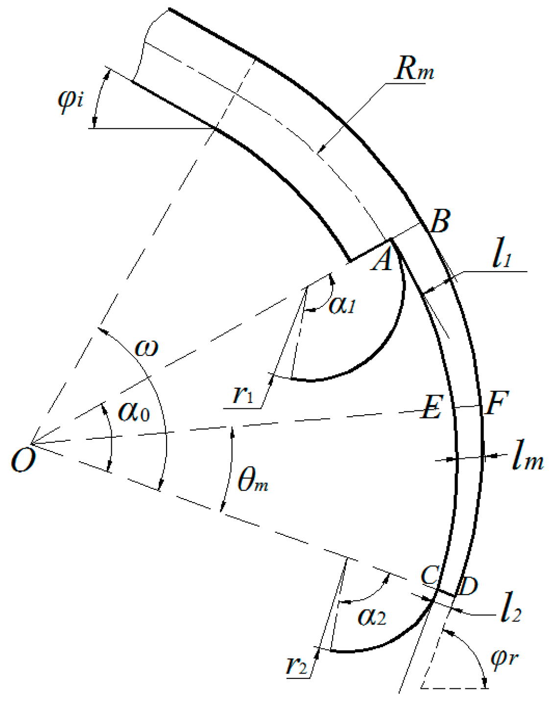
The air–fertilizer separator was designed and the main structural parameters are shown in Figure 2.
The separator is tilted at φi = 30° to ensure the vertical free-fall of fertilizer from the fertilizer discharge system into the air–fertilizer mixing interface.
The included angle (φr) between the fertilizer trajectory into the soil and the soil surface should not be less than 60° [25], to ensure the depth of the fertilizer into the soil. The φr is set as 70° in this study. The central angle ω of the separator is 80° according to the geometric relationship.
OF is the bisector of the central angle of the arc-shaped trough. Point E is located on the line segment OF. The length of EF is half of the sum of the depths of arc-shaped troughs l1 and l2. In cutting off the inner part along the circular path through points A, E, and C, the resultant arc-shaped trough is made to match the requirements of the outlet dimensions and central angle.
Air-diverting arc plates are installed at the beginning and end of the arc-shaped trough. The primary air–fertilizer outlet AB and the secondary air–fertilizer outlet CD are formed by the arc plate and the arc-shaped trough. The depths of the arc-shaped troughs at the two air–fertilizer outlets are defined as the primary arc-trough depth (l1) and the secondary arc-trough depth (l2).
The air-diverting plate is designed with a curved arc structure to guide the airflow away from the soil surface, to avoid disturbance of the paddy soil. The radius of the primary air-diverting arc plate r1 is designed as 70 mm, the radius of the secondary air-diverting arc plate r2 is designed as 50 mm, and the tangent at the end of the two air-diverting arc plates forms an angle of 10° with the horizontal line. According to geometric relations, the center angle α1 of the primary air-diverting arc plate and the center angle α2 of the secondary air-diverting arc plate are as follows:
α 1 = α 0 + φ r + 10 °
α 2 = φ r + 10 °
where α0 is the central angle of the arc-shaped trough, rad.
According to Formula (1), the central angle of the primary air-diverting arc plate should be adjusted with the central angle of the arc-shaped trough; the angle of the secondary air-diverting arc plate is 80° when φr is 70°.

2.2.2. Determination of the AFAST Diameter

The diameter of air–fertilizer arc-shaped tube (AFAST) is as follows [23]:
D = 4 Q π v a
where Q is the airflow rate, m3/s; va is the air speed, m/s.
Assuming the air leakage rate of the system is 10%, the airflow rate Q can be calculated as follows:
Q = 1.1 b v m q 10000 μ γ
where b is the rice row spacing, m; vm is the forward speed of the fertilization machine, m/s; q is the application rate of the fertilizer, kg/hm2; μ is the mixing concentration ratio; and γ is the air volume weight, kg/m3.
The conveying air speed of a pneumatic fertilization system is calculated as follows:
v a = K v f
where va is the air speed, m/s; K is the speed coefficient, set to 6 in this study; and vf is the terminal speed of fertilizer, m/s.
According to the pre-test, the terminal speed of large urea particles is 6.98–9.09 m/s [26]. The row spacing of rice is 300 mm, the set working speed of the pneumatic deep fertilization machine is 1.5 m/s, the fertilization rate is 150 kg/hm2 [13], and the material-to-air concentration ratio μ in the pneumatic fertilization system is generally taken as 0.5 [27]. Then, the inner diameter (D) of the AFAST can be worked out as according to Equation (3), and it is determined as 25 mm in this study.

2.2.3. Arc Radius of the AFAST

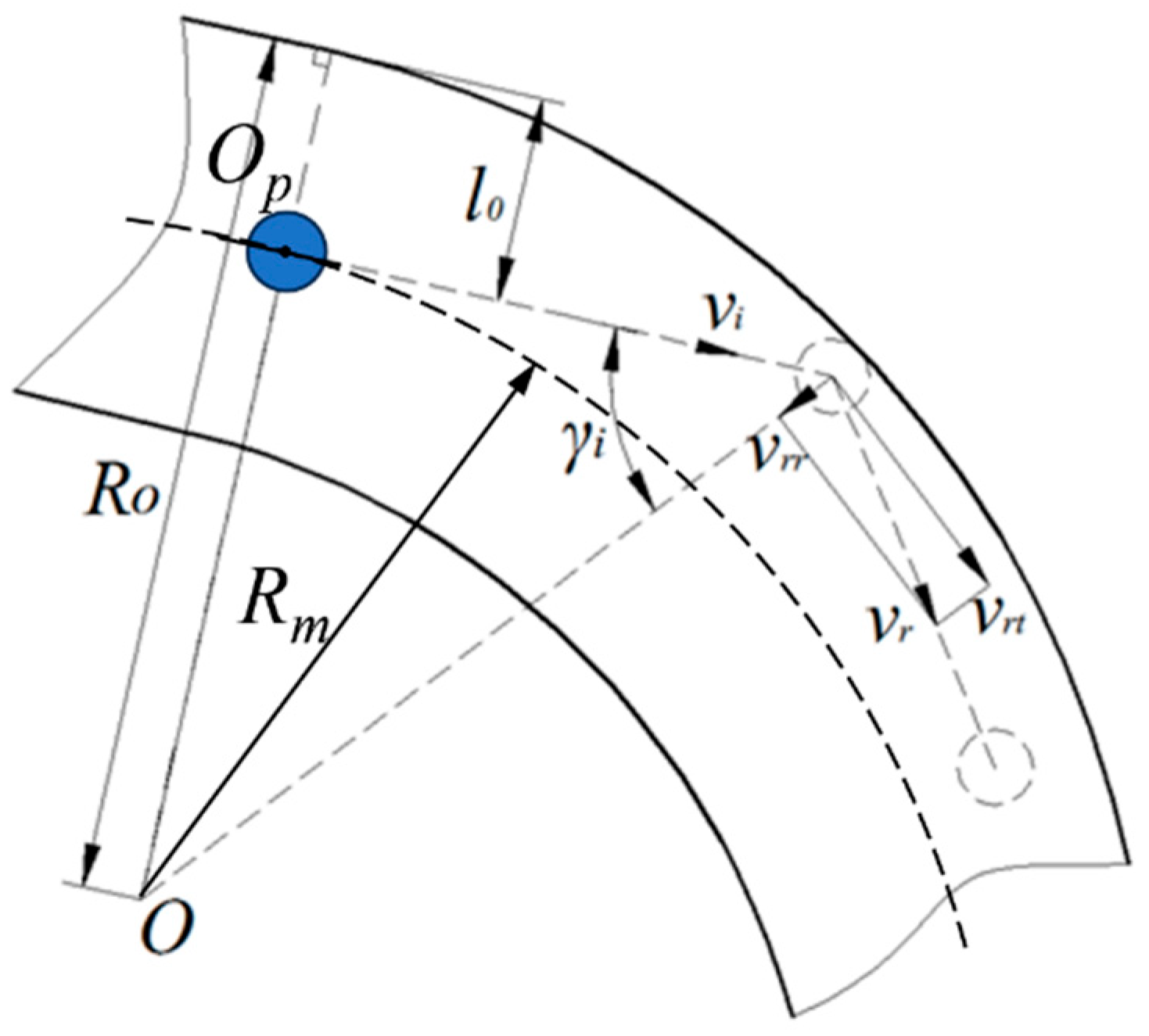
The arc radius of the AFAST (Rm) affects the centrifugal force of the fertilizer particles, so as to affect the air–fertilizer separation. The kinematic analysis of fertilizer particles in the AFAST is shown in Figure 3.
The higher the incident speed, the better the air–fertilizer separation performance. However, the incident speed vi should be less than the critical impact speed vl of the fertilizer particles for a better separation, and vl is the incident speed for vertical injection of fertilizer particles. The granular fertilizers in common use are classified as brittle materials and can be regarded as elastic materials before breakage [28]. The peak impact stress σmax of brittle particle-wall collisions, according to Hertz contact mechanics, can be expressed as follows [29,30]:
σ max = 3 2 π 4 E * 3 R e 3 4 2 3 5 m e v e 2 4 1 15
where me is the equivalent mass of the collision object, kg; E* is the equivalent elastic modulus of the collision object, Pa; Re is the equivalent diameter of the collision object, m; and ve is the impact speed, m/s.
The critical impact speed (vl) at which the fertilizer particles break upon normal collision with the wall of the AFAST can be expressed as follows:
v l = 1.56 σ l 5 ρ E p 4
where σl is the critical impact stress for fertilizer particle breakage, Pa; Ep is the equivalent elastic modulus of fertilizer and materials of the air–fertilizer separator, Pa; and ρ is the density of the fertilizer, kg/m3.
The equivalent elastic modulus Ep [31] is as follows:
1 E p = 1 - μ f 2 E f + 1 - μ t 2 E t
where Ef is the elastic modulus of the fertilizer particles, Pa; Et is the elastic modulus of the material of the air–fertilizer separator, Pa; μf is the Poisson’s ratio of the fertilizer particles; and μt is the Poisson’s ratio of the material of the air–fertilizer separator.
In order to avoid breakage of the fertilizer when entering the air–fertilizer separator, the incident speed of the fertilizer should meet the following condition:
v i v l cos arcsin R o l 0 R o
According to Equation (9), it can be determined that when l0 is equivalent to the inner diameter of the acceleration tube (D), and the angle γi is minimal, the fertilizer is most susceptible to breaking. To prevent breakage of the fertilizer, the arc radius of the AFAST (Rm) should meet the following relationship:
R m v i D v l 2 v i + v i 2 v l 2
where D is the inner diameter of the AFAST, m.
The property parameters [26,32] of the fertilizer granules (urea) used in this study and the air–fertilizer separator material (PMMA) are shown in Table 1.
In the case of brittle materials, the critical impact stress for particle breakage (σl) can be regarded as being equivalent to the ultimate compressive stress [33]. According to previous experiments, the ultimate compressive stress of fertilizer used in this study is 36.66 MPa [26].
The final injection speed of fertilizer at the outlet should be 18–25 m/s to ensure the depth of fertilization [34]. Considering the speed loss during the movement, the incident speed vi of the fertilizer is set to 30 m/s to ensure sufficient injection speed. According to Equation (10) and known parameters, the arc radius of the AFAST (Rm) should be greater than 162 mm.
It can be observed from Figure 2 that the small arc radius of the AFAST (Rm) will result in an increase in centrifugal force, which may cause the fertilizer to collide with the wall of the tube. Considering the overall structure and motion stability, Rm is set as 330 mm.
According to pneumatic conveying theory, the maximum speed of fertilizer particles after being accelerated in a straight tube is as follows [35]:
v p max = v i 0.6 v a
where vpmax is the maximum speed of fertilizer particles after pneumatic acceleration, m/s.
According to Formula (11), the airflow speed is set as 50 m/s preliminarily.
The other key structural parameters of the air–fertilizer separator are initially determined as follows: primary arc-trough depth l1 = 12 mm and secondary arc-trough depth l2 = 6 mm. The central angle of the arc-shaped trough is α0 = 40°, and the arc radius of the AFAST (Rm) is 330 mm. Under these conditions, the central angle of the primary air-diverting arc plate is 120°.

2.3. Experimental Details and Result Analysis of Air–Fertilizer Separator

2.3.1. Experimental Equipment and Materials

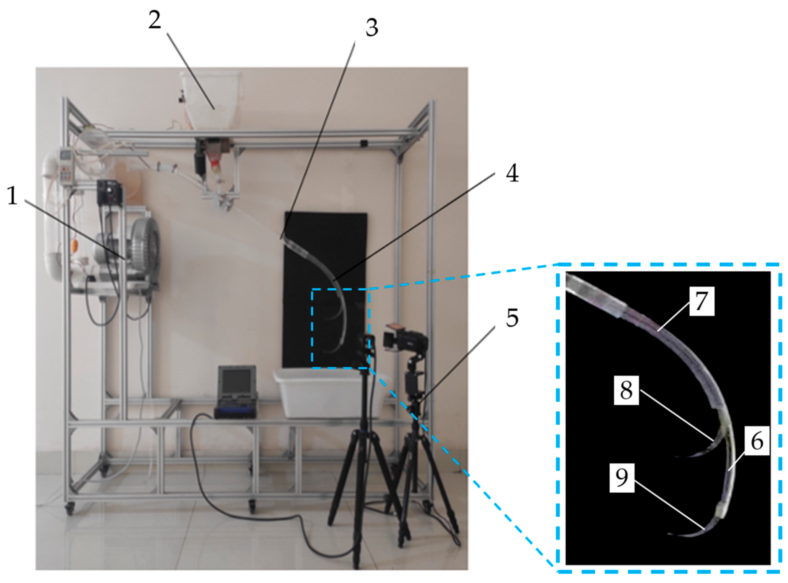
A test bench was developed, as shown in Figure 4, which consists of a high-pressure blower (XG-1500, flow rate of 250 m3/h, air pressure of 32 kPa, rated power of 1.5 kW, Chengyu Electromechanical Equipment Co., Ltd., Chendu, China), a silicon-controlled-rectifier electronic voltage regulator (DTY-4000, Wenfu Electric Co., Ltd., Wenzhou, China), an anemometer (YIOU ZC1000-1F-9, wind speed measuring range of 1–90 m/s, accuracy of 0.01 m/s, Yiou Instrument Equipment Co., Ltd., Shanghai, China), a regulated air chamber, an electric fertilizer metering mechanism, a PLEXLOGGER high-speed dynamic image analyzer (Shinano Kenshi Co., Ltd., Nagano, Japan), a fertilizer acceleration tube, and an air–fertilizer separation mechanism (material of PMMA for easy observation).
The fertilizer used in the experiment was urea (China National Coal Group Corp., Beijing, China). Fertilizer particles with a similar mass and particle sizes were selected for the experiment and analysis. Fertilizer particles were sieved using sieves with an aperture of 4 mm and 3.2 m, respectively (Linshuo-brand sieve, with mesh apertures of 4 mm and 3.2 mm), and fertilizer particles on the 3.35 mm sieve were taken for the experiment.

2.3.2. Experimental Indicators and Test Method

(1) Fertilizer injection speed
Fertilizer injection speed affects the depth of penetration into the paddy soil. A high-speed dynamic image analyzer was used to capture the movement of fertilizer particles ejected from the secondary air–fertilizer outlet and import the image into post-processing software. The speeds of 30 random fertilizer particles were captured and the average value was calculated.
(2) Fertilizer separation loss rate
The fertilizer separation loss rate reflects the air–fertilizer separator’s performance. In this study, a high-speed dynamic image analyzer was used to record the number of fertilizer particles ejected from the secondary air–fertilizer outlet within 3 s (n1) and the number ejected from other locations (n2), and the separation loss rate ηp was calculated using Equation (12).
η p = n 2 n 1 + n 2
where n1 is the number of fertilizer particles ejected from the secondary air–fertilizer outlet, pcs; n2 is the number of fertilizer particles ejected at other locations, pcs.
(3) Outlet airflow speed
The outlet airflow speed reflects the air–fertilizer separation ability of the air–fertilizer separator. The airflow speed at the secondary air–fertilizer outlet was measured using a YIOU anemometer.

2.3.3. Experimental Design

The primary objective of the experiment was to optimize the parameters of the air–fertilizer separator according to their influence on the indicators. The arc radius of the AFAST and the central angle of the arc-shaped trough affect the centrifugal force of the fertilizer particles, so as to affect the air–fertilizer separation performance; the depth of the primary arc-trough influences both the air–fertilizer separation performance and fertilizer separation loss rate.
Therefore, quadratic orthogonal rotation combination experiments were conducted, taking the arc radius of the AFAST (X1), the central angle of the arc-shaped trough (X2), and the primary arc-trough depth (X3) as experimental factors, and the fertilizer injection speed, fertilizer separation loss rate, and outlet airflow speed were taken as evaluation indicators. The range of values for the three experimental factors was determined by preliminary single-factor experiments and theoretical analysis. The levels of the experimental factors were coded as shown in Table 2.

3. Results and Discussion

3.1. Experimental Results

The experiment arrangement and results are shown in Table 3. The data processing and analysis were performed using Design-Expert 13.

3.2. Analysis of Experimental Results

The regression models for the fertilizer injection speed (Y1), fertilizer separation loss rate (Y2), and outlet airflow speed (Y3) were all established and analyzed at the significance level of α = 0.05 (Table 4).
It can be obtained from the analysis of variance in Table 4 that all three models are highly significant (p < 0.0001), with F-values well above the critical threshold. Their multiple correlation coefficients were 0.94, 0.97, and 0.99, indicating strong agreement between the predicted and measured values. The lack-of-fit tests were not significant (p > 0.05), confirming the validity of the models for prediction.
For the fertilizer injection speed, the order of factor influence is X2 > X3 > X1; for the separation loss rate, it is X3 > X2 > X1; and for the outlet airflow speed, it is X3 > X2 > X1. After removing insignificant terms, the final regression equations for the three responses were obtained, as shown in Equation (13).
Y 1 = 37.29 - 7.13 × 10 - 3 X 1 - 0.74 X 2 + 0.16 X 3 + 1.64 × 10 - 3 X 1 X 2 + 0.02 X 2 X 3 Y 2 = 193.84 0.5 X 1 1.09 X 2 9.29 X 3 + 0.01 X 1 X 3 + 0.07 X 2 X 3 Y 3 = 30.03 0.14 X 1 3.01 X 2 + 18.70 X 3 + 6.73 × 10 3 X 1 X 2 0.03 X 1 X 3 0.12 X 2 X 3 + 0.02 X 2 2

3.3. Response Surface Analysis

3.3.1. Effect of Factors on Fertilizer Injection Speed and Parameter Optimization

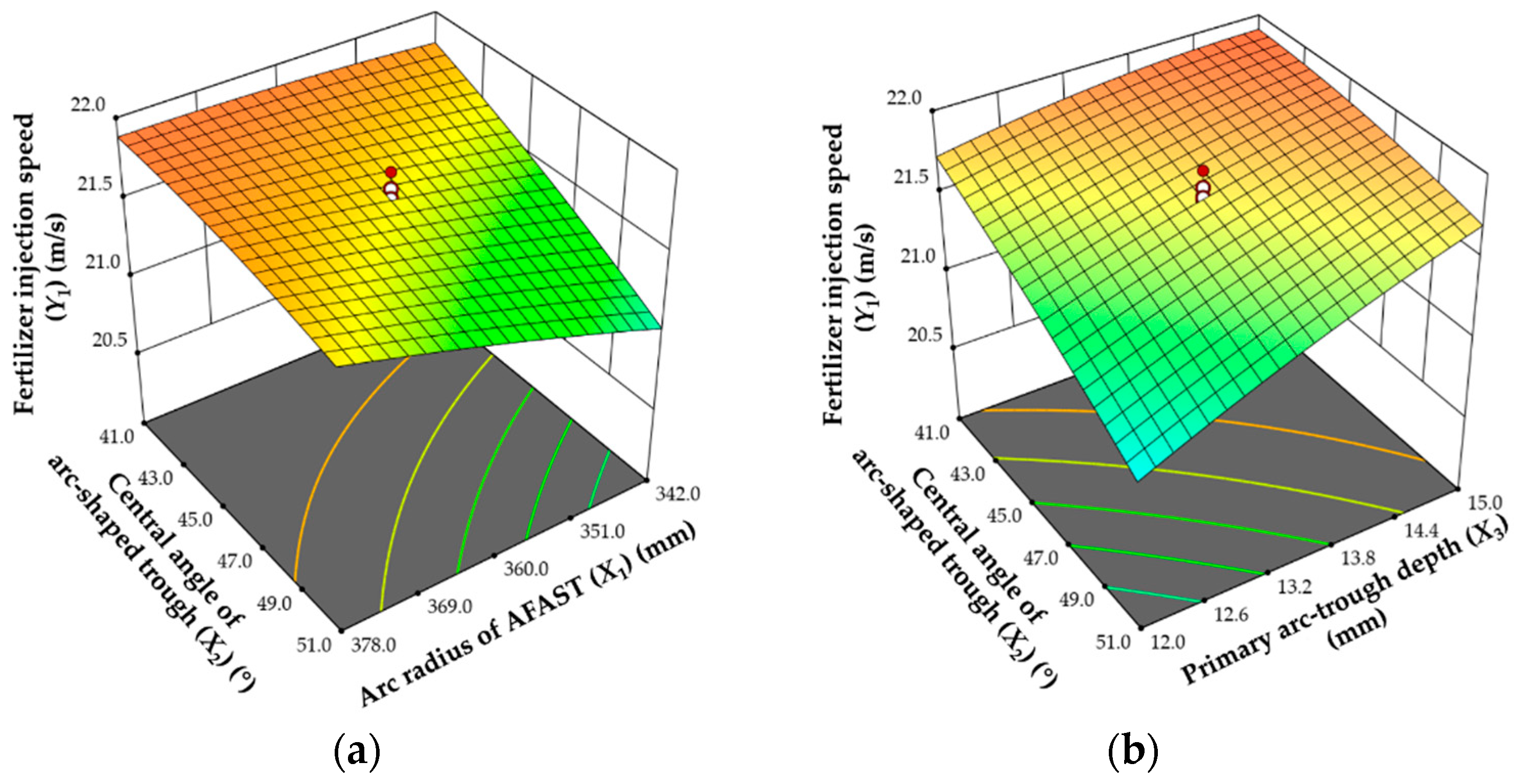
The effect of the factors on fertilizer injection speed is shown in Figure 5. It can be observed that the fertilizer injection speed is jointly affected by the arc radius of the AFAST, the central angle of the arc-shaped trough, and the primary arc-trough depth. When the trough depth is 13.5 mm and the central angle is fixed, injection speed increases with the arc radius. Conversely, when the arc radius is fixed, injection speed decreases with the increasing central angle because the enlarged outlet space weakens the airflow acceleration.
At an arc radius of 360 mm, the injection speed rises with the increase in trough depth but it will decrease with the increase in central angles. Based on the regression model, the optimal parameter combination is an arc radius of 377.84 mm, a central angle of 47.87°, and a trough depth of 14.88 mm. Under these conditions, the predicted injection speed is 21.98 m/s.

3.3.2. Effect of Factors on Fertilizer Separation Loss Rate and Parameter Optimization

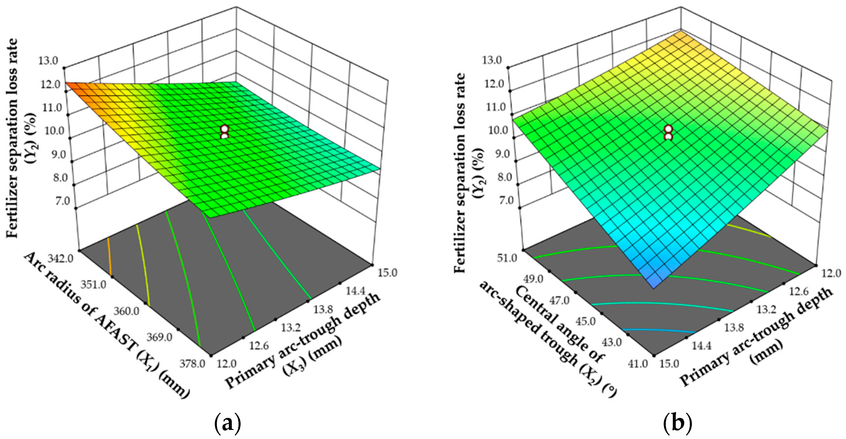
The influence of structural parameters on the fertilizer separation loss rate is presented in Figure 6. When the central angle is 46° and the trough depth is constant, the fertilizer separation loss rate will decrease with the increase in arc radius of the AFAST. Similarly, at a fixed arc radius of the AFAST, increasing the trough depth will reduce the loss rate, whereas at a fixed depth, the loss rate rises with the increase in central angle of the arc-shaped trough.
In summary, both larger arc radii and deeper troughs are favorable for reducing fertilizer separation loss, while greater central angles have the opposite effect. Regression model optimization identified the best combination as an arc radius of 377.84 mm, a central angle of 41.24°, and a trough depth of 15 mm, under which the predicted loss rate is 7.79%.

3.3.3. Effect of Factors on Outlet Airflow Speed and Parameter Optimization

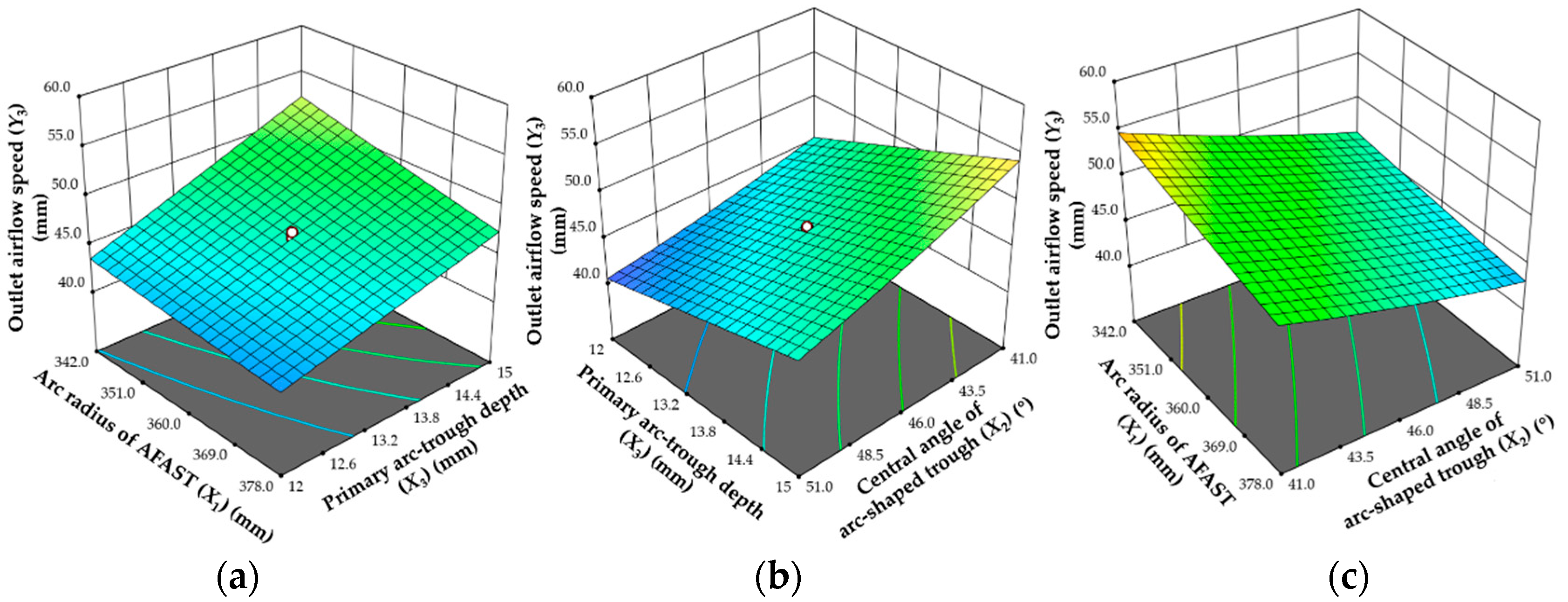
The effects of different parameters on the outlet airflow speed are shown in Figure 7. At arc radius of 360 mm, the airflow speed increases with the increase in trough depth but decreases with the increase in the central angle of the arc-shaped trough. When the arc-shaped trough depth is 13.5 mm, the airflow speed decreases with the increase in the arc radius of the AFAST and the central angle of arc-shaped trough.
These results indicate that the outlet airflow speed is particularly sensitive to the depth and the central angle of the arc-shaped trough. According to the regression model, the optimal configuration is an arc radius of 377.84 mm, a central angle of 50.76°, and a trough depth of 11.97 mm; then, the predicted airflow speed is 40.32 m/s.

3.4. Comprehensive Parameter Optimization and Experimental Verification

Design-Expert 13 was used for parameter optimization. According to the importance of the indicators, the target for the fertilizer injection speed is set as maximal, with a weight of 0.2; the target for fertilizer separation loss rate is set as minimal, with a weight of 0.3; and the target of outlet airflow speed is set as minimal and the weight is set as 0.5.
The optimal structural parameters for the air–fertilizer separator are obtained as follows: the arc radius of the AFAST is 377.84 mm, the central angle of arc-shaped trough is 44.77°, and the primary arc-trough depth is 12.47 mm. Then, the model predicts a fertilizer injection speed of 21.70 m/s, a fertilizer separation loss rate of 10.35%, and an outlet airflow speed of 43.28 m/s.
To verify the optimal parameter combination, verification tests were repeated three times using the constructed test system. The optimized parameters are rounded with the arc radius of the AFAST of 380 mm, the central angle of the arc-shaped trough of 45°, and a primary arc-trough depth of 12.5 mm.
The images of the fertilizer particles in the separator are captured using a high-speed camera, as shown in Figure 8. It can be observed that the fertilizer moves along the back wall of the arc-shaped separator and finally shoots into the soil.
The verification results showed that the mean values were 21.45 m/s for the fertilizer injection speed, 42.54 m/s for the outlet airflow speed, and 10.22% for the fertilizer separation loss rate; the test values of each factor are close to the predicted values, with errors of 1.2%, 1.7%, and 1.3%, respectively, indicating that the binomial optimization based on orthogonal rotation combination experiments and the predictions of the regression model have high accuracy and reproducibility.

4. Conclusions and Discussion

(1)
An air–fertilizer separator for a pneumatic deep fertilization machine was designed to separate the air and fertilizer before they enter the paddy soil and to direct the airflow away from the fertilizer. The structural parameters of the air–fertilizer separator were determined.
(2)
The testing system was developed, and the bench tests were carried out, and a regression model was established between the fertilizer injection speed, fertilizer separation loss rate, and outlet airflow speed, and the arc radius of the AFAST, central angle of arc-shaped trough, and primary arc-trough depth. Each factor and their interactions had a significant impact on the evaluation index. The regression models have a good fit and can be used for evaluation index prediction.
(3)
The optimal parameters of the air–fertilizer separator are determined using multi-objective optimization as follows: arc radius of the AFAST of 380 mm, central angle of the arc-shaped trough of 45°, and depth of the primary arc-shaped trough of 12.5 mm. Three verification tests were repeated using the built test system, and the results are a fertilizer injection speed of 21.45 m/s, a fertilizer separation loss rate of 10.22%, and an outlet airflow speed of 42.54 m/s. The air–fertilizer separator can meet the design requirements for deep pneumatic fertilization.
(4)
It should be noted that the present study was carried out mainly under controlled laboratory conditions. Field environments may affect the separation performance. In addition, only one type of fertilizer granule was tested. Therefore, a simulation study and field test should be carried out to verify the results of the study and optimize the parameters of the air–fertilizer separator.

Author Contributions

Conceptualization, M.X. and Y.S.; methodology, W.D.; software, B.C.; validation, M.X., D.C. and Y.S.; formal analysis, W.D.; investigation, M.Z.; resources, B.C.; data curation, Y.A.; writing—original draft preparation, W.D.; writing—review and editing, W.D.; visualization, Z.J. and Y.G.; supervision, M.X.; project administration, Y.S.; funding acquisition, M.X. All authors have read and agreed to the published version of the manuscript.

Funding

This research was funded by the National Natural Science Foundation of China (51975389).

Data Availability Statement

Data are contained within the article.

Acknowledgments

The authors are grateful to the reviewers and the editor for their valuable suggestions and assistance, and they express gratitude to the funders for providing financial support.

Conflicts of Interest

The authors declare no conflicts of interest.

References

  1. Chen, X.; Zhao, X.; Jiao, L.; Xing, Z.; Dong, D. Infrared microspectroscopy and machine learning: A novel approach to determine the origin and variety of individual rice grains. Agric. Commun. 2024, 2, 100038. [Google Scholar] [CrossRef]
  2. Kakar, K.; Xuan, T.D.; Noori, Z.; Aryan, S.; Gulab, G. Effects of Organic and Inorganic Fertilizer Application on Growth, Yield, and Grain Quality of Rice. Agriculture 2020, 10, 544. [Google Scholar] [CrossRef]
  3. Xie, Y.; Liu, H.; Shang, J.; Guo, L.; Zheng, G. Effect of Angle Between Center-Mounted Blades and Disc on Particle Trajectory Correction in Side-Throwing Centrifugal Spreaders. Agriculture 2025, 15, 1392. [Google Scholar] [CrossRef]
  4. Xin, M.J.; Jiang, Z.W.; Chen, T.Y.; Song, Y.Q.; Wang, Y.; Huang, W.Z. Design and experiment of the fertilizer centrifugal broadcaster with guiding chute for paddy field. Trans. Chin. Soc. Agric. Eng. 2023, 39, 67–75. [Google Scholar]
  5. Qi, X.Y.; Zhou, Z.Y.; Yang, C.; Luo, X.; Gu, X.; Zang, Y.; Liu, W. Design and experiment of key parts of pneumatic variable-rate fertilizer applicator for rice production. Trans. Chin. Soc. Agric. Eng. 2016, 32, 20–26. [Google Scholar]
  6. Tang, H.; Wang, J.W.; Xu, C.S.; Zhou, W.Q.; Wang, J.F.; Wang, X. Research progress analysis on key technology of chemical fertilizer reduction and efficiency increase. Trans. Chin. Soc. Agric. Mach. 2019, 50, 1–19. [Google Scholar]
  7. Ma, X.; Zhao, X.; Liu, S.S.; Wang, Y.W.; Wang, X.C.; Li, Z. Design and experiment of solid particle fertilizer variable rate fertilization device for high-speed rice transplanter. Trans. Chin. Soc. Agric. Mach. 2023, 54, 99–110. [Google Scholar]
  8. Wang, J.W.; Li, S.W.; Zhang, Z.; Li, Q.C. Design and experiment of electrical drive side deep hill-drop fertilization system for precision rice hill-direct-seeding machine. Trans. Chin. Soc. Agric. Eng. 2018, 34, 43–54. [Google Scholar]
  9. Chen, X.F.; Luo, X.W.; Wang, Z.M.; Zhang, M.H.; Hu, L.; Zeng, S.; Mo, Z.W. Experiment of synchronous side deep fertilizing technique with rice hill-drop drilling. Trans. Chin. Soc. Agric. Eng. 2014, 30, 1–7. [Google Scholar]
  10. Zeng, S.; Tang, H.T.; Luo, X.W.; Ma, G.H.; Wang, Z.M.; Zang, Y.; Zhang, M.H. Design and experiment of precision rice hill-drop drilling machine for dry land with synchronous fertilizing. Trans. Chin. Soc. Agric. Eng. 2012, 28, 12–19. [Google Scholar]
  11. Li, Z.Y. Side Deep Fertilizer Applicator. Chinese Patent CN91209468, 24 June 1992. [Google Scholar]
  12. Chen, M.; Chen, W.C.; Lin, R.X.; Liu, Z.Z.; Fang, H. An approach to the mechanisms of dibble deep urea applicator for paddy field. Trans. Chin. Soc. Agric. Mach. 1991, 22, 32–37. [Google Scholar]
  13. Wang, J.F.; Cao, G.B.; Yan, D.W.; Wang, J.W.; Weng, W.X.; Chen, B. Design and experiment of electric control double row deep fertilizing weeder in paddy field. Trans. Chin. Soc. Agric. Mach. 2018, 49, 46–57. [Google Scholar]
  14. Sikder, R.; Xiaoying, J. Urea super granule (USG) as key conductor in agricultural productivity development in Bangladesh. Dev. Ctries. Stud. 2014, 4, 132–139. [Google Scholar]
  15. Chatterjee, D.; Mohanty, S.; Guru, P.K.; Swain, C.K.; Tripathi, R.; Shahid, M.; Kumar, U.; Kumar, A.; Bhattacharyya, P.; Gautam, P.; et al. Comparative assessment of urea briquette applicators on greenhouse gas emission, nitrogen loss and soil enzymatic activities in tropical lowland rice. Agric. Ecosyst. Environ. 2018, 252, 178–190. [Google Scholar] [CrossRef]
  16. Wohab, M.A.; Islam, M.S.; Hoque, M.A.; Hossain, M.A.; Ahmed, S. Design and development of a urea super granule applicator for puddle rice field. J. Agric. Eng. Technol. 2009, 37, 57–62. [Google Scholar]
  17. Ahamed, M.S.; Ziauddin, A.T.M.; Sarker, R.I. Design of improved urea super granule applicator. Int. J. Appl. Sci. Eng. Res. 2014, 3, 98–104. [Google Scholar]
  18. Ahmed, M.R.; Billah, M.M.; Ziauddin, A.T.M. Battery operated USG applicator. Prog. Agric. 2012, 23, 75–80. [Google Scholar] [CrossRef]
  19. Hoque, M.A.; Wohab, M.A.; Hossain, M.A.; Saha, K.K.; Hassan, M.S.H.J. Improvement and evaluation of BARIUSG applicator. Agric. Eng. Int. CIGR J. 2013, 15, 87–94. [Google Scholar]
  20. Hossen, M.A.; Huda, M.D.; Islam, M.S.; Bhuiyan, M.G.K.; Rahman, M.; Nath, B.C. Design and development of a manually operated urea super granule (USG) applicator. Agric. Mech. Asia Afr. Lat. Am. 2013, 44, 85–91. [Google Scholar]
  21. Wohab, M.A.; Gaihre, Y.K.; Ziauddin, A.T.M.; Hoque, M.A. Design, development and field evaluation of manual-operated applicators for deep placement of fertilizer in puddled rice fields. Agric. Res. 2017, 6, 259–266. [Google Scholar] [CrossRef]
  22. Zhao, J.; Huang, Y.; Chen, C.Q.; Weng, X.X.; Zhu, J.X.; Bai, Z.F.; Xia, Q.W.; Wang, K.J. Side deep fertilization technology and device for rice. Agric. Eng. 2022, 12, 23–26. [Google Scholar]
  23. Zuo, X.J.; Wu, G.W.; Fu, W.Q.; Li, L.W.; Wei, X.L.; Zhao, C.J. Design and experiment on air-blast rice side deep precision fertilization device. Trans. Chin. Soc. Agric. Eng. 2016, 32, 14–21. [Google Scholar]
  24. Li, L.W.; Meng, Z.J.; Wang, X.O.; An, X.F.; Wang, P.; Wu, G.W. Simulation analysis of gas-solid two phase flow in pneumatic conveying fertilizer feeder of rice fertilizer applicator. Trans. Chin. Soc. Agric. Mach. 2018, 49, 171–180. [Google Scholar]
  25. Wu, C.; Fang, W.; Zhang, D. Process parameters optimization of Nymphaea’s hydraulic-gathering. Trans. Chin. Soc. Agric. Eng. 2012, 28, 288–292. [Google Scholar]
  26. Xin, M.J.; Jiang, Z.W.; Song, Y.Q.; Kong, A.; Chi, B.; Shan, R. Compression strength and critical impact speed of typical fertilizer particles. Agriculture 2023, 13, 2285. [Google Scholar] [CrossRef]
  27. Wang, T.Z. The confirming of the argument on airflow transportation mechanism. J. Chin. Agric. Mech. 2008, 4, 74–78. [Google Scholar]
  28. Fei, H.; Xu, S.; Tang, Z. Investigation on impact responses for rock-like brittle materials. Chin. J. Rock Mech. Eng. 2007, S1, 3416–3420. [Google Scholar]
  29. Johnson, K.L. Contact Mechanics; Higher Education Press: Beijing, China, 1992. [Google Scholar]
  30. Ye, Y.; Zeng, Y.W.; Zeng, C.; Jin, L. Experimental study on the normal restitution coefficient of granite spheres. Chin. J. Rock Mech. Eng. 2017, 36, 633–643. [Google Scholar]
  31. Tan, L.; Ji, A.M.; Huang, J.C. Parameter optimization of industrial hemp conveying mechanism based on ADAMS. J. Chin. Agric. Mech. 2023, 44, 42–47. [Google Scholar]
  32. Gao, G.B. Design and Experiment of Key Parts of Side-Depth Fertilizer Device with Pneumatic Conveying for Paddy. Master’s Thesis, Northeast Agricultural University, Harbin, China, 2019. [Google Scholar]
  33. Xu, L.Z.; Li, Y.M. Critical speed of impact damage on a rice kernel. Trans. Chin. Soc. Agric. Mach. 2009, 40, 54–57. [Google Scholar]
  34. Wang, Y. Dynamic Analysis and Experimental Study on Entry of Fertilizer Particles into Paddy Field with Pneumatic Topdressing and Deep Application. Master’s Thesis, Shenyang Agricultural University, Shenyang, China, 2023. [Google Scholar]
  35. Kong, L. Two-Phase Fluid Mechanics; Higher Education Press: Beijing, China, 2004. [Google Scholar]
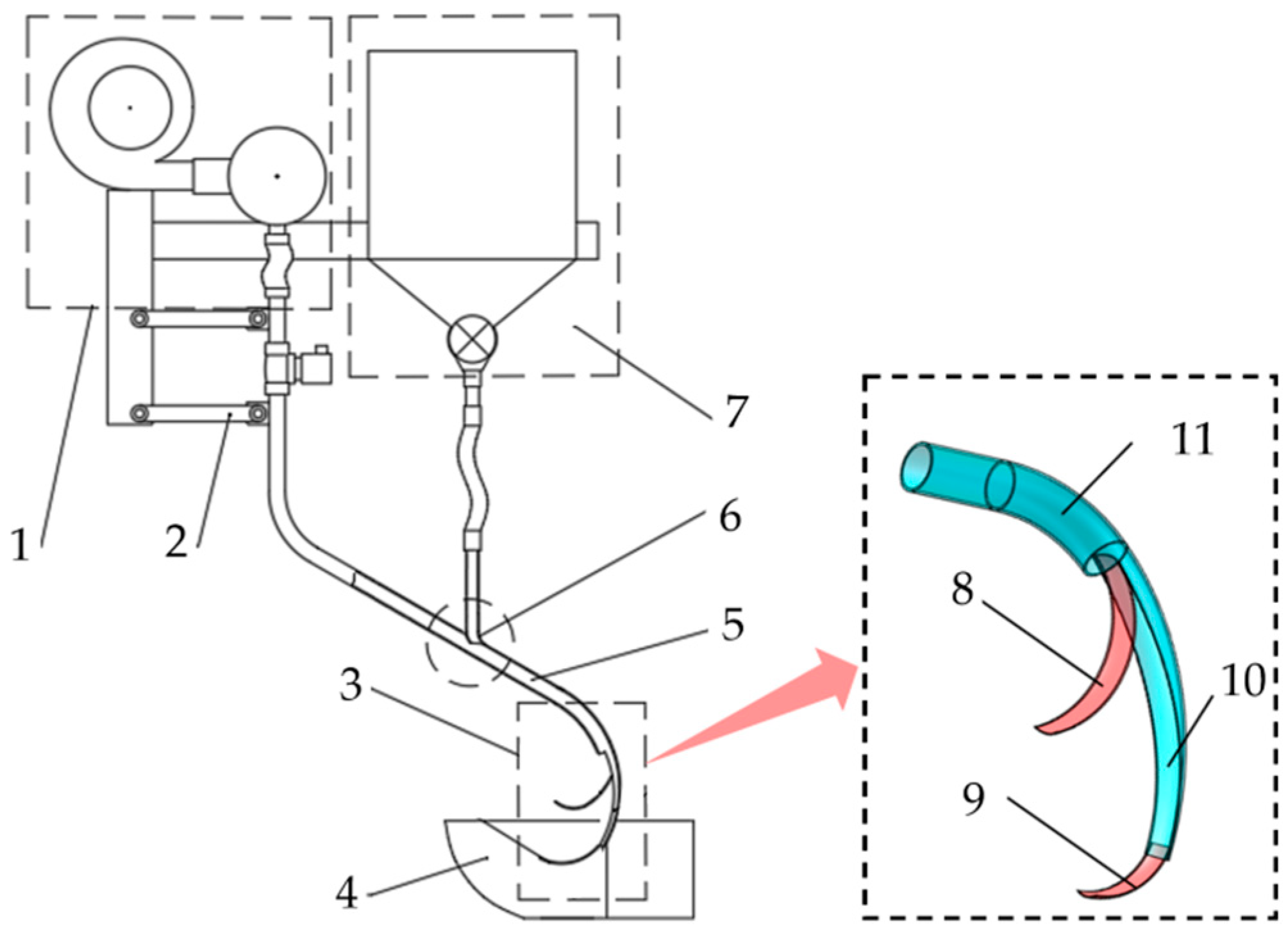
Figure 1. Overall structure of the pneumatic deep fertilization device for paddy fields. 1. Air supply system; 2. profiling mechanism; 3. air–fertilizer separator; 4. water divider; 5. fertilizer acceleration tube; 6. air–fertilizer mixing interface; 7. fertilizer metering system; 8. primary air-diverting arc plate; 9. secondary air-diverting arc plate; 10. arc-shaped trough; 11. air–fertilizer separation arc-shaped tube (AFAST).
Agriculture 15 01991 g001
Figure 2. Structural parameter of air–fertilizer separator. φi is the setting angle of the separator; ω is the center angle of the separator; α0 is the central angle of the arc-shaped trough; φr is the angle between the trajectory of the fertilizer entering the soil and the soil surface; OF is the bisector of the trough; AB is the primary air–fertilizer outlet; CD is the secondary air–fertilizer outlet; α1 is central angle of the primary air-diverting arc plate; α2 is the center angle of the secondary air-diverting arc plate; lm is the depth of EF; l2 is the depth of CD; r1 is the radius of the primary air-diverting arc plate; r2 is the radius of the secondary air-diverting arc plate.
Agriculture 15 01991 g002
Figure 3. The motion of the fertilizer particle entering into the arc-shaped air–fertilizer separation tube. R0 is the radius of the back wall of AFAST; Rm is the arc radius of AFAST center line; l0 is the distance between the initial incident position of the fertilizer particles and the back wall of AFAST, m; Op is the center of the fertilizer particle; O is the center of the separator; γi is the angle between the direction of the incident speed of the fertilizer particles and OOp; vi is the incident speed of the fertilizer particles; vr is the rebound velocity of the fertilizer particles; vrr is the radial rebound velocity of the fertilizer particles; vrt is the tangential rebound velocity of the fertilizer particles.
Agriculture 15 01991 g003
Figure 4. Air–fertilizer separator performance test bench. 1. Fan; 2. fertilizer feeder; 3. acceleration tube; 4. separation tube; 5. high-speed dynamic image analyzer; 6. arc-shaped trough; 7. AFAST; 8. primary air-diverting arc plate; 9. secondary air-diverting arc plate.
Agriculture 15 01991 g004
Figure 5. Effects of factors on fertilizer injection speed. (a) The interaction between the arc of AFAST and the central angle of the arc-shaped trough; (b) the interaction between the primary arc-trough depth and central angle of arc-shaped trough.
Agriculture 15 01991 g005
Figure 6. Effects of various factors on fertilizer separation loss rate. (a) The interaction between the primary arc-trough depth and arc radius of arc-shaped tube; (b) the interaction between the primary arc-trough depth and central angle of arc-shaped trough.
Agriculture 15 01991 g006
Figure 7. Influence of various factors on outlet airflow speed. (a) The interaction between the primary arc-trough depth and arc radius of arc-shaped tube; (b) the interaction between the primary arc-trough depth and central angle of arc-shaped trough; (c) the interaction between the arc radius of AFAST and the central angle of the arc-shaped trough.
Agriculture 15 01991 g007
Figure 8. Movement state of fertilizer inside the separator.
Agriculture 15 01991 g008
Table 1. Property parameters of materials.
MaterialDensity
(kg/m−3)
Poisson’s RatioElastic Modulus
(MPa)
Urea13320.25140
PMMA12000.411.95 × 105
Table 2. Factor-level code table.
LevelArc Radius of AFAST
X1 (mm)
Central Angle of Arc-Shaped Trough
X2 (°)
Primary Arc-Trough Depth
X3 (mm)
+1.683905416
13785115
03604613.5
−13424112
−1.683303811
Table 3. Experimental design and results.
No.Arc Radius of AFAST
X1 (mm)
Central Angle of Arc-Shaped Trough
X2 (°)
Primary Arc-Trough Depth
X3 (mm)
Fertilizer Injection Speed
Y1 (m/s)
Fertilizer Separation Loss Rate
Y2 (%)
Outlet Airflow Speed
Y3 (m/s)
1−1−1−1 21.5711.8446.55
21−1−121.8810.3644.31
3−11−1 20.5812.8541.29
411−121.2111.1240.06
5−1−1121.898.4757.83
61−1121.867.6550.98
7−11121.2310.7848.02
811121.9911.0244.73
9−1.680021.4111.649.1
101.680021.879.9343.59
110−1.68021.938.6352.94
1201.68021.2312.1741.39
1300−1.6821.1312.4540.32
14001.6822.008.8852.15
1500021.8310.3745.98
1600021.6710.346.65
1700021.5510.4346.23
1800021.5610.2145.97
1900021.6610.7845.93
2000021.739.845.93
2100021.6110.7846.13
2200021.6710.346.27
2300021.6410.4546.88
Table 4. Analysis of variance of regression equation of fertilizer injection speed.
SourceFertilizer Injection Speed, Y1/(m/s)
Sum of SquaresdfMean SquareF-Valuep-Value
Model2.4090.2725.21<0.0001 **
X10.4410.4441.34<0.0001 **
X20.8310.8378.5<0.0001 **
X30.7510.7570.60<0.0001 **
X1X20.1510.1514.560.0021 **
X1X30.0110.010.520.4831
X2X30.1610.1615.090.0019 **
X120.0110.010.590.4576
X220.02710.032.520.1363
X320.03410.033.220.0962
Residual0.14130.01--
Lack of fit0.07950.022.130.1632
Pure error0.059680.01--
Cor total2.54722---
SourceFertilizer Separation Loss Rate, Y2/(%)
Sum of SquaresdfMean SquareF-Valuep-Value
Model34.3893.8248.98<0.0001 **
X13.1913.1940.88<0.0001 **
X213.16113.16168.66<0.0001 **
X314.88114.88190.75<0.0001 **
X1X20.0810.081.050.3239
X1X30.8610.8611.090.0054 **
X2X31.9111.9124.50.0003 **
X120.2010.22.590.1315
X220.00210.00420.050.8198
X320.0110.09521.220.2893
Residual1.01130.078--
Lack of fit0.3150.0620.70.64
Pure error0.7180.09--
Cor total35.3922---
SourceOutlet Airflow Speed, Y3/(m/s)
Sum of SquaresdfMean SquareF-Valuep-Value
Model379.8942.2267.23<0.0001 **
X138.32138.32242.67<0.0001 **
X2148.241148.24938.73<0.0001 **
X3177.581177.581124.48<0.0001 **
X1X22.6112.6116.530.0013 **
X1X35.5615.5635.22<0.0001 **
X2X35.3615.3633.96<0.0001 **
X120.0810.080.480.5011
X222.0512.0512.960.0032 **
X320.0110.0140.090.7675
Residual2.05130.16--
Lack of fit1.1350.231.970.1875
Pure error0.9280.11--
Cor total381.8622---
Note: ** is extremely significant.
Disclaimer/Publisher’s Note: The statements, opinions and data contained in all publications are solely those of the individual author(s) and contributor(s) and not of MDPI and/or the editor(s). MDPI and/or the editor(s) disclaim responsibility for any injury to people or property resulting from any ideas, methods, instructions or products referred to in the content.