Article

Design and Experimental Validation of the Profiling Cutting Platform for Tea Harvesting

1
Institute of Agricultural Equipment, Zhejiang Academy of Agricultural Sciences, Hangzhou 310021, China
2
Key Laboratory of Agricultural Equipment for Hilly and Mountainous Areas in Southeastern China (Co-Constructed by Ministry and Province), Ministry of Agriculture and Rural Affairs, Hangzhou 310021, China
3
School of Biological and Chemical Engineering, Zhejiang University of Science and Technology, Hangzhou 310023, China
4
College of Optical, Mechanical and Electrical Engineering, Zhejiang A&F University, Hangzhou 311300, China
*
Author to whom correspondence should be addressed.
Agriculture 2025, 15(17), 1866; https://doi.org/10.3390/agriculture15171866
Submission received: 28 July 2025 / Revised: 27 August 2025 / Accepted: 29 August 2025 / Published: 31 August 2025
(This article belongs to the Section Agricultural Technology)

Abstract

The low quality of mechanized tea harvesting in China’s hilly plantations, often caused by irregular canopy morphology, necessitates improved technology. This study addresses this issue by proposing a contact-based profiling mechanism and a corresponding control method for tea cutting platforms. This cutting platform mainly consists of a canopy profiling mechanism, a tea harvesting unit, a lifting actuator, and a control system, containing a mathematical model correlating the tea canopy pose with sensor signals. Following a theoretical analysis of key components of the profiling device, we determined their structural parameters. Subsequently, a profiling control strategy was formulated, and an automatic control system for the profiling cutting platform was developed. Finally, a prototype was constructed and subjected to experimental validation to assess the dynamic characteristics of its pose adjustment and its profiling-based harvesting performance. The results of this experiment illustrate that after implementing the profiling system, the proportion of time the cutting blade remained in an optimal cutting position increased from 26.5% to 95.0%, an improvement of 68.5%, demonstrating that the system successfully achieves its design objective of the adaptive profiling apparatus in response to variation in canopy morphology. In addition, the integrity rate of harvested tea leaves increased from 50.7% without profiling to 74.6% with profiling, an improvement of 47.1%, which indicates the good performance of this profiling cutting platform. Therefore, this research provides a valuable reference for the design of intelligent tea harvesting machinery for the hilly tea plantations in China.

1. Introduction

China is a major tea-producing nation and one of the world’s leading producers, consumers, and exporters of tea, with a total output reaching 2.986 million tons, ranking first in the world [1,2,3]. Accordingly, tea cultivation is widely distributed across regions such as Jiangnan and Southwest, South, and North China. Serving as a primary economic pillar and a key export-oriented sector, the tea industry plays a crucial role in promoting agricultural structural adjustment, increasing the income of farmers, and expanding employment opportunities [4,5]. While Japan has achieved a high degree of automation in tea harvesting technology at a leading international level, its large-scale and ride-on machines are designed for Japan’s standardized tea gardens. In contrast, most of China’s tea plantations are situated in hilly areas characterized by steep slopes, non-standardized layout, uneven furrows, variable row spacing, and irregular canopy morphology. Consequently, foreign harvesting models perform poorly under these conditions [6,7], particularly in hilly tea plantations where the leaf damage rate during tea harvesting exceeds 40%. Therefore, there is an urgent need to enhance the independent research and development capabilities for tea harvesting technology and equipment tailored to the unique topographical and agronomical requirements of hilly tea plantations in China.
Currently, Japanese ride-on tea harvesters are not equipped with automatic canopy profiling systems for cutting platforms [8,9]. This is largely due to the standardized tea gardens, which are relatively flat, and their less stringent requirement for bulk tea harvesting, which ignores the need for complex profiling systems. However, numerous researchers have conducted studies on developing automatic profiling technologies to improve the precision of tea harvesting both in China and abroad [10,11]. For instance, Tang et al. [12] from Zhejiang University of Technology have developed a system using machine vision for adaptive cutter profiling, establishing a key method for a 3D rapid-drive tea harvester. By segmenting and identifying tender shoots, this system precisely controls the cutting height on the tea canopy based on the proportion and average height of these shoots, achieving 89% recognition accuracy for buds and young leaves under clear weather conditions. Nevertheless, under suboptimal photometric conditions, including high-intensity solar radiation (midday) or overcast environments, performance degradation manifests as reduced accuracy ranging between 62% and 68%, coupled with increased cutting height deviation expanding from ±3–5 mm to ±8–12 mm. Similarly, Dong et al. [13] have proposed an automatic profiling method for the cutter, which uses ultrasonic sensors to perceive the distance between the reciprocating cutter and the tea canopy. They have used Hampel and low pass filtering algorithms to pre-process the distance information online, eliminating the influence of leaf gaps and cutter vibrations on the estimation of the true canopy height, thus achieving accurate detection of the canopy position. However, the post-filtering ultrasonic measurements still show deviations of ±5–8 mm from equipment vibrations and canopy voids, causing over 18% cutter misalignment. Chen et al. [14] from Zhejiang Sci-Tech University also have utilized the synergistic action of LiDAR and the harvesting mechanism. By employing LiDAR sensors to fit the tea canopy curve, they accurately matched the cutting tool to the canopy surface for automatic profiling harvesting of the top shoots and subsequently developed a ride-on profiling tea harvester prototype with distributed control. Nevertheless, in areas with dense branching and overlapping leaves, the canopy curve fitting accuracy decreases to ±6–9 mm, resulting in the cutter maintaining optimal positioning for only 58–65% of operation time. To conclude, these profiling technologies primarily rely on non-contact methods such as machine vision-based image processing, ultrasonic ranging, or LiDAR curve fitting to identify the shoot position and control the attitude of cutting platforms. Nevertheless, these non-contact identification methods are susceptible to environmental factors like varying light conditions and color overlap between tender shoots and the background, which is highly prone to a reduction in the accuracy in tender shoot recognition. Noticeably, Yan et al. [15] from Anhui Agricultural University have established a system that uses changes in the angle of a baffle plate contacting the canopy height in real-time, therefore controlling the ascent and descent of the cutter via an angle sensor and a PLC. While this approach offers a viable direction for bulk tea profiling, its accuracy can be compromised by variations in contact force, resulting in data instability and affecting harvest quality.
To overcome these limitations, this study proposes a novel contact-based tea canopy profiling mechanism and a corresponding closed-loop control method by establishing a mathematical model that links canopy pose to sensor signals, developing an automatic pose adjustment system for the cutting platform, and constructing the design and implementation of its software and hardware. Finally, this study aims to verify the dynamic performance and harvesting effectiveness of the system, offering a feasible solution for intelligent tea harvesting in a challenging hilly environment.

2. Materials and Methods

2.1. Overall Design of the Profiling Cutting Platform

2.1.1. Overall Structure of the Profiling Cutting Platform

The overall structure of the adaptive profiling cutting platform, as illustrated in Figure 1, is composed of a canopy profiling mechanism, a tea harvesting unit, a lifting actuator for the platform, and a control system. As for the profiling mechanism, it consists of three profiling plates, angle sensors, and torsion springs whose arrangement corresponds to the shape of the cutter blade. The tea harvesting unit is a Kawasaki SV100 (Zhejiang Kawasaki Tea Machinery Co., Ltd., Hangzhou, China) two-person portable tea harvester [16]. The header lifting mechanism includes motors and ball screw linear modules, with the harvesting unit connected beneath the header lifting actuator via a linkage system. During the harvesting operation, the canopy profiling mechanism detects the real-time pose of the tea canopy, converting this information into angular signals for the control system. Based on this canopy pose information, the control system then commands the lifting actuators to adjust the pose of the platform, achieving adaptive profiling harvesting of the canopy surface.

2.1.2. Control System Principle

The control system, depicted in Figure 2, mainly comprises a microprocessor module, an input model, an output module, and a host computer module for programming and data acquisition. The microprocessor module utilizes an ESP-WROOM-32 as the core control board, responsible for receiving and processing all input signals for the entire system. The input module consists of multiple angle sensors, a proximity switch, and associated circuitry. The angle sensors capture the rotational signals of the shafts to which the profiling plates are mounted, while the proximity switches detect the position of the cutter platform to provide a zero-reference point for the motors. In the input stage, the angle sensors transmit data via RS-485 to the microprocessor for computation. Subsequently, the resulting output is sent to the output module as a position control command via the Modbus protocol. The motor executes the corresponding actions as instructed, driving automatic control of the ball screw linear modules to raise or lower the platform, thus adjusting the pose of the cutter.

2.2. Design of Key Components of the Profiling Mechanism

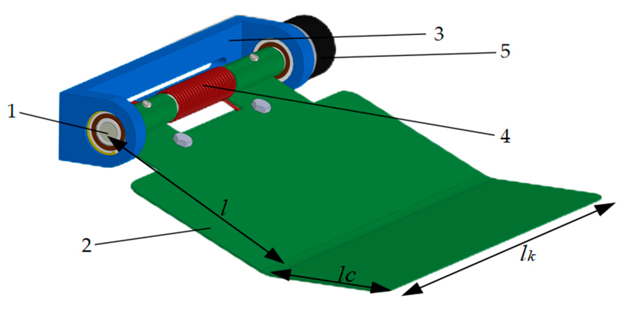
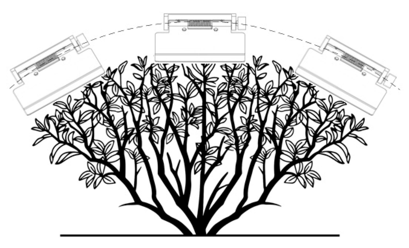
A contact-based canopy profiling device was designed, as shown in Figure 3. The device is primarily composed of profiling plates, torsion springs, and angle sensors. To overcome the possible inaccuracies of a single profiling plate in detecting the canopy pose, three profiling plates are arranged symmetrically (left, center, and right). During the profiling harvest, as depicted in Figure 4, the device’s profiling plates are in direct contact with the canopy. As the canopy height changes, the plates pivot up or down. Each plate is fixed to a mounting shaft connected to an angle sensor, which measures the rotational angle in real time. Then this information is used to adjust the position of the cutter based on relevant parameters, thus realizing the profiling harvesting of the tea leaves.

2.2.1. Design of the Tea Canopy Surface

As depicted in Figure 5, the geometric parameters of the profiling plate are determined based on the relationship between the swing angle of the profiling plate and the change in canopy height [17,18].
When the profiling mechanism moves from position 1 to position 2, the contact point between the profiling plate and the canopy shifts from P1 to P2, and the angle of the plate relative to the horizontal changes from β to γ. This change in canopy height, Δh, can be illustrated as
Δ h = H H = l ( sin β sin γ )
where Δh is the change in canopy height calculated by the angle in mm, l is the length of the profiling plate’s swing arm (mm), β is the initial angle between the plate’s swing arm and the horizontal plane (°), and γ is the real-time angle between the plate’s swing arm and the horizontal plane (°).
Consequently, the real-time angle γ of the plate’s swing arm relative to the horizontal plane is given by
γ = arcsin ( sin β Δ h l )
Based on preliminary field surveys of hilly tea gardens, the canopy height variation is typically in the range of 0–80 mm. Thus, considering the dimensions and installation requirements of the profiling plate, we set a target variation Δhmax = 60 mm. The swing arm length l is chosen as 140 mm, and the initial angle β is set to 25°. Thus, the real-time angle γ is in a deflection angle range of 15° to 46°, satisfying the design requirements. Furthermore, given a cutter width of 1000 mm, the width of each plate, lk, is chosen to be 250 mm, and the length of the side, lc, is set to 80 mm for uniform coverage.

2.2.2. Design of the Torsion Spring

The torsion spring is selected based on a force analysis of the profiling mechanism and the mechanical properties of tea shoots [19,20], ensuring that the pressure exerted by the plate maintains it within the required cutting depth. The force analysis is depicted in Figure 6, revealing that the primary forces acting on the profiling plate are the spring’s torsional force (F), the plate’s weight (G), and the supporting force from the tea shoots (F1).
The supporting force F1 is the reaction force generated by the contact between the profiling plate and numerous buds and leaves, whose magnitude primarily depends on the contact area and the compression depth. Therefore, F1 can be illustrated as
F 1 = ρ c × s × ( k 3 k 2 e k 1 x )
In this equation, ρc is the shoot density, in n/mm2; s is the contact area between the profiling plate and the canopy surface (mm2); k1, k2, and k3 are fitting coefficients for the supporting force obtained from compression tests on tender shoots [21]; and x is the compression depth of the buds and leaves (mm). According to prior statistical analysis of the physical parameters at the plucking position of tender tea shoots, x = 70 mm is selected for the calculation.
Considering that the profiling plate is constructed by joining two rectangular plates, the coordinates of its center of gravity, Point A (XA, YA), are given by
X A = x i · Δ A i A = x 1 A 1 + x 2 A 2 A 1 + A 2 Y A = y i · Δ A i A = y 1 A 1 + y 2 A 2 A 1 + A 2
In this formula, Point A (XA, YA) are the coordinates of the profiling plate’s center of gravity. A1 and A2 are the areas of the two respective rectangles (mm2). (x1, y1) and (x2, y2) are the coordinates of the centers of the two rectangles.
Furthermore, the force balance for the profiling plate is thus expressed as
M + G L O A cos θ 1 = F 1 L O B cos θ 2 + F f L O B sin θ 2
In this equation, M stands for the torque generated by the torsion spring (N·mm), G the gravity of the plate (N), and LOA the lever arm for the gravitational force (mm). θ1 and θ2 are the angles formed between the horizontal positive direction and the lines connecting the pivot point to the plate’s center gravity, Point A, and the canopy contact, Point B, respectively (°), and Ff represents the frictional force produced.
The calculation for selecting the torsion spring is shown as
M = F L = E d 4 α n 3660 n D
In this formula, F is the torsional force of the spring (N), L the length of the lever arm (mm), E is the material’s modulus of elasticity (MPa), αn is the torsion angle (°), n is the number of effective coils, D is the mean diameter of the spring (mm), and M is the torque applied by the torsion spring (N·mm).
Based on these calculations, a torsion spring with a wire diameter of 2.5 mm, a mean diameter of 15 mm, 6 active coils, and a lever arm of 33.5 mm is selected.

2.3. Software Design of the Profiling Cutting Platform Control System

2.3.1. Acquisition Profiling Control Strategy for the Header

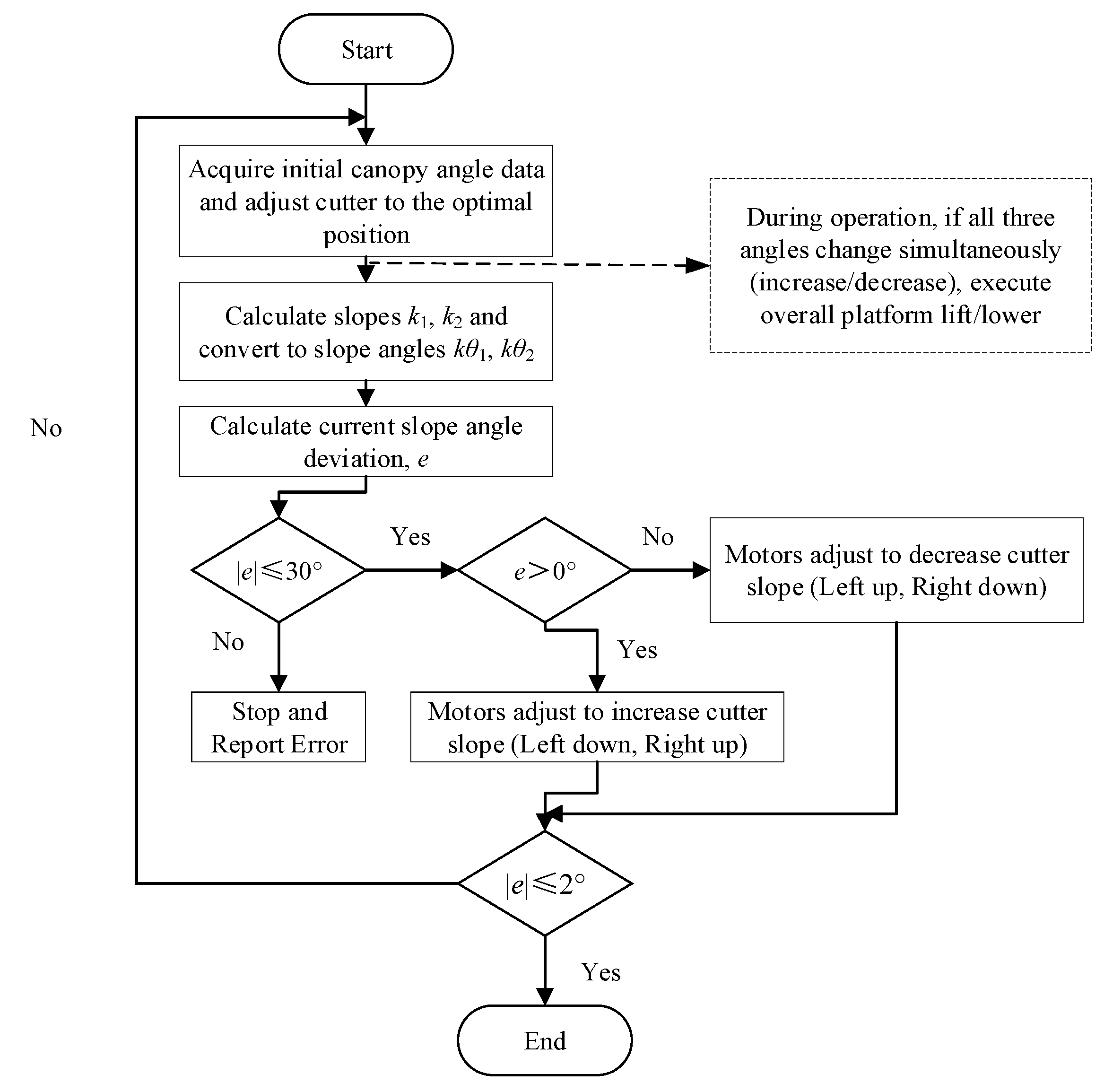
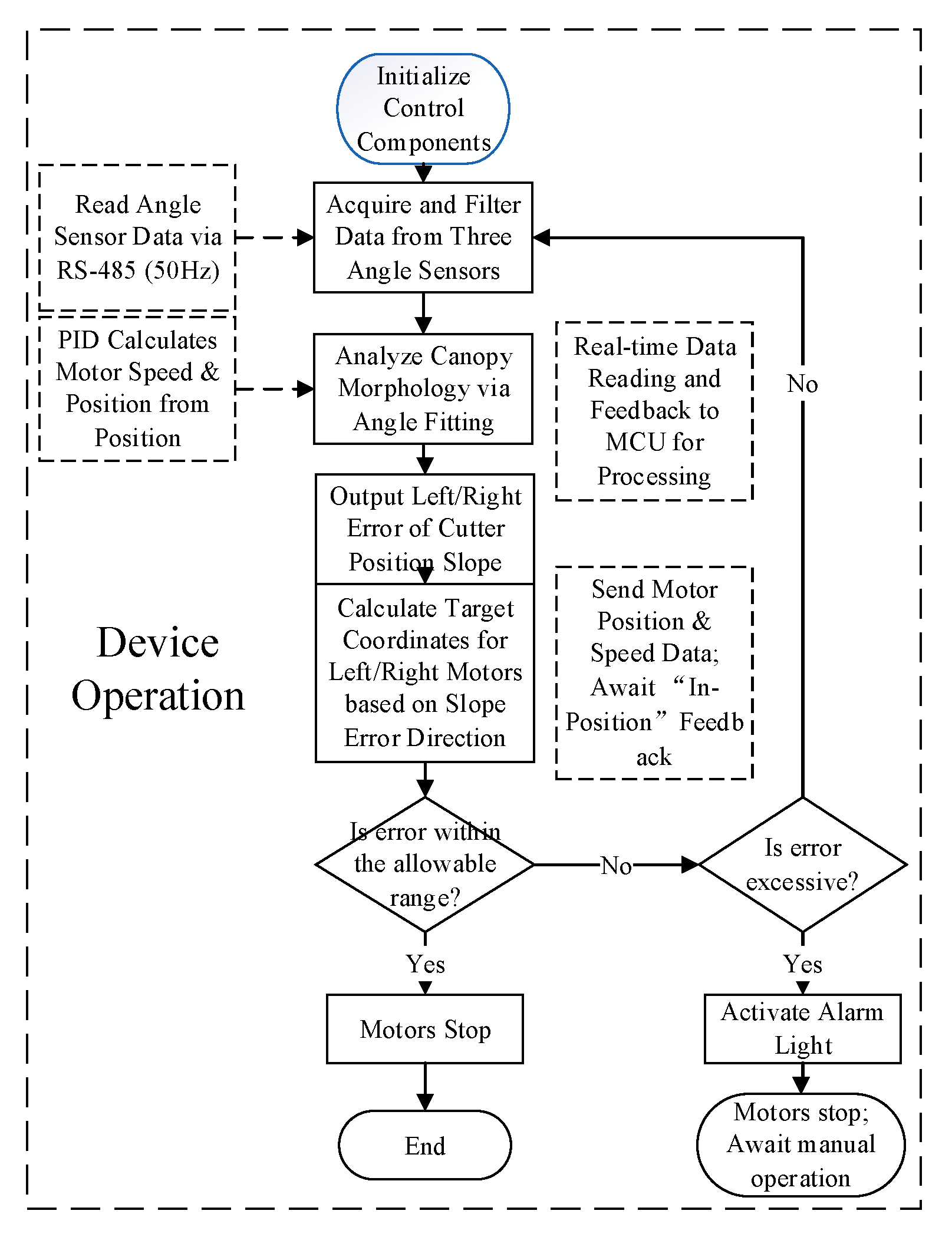
The control principle of the adaptive adjustment system is to regulate the pose of the cutter by comparing the actual slope of the header’s cutter blade with the canopy slope derived from the three profiling plates. In operation, the initial angles of the three profiling plates upon first contact with the canopy are captured as the initial morphological parameters. When it is then adjusted to an appropriate position, the cutter establishes this relative orientation as the present value for the ideal cutting position. Subsequently, the system calculates two slopes: the slope of the canopy pose (k1), derived from the three profiling plates, and the slope of the cutter blade (k2). Within their respective coordinate systems, these slopes can be converted into angles, 1 and 2. The difference between these two angles yields the deviation of the cutter’s current position from the optimal cutting position, denoted as e, e = 12. If e is within a predefined adjustment threshold, the controller does not send a command, and the header remains stationary. If e falls outside this threshold, the control action is triggered in two conditions. When e > 0, the motors on the left and right sides of the header adjust to increase the header’s slope. When e < 0, the motors act to decrease the header’s slope until e is back within the target criteria, at which point the motors cease operation. This control logic employs specific thresholds: if |e| ≤ 2°, no position adjustment is made; if the absolute deviation |e| > 30°, the system warns of an anomaly, halts operation, and prompts for manual inspection. The overall control strategy is illustrated in Figure 7.
Acquisition of Tea Canopy Pose Information
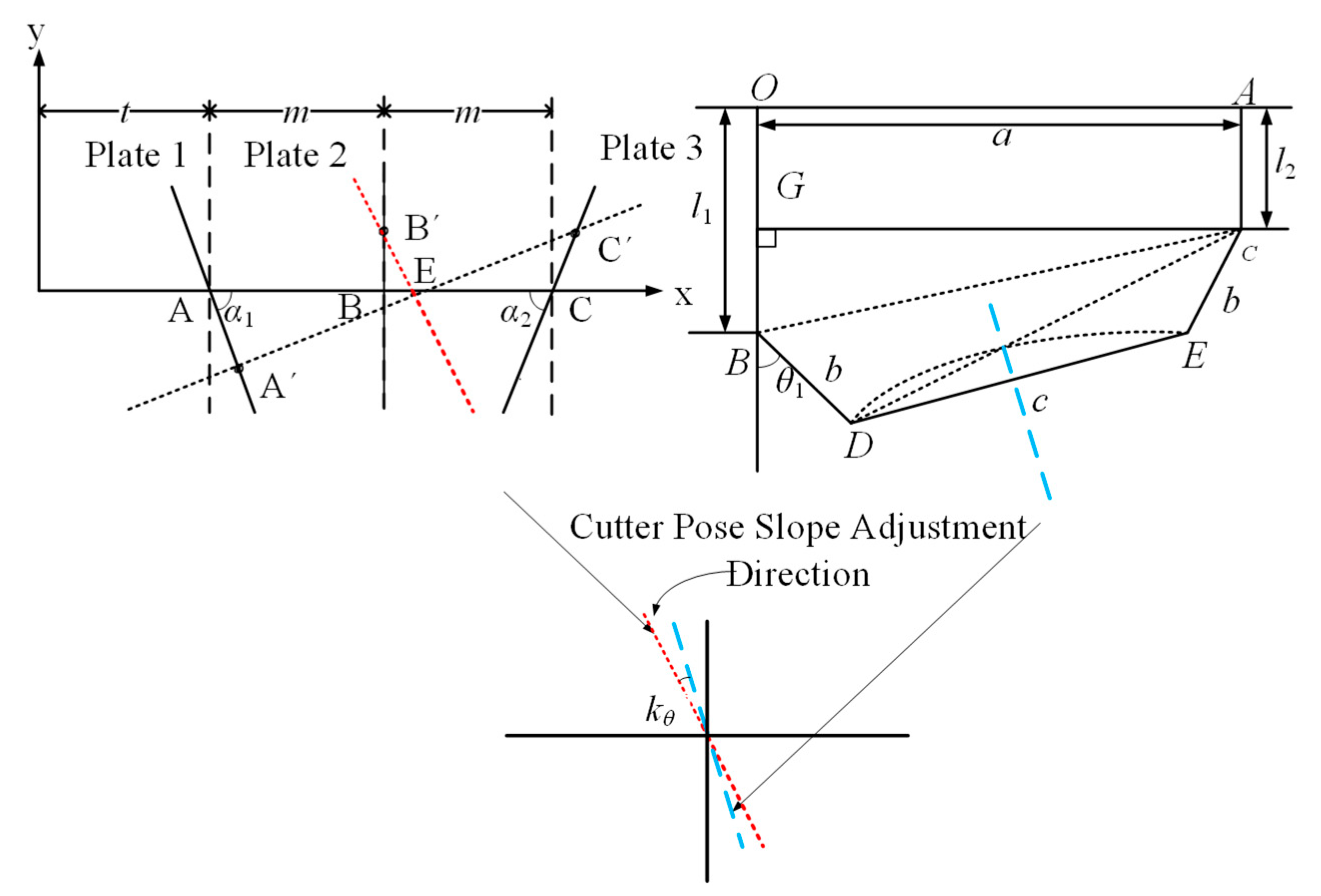
Figure 8 showcases the installation of the tea canopy profiling device. During operation, the profiling plates pivot up and down in response to changes in the canopy’s morphology. The vertical movement of the three plates can be conceptualized as projections onto three parallel lines distributed across the left, center, and right of the device. In this scenario, the horizontal distance from a side profiling plate to its corresponding lifting mechanism is denoted by t, and the lateral installation distance between adjacent profiling plates is m.
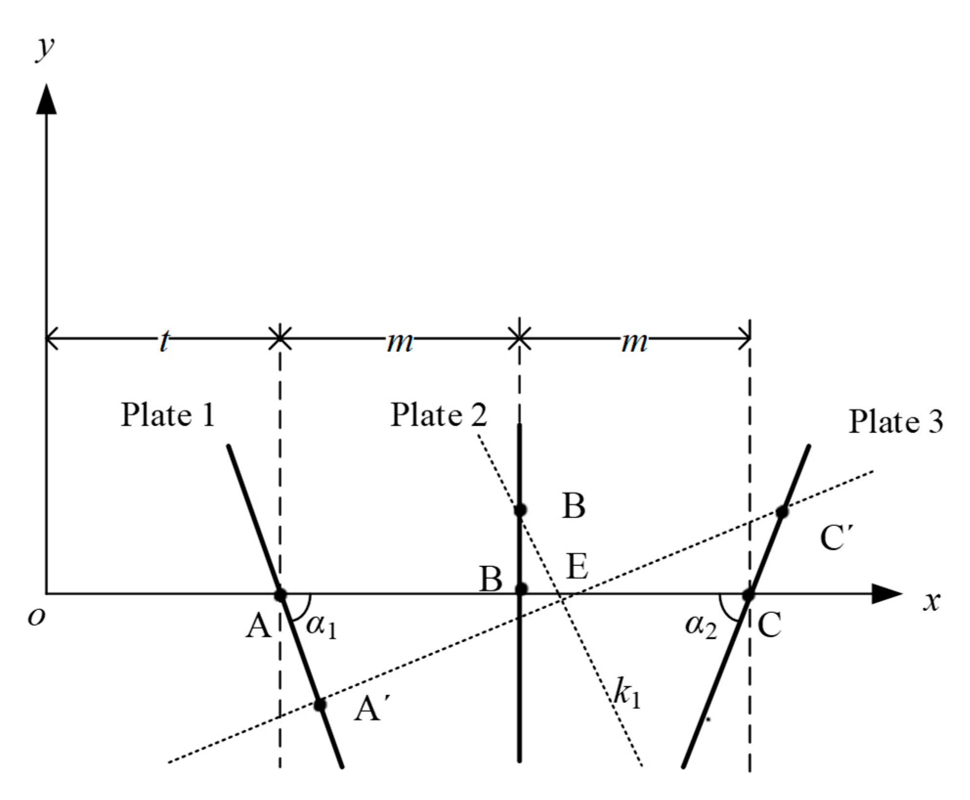
As shown in Figure 9, it can be assumed that the projection points of the three plates are initially at positions A, B, and C, and at a subsequent moment, they move to A′, B′, and C′. The lengths of the three profiling swing arms, lA, lB, and lC are equal to l. The vertical displacements along the three projection lines are denoted as lA, lB, and lC. In this diagram, α1 and α2 represent the setup angles of the plates at the initial state. In the initial condition, the angles of these three plates are β1, β2, and β3. After a change in the canopy surface, the angles become γ1, γ2, and γ3. Thus, based on the geometric relationship among the plate angles, swing arm length, and canopy undulation, the vertical displacements, lA, lB, and lC can be calculated, which in turn allows for the determination of the coordinates of the new projection points:
l A = l · sin β 1 sin γ 1 l B = l · sin β 2 sin γ 2 l C = l · sin β 3 sin γ 3
Then the coordinates for the projection points, A′, B′, and C′, along with E, can also be determined: t + l A cos α 1 , l A sin α 1 , m + t , l B , 2 m + t + l C cos α 2 , l C sin α 2 , 2 m + t + A cos α 1 + C cos α 2 2 , A sin α 1 + C sin α 2 2 .
Subsequently, from the coordinates of Points B′ and E, the slope K1 of the line B′E is calculated, representing the current pose information of the tea canopy:
K 1 = sin α 1 sin β 1 sin α 1 sin γ 1 + sin α 2 sin β 3 sin γ 3 cos α 1 sin β 1 sin sin γ 1 + sin β 3 sin sin γ 3 cos α 2
Acquisition of Header Pose Information
As depicted in Figure 10, the geometric relationship of the linkage determines the cutter’s slope. The angle θ1 is the tilt angle of the linkage frame and is measured by a sensor. The lengths AO (denoted as a), BD (b), CE (also b), and DE (c) are known, fixed geometric parameters of the device. The lengths l1 and l2 are acquired in real-time from the servo motors, determined based on the displacement of the slide compared with its original position. G represents a perpendicular line segment passing through point C, while H is a point on the extension of line AC.
According to the geometric relationships, the coordinates of points D and E can be determined through
b sin θ 1 , l 1 + b cos θ 2 , a b sin E C H , l 2 + b cos E C H
Then the slope of the cutter header K2 is
K 2 = b sin E C H + b sin θ 1 a l 2 + b cos E C H l 1 b cos θ 1
The ∠ECH in this equation is derived from geometric calculation, which is not derived in detail here.
Deviation Between Tea Canopy and Header Pose Information
To compare the inclination of the two slopes, the following steps are taken. The first step is to analyze the angle of each slope with the arctangent function. For slopes K1 and K2, the angles accordingly are arctan (K1) and arctan (K2). The next step is to convert angles to degrees. The calculated angles are typically in radians and must be converted to degrees following the formula: Angles (degrees) = Radians × 180/π. Finally, the angle magnitudes are compared. The two converted angle values, 1 and 2, are then compared to determine whether the first slope’s inclination is greater than, less than, or equal to the second’s counterpart. This method allows for a quantitative comparison of the two slopes. Noticeably, the inclination is relative as it depends on the choice of coordinate system and direction of rotation. Thus, a consistent reference frame must be applied in the comparison of the angles. The principle of pose adjustment is displayed in Figure 11.

2.3.2. Design of Control System Program

The main software program starts by initializing the angle sensors, servo motor controllers, and related components. In the adaptive mode, a subroutine for angle signal acquisition is functioning and collects the current angles of the three profiling plates relative to the canopy. This offers the canopy data parameters, enabling real-time monitoring of the slope difference between the profiling header and the undulating canopy morphology. Subsequently, the program computes and compares the slope of the cutter’s position with the slope of the canopy’s pose. Thus, the system adjusts based on the deviation and continues running until the slopes are nearly identical, with the achievement of the profiling effect.
The system features two modes of manual adjustment and automatic profiling. On the one hand, in manual mode, the motor on each side of the device can be controlled independently via an operation panel to change the header’s pose. On the other hand, the automatic profiling mode needs an initial setup where the three profiling plates and the cutter are set to a starting position, ensuring the “morphology” of the plates closely matches the pose of the cutter’s arc. Then the system uses the output signals from the angle sensors to calculate the relationship between the header’s current slope and the slope derived from the three plates. Based on the received data, it adjusts the height of the left and right ball screw platforms. Hence, the cyclical performance is obtained in this process of detection, calculation, and adjustment. Noticeably, this control method minimizes the number of adjustments and the time required for regulation, therefore ensuring the best effect in the shortest time. Furthermore, the reduced frequency of adjustments also decreases the operational cycles of the motors, thus extending the service life of the electrical components. In short, this approach effectively mitigates large inertial vibrations and jumps resulting from high-frequency adjustments, resulting in smooth and precise header movement at a low cost. The software control flowchart is presented in Figure 12.

3. Experimental Validation and Results

3.1. Experimental Verification with a Physical Prototype

Experimental Conditions

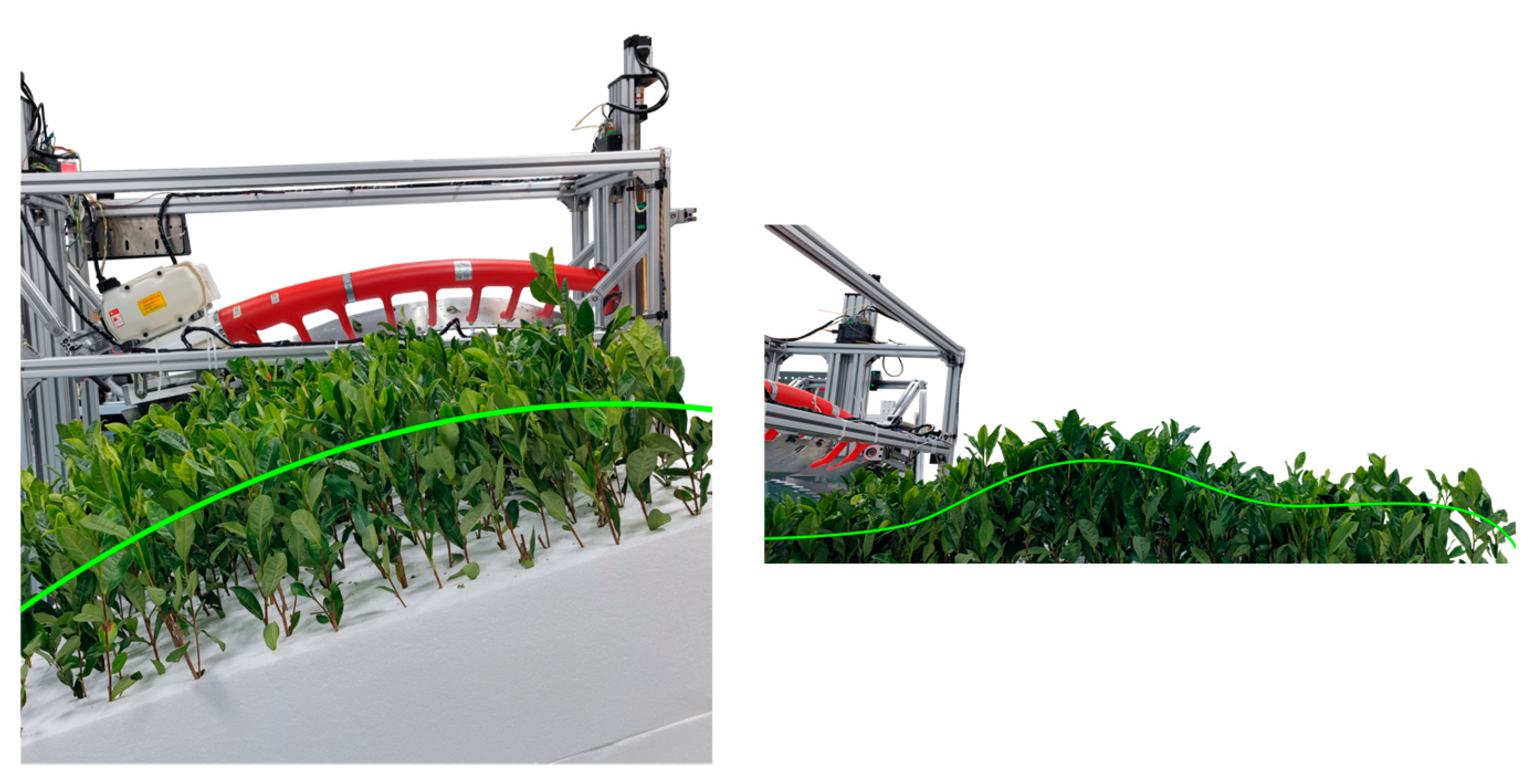
An experimental prototype of the tea profiling cutting platform was constructed to test the dynamic performance of the header’s pose control system and its harvesting effectiveness. The tests aimed to collect data on the response speed and precision of the header pose control system, and harvesting effectiveness, under the conditions of randomly changing canopy morphology. Specifically, the experiments were conducted in the laboratory of the Institute of Agricultural Equipment, Zhejiang Academy of Agricultural Sciences (Zhejiang Branch of the Chinese Academy of Agricultural Mechanization Sciences), as shown in Figure 13. In practice, the main experimental materials were a tea canopy model, a Kawasaki SV100 harvester (Zhejiang Kawasaki Tea Machinery Co., Ltd., Hangzhou, China), the canopy profiling device, foam boards, Miran WOA-A-I-R angle sensors (linearity precision ≤ 0.02%FS, Shenzhen Milang Technology Co., Ltd., Shenzhen, China), an ESP-WROOM32 microcontroller unit (MCU, LeXin Information Technology (Shanghai) Co., Ltd., Shanghai, China), and a host computer.

3.2. Experimental Method

3.2.1. Response Speed and Precision Tests of the Profiling Header Control System

In practical applications, the dynamic characteristics of the pose control system, particularly its response speed and precision, are vital for ensuring harvest quality, especially when encountering the highly variable and undulating canopy morphology. To evaluate the header’s control speed, vertical lifting of the canopy model was used to measure the motor’s speed response for header elevation. Two sets of tests were conducted where the tea canopy was raised vertically by 30 mm and 50 mm. Since the motors must overcome gravitational forces during ascent, the descent time is theoretically shorter and was therefore excluded from this analysis. Before the test, it was ensured that the profiling plates of the device were in contact with the canopy model and within their preset angular range. During this experiment, the vertical movement of the tea canopy was simulated by inserting and removing foam boards of various thicknesses to control the height of the canopy model. At the same time, the system operated and read the motor position signals and recorded the time taken for the header to adjust to the target height. Thus, the collected position data and time were used to evaluate the height control capability of the system through comparative analyses.
To assess the pose control precision of the header, the tea canopy was subjected to random vertical and tilting (left and right) movements to simulate the morphological changes that occur in actual field conditions. Thus, a systematic procedure was applied. Prior to the test, it was first ensured that the profiling plates were in continuous contact with the canopy model and operating within their preset angular range. The entire tea canopy model was then randomly raised, lowered, and tilted. During this process, the signal parameters were recorded and saved for subsequent calculation and conversion. Lastly, it was essential to check if the system’s regulation precision is within the expected range (|e| ≤ 2°) after comparing the changes in the canopy slope and the cutter blade slope.

3.2.2. Harvesting Performance Test of the Profiling Cutting Platform

Harvesting tests using the profiling cutting platform were conducted indoors on a custom-built tea canopy model, which can simulate variable canopy morphology. As shown in Figure 14, this model features a vertical undulation range of 6–8 cm and a tilt angle of 20°. Under these conditions, the tea canopy model was moved horizontally at a speed of approximately 0.5 m/s to simulate the actual harvesting process and to evaluate the effectiveness of the profiling harvesting. At the same time, a control group was set up using a harvesting test conducted without the profiling control. For each test, the tea canopy model moved 5 m, with a total of two harvesting tests for each group. Given the experimental constraints, the profiling effectiveness was mainly evaluated based on the post-harvest integrity rate of the tea leaves.

3.3. Experimental Results and Analysis

3.3.1. Response Speed Test of the Profiling Cutting Platform Control System

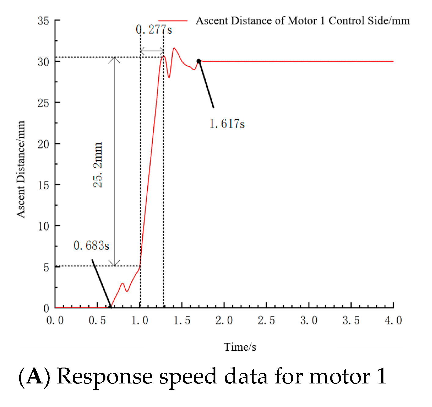
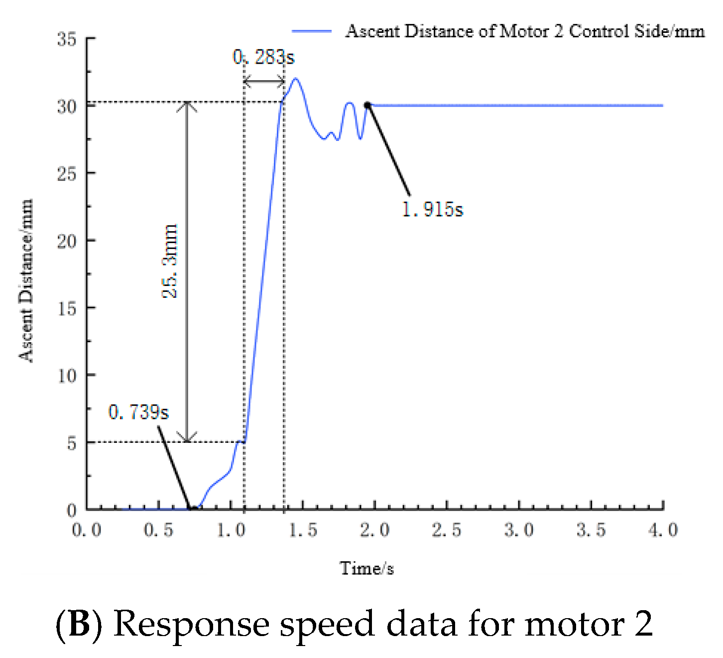
For this experiment, the adjustment process of the header was simulated in response to the entire canopy surface rising by 30 mm and 50 mm, a scenario encountered during harvesting. The data recorded from these tests are displayed in Figure 14 and Figure 15.
As evidenced by the Figure 14 and Figure 15 and Table 1, a rapid upward movement of the header was initiated upon activation of the profiling control system, which then stabilized upon reaching the designed height. In the 30 mm ascent test, the response speeds for the left and right headers were 90.97 mm/s and 89.40 mm/s, respectively, with a mean adjustment speed of 90.2 mm/s and a settling time of 1.05 s. In the subsequent 50 mm ascent test, the response speeds were 91.31 mm/s and 90.30 mm/s, resulting in a mean adjustment speed of 90.8 mm/s and an average stabilization time of 1.06 s. The motor control strategy employed conventional servo motor acceleration–deceleration control, with the observed 90 mm/s ascent response speed being lower than the no-load speed due to the motor overcoming implement weight and operational load during adjustment. This performance demonstrates the system’s practical adaptability while remaining consistent with the sub-1.5 s stabilization time reported in the literature [15]. Overall, this system demonstrates a short duration from the initiation of the adjustment to the achievement of stability, indicating a high performance that satisfies the operational requirements.

3.3.2. Response Accuracy Test of the Profiling Cutting Platform Control System

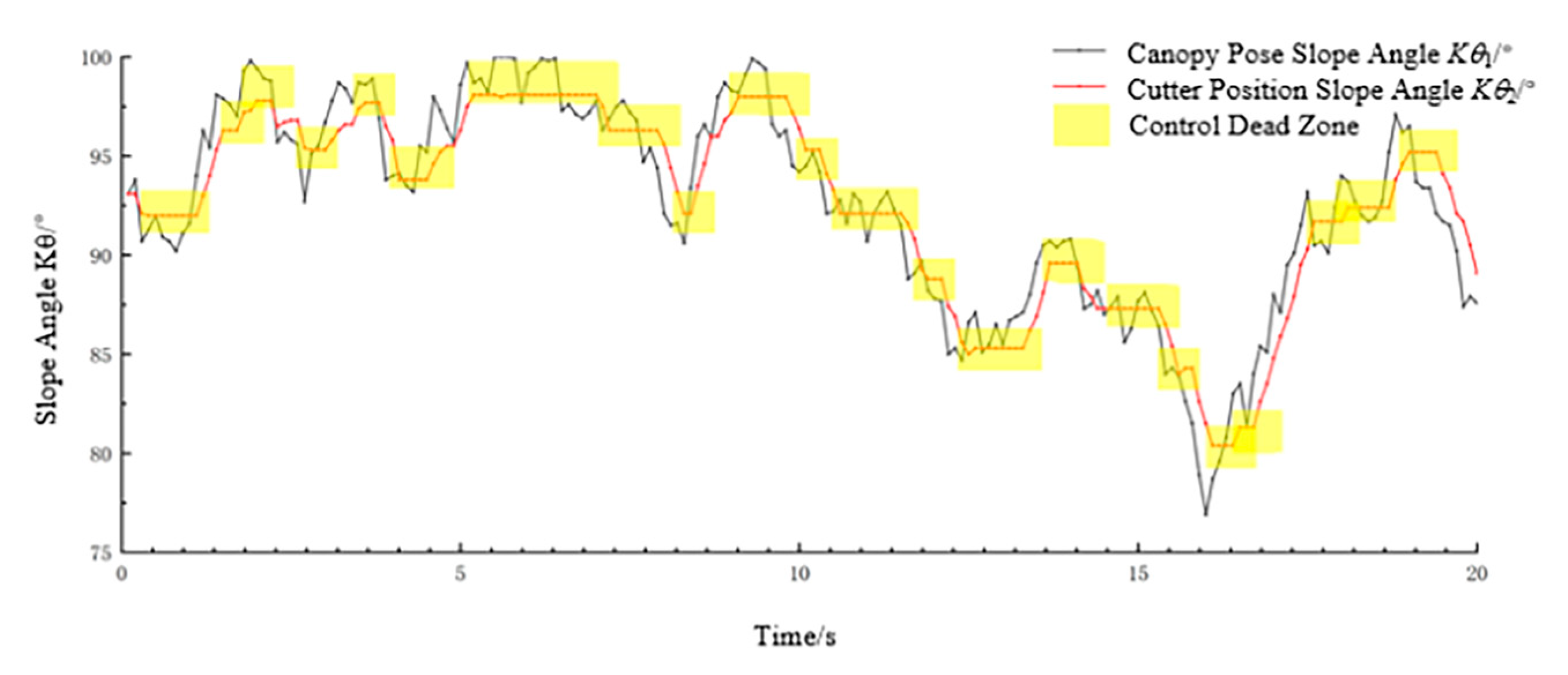
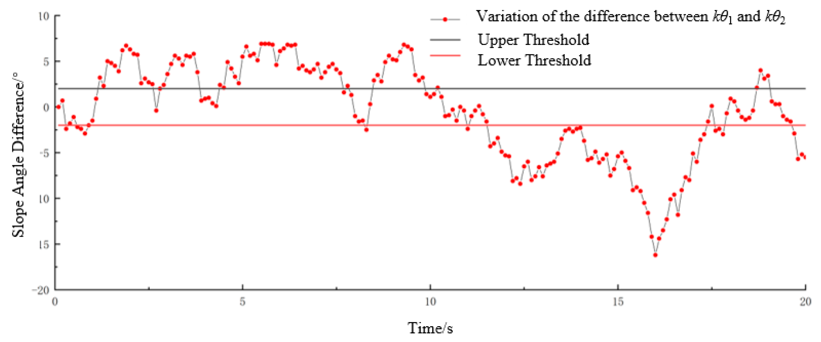
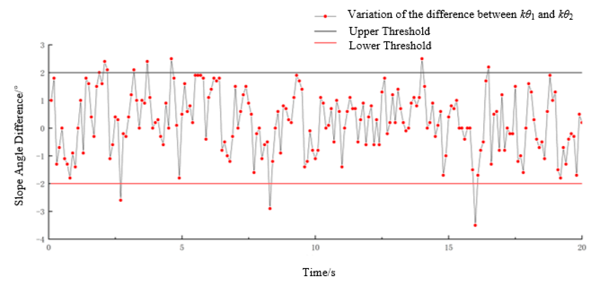
During the experimental procedure, parameter data were recorded over a 20 s interval with one data point logged every 0.1 s. The processed data are illustrated in Figure 16, Figure 17 and Figure 18.
As depicted in Figure 17, the variation trend of the canopy pose slope angle, 1, which is calculated from the canopy information required by the profiling plate, is largely consistent with the trend of the cutter’s positional slope angle, 2. Nevertheless, a distinct time lag is present. This delay is necessary because the profiling device is mounted ahead of the cutter assembly as it requires a finite duration for the cutter to reach the specific location on the canopy that is previously measured by the profiling plate. Thus, a time-delay control strategy was implemented to ensure that the actual cutting position was aligned precisely with the intended target position on the canopy profile. The high degree of consistency between the slope angle trends therefore confirms that the proposed profiling cutting platform effectively regulates the header’s pressure in response to variations in the canopy’s morphology.
Figure 18 and Figure 19 showcase a comparative analysis of the system’s performance before and after the profiling control. Before profiling, an analysis of 200 data points revealed that only 53 points, which correspond to the initial deviation angle θ between the tea canopy and the cutter, fall within the prescribed control threshold (the range for optimal cutting positions). This illustrates that the cutter operated in a favorable cutting position for only 26.5% of the total harvesting duration. After the profiling system is activated, 190 out of the 200 data points for the slope angle difference are maintained within the control threshold. This illustrates that the total time the cutter spent in an optimal cutting position increased to 95%, demonstrating a performance improvement of 68.5%. The failure to achieve 100% optimal positioning time can be primarily attributed to three factors: the linear accuracy limitations of the angle sensor, structural compliance deviations in the profiling mechanism, and variations in physical characteristics among different tea cultivars.

3.3.3. Harvesting Performance Test of the Profiling Cutting Platform Control System

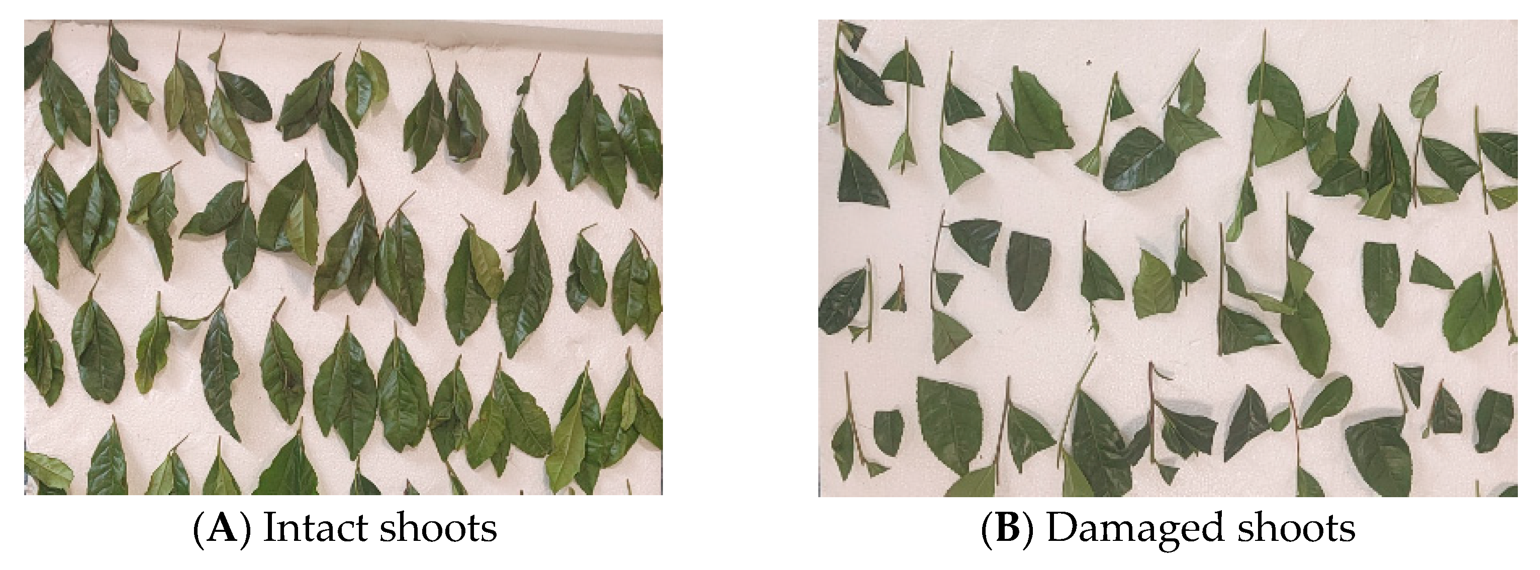
The picking quality was evaluated using the metrics listed below [22]. The integrity rate refers to the weight of intact buds and leaves to the total weight of the sample from a single experimental trial. In this study, tea shoots with minor damage (less than 1/3 of the leaf area damaged) and severe damage (more than 1/3 of the leaf area damaged) were both categorized as non-intact. In addition, the target for picking was shoots comprising one bud with two leaves, one bud with one leaf, and single buds.
The tea picking performance test was conducted on an artificially prepared tea canopy with a set inclination angle of 25° and a maximum surface undulation height of less than 50 mm. A statistical analysis was conducted on the samples of tender shoots harvested from both the inclined and undulating canopies. According to the results, the integrity rate of tea leaves harvested without the profiling system is 50.7%, while the integrity rate increases to 74.6% when the profiling system is used. This represents a 47.1% improvement in the integrity rate after profiling, as detailed in Table 2. These results showcase that the developed profiling cutting platform obtains a superior tea harvesting performance on tea canopies with both inclination and variable morphology. As shown in Figure 13, without profiling control, the cutter fails to adapt to inclined or undulating canopy surfaces, resulting in either excessive cutting depth (where blade pressure causes bud breakage at convex areas) or missed cuts (where blade detachment occurs at concave regions). Through coordinated slope control by three profiling plates, the system maintains a cutting orientation parallel to the canopy tangent plane, minimizing non-perpendicular shear between the blade edge and the tea shoots. Compared with the 4CJ-1200F intelligent tea harvester (70% integrity rate) reported in the literature [22], this system achieves a 74.6% integrity rate, which is a 4.6 percentage point improvement, further demonstrating the effectiveness of this profiling harvesting apparatus.

4. Conclusions

This study successfully designed, developed, and validated a contact-based profiling cutting platform for automatic tea harvesting. The main conclusions are as follows:
(1)
A novel contact-based profiling mechanism and its associated control method were proposed to address the challenge of poor mechanized harvesting quality on the irregular canopy morphology found in hilly tea gardens in China. This system automatically adjusts the picking header’s pose, effectively resolving the problem of the inconsistent harvesting performance.
(2)
A mathematical model was established to correlate the tea canopy’s pose with sensor signals. Based on this theoretical analysis, a parametric design was conducted for key components of the system, determining the optimal structural dimensions for the profiling plate and the selection parameters for the torsion spring.
(3)
The software and hardware for the header’s servo-control system were developed, and a functional prototype was established. Subsequent experimental validation clearly demonstrated the system’s excellent dynamic performance and harvesting effectiveness. The key quantitative results were twofold: the time the cutter spent in an optimal cutting position improved dramatically from 26.5% without profiling to 95.0% with profiling, and the integrity rate of the harvested shoots increased from 50.7% to 74.6%, a 47.1% improvement, demonstrating the system’s ability to significantly enhance harvest quality.
In conclusion, this profiling cutting platform demonstrates significant adaptability through parameter optimization, including dimensional adjustments of the profiling mechanism, stroke range modifications for the header lifting actuator, torque calibration of torsion springs, and tailored contact force models for various tea cultivars. This customizable architecture enables effective operation across diverse environments with substantial canopy morphology variations, thereby providing critical technical support for developing intelligent bulk tea harvesting equipment specifically designed for hilly and mountainous terrain applications.

Author Contributions

H.Z., N.R. and T.F. conceived and designed the experiments, H.Z. and T.F. performed the experiments; H.Z., Z.H., T.F. and G.Y. analyzed the data; H.Z., B.C. and T.F. wrote the draft manuscript; H.Z., T.F. and N.R. revised the manuscript. All authors have read and agreed to the published version of the manuscript.

Funding

This work was supported by the Integrated Pilot Project for Agricultural Machinery R&D, Manufacturing, and Promotion in Zhejiang Province, China (2024R30S24C01).

Institutional Review Board Statement

Not applicable.

Informed Consent Statement

Not applicable.

Data Availability Statement

The raw data supporting the conclusions of this article will be made available by the authors on request.

Conflicts of Interest

The authors declare no conflict of interest.

References

  1. Mei, Y.; Zhang, S. Analysis of China’s Tea Production and Domestic Sales in 2022. China Tea 2023, 45, 25–30. [Google Scholar]
  2. Mei, Y.; Liang, X. Analysis of China’s Tea Production and Domestic Sales in 2021. China Tea 2022, 44, 17–22. [Google Scholar]
  3. Weng, W. An Overview of China’s Tea Market in 2020 and First Half of 2021. China Tea 2021, 43, 74–76. [Google Scholar]
  4. Yan, J.; Hu, D.; Liu, Q.; Yu, L.; Liu, S. Research Progress and Development Trend of Tea Stripping Technology and Machinery. J. Chin. Agric. Mech. 2022, 43, 75–83. [Google Scholar]
  5. Zheng, H.; Fu, T.; Xue, X.; Ye, Y.; Yu, G. Research Status and Prospect of Tea Mechanized Picking Technology. J. Chin. Agric. Mech. 2023, 44, 28–35. [Google Scholar]
  6. Wang, Q. A Brief Discussion on Tea Picking Technology in Agricultural Technology Promotion. Friends Farmers Get Rich 2019, 66. [Google Scholar]
  7. Han, Y.; Xiao, H.; Qin, G.; Song, Z.; Din, W.; Mei, S. Studies on Develop Situations of Tea-Leaf Pickers Both at Home and Abroad. J. Chin. Agric. Mech. 2014, 35, 20–24. [Google Scholar]
  8. Li, Y. Recommended Tea Garden Management Machine for Hilly Terrain—Model 3TG-1500 High-clearance Field Management Machine. Agric. Knowl. 2015, 3. [Google Scholar]
  9. Tan, J.; Sui, S.; Gao, X.; Li, G.; Wan, X.; Jiang, J.; Luo, G.; Wei, D.; Chen, X.; Zhang, J. Mechanization Status and Development Suggestions for Tea Gardens in Hilly and Mountainous Areas. Sichuan Agric. Sci. Technol. 2023, 75–78. [Google Scholar]
  10. Dong, C.; Li, Y.; Chen, J.; Wang, M.; Jia, J.; Zhang, R.; Wang, M.; Liu, Z. A Bionic Tea Picking Cutter, Tea Picking Device and Tea Picking Method. Chinese Patent CN114009214A, 8 February 2022. [Google Scholar]
  11. Li, Y. Research on Visual Detection and Positioning Technology of Tea Picking Robot. Ph.D. Thesis, Zhejiang Sci-Tech University, Hangzhou, China, 2022. [Google Scholar]
  12. Tang, Y.; Han, W.; Hu, A.; Wang, W. Design and Experiment of Intelligent Tea-plucking Machine for Human Riding Based on Machine Vision. Trans. Chin. Soc. Agric. Mach. 2016, 47, 15–20. [Google Scholar]
  13. Zhao, R.; Bian, X.; Chen, J.; Dong, C.; Wu, C.; Jia, J.; Mao, M.; Xiong, Y. Development and Test for Distributed Control Prototype of the Riding Profiling Tea Harvester. J. Tea Sci. 2022, 42, 263–276. [Google Scholar]
  14. Wu, M.; Huan, X.; Chen, J.; Dong, C.; Shao, B.; Bian, X.; Fan, G. Research and Experiment on Profiling Method of Tea Picker Based on Fusion of 2D-LiDAR and Attitude and Heading Reference System. J. Tea Sci. 2023, 43, 135–145. [Google Scholar]
  15. Yan, J. Optimal Design of Profiling Tea Harvester and Its Coordination with Tea Garden Management. Ph.D. Thesis, Anhui Agricultural University, Hefei, China, 2019. [Google Scholar]
  16. Hu, J.; Chen, W.; Chen, B. Tea Harvester (SV100 Arc-Shaped Two-Person). Chinese Patent CN306011996S, 25 August 2020. [Google Scholar]
  17. Geng, A.; Zhang, M.; Zhang, J.; Zhang, Z.; Gao, A.; Zhang, J. Design and Experiment of Automatic Control System for Corn Header Height. Trans. Chin. Soc. Agric. Mach. 2020, 51, 118–125. [Google Scholar]
  18. Peng, Q.; Ma, J.; Song, H.; Lv, A. Research on Cotton Height Profiling Device. Jiangsu Agric. Sci. 2016, 44, 356–358. [Google Scholar]
  19. Tang, X.; Liu, T.; Huang, M. Calculation and Experimental Study on Torsional Stiffness of Torsion Spring. J. Nanchang Univ. (Eng. Technol.) 2020, 42, 249–253. [Google Scholar]
  20. Jiang, X.; Huang, Z.; Mu, Y. Influence of Ovality of Cylindrical Helical Torsion Spring Coil on Stress and Stiffness. Mach. Build. Autom. 2022, 51, 9–12. [Google Scholar]
  21. Wang, Q.; Lin, H.; Liao, P. Shearing Mechanical Properties of Tea Stem. J. Fujian Agric. For. Univ. (Nat. Sci. Ed.) 2022, 51, 428–432. [Google Scholar] [CrossRef]
  22. Han, Y.; Song, Z.; Chen, Q. Design and Experiment of 4CJ-1200F Intelligent Tea Plucking Machine. J. Intell. Agric. Mech. 2022, 3, 1–6. [Google Scholar]
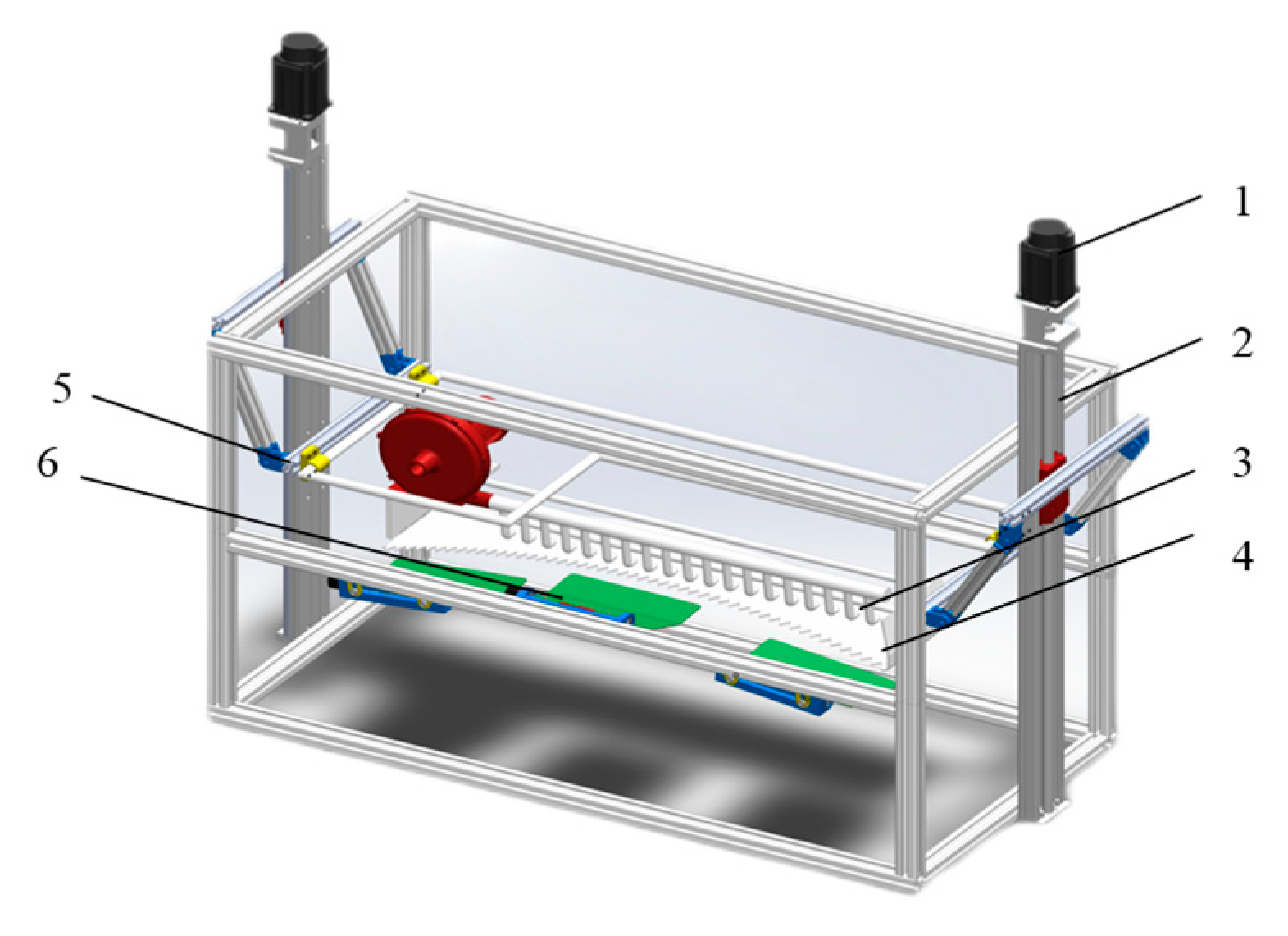
Figure 1. Schematic of the profiling cutting platform: 1. motor; 2. ball screw linear module; 3. air duct; 4. cutting blade; 5. linkage mechanism; 6. canopy profiling feedback mechanism.
Agriculture 15 01866 g001
Figure 2. Principal diagram of the profiling cutting platform control system.
Agriculture 15 01866 g002
Figure 3. Dimensional diagram of the tea canopy surface profiling device: 1. mounting shaft; 2. profiling plate; 3. fixing frame; 4. torsion spring; 5. angle sensor.
Agriculture 15 01866 g003
Figure 4. Schematic diagram of the contact between the profiling device and the tea canopy surface.
Agriculture 15 01866 g004
Figure 5. Movement diagram of the profiling plate in contact with the canopy surface.
Agriculture 15 01866 g005
Figure 6. Schematic diagram of the force on the profiling plate.
Agriculture 15 01866 g006
Figure 7. Profiling control strategy for profiling cutting platform.
Agriculture 15 01866 g007
Figure 8. Installation diagram of the tea canopy surface imitation device.
Agriculture 15 01866 g008
Figure 9. Slope information of the tea canopy surface.
Agriculture 15 01866 g009
Figure 10. Slope information of the profiling cutting platform.
Agriculture 15 01866 g010
Figure 11. Principle of profiling cutting platform pose adjustment.
Agriculture 15 01866 g011
Figure 12. Control flow chart.
Agriculture 15 01866 g012
Figure 13. Prototype test of the profiling cutting platform.
Agriculture 15 01866 g013
Figure 14. Corresponding speed data of the 30 mm motor for the header lifting.
Agriculture 15 01866 g014aAgriculture 15 01866 g014b
Figure 15. Corresponding speed data of the 50 mm motor for the header lifting.
Agriculture 15 01866 g015
Figure 16. The slope and inclination angle of the profiling cutting platform pose control experiment change over time.
Agriculture 15 01866 g016
Figure 17. Changes in the canopy morphology and the deviation of the profiling cutting platform over time before profiling.
Agriculture 15 01866 g017
Figure 18. Changes in the canopy morphology and the deviation of the profiling cutting platform over time after profiling.
Agriculture 15 01866 g018
Figure 19. Tea samples after profiling and picking.
Agriculture 15 01866 g019
Table 1. Header response speed meter.
Trial No.MotorPlatform Ascent Distance/mmSettling Time/sAdjustment Speed/(mm·s−1)
11300.93490.97
2301.17689.40
21500.99191.31
2501.12490.30
Table 2. Results of the picking experiment.
Trial No.Without ProfilingWith Profiling
Sample Weight/kgIntact Shoots/kgIntegrity Rate/%Sample Weight/kgIntact Shoots/kgIntegrity Rate/%
10.0650.03653.6%0.060.04473.3%
20.0720.03548.8%0.0690.05376.5%
30.0760.03850.6%0.0730.05271.5%
Average0.0710.03650.7%0.0670.05074.6%
Disclaimer/Publisher’s Note: The statements, opinions and data contained in all publications are solely those of the individual author(s) and contributor(s) and not of MDPI and/or the editor(s). MDPI and/or the editor(s) disclaim responsibility for any injury to people or property resulting from any ideas, methods, instructions or products referred to in the content.