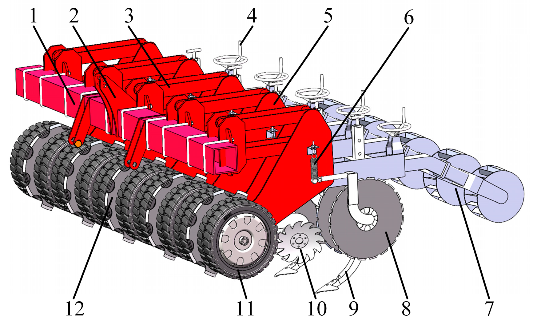
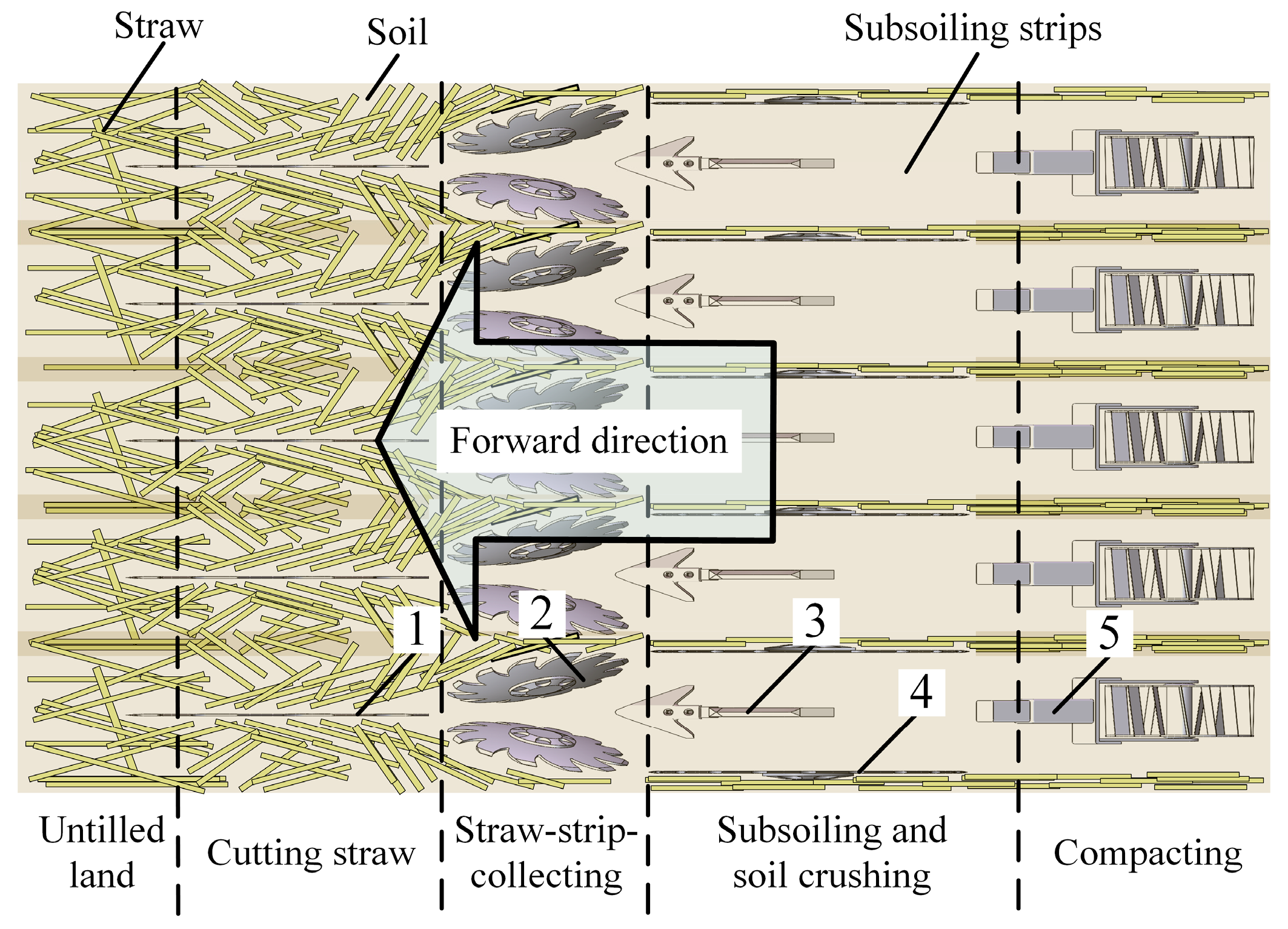
2.2.1. Design of Monomer Profiling Mechanism
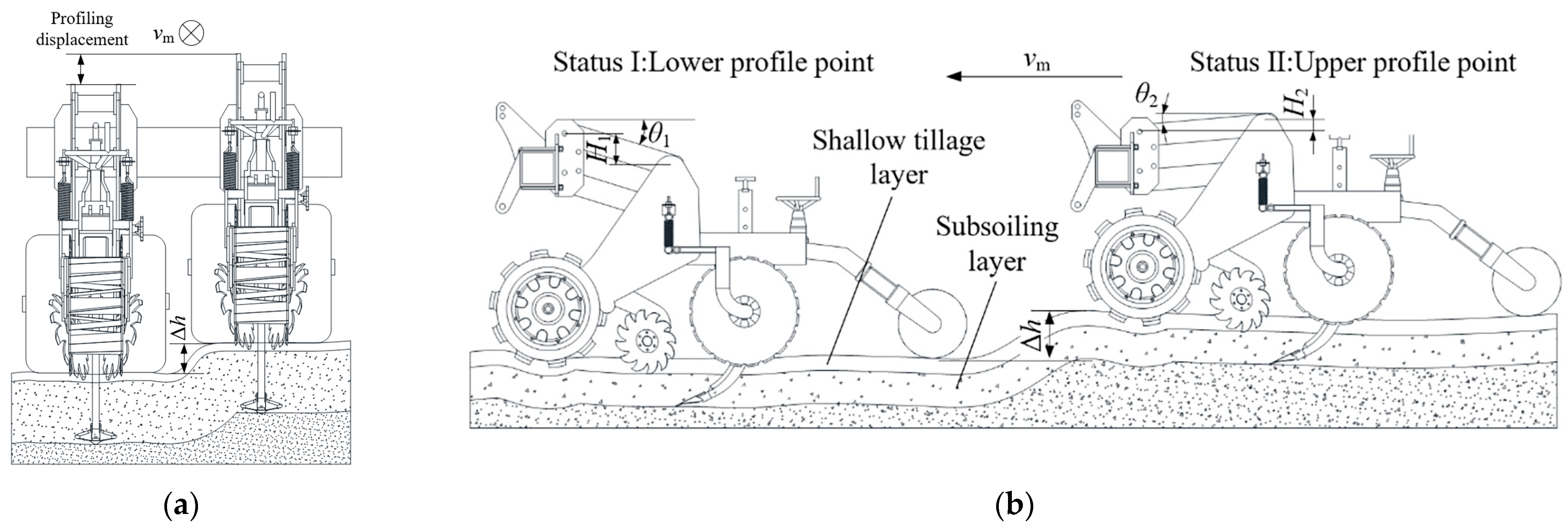
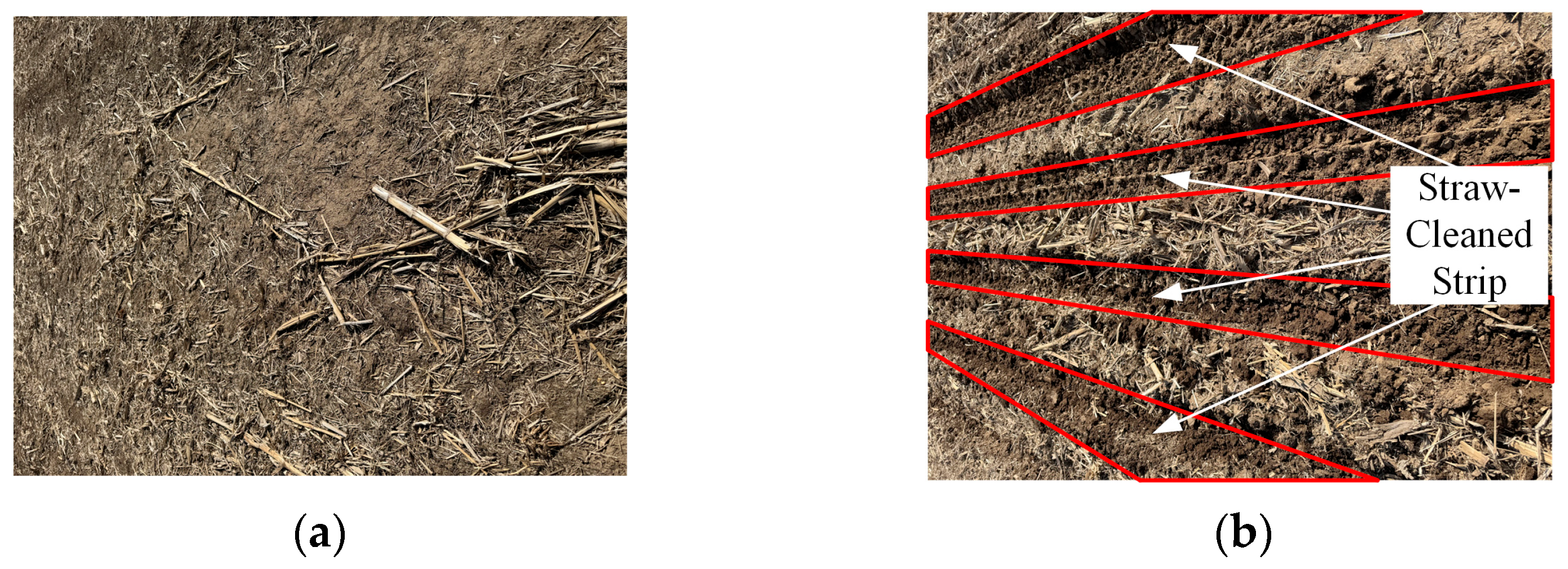
In the combined “straw strip collecting-strip subsoiling” mode, consistent straw removal performance and subsoiling depth across each individual strip are critical for successful subsequent seeding. Therefore, a monomer-based profiling mechanism was designed for each tillage unit. The implement features five independent monomer units, each performing both straw-cleaning and subsoiling functions. Each unit employs a parallelogram linkage to passively follow terrain variations. The principle is illustrated in
Figure 3. During operation, each unit independently adapts to transverse surface undulations within its strip, maintaining close contact between its working components and the ground. This ensures consistent straw removal and tillage depth. When encountering longitudinal terrain undulations, the frame height undergoes abrupt changes in the vertical plane. The profiling mechanism accommodates these height changes, maintaining ground contact and reducing traction resistance, thereby improving operational efficiency.
From
Figure 3, the total profiling displacement
H of the mechanism is:
where
H1 and
H2 are the lower profiling displacement and the upper profiling displacement, respectively;
L0 is the length of the profiling link; and
θ1 and
θ2 are the lower profiling angle and the upper profiling angle, respectively.
Given the substantial tillage depth and reliance on implement weight for passive ground contact, longer profiling linkages and a larger total profiling displacement were employed. This configuration shifts the center of gravity rearward, enhancing stability [
23]. Both profiling angles were set to 15°, with mechanical stops pins limiting the range. The total profiling displacement
H was set to 320 mm. Substituting these values into the Equation (1) and rounding, the final linkage length was 620 mm, with a vertical distance between the linkages of 200 mm.
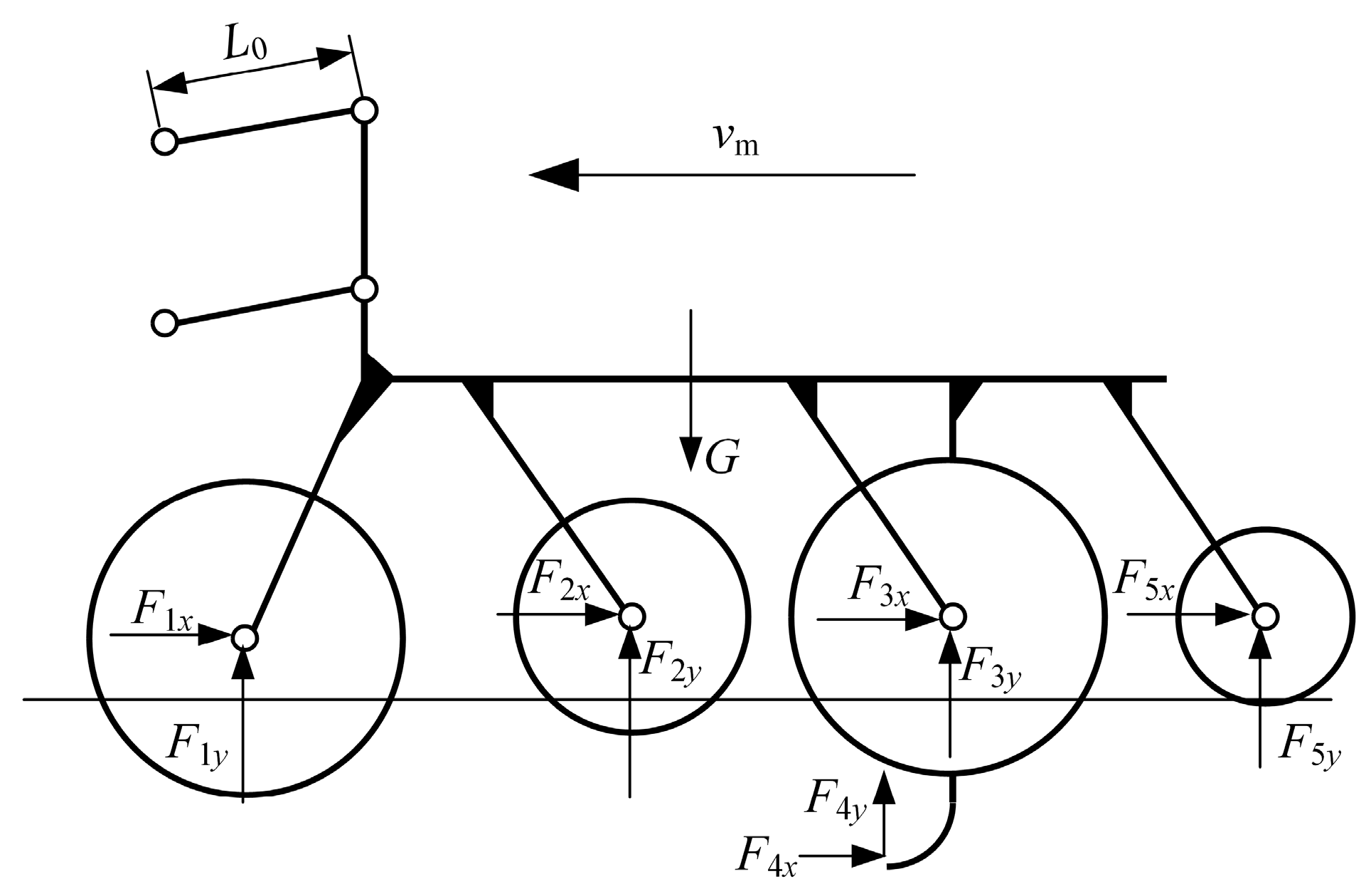
The force analysis of the profiling mechanism during operation is presented in
Figure 4. As the mechanism lacks a dedicated profiling spring, sufficient machine and implement weight is required to ensure ground contact of the working parts. This condition is expressed as:
where
G is the self-weight of the MPSTM; and
F1y~
F5y are the vertical component forces exerted by the stubble cut notch disc and depth-limiting wheel, SCD, soil-cutting knife, subsoiler shovel and compacting device, respectively.
Each monomer unit has a base weight of approximately 3000 N, sufficient for most passive profiling scenarios. However, as the required contact force varies with operational speed and soil conditions, additional counterweights may be necessary to ensure adequate ground contact under all operating conditions.
2.2.2. Design of Stubble Clean Disc (SCD)
Under high-residue return conditions, the random distribution of straw increases soil resistance heterogeneity. This compromises both the consistency of subsoiling depth and the uniformity of soil fissure formation. As a precursor operation within the combined mode, stubble cleaning removes residue and stubble from the strip, creating a more uniform soil environment for subsequent subsoiling. The SCD is the core component for this task, and its design critically influences cleaning performance.
Key structural parameters, illustrated in
Figure 5, include the diameter
D, the curvature radius
ρ, the tooth thickness
δ, the tine radius
r, and the tine height
l.
For
D, the
Agricultural Machinery Design Manual recommends:
where
K is the ratio of diameter to depth, with a range from 5 to 7, and
h is burial depth of SCD. Assuming
h of 50 mm,
D was set to 330 mm.
For ρ, a large value results in a disc approximating a flat plate with weak soil-turning capability. Conversely, a small radius enhances performance but increases draught resistance. Based on empirical data, ρ = 600 mm was selected.
The
δ determines the operational reliability of the SCD and must be sized according to the anticipated working load. An empirical formula for general working conditions is:
Typical thickness values range from 3.5 to 6 mm. Since the SCD operates near the soil surface for shallow tillage, a greater thickness is warranted. After substituting relevant parameters into the formula and rounding, a final δ of 3.5 mm was chosen.
The tines primarily function to deflect whole straw laterally to both sides. The r and l of the tines influence straw movement. Consequently, these parameters were determined based on the straw movement analysis presented in the following sections.
- 2.
Space Installation Parameters
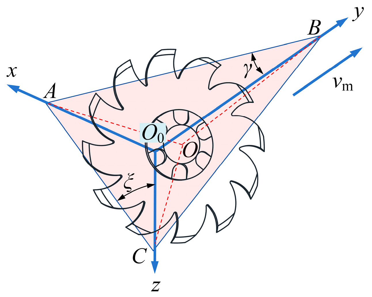
To define the spatial orientation, coordinate system
O0xyz is established as shown in
Figure 6. The
y-axis aligns with forward direction and lies on the machine’s symmetry plane, the
x-axis is perpendicular to
y and parallel to the ground, and the
z-axis is vertical. The disc surface intersects the coordinate axes at points
A,
B, and
C, defining deflection angle
γ and inclination angle
ξ. The horizontal distance between the centers of the two discs is the installation spacing
L. Based on disc harrow operational references,
γ typically ranges from 6° to 25°. For
ξ, the concave disc surface must face the soil surface to effectively clean straw; thus, an initial range from 0° to 90° was considered.
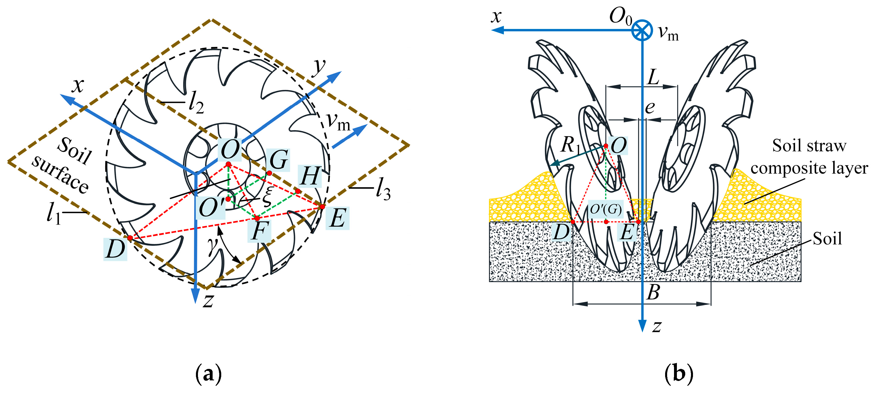
Different installation parameters influence the effective straw-cleaning width of the SCD. As shown in
Figure 7, consider a stationary SCD penetrated into the soil. The line
DE represents the intersection between the disc surface and the soil surface. Within the soil surface plane, lines
l1 and
l2 pass through
D and
E, respectively, and are parallel to the
x-axis, while
l3 passes through E and is parallel to the
y-axis. The projection of the disc center
O onto the soil surface is point
O′, and a parallel line is drawn through
O′ to intersect
DE at
F. The projection of the radius
OE onto
l3 is the line segment
GE. It can be seen from the figure that the static straw-cleaning width can be expressed as:
where
B is the static cleaning width,
lDE and
lGE are, respectively, the lengths of line segments
DE and
GE, and
L is the installation spacing of the two SCDs.
Utilizing geometric relationships and the power-of-a-point theorem (as shown in
Figure 7), the static cleaning width
B is derived as:
where
R is the SCD radius.
Since the disc centers must be above the ground surface and cannot overlap along the
x-axis, a missed cleaning region exists. The width of this region is:
where
e is the width of the missed cleaning region.
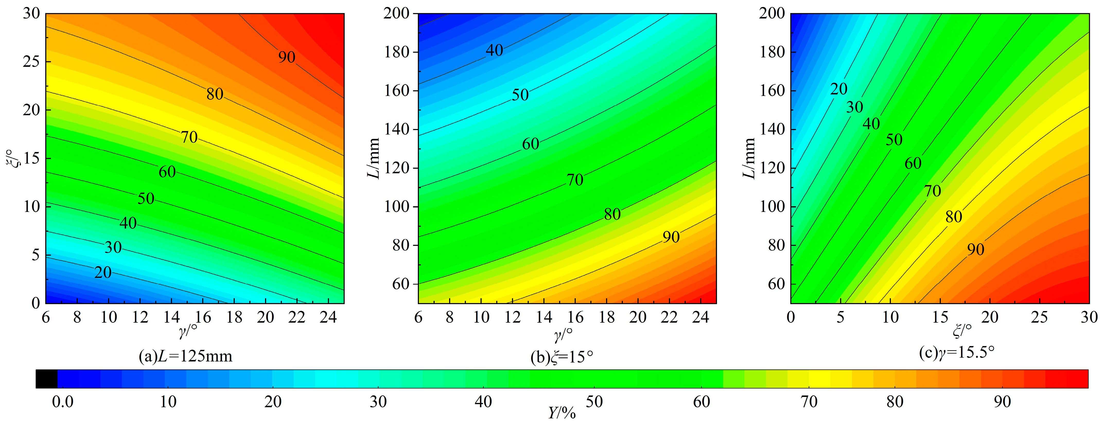
Equations (6) and (7) demonstrate that SCD cleaning performance is influenced by γ, ξ and L. A small L may cause disc interference, whereas a large L increases the e of the missed cleaning region. Therefore, based on theoretical analysis and practical considerations, L was constrained to the range of 50–200 mm.
- 3.
Analysis of Straw-Strip-Collecting Process
During soil engagement, the rotating SCD undergoes three key operational phases:
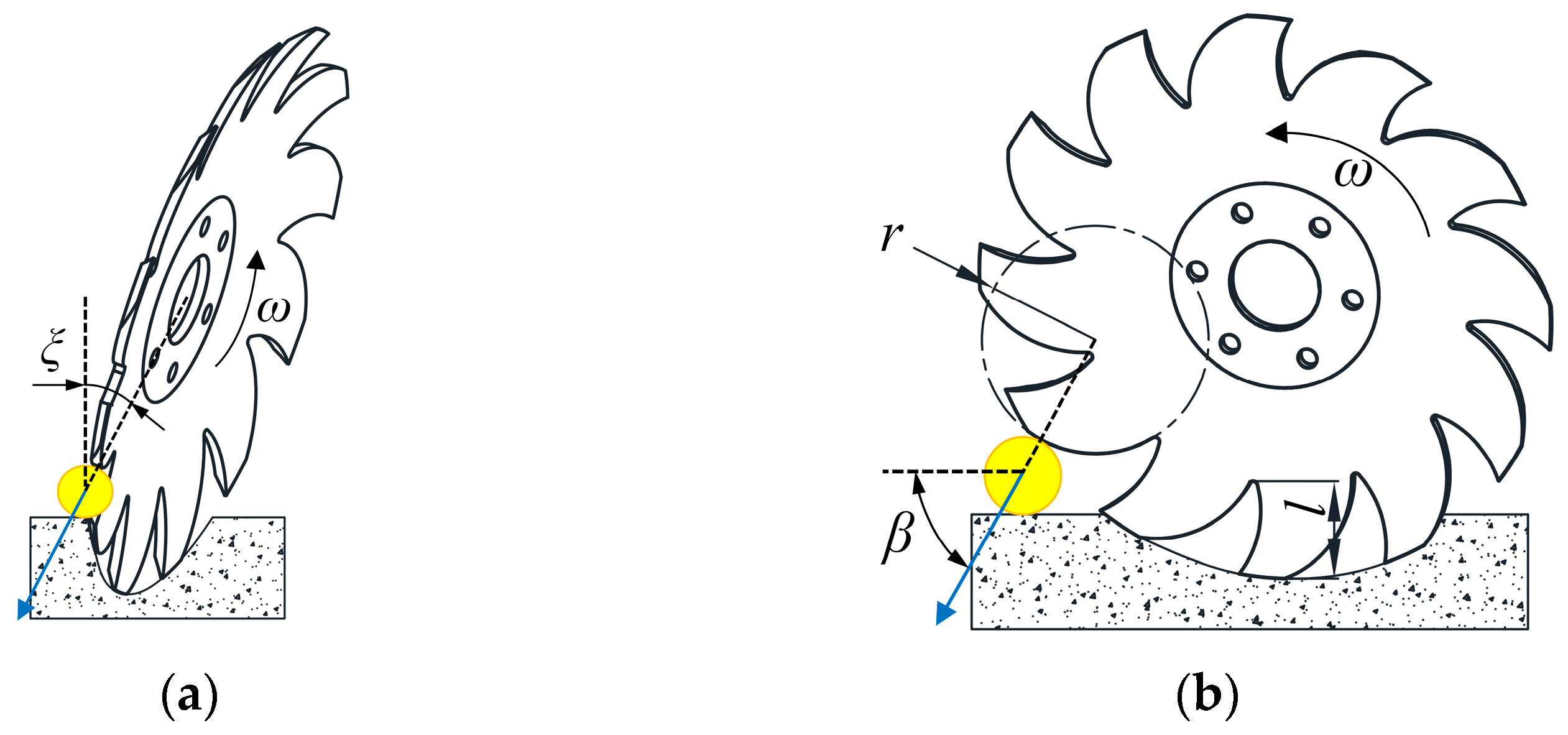
The operational process and straw-force interactions during this phase are illustrated in
Figure 8. Here, the tines press straw downward into the soil layer. To ensure good stubble-cleaning performance and structural strength, the tine radius
r is selected as 60 mm [
24].
The forces exerted by the SCD on the straw can be resolved in both the front and side views.
Front view: Assume the tine contact surface is perpendicular to the tangential velocity direction and passes through the centroid of the straw. The resultant force forms an angle ξ with the vertical direction. As ξ increases, the horizontal component of the force increases. If this horizontal component exceeds the static friction between the straw and soil, the straw slides towards the convex side of the disc, leading to missed cleaning.
Side view: Assume the force line between the tine and straw passes through the tine center and the straw centroid. The resultant force forms an angle α with the horizontal direction. After contacting the straw, the outermost point of the tine tends to slide forward relative to it. For a fixed tine radius r, the angle α decreases with decreasing tine height l. This increases the likelihood of sliding and potential blockage.
To prevent straw slippage and ensure effective engagement, self-locking conditions must be satisfied in both views. These conditions are:
where
φ is the friction angle between the straw and the ground.
According to ref. [
25],
ξ should be constrained within the range from 0° to 30°. Based on geometric constraints, a tine height
l of 55 mm ensures that the
α satisfies the self-locking condition in the side view.
During this phase, the tines penetrate the soil surface slightly. This disturbs the upper soil layer, achieving shallow tillage and reducing surface soil compaction. Simultaneously, straw and soil rotate continuously with the SCD, moving towards the ejection point
D where they are thrown out. The magnitude and direction of the velocity at point
D affect the trajectory height and side-throwing distance. As shown in
Figure 9, the velocity instantaneous center theorem shows that the angular velocity of the disc and the velocity at point
D are:
where
ω is the angular velocity of SCD,
v1 is the component velocity in SCD plane,
vm is the initial forward speed of SCD, and
vD is the absolute linear velocity at point
D of SCD.
After leaving point
D, the straw possesses the absolute velocity
vD. Modeling the straw as an ideal particle, its velocity components in the spatial coordinate system are:
where
vDx,
vDy, and
vDz are respectively the component velocities of
vD along the
x,
y, and
z axes.
The lateral throwing distance is expressed as:
where
L1 is the distance of straw lateral throwing, and
t is the straw’s airborne time.
During this dynamic ejection phase, the effective cleaning width exceeds the static width
B. This defines the dynamic cleaning width
B’, calculated as:
where
B’ is the dynamic cleaning width.
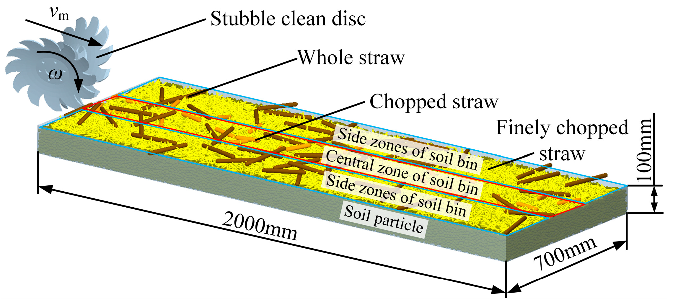
Equation (12) further confirms the influence of γ, ξ, and L on cleaning performance. The interactions among these parameters are complex, precluding the determination of optimal values based solely on theoretical analysis. As the feasible parameter ranges were established in the preceding sections, simulation methods were employed to evaluate SCD operational performance across various parameter combinations and to conduct optimization accordingly.
2.2.3. Design of Strip Subsoiling Mechanism
Full-width subsoiling operations in maize fields face significant limitations due to their high draft resistance, extensive soil disturbance, and substantial energy consumption. In contrast, strip subsoiling targets the soil layer directly beneath the seeding strip (following the shallow tillage performed by the SCDs) to achieve the vertical alleviation of soil compaction.
During subsoiling, the subsoiler shovel penetrates the soil. Its action generates crescent-shaped fractures in the upper soil layer and rectangular fractures in the deeper soil [
26]. Given that the crescent-shaped failure range is relatively narrow and that the strip width is restricted by the soil-cutting knives, the overall fracture area can be approximated as a rectangle, as shown in
Figure 10a. When the Subsoiler shovel advances, its tip wedges into the soil and the shovel surface applies vertical tensile and shear forces on the soil, as illustrated in
Figure 10b. According to the Mohr–Coulomb criterion [
27], the shear stress
τ satisfies:
where
τ is the soil shear stress,
C is the soil cohesion,
σ is the soil normal stress, and
φi is the internal friction angle of soil.
When
τ exceeds the soil shear strength, it induces shear failure and brittle fracture, forming a fissure network that penetrates the plow pan. Under ideal conditions, the fissure depth should exceed the subsoiling depth
HS. The formation of such fissures greatly enhances vertical permeability of the soil and causes an upward heave height Δ
H in the longitudinal-vertical plane, resulting in changes in soil bulk density. According to the principle of mass conservation:
where
ε0 and
εS are, respectively, the soil bulk densities before and after the operation.
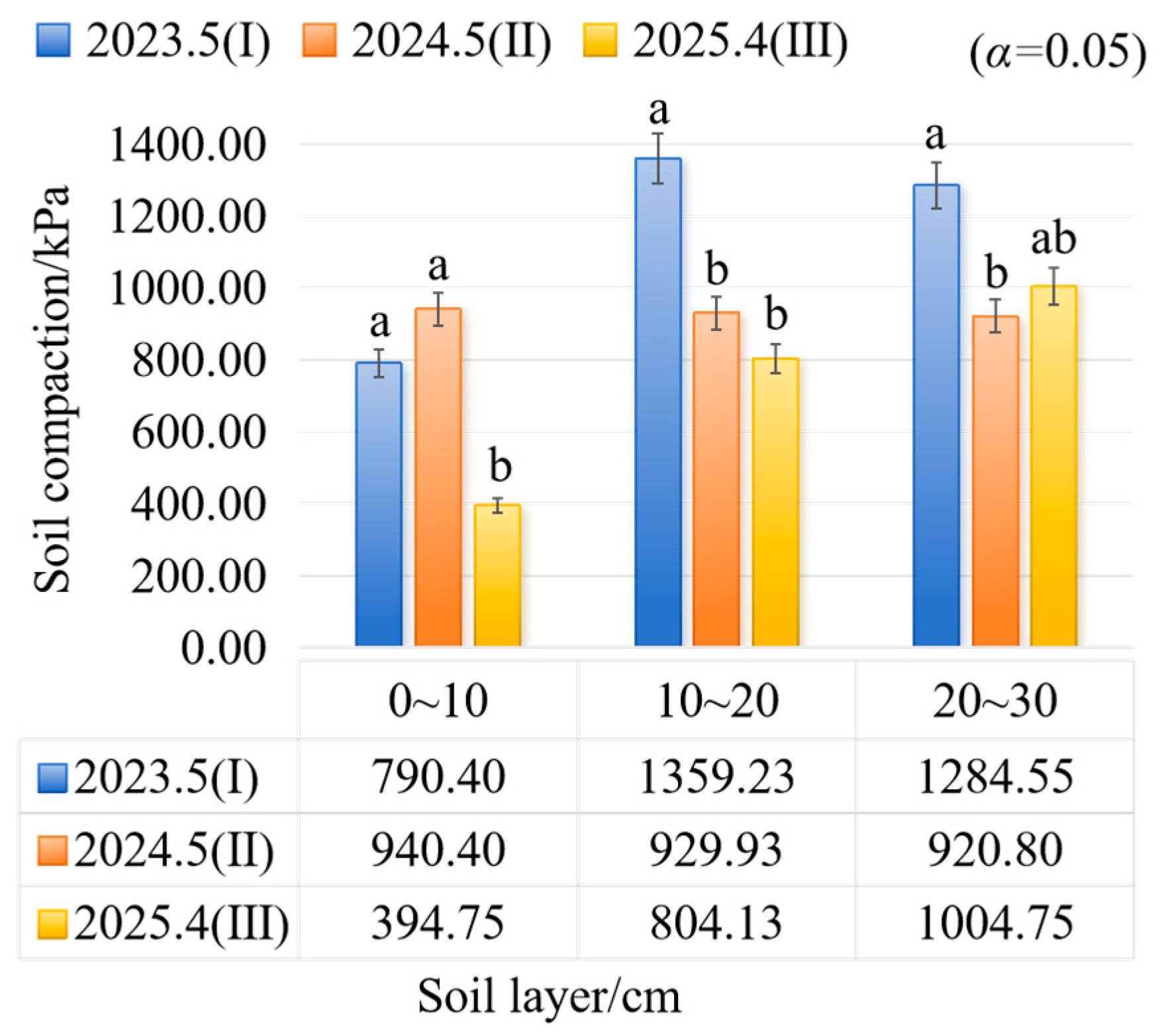
Soil compaction is positively correlated with bulk density [
28]. Hence, from the above equation, a larger Δ
H indicates a lower post-operation bulk density and a greater reduction in soil compaction. The relative reduction is expressed as:
where Δ
P is the relative decrease in soil compaction, and
P0 and
PS are, respectively, the soil compaction before and after the operation.
During subsoiling, if the shovel is flanked by unbounded side components, the surface disturbance pattern is approximately fan-shaped. The maximum disturbance width W can be expressed as [
29]:
where
LS is the length of subsoiler shovel handle.
This indicates that the disturbance width is determined not only by shovel geometry but also by subsoiling depth. To ensure effective fragmentation of the topsoil within the strip, the disturbance width should exceed the strip width of 200 mm. Addressing the need for reduced straw entanglement and minimized tillage resistance under conservation tillage, a combination of medium shovel and dual-wing subsoiling shovel is adopted according to the Chinese national standard
GB/T 24675.2-2024 Conservation Tillage Equipment—Part 2:Subsoiler [
30]. The shovel is 300 mm in length and 25 mm in width. For ensuring sufficient deep-soil disturbance while reducing operating resistance, 150 mm-wide dual-wing shovels are selected. Tungsten carbide coating is applied to the shovel tips to enhance wear resistance, enabling adaptation to high-residue return conditions. To effectively break the plow pan, a mid-position subsoiling depth of 300 mm is selected, with two adjustable levels in increments of 90 mm depending on field conditions. Substituting into Equation (16), it is found that under common ranges of soil friction angle [
31,
32,
33], the selected parameters satisfy the disturbance width requirements for strip subsoiling.
To cut the upper soil layer clods and finely chopped straw after subsoiling, constrain the strip width, and prevent straw fallback, soil-cutting knives are mounted on both sides of the subsoiler shovel. Based on Equation (3), the knives diameter is set to 600 mm. For improved crushing of soil clods, 20 notches with a depth of 17 mm are selected. To avoid interference with the wedge-shaped structure formed by the subsoiling shovel and ensure adaptability to uneven surfaces, a spring-based profiling mechanism is used to control the penetration depth of the soil-cutting knives.
