Abstract
Aiming at key issues in harvesting film-covered potatoes in hilly and mountainous areas—incomplete residual film collection, poor potato–soil separation, and high damage from potato-collecting devices—this study developed a crawler self-propelled potato harvester suitable for these regions. This study first expounds the overall structure and working principle of the potato harvester and then conducts principal analysis and structural design for key components (film-collecting device, digging device, primary conveying and separating device, secondary conveying and separating device, and intelligent potato-collecting device) from the perspectives of material force and movement. Finally, field performance tests were carried out in Huangzhong County, Xining City, Qinghai Province. The test results show that the machine can achieve an operation effect with a potato harvest loss rate of 2.4%, a potato damage rate of 1.4%, an impurity content rate of 2.8%, a skin-breaking rate of 2.7%, and a residual film cleaning rate of 89.6%, meeting the potato harvesting needs of this region. The lightweight self-propelled crawler potato harvester designed in this paper can realize functions such as residual film collection, potato–soil vibration separation, manual auxiliary sorting, and intelligent potato boxing, providing technical and equipment references for the harvesting of film-covered potatoes in complex terrain areas.
1. Introduction
The potato is an annual herbaceous plant belonging to the genus Solanum in the family Solanaceae. It has the advantages of drought resistance, barrenness tolerance, high water use efficiency, and high economic benefits [1,2]. Rich in nutrients, the potato is known as the “underground apple” [3,4,5], and it is also an important industrial raw material crop and feed crop [6]. With the implementation of the strategy of making potatoes a staple food, coupled with its growth advantages of being tolerant to barrenness and high levels of cold, it has become the fourth largest staple food in China [7,8,9]. In 2024, the total planting area of potatoes in China was approximately 4.697 million hectares, with an annual total output of about 19.09 million tons. China ranks first in the world in both potato planting area and total output. However, affected by factors such as the complex environment of potato planting areas in China and non-standard planting methods, the mechanized harvesting rate in China is only 32%. Specifically, the special geographical environment of hilly and mountainous areas has largely restricted the progress of mechanized potato harvesting in China [10].
The terrain in hilly and mountainous areas is intricate, with field roads often being narrow and rugged. Such topographical conditions have adverse impacts on potato harvesting in multiple ways: due to their large size and weight, mature large-scale harvesters are difficult to transport on narrow and rugged roads and cannot smoothly enter fields for operation. In addition, hilly and mountainous areas mostly have heavy clay soils, which tend to adhere to potato tubers during harvesting. This increases the difficulty of separating potatoes from soil, leading to higher energy consumption and poorer performance of separation devices, and easily causes tuber damage or omission. Meanwhile, potato cultivation in many hilly and mountainous areas adopts the full-film mulching method. Although full-film mulching can increase yields, residual films are prone to entangling and blocking the separation devices during harvesting, interfering with the process of potato–soil separation [11]. The combined effect of residual films and heavy clay soils further exacerbates the difficulty of harvesting. These factors together result in numerous challenges in potato harvesting operations in hilly and mountainous areas, making it difficult to improve the mechanization level and restricting the development of the local potato industry [12].
Potato combine harvesting technology and equipment are well-developed in Europe and America. Large harvesters designed for plains, such as Germany’s GRIMME SE75, incorporate multiple separation units and strip pickers to effectively separate potatoes from weeds and stones [13]. Belgium’s AVR SPIRIT9200, another large-scale model, features a 6.5-ton capacity hopper, full hydraulic drive, and an adaptable separation module for various soil conditions [14]. An American Double L 973 requires a 295-horsepower tractor and achieves a maximum throughput of 300 tons per hour [15]. These large combines offer comprehensive functionality and high efficiency over extensive areas. However, their large turning radius and limited maneuverability render them unsuitable for small plots and complex terrains, such as those prevalent in hilly regions [16].
Chinese scholars have also carried out extensive research on potato harvesting equipment and technologies in hilly and mountainous areas. Yang et al. [17] developed the 4UJ-180A potato picker and bagger, featuring a soil excavation shaft, flexible conveyor, and hydraulic control system. It uses a rubber bionic deflector to minimize collision-induced damage. To tackle the issue of sticky soil separation in such areas, Zhang et al. [18] designed a harvester integrating wave-type and roller-set separation mechanisms. By increasing the effective separation length and contact area of potato–soil mixtures, it achieves the removal of clay and heavy soil. Aiming at the complex terrain in the mountainous regions of southern Ningxia, Ma et al. [19] developed an integrated machine for potato harvesting and residual film recovery. Using a digging shovel, S-shaped soil–potato shaking chain, and pneumatic film recovery mechanism, it completes both tasks in one operation. Dai et al. [20] added a floating pneumatic film-rolling auxiliary device to resolve the problems of residual film clogging and retention in conveying and rolling devices of combined recycling machines.
It is evident that China has conducted research in both the fields of potato harvesting and residual film recycling for potatoes in hilly and mountainous areas. Nevertheless, existing research is relatively deficient in addressing the specific application scenario of cultivation in hilly and mountainous areas. Consequently, targeting the unique agronomic requirements of hilly and mountainous areas, this study adopts the integrated approach encompassing the processes of harvesting, digging, separating, and loading, integrating residual film collection, potato–soil digging, potato–soil separation, manual auxiliary sorting, and potato packing into one, and designing a self-propelled potato harvester. Harvesting tests were carried out in Huangzhong District, Xining City, Qinghai Province to verify the performance of the designed machine.
2. Materials and Methods
2.1. Overall Structure and Working Principle of the Whole Machine
2.1.1. Composition of the Overall Structure
Based on potato cultivation agronomy in hilly and mountainous areas, a self-propelled potato harvester was designed (Figure 1). It consists of two main components: the chassis walking system and the working component system. The chassis system comprises an engine, generator, gearbox, crawler system, fuel tank, and hydraulic system. The working component system includes a film-collecting device, depth-limiting and soil-crushing device, potato digging device, primary and secondary potato–soil conveying and separating devices, sorting platform, and potato collection box.
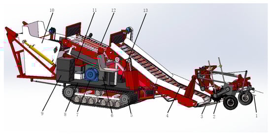
Figure 1.
3D Structural schematic of self-propelled potato harvester: 1. Film-collecting device; 2. Depth-limiting soil crushing device; 3. Excavating shovel; 4. Primary potato–soil conveying and separating device; 5. Crawler system; 6. Gearbox; 7. Generator; 8. Sorting platform; 9. Fuel tank; 10. Potato collection box; 11. Diesel engine; 12. Secondary potato–soil conveying and separating device; 13. Hydraulic system.
2.1.2. Working Principle
Figure 2 illustrates the harvester’s power transmission. As a self-propelled machine, its total power is derived from the diesel engine (1), with other devices receiving power through gear and belt transmission (3). In the figure, (4) denotes an AC generator, which is powered by the diesel engine. A soil shaking device is positioned at the front. Its fork tooth rotating shaft (16) utilizes sprocket–chain transmission driven by a hydraulic motor, separating and collecting plastic film before harvesting. For primary potato separation, the power output shaft (6) of the primary elevator is driven by a one-way hydraulic motor (5). Electric current flows through the first controller (7) to the electric motor (8), which drives the vibration camshaft. The secondary separation drive shaft (9) is powered by the second electric motor. It connects to the soil conveyor belt drive shaft (10) via sprockets and chains, facilitating simultaneous operation during secondary separation. The driving power of the harvester is transmitted from the diesel engine to the bidirectional hydraulic motor (12), adjusted by the gearbox (13), and ultimately delivered to the crawler chassis drive shaft (14). The hydraulic push rod (17), regulated by the solenoid valve (15), provides power for lifting the potato collection box. The third electric motor supplies power to the scraper conveyor belt within the box via its drive shaft (11).
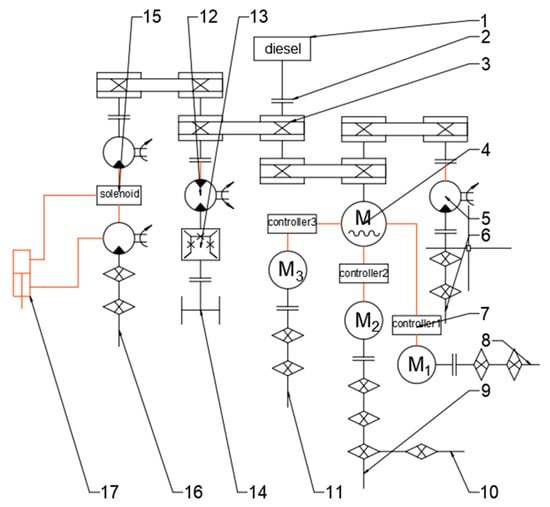
Figure 2.
Schematic diagram of the power transmission mode of the potato harvester (the red circuit is electro-hydraulically controlled, and the black circuit is mechanically controlled). 1. Diesel engine; 2. Bearing; 3. Gear and belt drive; 4. Alternating current (AC) generator; 5. Unidirectional hydraulic motor; 6. Power output shaft of primary elevating device; 7. No. 1 current controller; 8. Electric motor; 9. Secondary separation drive shaft; 10. Soil conveyor belt drive shaft; 11. Scraper conveyor belt drive shaft; 12. Bidirectional hydraulic motor; 13. Gearbox; 14. Crawler chassis drive shaft; 15. Solenoid valve; 16. Soil-shaking fork tooth rotating shaft; 17. Hydraulic push rod.
During operation, the film-collecting device first shakes off soil and potato vines from the residual film, then rolls the film onto the film-rolling roller. The depth-limiting and soil-crushing device utilizes a roller to break up large surface clods and limit working depth. The excavation shovel lifts the potato–soil mixture from single ridges and conveys it upward along the shovel surface. The lever-type soil-crushing mechanism initially breaks up agglomerated mixtures and large clods. Then the mixture moves obliquely upward with the primary conveying and separation device. Under the primary separation screen’s excitation, it vibrates and separates. Large soil pieces break, and clods smaller than gaps between screen rods, along with some weed vines, drop to the surface. The initially separated potatoes, along with some unseparated clods, are conveyed upward to the secondary separation device, which is equipped with a manual sorting platform. After secondary separation or manual sorting to remove impurities, tubers are conveyed into the collection box via the scraper conveyor belt, thereby completing the harvesting process.
2.1.3. Prototype Technical Specifications
In combination with the film-mulching planting mode in the test area and the requirements of supporting agronomy, the relevant technical indicators of the potato harvester are shown in Table 1, below.

Table 1.
Main technical parameters of the self-propelled potato harvester.
2.2. Design of Key Components
2.2.1. Film-Collecting Device
The test site is located in Huangzhong District, Xining City, Qinghai Province, with an altitude ranging from 2225 to 4488 m. The annual average temperature is 5.1 °C. Film-mulching planting of potatoes can effectively reduce surface water evaporation, inhibit weed growth, reduce diseases and pests, and decrease the use of herbicides and insecticides [21]. The combination of full-field film mulching and ridge cultivation technology can intensively utilize resources such as soil, fertilizer, water, light, heat, and gas in farmland. It gives full play to the effects of film mulching cultivation technology in increasing temperature, preserving moisture, promoting early maturity, and increasing yield. The local planting ridges are 70 cm wide, with furrows 30 cm wide and 25 cm deep. The plastic film used is 100 cm wide and 0.01 mm thick. As shown in Figure 3, the row spacing of potato planting is 40–45 cm, the plant spacing is 30 cm, and the planting density is 3500 plants per mu (1 mu ≈ 0.0667 hectare). Rhizosphere fertilization is carried out 15–20 cm under the film.
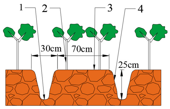
Figure 3.
Schematic diagram of ridge-farming potatoes. 1. Ridge furrow; 2. Potato plant; 3. Plastic film; 4. Ridge table.
The integrated film-collecting device allows simultaneous harvesting and film collection, cutting labor and time costs while combining potato harvesting with residual film recycling. Installed at the front of the harvester frame, the film-collecting device is structured as shown in Figure 4.
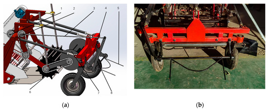
Figure 4.
Schematic diagram of the film-collecting device structure. 1. Hydraulic motor; 2. Movable crank; 3. Soil-shaking device connecting rod; 4. Film-stretching roller; 5. Soil-shaking device; 6. Soil-crushing roller; 7. Film-collecting roller; 8. Soil-shaking device swing rod. (a) Structure diagram, (b) Physical picture.
The film-collecting device comprises a soil-shaking device (mounted at the front of the frame), a connecting rod, a swing rod (for controlling the soil-shaking device), a hydraulic motor, a film-unfolding roller, a film-winding roller, and a transmission chain. During operation, the hydraulic motor rotates, and the chain drive controls the movable crank to move periodically, thereby driving the entire crank-connecting rod structure. Fork teeth are fitted at the front of the soil-shaking device. To ensure they can be inserted into the ground sufficiently to separate the film from the soil, they are designed to have a length of 350 mm. When the soil-shaking device inserts the fork teeth into the ground, it swings up and down continuously to dig out soil-covered residual film and separate it from weed stems. The film-unfolding roller, a flexible steel roller mounted on the frame behind the soil-shaking device, stretches and flattens the plastic film after impurity separation, guides its flow, and prevents it from winding around the frame. The film-winding roller is equipped with circular steel plates 380 mm in diameter at both ends, with a support shaft and four film-winding rods (15 mm in diameter) in the middle. These rods are evenly and symmetrically distributed on a 160 mm diameter circle. Their rough surface helps fix residual film to the roller. The four rods stretch the film during winding to generate tension, keeping it tight and prevent loosening or falling off. The structure featuring a thick end and a thin middle effectively prevents residual film from slipping off to both sides while winding. The film-winding roller receives power from the soil-crushing roller’s movement. When the soil-crushing roller rotates on the ground, it drives the film-winding roller via chain transmission. The gear ratio between them is 1:1, ensuring that the rotation speed of the film-winding roller matches the machine’s forward speed.
The residual film collection process is illustrated in Figure 5. The arrows indicate the flow direction of residual film, and points A, B, C, and D represent four position points with fixed relative positions to the harvester. In Figure 5a, the surface residual film prior to collection is covered by potato vines and soil. As the harvester moves forward, the soil-shaking device inserts into the ground at a certain angle. Driven by the crank–rocker mechanism, it tilts up and down on the soil surface. At point A, it pulls the residual film out of the compacted soil, separating surface soil and weed stems from the film. As the machine advances, it enters the state depicted in Figure 5b. The residual film reaches point B and passes through the film-unfolding roller. This roller not only initially crushes large surface soil clumps but also flattens the irregularly moving residual film after soil shaking, preventing the accumulation of film, soil, and vines from winding around the machine. When the residual film is transported backward to point C (Figure 5c,d), it passes through and wraps around the soil-crushing roller (which is in direct contact with the ground). The soil-crushing roller, equipped with steel beams of alternating protrusion heights, crushes the soil and catches the flattened residual film from the film-unfolding roller, rolling it up clockwise. As the subsequent residual film moves upward with the soil-crushing roller (Figure 5e,f), it reaches point D. Here, one end of the film contacts the film-winding roller and is rolled up for collection, thus completing the process.
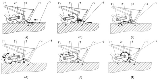
Figure 5.
Schematic diagram of residual film movement and collection process. 1. Soil-crushing roller; 2. Film-winding roller; 3. Film-flattening roller; 4. Soil-shaking device; 5. Residual film. (a) Residual film disturbance. (b) Residual film flattening. (c) Residual film movement. (d) Residual film conveyed by soil-crushing roller. (e) Residual film entering film-winding roller. (f) Film winding by film-collecting roller.
2.2.2. Potato Digging Equipment
During harvesting, the digging shovel breaks the surface soil and guides the soil–potato mixture. Optimizing the anti-adhesion, desorption, and soil-crushing performance of the front harvesting device is crucial for reducing digging resistance and improving potato–soil separation efficiency [22]. To achieve better soil penetration and crushing, the soil penetration shovel is designed as shown in Figure 6. To ensure the potato–soil mixture flows smoothly to the primary separation device, the shovel adopts a two-stage split design with a trapezoidal surface, divided into two halves. A movable stone guard is installed at the shovel tail, forming an overall two-stage planar composite structure.
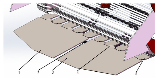
Figure 6.
Schematic diagram of the structure of the excavation shovel. 1. Left shovel surface; 2. Shovel surface connecting shaft; 3. Right shovel surface; 4. Connecting shaft of the stone guard grid; 5. Stone guard grid.
It can be seen from Figure 7 that the digging shovel is a split-type two-stage planar composite structure composed of two planes, AB and BC. Through two groups of different shovel surface angles (α1, α2), it realizes processes such as low-resistance soil penetration, high-performance soil crushing, and excavated material transportation of the excavator. Depending on the excavator movement conditions, the following equation is derived:
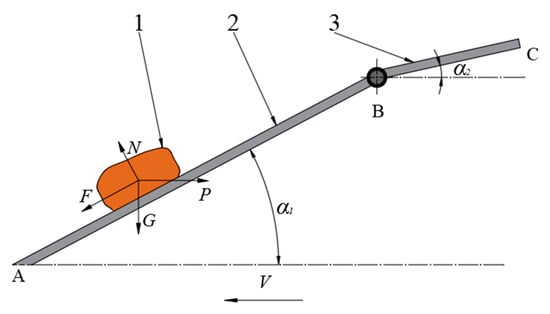
Figure 7.
Schematic diagram of the force on the excavation object and the shovel surface of the excavator. 1. Potato; 2. Shovel surface; 3. Stone guard grid.
P is the force required for the digging shovel to lift and convey potatoes, N; G is the gravitational force acting on the potato–soil mixture on the shovel surface, N; N is the reaction force of the digging shovel on the potato–soil mixture, N; F is the frictional force of the potato–soil mixture on the shovel surface, N; μ1 is the friction coefficient between the potato–soil mixture and the digging shovel—after consulting the literature, the value here is 0.45; α is the shovel surface angles (either α1 or α2 can be adopted), Deg.
The value of angle α can be derived from Formula (1), as shown in Formula (2) below.
Selecting an appropriate shovel surface inclination angle α ensures that the shovel cuts through soil ridges and smoothly conveys the potato–soil mixture to the rear [23]. A smaller angle improves soil penetration but prolongs the residence time of soil and potatoes on the shovel surface, leading to soil blockage. A larger angle enhances soil crushing performance yet increases shovel surface resistance, impairing soil penetration. The relevant literature indicates that when the shovel surface inclination angle ranges from 10° to 20°, the traction resistance is relatively low and the soil crushing effect is favorable [24]. The designed shovel surface is welded to the connecting frame of the digging shovel, which is connected to the harvester frame via a rotating shaft. Prior to operation, the soil penetration angle can be adjusted by changing the angle of the connecting frame, and it is fixed at 20° under normal working conditions.
The shovel surface adopts a trapezoidal design and penetrates the soil through sliding shear. The 160° included angle of the shovel edge contributes to enhancing soil penetration capability. It can also guide weed stems and stones in contact with the inclined surface, thereby avoiding blockage of the shovel edge and reducing wear. The total width of the left and right half-shovels is adjusted to 900 mm, with a thickness of 10 mm. The shovel surface is maintained as smooth and flat as possible to reduce soil adhesion, facilitate the flow of the potato–soil mixture, and minimize potato damage. A stone guard is installed at the tail of the shovel, comprising a grid plate and connecting pins, and is connected to the shovel surface via pins. There is a certain gap between the grid bars. Each grid bar can rotate at a certain angle around the connecting pin at the tail of the shovel. When encountering stones during harvesting, the stone guard can rotate around the connecting pin to guide the stones out of the harvesting screen and effectively push away easily agglomerated sticky soil clods to prevent them from blocking the gaps between the grid bars. The two-stage split structure and trapezoidal surface are conducive to the flow of sticky soil, minimizing blockages. Selecting an appropriate grid bar gap prevents potato leakage while enabling small sticky soil clods to pass through smoothly, reducing operation resistance. The stone guard is designed with 10 grid bars, each 100 mm in length, 60 mm in width, and 30 mm in spacing, and all are independent structures.
2.3. Conveying and Separating Device
Considering the existence of potato–soil mixture, to reduce potato damage and improve the potato impurity removal rate, the conveying and separation system is mainly composed of two parts, including a conveying and separation device and a secondary conveying and separation device. The conveying and separating devices are shown in Figure 8, below.
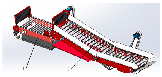
Figure 8.
Schematic diagram of conveying separation structure. 1. Secondary conveying and separation device; 2. Primary conveying and separation device; 3. Soil penetration shovel.
2.3.1. Primary Conveying and Separating Device
The potato–soil separation component is the most critical part of the harvesting process, directly affecting the final harvest effect. In the heavy clay soils of hilly and mountainous areas, the soil exhibits high viscosity, adhering strongly to potatoes and equipment, easily causing blockages. Meanwhile, the undulating terrain increases the difficulty of stably conveying materials. The primary separation conveyor belt requires an extended working distance to achieve the preliminary separation of the potato–soil mixture. When the potato–soil mixture is conveyed by the primary separation device, the separation screen surface separates soil clods and impurities with a diameter smaller than the gap between the rods. It also crushes potato–soil aggregates and large soil clods. This is especially crucial for cohesive, heavy soils that tend to form hard clods.
The elevating separation device adopts a rod-type elevating separator. The belt–rod elevator uses a belt as the medium to connect the rods. The rods are installed on the belt to form a conveyor belt. The belt–rod elevator has a large conveying area, suitable for conveying large quantities of materials. In heavy clay soil environments, its stable operation helps avoid material accumulation caused by sudden changes in soil viscosity. Furthermore, as a mature technology, the belt–rod type operates stably and inflicts minimal mechanical damage on potatoes, which is why it is selected as the main conveying and separation device [25].
Figure 9 is a three-dimensional schematic diagram of the primary separation device for potato harvesting. In the figure, (1) is the main drive shaft. It is powered by a hydraulic motor and driven to operate through chain transmission, ensuring sufficient power to cope with the increased resistance caused by heavy clay soils. (2) is the auxiliary drive shaft. It cooperates with the main drive shaft to provide rotational power for the separation and conveying mechanism, enhancing the operational stability on undulating terrain. (3) is the rod, which is used to filter impurities such as soil and weeds from potatoes and break up large soil clods through collision. (4) is the shaking device, composed of two cams. It realizes the shaking effect of the separation screen surface through cam rotation, which can effectively reduce soil adhesion on the screen surface and prevent blockages under heavy clay soil conditions.
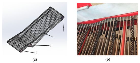
Figure 9.
Primary detachable rod lifter. 1. Main drive shaft; 2. Auxiliary drive shaft; 3. Rods; 4. Shaking device. (a) Structural diagram. (b) Physical picture.
The separating screen, a key component for potato–soil separation, adopts an all-straight-bar planar conveying surface. It lacks a “guiding” effect, causing potato tubers to slip, shift at chain connections or during speed changes, and even become stuck between bars—thereby leading to blockages that hinder conveying and separation. In soils with strong adhesion and high moisture content, straight bars are prone to “compacted” soil buildup, requiring frequent shutdowns for cleaning. Thus, screen surface design must address both the need for variable inclination angles to reduce slippage and the prevention of soil compaction in straight-bar transmission. As shown in Figure 10, the separating screen is designed with 4 concave bars and 1 rubber-toothed straight bar arranged alternately. The groove between curved and straight bars creates a height drop, reducing blockages and soil accumulation.
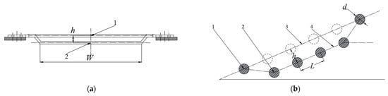
Figure 10.
Schematic diagram of the structure of the lifting chain bar. 1. Straight rod; 2. Curved rod; 3. Straight rod plane; 4. Curved rod plane. (a) Front view. (b) Sectional view.
As shown in Figure 10, if the screen surface bars are all configured as straight bars, six bars form a screening plane 3, and the gap area of this plane is
S1, the gap area of the screening plane (plane 3) with all straight bars; L, rod spacing, 45 mm; W, working width of the elevator chain rod, 1000 mm. When the rods are arranged in an alternating pattern of straight and curved rods, the total gap area S2 between six rods in the screening plane is shown in the figure as:
In the formula above, h is the groove depth of the curved rods in the elevator chain, 20 mm; d is diameter of the rod, 10 mm. By combining Formulas (3) and (4) and substituting the relevant data, the following formula can be obtained:
It can be inferred from Formula (5) that compared with the all-straight rod configuration, the straight–bent rod configuration has an increase in the screening area. When the potato soil transitions to the sieve surface concave rod, the sieve surface inclination changes, and the potato soil in this place is stressed and analyzed.
The force equilibrium equations are established as follows:
N1 is the support force of the curved rod on the potato tuber; N2 is the support force of the straight rod on the potato tuber; γ1 is the angle between the support force N1 and the horizontal direction; γ2 is the angle between the support force N2 and the horizontal direction; G is the self-gravity of the potato–soil mixture. To prevent backflow of the potato–soil mixture, it needs to have an acceleration moving rearward, that is, the resultant force in the horizontal direction should be:
To improve the conveying efficiency of the potato–soil mixture, the horizontal resultant force Nx can be appropriately increased. It can be seen from Formula (8) that the resultant force Nx increases when γ1 increases and γ2 decreases. By comparing Figure 11a,b, it is found that when the working inclination angle β of the elevator chain of the potato harvester remains unchanged, the elevator chain with the alternating arrangement of straight and curved rods has a larger γ1 and a smaller γ2 than that with the all-straight-rod arrangement. As a result, the resultant horizontal force on potatoes is greater, which can effectively improve conveying efficiency and reduce the backflow of potatoes. Similarly, in the design of the elevator chain with alternating straight and curved rods, the conveying efficiency of potato soil can also be improved by appropriately adjusting the groove depth of the curved rods to change the sizes of angles γ1 and γ2.
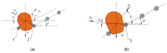
Figure 11.
Schematic diagram of the force on the potato rod. 1. Straight rod bar; 2. Curved rod bar. (a) Schematic diagram of alternating force on straight–curved rods; (b) Schematic diagram of force on all straight rods.
The vibration wheel is designed with a cam structure. As shown in Figure 12, R is the radius of the vibration wheel, and L is the eccentric distance of the vibration wheel. The two vibration wheels are symmetrically installed on the inner side of the frame. An electric motor drives the shaft of the vibration wheel, and the cams come into contact with the screen surface to apply high-frequency low-amplitude vibrations to the separation screen, causing the screen surface to exhibit wavy motion.
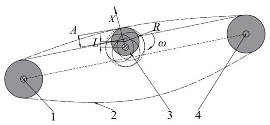
Figure 12.
Schematic diagram of the elevator chain operation. 1. Driving and driven wheels; 2. Elevator chain; 3. Vibration wheel; 4. Drive wheel.
The vibrating cam is driven by a brushless motor, and the elevator chain can generate vibration through periodic rotation. The displacement–time equation can be obtained by using the variation of the elevator chain’s motion amplitude over time. By taking the first and second derivatives of the displacement equation, the following formulas can be derived.
X, displacement of the elevator chain in the direction perpendicular to the chain surface, m; A, amplitude generated by the elevator chain under the vibration of the vibration wheel, m; ω, the angular velocity of the elevator chain vibration, rad/s; v, velocity of the elevator chain in the direction perpendicular to the chain surface, m/s; a, acceleration of the elevator chain in the direction perpendicular to the chain surface, m/s2; f, the rotation frequency of the vibrating wheel, which is numerically equal to the vibration frequency of the elevator chain, Hz.
When the elevator chain vibration reaches the maximum amplitude, the potato–soil mixture will be thrown up. The analysis of its force and velocity is shown in Figure 13:
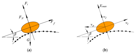
Figure 13.
Force and velocity analysis diagrams of the potato throwing process. (a) Force analysis diagram; (b) Velocity analysis diagram.
According to the force balance process of potatoes, there is Formula (10) when the potato is just about to leave the conveyor belt.
In Formula (10), the following apply: m, mass of the potato–soil mixture, kg; β, working inclination angle of the elevator chain; g, gravitational acceleration, m/s2; Fi, inertial force acting on the potato vertically upward along the chain surface, N. In Figure 13a, FN is the supporting force exerted by the elevator chain on the potato, and Ff is the friction force exerted by the elevator chain on the potato. Since the moment when the potato is just about to leave the elevator chain is considered here, both FN and Ff are 0.
As shown in Figure 13b, a kinematic analysis of the potato is conducted. When the potato has just left the elevator chain, the following Formula (11) is derived based on the vertical upward throwing formula:
In Formula (11), Xmax is the maximum height to which the potato is thrown when it detaches from the elevator chain in the direction perpendicular to the chain surface; v2 is the component velocity of the potato in the direction perpendicular to the chain surface, m/s; and vp is the forward speed of the harvester, m/s. In Figure 13b, v1 is the linear velocity of the elevator chain, which is perpendicular to v2. By substituting the acceleration a from Formula (9) into Formula (10), Formula (12) can be obtained.
From the calculation process of velocity v in Formula (9), it can be inferred that when v reaches its maximum value, sin(2πft) takes the value of 1 and, thus, the maximum value of v2 can be obtained through simplification:
From the relevant literature [26], it is known that to reduce mechanical damage to potatoes caused by their being thrown on the elevator chain, the maximum value of Xmax is set to 0.3 m, the maximum operating speed of potato harvesting vp is 3 m/s, and the inclination angle of the elevator chain β is 30 degrees. Substituting these values into Formulas (11)–(13), it can be established that:
The amplitude A and frequency f of the vibrating wheel influence the height to which potatoes are thrown upward on the elevator chain. When the amplitude and frequency form a certain relationship, they can enhance the scattering effect of the potato–soil mixture and reduce potato damage. From [27], it is known that the vibration frequency of the harvester’s separation screen generally ranges from 3 to 8 Hz, with a maximum amplitude not exceeding 0.06 m. Combined with Formula (14), the vibration amplitude A of the elevator chain is finally determined to be 0.06 m, and the frequency f to be 4 Hz. The radius of the vibrating cam is set to 0.14 m, and the eccentricity to 0.06 m, so that each full rotation can generate one vibration for the elevator chain.
Since the separation screen in the primary separation process can only separate impurities with a diameter smaller than the gap between the screen rods, longer potato stems, weeds, and the like cannot be thoroughly separated. Therefore, a separation curtain that slows down the falling of potatoes is installed at the end of the primary separation screen. The separation curtain can adjust the postures of potatoes, weeds, and stems, and reduce damage to potatoes. Considering that the separation curtain needs to have good elasticity and wear resistance while reducing production costs, it is made of rubber [28]. A stem and leaf deflector rod is installed at the lower end of the rubber separation curtain, as shown in Figure 14.
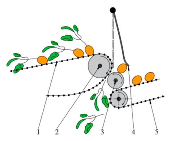
Figure 14.
Schematic diagram of the stem–leaf deflector rod operation. 1. Primary elevator chain; 2. Main drive shaft of the elevating chain; 3. Stem–leaf deflector rod; 4. Rubber separation curtain; 5. Secondary elevator chain.
During operation, the potato–soil mixture with high density and heavy quality is pushed by the primary separation screen to be discharged from the bottom of the rubber separation curtain 4 and falls onto the secondary separation device. Weeds with low density and large volume are blocked when passing through the screen surface. Driven continuously by the elevating chain, more weed stems are squeezed into the gap between the elevating chain and the rubber curtain. As the rubber teeth on the rods continuously toggle downward around the elevating chain drive shaft (2), the weed stems are forced to flow into the gap between the elevating chain drive shaft (2) and the stem and leaf deflector rod (3). The stem and leaf deflector rod and the main elevating drive shaft rotate at the same speed but in opposite directions. Here, the weed stems are clamped and carried out of the primary separation device under the action of the upper and lower rollers rotating in opposite directions, thus achieving complete separation of stems and weeds.
2.3.2. Secondary Conveying and Separating Device
After primary separation, the potato–soil mixture is free of small-diameter, easily crushable soil clumps and loose soil, with only large unbroken soil clumps and soil adhering to the potato surface remaining. Thus, a secondary separation mechanism is designed to further separate the potato–soil mixture. In addition, an artificial sorting platform is installed on the frame. It enables manual intervention to remove impurities like stones that are similar in size to potatoes.
During secondary separation, the elevating chain plays a role in both transportation and secondary separation. The sorting platform, on the other hand, relies on manual sorting to remove unbroken soil clumps and stones. The secondary potato–soil separation device adopts a chain–rod structure. Figure 15 below is a schematic diagram of the secondary separation elevating device for potatoes. It mainly consists of a chain–rod conveyor belt, a soil transfer belt, a buffer curtain, and other components.
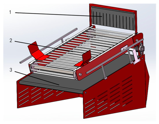
Figure 15.
Schematic diagram of the structure of the secondary potato–soil separation device. 1. Buffer curtain; 2. Chain–rod conveyor belt; 3. Soil transfer belt.
The process of potatoes being transported from the secondary elevator chain to the scraper conveyor belt is shown in Figure 16.
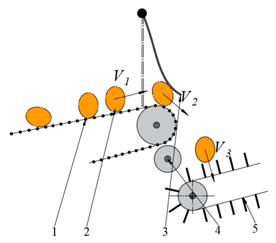
Figure 16.
Schematic diagram of the potato movement process. 1. Secondary elevator chain; 2. Potatoes; 3. Buffer curtain; 4. Stem–leaf deflector rod; 5. Scraper conveyor belt.
A rubber buffer curtain is also designed at the highest point of the secondary elevator chain. When potatoes are conveyed to the highest point of the elevator chain, they collide with the rubber buffer curtain. Before meeting the buffer curtain, potatoes are conveyed upward along the transmission chain at the speed of V1. When they reach the rubber buffer curtain 3 and collide with it, the kinetic energy of the potatoes is transferred to the rubber curtain. The rubber curtain absorbs the energy and deforms, and the kinetic energy of the potatoes decreases accordingly. At this point, the speed V2 is much lower than V1. After passing through the rubber curtain, potatoes make an oblique projectile motion in the direction of V2. Under the action of gravity, they hit the scraper conveyor belt 5 at a speed of V3. The surface of the scraper conveyor belt is made of rubber, which helps reduce collision damage to potatoes.
Four stem–leaf deflecting rods are also installed between the secondary transmission chain and the scraper conveyor belt. Their function is similar to that of the stem–leaf deflecting rods in the primary elevator chain, enabling the further removal of residual weeds and stems. The crushed soil manually falls onto the conveyor soil belt through the gaps in the secondary elevator chain. To prevent soil clumps from falling onto the harvester frame, the width of the soil conveyor belt must be significantly larger than that of the secondary separation elevator chain. The width of the elevator chain is 1000 mm, and that of the soil conveyor belt is 1350 mm, which conveys the crushed soil downward to the ground surface.
2.4. Intelligent Potato Collection Device
As shown in Figure 17, below, the potato collection cabin is installed at the rear of the harvester to receive potatoes separated through the primary and secondary separation processes, and it is loaded onto a vehicle after being filled. The potato collection box is mainly composed of a scraper conveyor belt, drive motor, potato collection box body, box pallet, hydraulic cylinder, and other components.
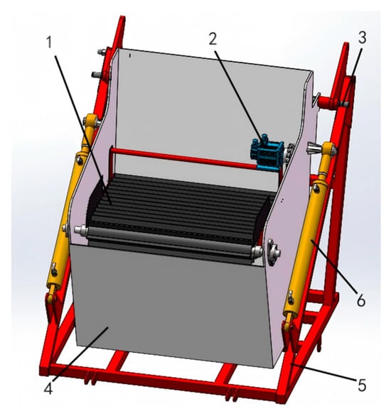
Figure 17.
Structural diagram of the potato collection box. 1. Scraper conveyor belt; 2. Drive motor; 3. Rotation shaft of potato collection box; 4. Potato collection box body; 5. Box pallet; 6. Hydraulic cylinder.
The scraper conveyor belt uses a rubber belt, and the conveyor belt design consists of a driven wheel, a driving wheel, a conveyor belt, and a bracket rotating shaft. Considering comprehensively such parameters as the conveying speed of the conveyor belt, the size of the scraper, and the conveying speed of the scraper conveyor belt of the designed harvester, the designed potato conveying capacity C of the potato collecting box can be obtained by combining Formulas (15) and (16).
Va, conveyor belt conveying line speed, 1.2 m/s; Sx, cross-sectional area filled with materials on the scraper elevator conveyor belt, m2; k, filling coefficient of the conveyed material, taken as 0.60; ρ, density of the material, taken as 105 kg/m3; a, average nominal diameter of potato tubers, taken as 0.10 m; b, width of the conveyor belt, taken as 0.89 m. By substituting the relevant data above, the designed potato transportation capacity C can be calculated to be approximately 24,200 kg/h.
The potato pieces are thrown off the scraper conveyor belt. During their movement, they are only subject to gravity, performing a uniformly accelerated curvilinear motion. The trajectory of the potato pieces can be derived from the projectile motion equations and the motion parameters of the potato pieces. The potatoes and the scraper conveyor belt are relatively stationary, with the same direction of movement velocity. After the potato pieces break away from the conveyor belt, they are only affected by gravity, which has a constant magnitude and a downward direction, and are not subject to any force in the horizontal direction. They perform a downward projectile motion from the highest point until they fall to the bottom of the container, as shown in Figure 18.
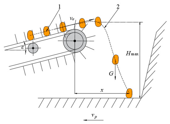
Figure 18.
Schematic diagram of the potato collection process. 1. Potato; 2. Potato movement trajectory.
The displacement motion equation is as follows:
It can be inferred from the test conditions that in Formulas (17) and (18), the following apply: x, horizontal movement displacement of potato tubers, mm; Hmax, the distance from the highest point of the potato to the bottom of the box, mm; g, gravitational acceleration, m/s2; t, fall time of potato tubers, s; vp, forward speed of the harvester, 0.5 m/s; va, conveyor belt conveying line speed, 1.2 m/s; ε, inclination angle of scraper conveyor belt. When x is at its maximum, the value of ε is 0 degrees.
Potato tubers are prone to mechanical damage when subjected to impacts and collisions [29]. The three factors that have the most significant impact on the area and depth of potato damage are the drop height, potato mass, and collision material [30]. To reduce the collision damage of potatoes, a layer of sponge pad covers the steel plate at the bottom of the potato collecting box, aiming to achieve the goal by changing the direct collision material of potatoes. Through data consultation, to control the damage caused by the drop height, the maximum distance (Hmax) from the highest point of potato movement to the bottom of the potato collection box must not exceed 800 mm. To prevent potatoes from hitting the rear wall of the potato collection box when being thrown, the known design parameters are substituted into Formula (16), and the maximum value of x is 280 mm. Based on this, combined with the length of the conveyor belt, the bottom width of the potato collection box is designed to be 750 mm, the minimum height of the side is 980 mm, the maximum height is 1350 mm, and the fixed installation position of the left rotating shaft of the scraper conveyor belt is 700 mm away from the bottom of the box.
If the unloading position of the fixed conveyor belt remains unchanged, it will cause uneven accumulation in the potato collecting box, resulting in the actual loading capacity of the potato collecting box being lower than the designed capacity and reducing the operating efficiency. During the normal potato loading process, operators need to frequently observe the status of the potato collecting box and adjust the position of the conveyor belt and the potato dropping height. Otherwise, uneven accumulation may occur in the potato collecting box, leading to the actual loading capacity being lower than the designed capacity and a decrease in operating efficiency. It may also cause potatoes to spill over or become damaged due to delayed response. Therefore, the scraper conveyor belt is designed to be of the height-adaptive adjustment type, which can change the inclination angle of the conveyor belt to adjust the dropping height of potatoes according to the monitoring feedback signal of the accumulation height of potatoes in the potato collecting box.
The detection device of the designed height-adaptive potato collection box mainly includes a controller, a height detection device, and an execution module. The height detection device is installed on both sides of the conveyor belt, and the sensor used is a photoelectric sensor. The working principle of height detection is shown in Figure 19.
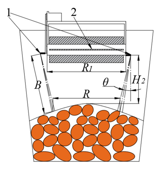
Figure 19.
Schematic diagram of photoelectric sensor detection. 1. Photoelectric sensor; 2. Scraper conveyor belt.
Since the positions where potatoes fall from the conveyor belt basically follow a normal distribution, the left–right offset of the center line of the potato pile is small. Considering factors such as the falling height of potatoes and the stacking height of potatoes, the analytical formulas for the height detection process are as follows:
H2, the height from the potato dropping point on the conveyor belt to the potato pile; R1, the sensor spacing; B, the sensor detection set distance; R, spacing between the sensor light source center line and the monitoring point.
Due to the ridge cultivation of potatoes, the left and right offset of the center line of the potato pile is small, and the distribution of potato falling positions basically conforms to the characteristics of normal distribution. Therefore, after considering the material distribution characteristics, the detection distance R of the two photoelectric sensors is set to 600 mm. According to Formula (19), the height H2 from the potato dropping point on the conveyor belt to the potato pile can be obtained.
To ensure the complete collection of potatoes, it is necessary to control the potato dropping height. The execution module is an electric push rod for adjusting the inclination angle of the conveyor belt, installed as shown in Figure 20. One end is fixed inside the potato collection box, and the other end is fixed on the bottom bracket of the scraper conveyor belt. When the electric push rod operates, the scraper conveyor belt can rotate around a fixed shaft inside the potato collection box. The PLC controller can accurately sense the feed length of the actuator, analyze and process the collected status information, and issue instructions according to a predefined control process to precisely drive the electric push rod to act.
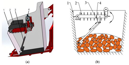
Figure 20.
Schematic diagram of the adaptive adjustment device for potato dropping height of the potato collecting box. 1. Potato collection box; 2. Scraper conveyor belt; 3. Electric push rod for conveyor belt inclination adjustment; 4. Photoelectric sensor: (a) 3D schematic diagram, (b) 2D simplified structural diagram.
The main logic flow of the height-adaptive potato collection device control system is as follows: When the system is started, it initializes the parameters. The system then enters a self-checking state, during which the actuators automatically reset, and the electric push rod stroke is set to the minimum feed state. The system utilizes signals from photoelectric sensors to obtain the height difference between the end of the scraper conveyor belt and the potato surface and determines whether to control the electric push rod of the actuator. As the potato stacking height increases, the electric push rod of the actuator increases the amount of feed to make space for potato stacking. When it detects that the height difference between the potato surface and the scraper conveyor belt is excessively large, the push rod retracts to avoid potato damage caused by an excessive height difference. After completing the potato loading, the potato unloading mechanism unloads the full potato collection box onto the field. The control flow chart is shown in Figure 21.
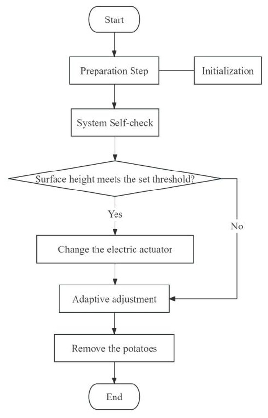
Figure 21.
Control logic flow chart.
To enable the potato collection box to achieve automatic machine unloading, hydraulic cylinders are installed on both the left and right sides of the box to facilitate the loading and unloading of potatoes.
As shown in Figure 22a, during the potato collection process, the hydraulic cylinders are not in operation, and the potato collection box is in a horizontal position, connected to the box bracket via a rotating shaft. When the potato collection box is full or contains a certain number of potatoes, as shown in Figure 22b, the driver induces the two hydraulic cylinders to lift, causing the potato collection box to flip around the rotating shaft, thus realizing the unloading operation of the potato harvester.
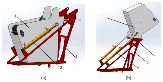
Figure 22.
Schematic diagram of automatic unloading of potato collection box. 1. Potato collection box; 2. Hydraulic cylinder; 3. Rotating shaft of the potato collection box; 4. Box bracket: (a) Potato box horizontal; (b) Potato box lifted.
3. Results and Discussion
3.1. Test Site and Methods
In November 2024, a field operation performance test of potato harvesters was conducted in Huangzhong County, Xining City, Qinghai Province. This area is a typical northwest mountainous and hilly environment, with an altitude ranging from 2225 m to 4488 m and sloping land accounting for 60%. The potato planting method was double-row film mulching. One week before harvest, the potato haulms were removed, along with weeds and stems.
According to the national industry standard, “NY/T 648-2017 Technical Specification for Quality Evaluation of Potato Harvesters” [31], the measurement area for the field harvesting test of self-propelled potato harvesters was 30 m in length, with 10 m stable zones at both ends and a width of 30 m. During the test, two round-trip strokes were measured. For each stroke, three plots were randomly selected, with each plot being 3 m long and the width being the working width of the machine. The test mainly investigated the main performance of the potato harvester. The driving speed of the test prototype was set at 0.5 m/s, the linear speed of the primary conveying and separating device was 0.9 m/s, and the linear speed of the secondary conveying and separating device was 1.2 m/s.
3.2. Measurement Parameters and Methods
The performance measurement parameters of the potato harvester include potato harvesting quality parameters and residual film recycling quality parameters. The potato harvesting quality parameters include potato loss rate, damaged potato rate, impurity content rate, and skin-breaking rate. The measurement methods for each index refer to “NY/T 648-2017 Technical Specification for Quality Evaluation of Potato Harvesters”. The residual film recycling quality parameter is the residual film cleaning rate, and the measurement method refers to “GB/T 25412-2021 Residual Film Field Recycling Machine” [32].
3.2.1. Potato Harvesting Quality
- (1)
- Loss rate. After the prototype operates, collect and weigh the potato tubers (Q1) that are dug out by the prototype but not picked up within the measurement area, and manually find and weigh the residual potato tubers (Q2) that are not dug out by the prototype. Weigh the mass of potato tubers (Q4) in the potato collection box. Define the sum of the missed dug potato quantity and the missed picked potato quantity of the potato harvester as the lost potato quantity and use Formula (20) to calculate the potato harvesting loss rate.
In the formula above, L1 is the loss rate, in percentage (%) form; Q is the total potato mass, in kilograms (kg), where Q = Q1 + Q2 + Q4; Q1 is the mass of missed picked potatoes, in kilograms (kg); Q2 is the mass of missed dug potatoes, in kilograms (kg); and Q4 is the mass of harvested potatoes, in kilograms (kg).
- (2)
- Damaged potato rate. Collect all damaged potatoes from the missed picked potatoes, missed dug potatoes, and harvested potatoes, and weighing their mass (Q3). The damaged potato rate in potato harvesting is calculated using Formula (21).
In the formula above, L2 is the damaged potato rate, in percentage (%) form; Q3 is the mass of damaged potatoes, in kilograms (kg).
- (3)
- Impurity content rate. After the prototype operates, collect impurities (soil clods, potato vines, broken film) in the potato box and weigh their mass (Q5). The impurity content rate in potato harvesting is calculated using Formula (22).
In the formula above, L3 is the impurity content rate, in percentage (%) form; Q5 is the mass of impurities, in kilograms (kg).
- (4)
- Skin-breaking rate. Collect all skin-broken potatoes from the missed picked potatoes, missed dug potatoes, and harvested potatoes, and weigh their mass (Q6). The skin-breaking rate in potato harvesting is calculated using Formula (23).
In the formula above, L4 is the skin-breaking rate, in percentage (%) form; Q6 is the mass of skin-broken potatoes, in kilograms (kg).
3.2.2. Residual Film Recycling Quality
In accordance with the test standard requirements, five measurement points were selected before and after the operation, with each point being 5 m long and the width equal to the ridge width. Before the operation, the residual film on the surface layer (ground surface and soil depth of 0–100 mm) at the five measurement points was manually removed. After the operation, the residual film left on the surface layer at another five measurement points was picked up, and after removing dust and moisture, their weights were measured. The residual film cleaning rate for each measurement point was calculated using the following formula:
In the formula above, J is the residual film cleaning rate (%); W is the mass of residual film in the surface layer or deep layer after operation (kg); and W0 is the mass of residual film in the surface layer or deep layer before operation (kg).
3.3. Test Results and Analysis
The performance test of the potato harvester was carried out according to the standard test method, and the results of the field performance test are shown in Table 2.
Table 2.
Test results for potato harvester.
The test results show that all indicators of the harvesting quality and residual film recovery quality of the designed potato harvester can meet the requirements of the national standards. The harvester has good adaptability in northwestern hilly areas such as Xining City, Qinghai Province, and can meet the potato harvesting needs in these areas. When compared with other related designs of potato harvesters and integrated potato harvesting and residual film-recovering machines, the potato harvester designed in this study achieves better comprehensive performance in terms of visible potato rate, damaged potato rate, and residual film recovery rate. While ensuring a high residual film recovery rate, it features a lower potato loss rate and damaged potato rate, which can effectively meet the harvesting needs of mulched potato planting in hilly and mountainous areas. Moreover, it has shown good performance on the experimental site.
A comparison of the test results for this machine with similar studies reveals the following: the 1FMX-80 potato residual film recovery machine designed by Zhang et al. [33] has a loss rate of 4.4%, a damaged potato rate of 4.2%, and a residual film recovery rate of 86%; the residual film recovery-type full-film-covered ridge-sown potato digger designed by Sun et al. [34] has a loss rate of 2.6%, a damaged potato rate of 1.3%, and a residual film recovery rate of 87.5%. It was found that the tested machine still maintains good performance in terms of loss rate, damaged potato rate, and residual film recovery rate under heavy soil conditions, and its adaptability and operational effects at the experimental site are worthy of recognition.
A comparison with harvesters without relevant film-collecting mechanisms shows the following: The remote-controlled self-propelled harvester suitable for hilly and mountainous areas designed by Jia et al. [35] has a loss rate of 1.6%, a damage rate of 1.1%, and an impurity rate of 2.3%; and the multi-stage separation potato harvester designed by Issa et al. [36] has a loss rate of 1.2%, a damage rate of 1.43%, and a skin-breaking rate of 1.37%. It was found that even in the special environment with residual film and heavy soil, the tested machine still performs well in terms of damage rate, skin-breaking rate, and impurity rate, which further confirms that it can stably exert its operational performance at the experimental site with ideal test results.
4. Conclusions
This study explores key challenges in mechanizing the harvesting of film-covered potatoes in hilly and mountainous areas. Given the industry pain points in these regions—such as incomplete residual film collection by existing equipment, poor potato–soil separation due to sticky soil, high impurity levels, and high tuber damage rates—we designed a crawler-type self-propelled potato combine harvester with integrated functions. It aims to address technical shortcomings in efficient, low-damage harvesting of film-covered potatoes in hilly and mountainous areas.
In the common sticky or high-moisture soils of hilly regions, potato–soil separation efficiency is low with high impurities. Existing harvesters lack effective residual film recovery, and large harvesters have poor maneuverability in small plots and sloped fields. To achieve the goal of this study, the design focuses on integrating four core functions: residual film collection, potato digging, multi-stage soil separation, and intelligent potato collection. The integrated film-collecting device uses a crank-connecting rod-driven soil-shaking mechanism and a flexible film-rolling system, achieving a residual film cleaning rate of 89.6% for efficient recovery. Unlike traditional passive film-collecting structures, its active soil-shaking time (350 mm) effectively separates residual film from soil and vines. The film-rolling roller, designed to be “thick at both ends and thin in the middle”, prevents film loosening during collection, outperforming existing equipment with lower residual film recovery rates. The two-stage split digging shovel balances soil penetration and resistance reduction, resolving the conflict in hilly soils between shallow digging (high loss rate) and deep digging (high resistance). The primary and secondary conveying separation devices adopt alternating straight and curved rods with high-frequency, low-amplitude vibration, enhancing soil fragmentation, reducing tuber backflow, and improving separation efficiency, lowering impurity content to 2.8%—lower than similar small harvesters. The height-adaptive scraper conveyor belt in the potato collection box, controlled by photoelectric sensors and electric push rods, adjusts the dropping height in real time to avoid collision damage. Combined with a sponge-padded box bottom, this mechanism reduces the skin-breaking rate to 2.7% and the damage rate to 1.4%, outperforming most existing harvesters.
Moving forward, we will expand the harvester’s testing scope across different terrains and soil conditions in hilly and mountainous areas. Through multi-regional, multi-batch field operation verification, we will continuously optimize its performance parameters and enhance its adaptability to complex environments. Meanwhile, we will carry out demonstration applications, accumulate practical operation data, provide strong support for large-scale promotion of the equipment, and help improve the overall level of the mechanized harvesting of film-covered potatoes in hilly and mountainous areas.
Author Contributions
Conceptualization, H.F. and Q.Z.; methodology, H.F. and J.L. (Jinyu Li); software, J.L. (Jinyu Li) and Q.Z.; validation, H.F., Q.Z. and J.L. (Jinyu Li); formal analysis, J.L. (Jinyu Li) and J.Z.; investigation, J.L. (Jinyu Li), G.C., J.L. (Jialu Lu) and J.Z.; resources, H.F.; data curation, H.F.; writing—original draft preparation, J.L. (Jinyu Li) and J.L. (Jialu Lu); writing—review and editing, H.F. and Q.Z.; visualization, Q.Z.; supervision, Q.Z.; project administration, H.F.; funding acquisition, Q.Z. All authors have read and agreed to the published version of the manuscript.
Funding
This research was funded by the China Postdoctoral Science Foundation, grant number 2023M741433, the Research Foundation for Talented Scholars of Jiangsu University, grant number 22JDG041, the Priority Academic Program Development of Jiangsu Higher Education Institutions, grant number PAPD-2023-87, and the Key R&D Program of Shandong Province, grant number 2024TZXD058.
Institutional Review Board Statement
Not applicable.
Data Availability Statement
The data presented in this study are available within the article.
Conflicts of Interest
Author Guangsen Cheng was employed by the company Yucheng Yatai Machinery Manufacturing Co., Ltd. The remaining authors declare that the research was conducted in the absence of any commercial or financial relationships that could be construed as a potential conflict of interest.
References
- Ali, A.B.; Hong, L.; Elshaikh, N.A.; Basheer, A.K.; Yan, H.F. Impact of Center Pivot Sprinkler Speed and Water Regimes on Potato Crop Productivity. Int. J. Agric. Biol. 2016, 18, 1174–1180. [Google Scholar] [CrossRef]
- Mao, C.; Wu, J.; Zhang, X.Z.; Ma, F.P.; Cheng, Y. Improving the Solubility and Digestibility of Potato Protein with an Online Ultrasound-Assisted PH Shifting Treatment at Medium Temperature. Foods 2020, 9, 1908. [Google Scholar] [CrossRef]
- Tunio, M.H.; Gao, J.M.; Shaikh, S.A.; Imran, A.L.; Waqar, A.Q.; Solangi, K.A.; Farman, A.C. Potato Production in Aeroponics: An Emerging Food Growing System in Sustainable Agriculture for Food Security. Chil. J. Agric. Res. 2020, 1, 118–132. [Google Scholar] [CrossRef]
- Wu, J.; Mao, C.; Zhang, W.L.; Cheng, Y. Prediction and Identification of Antioxidant Peptides in Potato Protein Hydrolysate. J. Food Qual. 2020, 2020, 10. [Google Scholar] [CrossRef]
- Zhang, C.; Shi, X.M.; Yu, F.F.; Quan, Y. Preparation of Dummy Molecularly Imprinted Polymers Based on Dextran-Modified Magnetic Nanoparticles Fe3O4 for the Selective Detection of Acrylamide in Potato Chips. Food Chem. 2020, 317, 7. [Google Scholar] [CrossRef]
- Ngallina, C.; Spano, M.; Sobolev, A.P.; Esposito, C.; Santarcangelo, C.; Baldi, A.; Daglia, M.; Mannina, L. Characterization of Local Products for Their Industrial Use: The Case of Italian Potato Cultivars Analyzed by Untargeted and Targeted Methodologies. Foods 2020, 9, 1216. [Google Scholar] [CrossRef]
- Wu, B.G.; Guo, Y.T.; Wang, J.; Pan, Z.L.; Ma, H.L. Effect of Thickness on Non-Fried Potato Chips Subjected to Infrared Radiation Blanching and Drying. J. Food Eng. 2018, 237, 249–255. [Google Scholar] [CrossRef]
- Wu, B.G.; Wang, J.; Guo, Y.T.; Pan, Z.L.; Ma, H.L. Effects of Infrared Blanching and Dehydrating Pretreatment on Oil Content of Fried Potato Chips. J. Food Process. Preserv. 2018, 42, 7. [Google Scholar] [CrossRef]
- Lu, B.; Sun, J.; Yang, N.; Hang, Y.Y. Fluorescence Hyperspectral Image Technique Coupled with HSI Method to Predict Solanine Content of Potatoes. J. Food Process. Preserv. 2019, 43, 11. [Google Scholar] [CrossRef]
- Lu, K.; Xie, S.; Gai, X.; Ji, X. Design and Experiment of Toggle Lever-Type Potato Picker. Agriculture 2024, 14, 826. [Google Scholar] [CrossRef]
- Wang, K.F.; Zhao, Y.D.; Shi, S.B. Study on the Effect of Rhizosphere Topdressing of Film-Mulched Potatoes in High-Altitude Areas. Qinghai Agric. Technol. Ext. 2023, 3, 21–23. [Google Scholar] [CrossRef]
- Du, X.; Liu, J.; Zhao, Y.; Zhang, C.; Zhang, X.; Wang, Y. Design and Test of Discrete Element-Based Separation Roller Potato–Soil Separation Device. Agriculture 2024, 14, 1053. [Google Scholar] [CrossRef]
- Bunker Harvester SE 75-55 GRIMME Product. Available online: https://products.grimme.com/cn/p/se-75-55 (accessed on 29 May 2025).
- AVR Machinery. Available online: https://www.avr.be/en/node/41 (accessed on 29 May 2025).
- The Gold Standard of Potato Harvesting Equipment. Available online: https://www.doublelglobal.com/potato-harvester.php (accessed on 29 May 2025).
- Liu, C.C.; Wu, N.; Cheng, G.S.; Wu, F.; Gu, F.W.; Shi, L.L.; Wang, B. Design and Optimization of a Lightweight and Simple Self-Propelled Crawler Potato Combine Harvester. Agronomy 2025, 15, 65. [Google Scholar] [CrossRef]
- Yang, X.; Wu, Y.; Wang, L.; Liu, F.; Zhao, X.; Bai, H.; Dong, W.; Kong, X.; Hu, H.; Zhong, W. Design and Performance Test of 4UJ-180A Potato Picking and Bagging Machine. Agriculture 2024, 14, 454. [Google Scholar] [CrossRef]
- Zhang, X.; Liu, J.; Zhang, C.; Zhao, Y.; Du, X. Design and Experimentation of Small Potato Harvester for Heavy Soil in Hilly and Mountainous Areas. Agronomy 2024, 14, 2131. [Google Scholar] [CrossRef]
- Ma, Y.L.; Yang, S.M.; Li, M.Q.; Wang, Q.; Ke, Z.R. Design of an integrated machine for potato harvesting and residual film recycling in complex terrain. J. Hebei Univ. (Nat. Sci. Ed.) 2022, 42, 569–579. [Google Scholar] [CrossRef]
- Dai, F.; Zhao, W.Y.; Sun, W. Design and Experiment of a Potato Harvesting and Pneumatic-Assisted Residual Film Recycling Combined Operation Machine. Trans. Chin. Soc. Agric. Mach. 2017, 01, 64–72. [Google Scholar] [CrossRef]
- Chen, H. Effects of Cultivation Patterns on Potato Growth and Yield. Trop. Agric. Eng. 2024, 48, 100–103. [Google Scholar]
- Wang, H.C.; Zhao, W.Y.; Sun, W.; Meng, Y.R.; Gao, K.Z.; Shi, R.J. Design and experiment of a multi-mode steering, viscosity-reducing and soil-crushing potato combine harvester for dry farming areas in Northwest China. Trans. Chin. Soc. Agric. Mach. 2025, 56, 252–263. [Google Scholar] [CrossRef]
- Wang, F.H.; Xiong, H.H.; Lai, Q.H.; Liu, Z.Y.; Chen, K.F.; Lu, C.Y. Research on intelligent design system and evaluation method of potato harvester digging device. Trans. Chin. Soc. Agric. Mach. 2021, 52, 86–97. [Google Scholar] [CrossRef]
- Li, Y.J.; Wei, H.A.; Sun, G.H.; Liu, X. Parameter Optimization of the Digging Shovel for the 4U-1400FD Potato Combine Harvester. J. Gansu Agric. Univ. 2011, 46, 132–136. [Google Scholar] [CrossRef]
- Li, Z.; Sun, W.; Wang, H.; Wang, J.; Simionescu, P.A. Study on the Process of Soil Clod Removal and Potato Damage in the Front Harvesting Device of Potato Combine Harvester. Agriculture 2024, 14, 1947. [Google Scholar] [CrossRef]
- Sang, Y.Y.; Zhang, D.X.; Zhang, M.M. Study on Bruising Damage Experiment of Potato and Finite-Element Analysis. J. China Agric. Univ. 2008, 13, 81–84. [Google Scholar] [CrossRef]
- Lv, J.Q.; Sun, H.; Dui, H.; Peng, M.M.; Yu, J.Y. Improved Design and Experiment of Separation and Conveying Device for Potato Harvester in Heavy Clay Soil. Trans. Chin. Soc. Agric. Mach. 2017, 48, 146–155. [Google Scholar] [CrossRef]
- Fan, J.; Li, Y.; Luo, W.; Yang, K.; Yu, Z.; Wang, S.; Hu, Z.; Wang, B.; Gu, F.; Wu, F. An Experimental Study of Stem Transported-Posture Adjustment Mechanism in Potato Harvesting. Agronomy 2023, 13, 234. [Google Scholar] [CrossRef]
- Gao, Y.W.; Song, C.B.; Rao, X.Q.; Ying, Y.B. Image Processing-Aided Fea for Monitoring Dynamic Response of Potato Tubers to Impact Loading. Comput. Electron. Agric. 2018, 151, 21–30. [Google Scholar] [CrossRef]
- Feng, B.; Sun, W.; Shi, L.R.; Sun, B.G.; Zhang, T.; Wu, J.M. Determination and influencing factor analysis of collision restitution coefficient of potato tubers during harvest. Trans. Chin. Soc. Agric. Eng. 2017, 33, 50–57. [Google Scholar] [CrossRef]
- NY/T 648—2017; Technical Specification for Quality Evaluation of Potato Harvesters. China Standard Press: Beijing, China, 2017.
- GB/T 25412-2021; Residual Film Field Recycling Machine. China Standard Press: Beijing, China, 2021.
- Zhang, B.B.; Ding, W.J.; Yang, S.M. Experimental study on potato residual film recycling machine. Ningxia Eng. Technol. 2017, 16, 240–242. [Google Scholar]
- Sun, W.; Wang, H.C.; Zhao, W.Y.; Zhang, H.; Liu, X.L.; Wu, J.M. Design and experiment of residual film recycling excavator for full-film mulched ridge-sown potatoes. Trans. Chin. Soc. Agric. Mach. 2018, 49, 105–114. [Google Scholar] [CrossRef]
- Jia, B.X.; Sun, W.; Zhao, Z.W.; Wang, H.C.; Zhang, H.; Liu, X.L.; Li, H. Design and Field Test of a Remotely Controlled Self-propelled Potato Harvester with Manual Sorting Platform. Am. J. Potato Res. 2023, 100, 193–209. [Google Scholar] [CrossRef]
- Issa, I.I.M.; Zhang, Z.G.; ElKolaly, W.; Wang, F.A.; Wang, Y. Innovated design, simulation and evaluation of potato harvester excavation and separation conveyors. Int. J. Agric. Biol. Eng. 2025, 18, 132–145. [Google Scholar] [CrossRef]
Disclaimer/Publisher’s Note: The statements, opinions and data contained in all publications are solely those of the individual author(s) and contributor(s) and not of MDPI and/or the editor(s). MDPI and/or the editor(s) disclaim responsibility for any injury to people or property resulting from any ideas, methods, instructions or products referred to in the content. |
© 2025 by the authors. Licensee MDPI, Basel, Switzerland. This article is an open access article distributed under the terms and conditions of the Creative Commons Attribution (CC BY) license (https://creativecommons.org/licenses/by/4.0/).