Article

Design and Parameter Optimization of Drum Pick-Up Machine Based on Archimedean Curve

1
Nanjing Institute of Agricultural Mechanization, Ministry of Agriculture and Rural Affairs, Nanjing 210014, China
2
Daizong Campus, College of International Education, Shandong Agricultural University, Taian 271000, China
*
Author to whom correspondence should be addressed.
Agriculture 2025, 15(14), 1551; https://doi.org/10.3390/agriculture15141551
Submission received: 28 June 2025 / Revised: 14 July 2025 / Accepted: 17 July 2025 / Published: 19 July 2025
(This article belongs to the Section Agricultural Technology)

Abstract

Stones in farmland soil affect the efficiency of agricultural mechanization and the efficient growth of crops. In order to solve the problems of traditional stone pickers, such as large soil disturbance, high soil content and low picking rate, this paper introduces the Archimedean curve with constant radial expansion characteristics into the design of the core working parts of the drum picker and designs a new type of drum stone picker. The key components such as spiral blades, rollers, and scrapers were theoretically analyzed, the structural parameters of the main components were determined, and the reliability of the spiral blades was checked using ANSYS Workbench software. Through the preliminary stone-picking performance test, the forward speed of the stone picker, the rotation speed of the drum, and the starting sliding angle of the spiral blade were determined as the test influencing factors. The picking rate and soil content of the stone picker were determined as the test indicators. The response surface test was carried out in the Design-Expert13.0 software. The results show that, when the forward speed of the stone picker is 0.726 m/s, the drum speed is 30 rpm, and the initial sliding angle of the spiral blade is 26.214°, the picking rate is 91.458% and the soil content is 3.513%. Field tests were carried out with the same parameters, and the picking rate was 91.42% and the soil content was 3.567%, with errors of 0.038% and 0.054% compared with the predicted values, indicating that the stone picker meets the field operation requirements. These research results can provide new ideas and technical paths for improving the performance of pickers and are of great value in promoting the development of advanced harvesting equipment and the efficient use of agricultural resources.

1. Introduction

Arable land resources are essential resources for promoting the development of the agricultural economy. Stones in farmland soil are one of the key factors restricting the efficiency of agricultural mechanization and the quality of crop growth [1,2]. The presence of many stones in farmland will accelerate the loss of surface soil and water and increase the wear and tear of agricultural machinery. Although traditional stone pickers can achieve basic soil–rock separation, there are problems such as severe soil disturbance, high soil content, missed stones, and unbalanced energy consumption during operation [3,4]. Especially in complex working conditions with clay soil or the uneven distribution of rocks, the separation efficiency and operating stability of existing equipment are significantly reduced, making it difficult to meet the needs of precision agriculture [5]. Therefore, agricultural arable land urgently needs stone-picking equipment with high separation efficiency and a high picking rate.
In order to solve the problem of stone clearing in farmland, many scholars and agricultural machinery enterprises at home and abroad have developed a variety of stone-picking machines based on the stone-picking and -collecting operation mechanism, including gear type, blade chain type, spiral excavator shovel type, and chain tooth type, etc. [6,7]. The Spanish company Tegna has designed a screening soil stone picker [8] that uses a unique screening component to separate stones from soil and is very effective in separating soil from stones. The Canadian company HIGHLINE designed an XL series stone picker with guiding and buffering functions [9]. The machine can guide the stones and add buffer components to collect the stones, effectively reducing the mechanical wear of the stone picker and lowering the energy consumption of the stone picker. Li Shengquan et al. [10] studied the overall structure of the stone picker and designed a front-digging and rear-shoveling stone picker. They performed a dynamic simulation on the stone picker and verified the reliability of the overall structure and system dynamics model of the stone picker. Zhang Jia et al. [11] designed a spiral-toothed stone picker based on the Archimedean curve, which can effectively solve the problems of the low picking rate and high working resistance of the stone picker, and achieve the desired stone-picking effect during field operations. Zhan Xiaomei et al. [12] designed a soil stone picker with a versatile structural design that uses vibration to effectively separate stones and soil. Niu Cong et al. [13] designed a shovel–screen farmland stone-picking and -collecting machine that can pick up and collect stones with a diameter greater than 34 mm in the depth range from 0 to 350 mm in the farmland surface soil. They also conducted field operation parameter optimization tests and determined the optimal operation parameter combination. In summary, different stone-picking equipment have been developed at home and abroad, but most of them have problems such as a low picking rate, high soil content, and large soil disturbance. As a geometric curve with continuous curvature and constant radial expansion rate, the Archimedean spiral exhibits unique motion smoothness and mechanical balance in the field of material transportation [14,15,16]. Inspired by this, this study introduced the Archimedean curve into the spiral blade configuration of the drum stone picker and proposed a “progressive sliding cutting-gradient throwing” collaborative separation mechanism, aiming to achieve low-disturbance and high-precision soil–rock separation.
In order to solve the problems of large soil disturbance, high soil content, and low picking rate that exist in traditional stone pickers, this paper proposes a design method for a drum stone picker based on the geometric characteristics of the Archimedean spiral through the theoretical analysis and reliability analysis of key components such as spiral blades, rollers, and scrapers. The preliminary stone-picking performance test, the forward speed of the stone picker, the rotation speed of the drum, and the starting sliding angle of the spiral blade were determined as the influencing factors of the test. The picking rate and soil content of the stone picker were determined as the test indicators. A three-factor and three-level response surface optimization test was carried out in the Design-Expert13.0 software. Field tests were carried out under the same parameters to verify the accuracy of the best parameter combination scheme. The drum spiral stone picker designed in this study causes little disturbance to the soil during operation and can effectively collect stones. These research results have important practical value in promoting the upgrading of conservation tillage technology.

2. Materials and Methods

2.1. Related Works

This study mainly carries out the following work: (1) Design the overall structure of the spiral drum picker and explain the working principle of the picker in detail. (2) Design the key components of the picker, establish the dynamic model of the stone–soil mixture in the picker drum, and determine the structural parameters of the key components of the picker. (3) Perform modal analysis on the spiral blades of the picker to determine that the spiral blades will not resonate when the picker is working. (4) Select the key operating parameters of the picker for the response surface optimization test and field verification experiment to verify the accuracy and rationality of the picker design.

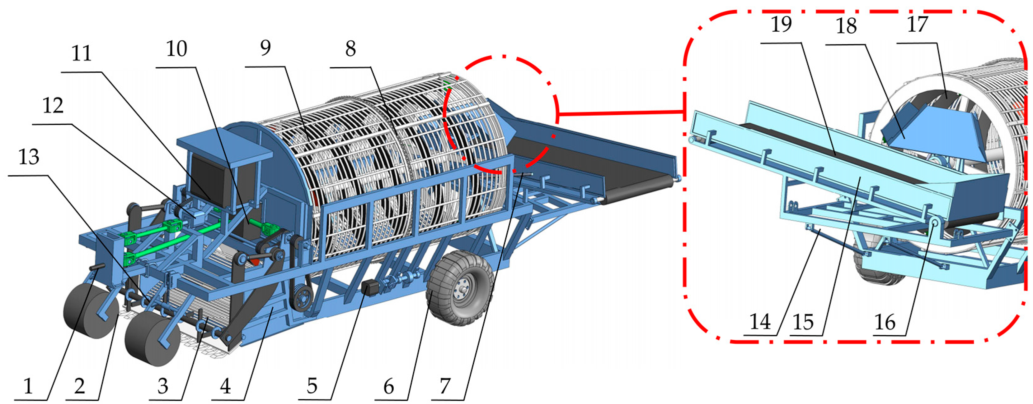
2.2. Drum Stone Picker Whole Machine Structure

The drum-type stone picker is mainly composed of a main frame, connecting frame, depth-limiting wheel, shovel, separation conveying screen, spiral separation drum, driving sprocket, sliding plate, collection box, walking wheel, and other components. The separation drum is installed on the frame, the scraper and the separation drum are connected through the separation conveying screen, the front part of the separation drum is a spiral conveying drum, the rear part is a lifting conveying drum, and the spiral conveying drum and the lifting conveying drum share a cylinder body with a screen-shaped cylinder wall. The overall structure of the spiral stone picker is shown in Figure 1.
The separation drum of the spiral drum stone picker first spirals backwards, then lifts the material to a certain height and transports it out. During the spiral conveying and lifting conveying process, filtering and separation are simultaneously realized so that the final material outlet is higher and easier to collect. The main technical parameters of the machine are shown in Table 1.

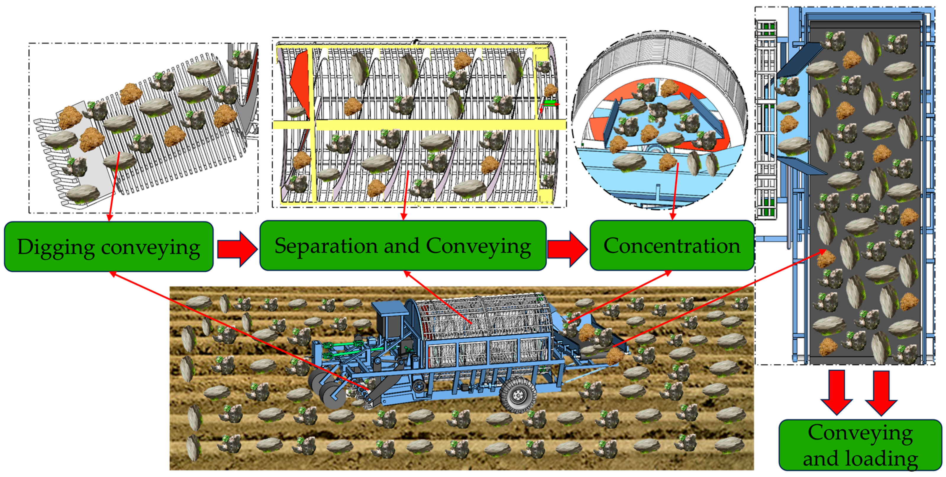
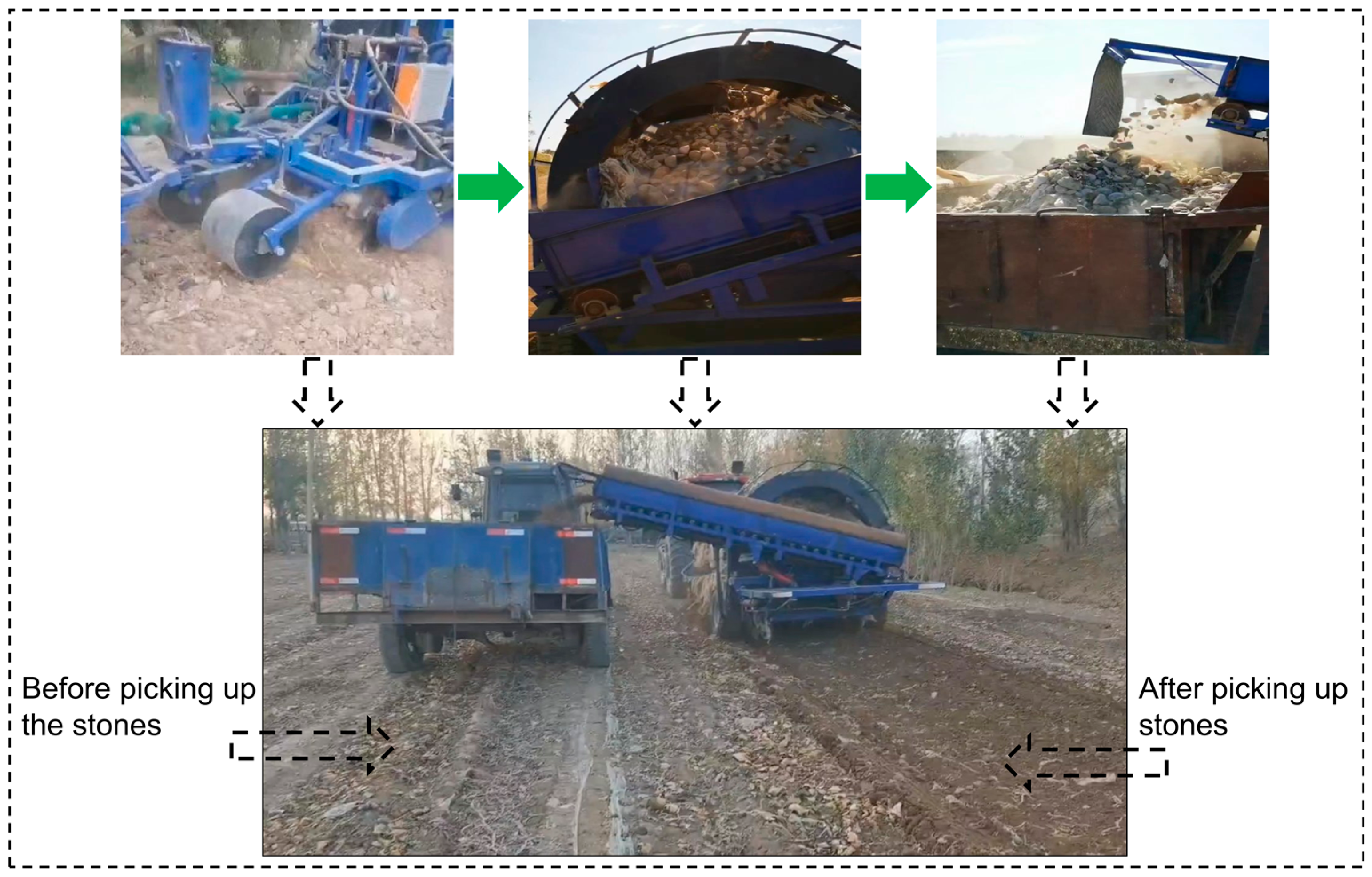
2.3. Working Principle

The working principle of the picker is shown in Figure 2. When the spiral stone picker is working in the field, the tractor is connected to the connecting frame through a three-point suspension, pulling it forward and providing power. During the forward movement, the depth-limiting wheel limits the depth. The stones dug up by the shovel and the stones on the surface of the field soil are transported upward through the separation screen and enter the spiral separation drum after preliminary separation. The soil entering the drum is separated from the roller bars under the rotation of the drum. The stones are first transported backward along the spiral blades and enter the scraper-lifting device after reaching the tail end. The scraper adopts a semi-rotating design and is connected to the spiral blade. It collects the stones and then transports them upward. When it reaches the top, it automatically flips over, causing the stones to fall onto the chute plate, slide from the chute plate into the conveyor belt, and be transported to the transport vehicle by the conveyor belt, completing the stone-picking and -collection operations of the stone picker.

2.4. Design and Performance Analysis of Key Components

2.4.1. Design of Spiral Drum Separation Device

The spiral drum separator is mainly composed of a central support shaft, a main drum body, a sprocket ring, spiral blades, a scraper, a closing plate, and other parts. The spiral blades and scrapers are installed on the inner wall of the main cylinder. A few scrapers are distributed at intervals along the circumference of the main cylinder in the rear part of the main cylinder. All the scrapers deviate from the central axis of the main cylinder in the same rotation direction. The main cylinder body comprises a cylindrical frame and a screen fixedly arranged on the cylindrical frame, the spiral blades and the front part of the main cylinder body that form a spiral conveying roller, and the scraper and the rear part of the main cylinder body that form a lifting roller. The two ends of the main shaft are rotatably connected to the frame. A sprocket ring coaxially arranged with the main shaft is fixed on the main cylinder body. The sprocket ring is connected to the sprocket on the frame through a chain. The driving device drives the sprocket to rotate the spiral drum. The schematic diagram of the spiral separation drum structure is shown in Figure 3.

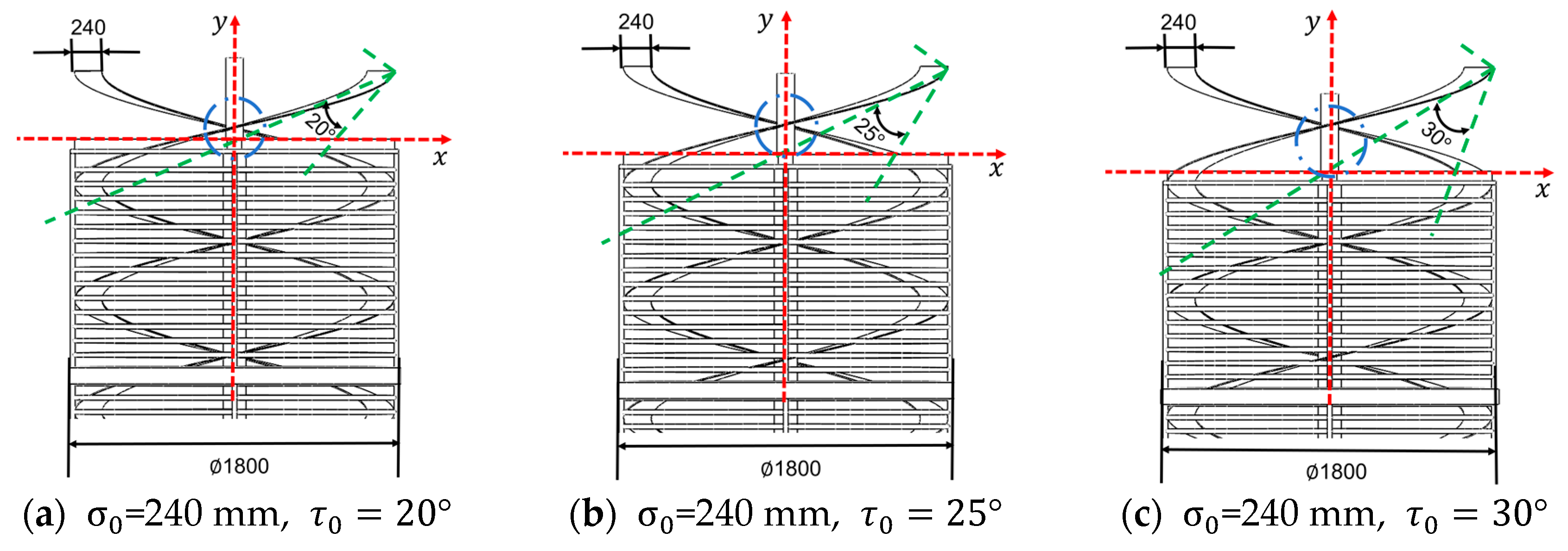
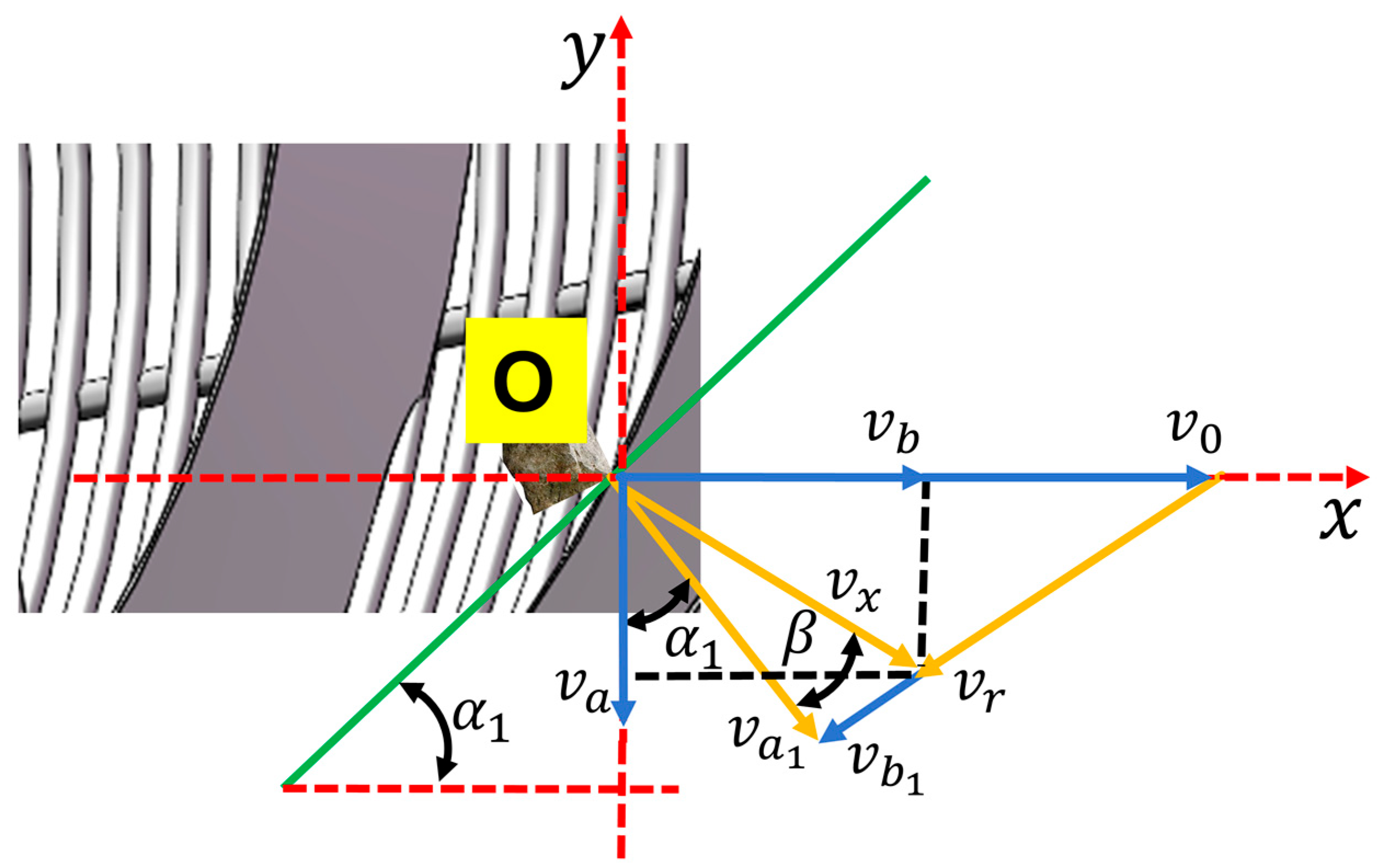
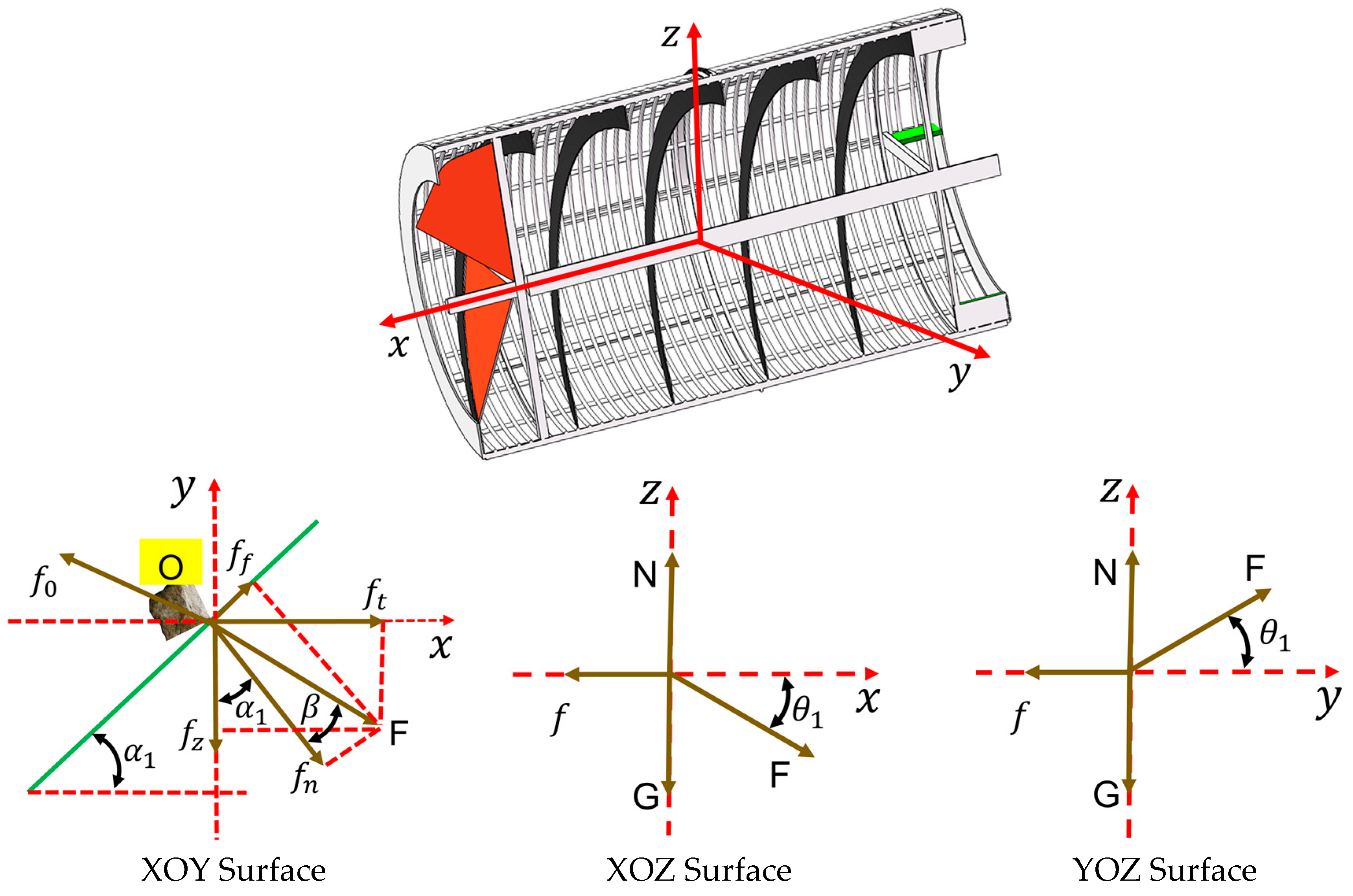
2.4.2. Spiral Blade Curve Design

The spiral blades are fixed on the inner wall of the main cylinder and their angle and shape have a significant impact on the stone-picking effect. In order to ensure that the stones are smoothly transported along the spiral blades and filtered and separated at the same time, the spiral blades are designed with an Archimedean spiral curve. This curve is continuous and smooth and can guide the stones to move upward along the spiral line while throwing out the sand and soil [17].
The equation of the Archimedean curve is as follows:
σ = σ 0 + σ θ θ n = σ n σ 0 σ n tan τ n θ ρ = σ n σ 0 θ n
where σ is the polar diameter of any point on the Archimedean curve, mm; θ is the polar angle of any point on the Archimedean curve, rad; σ n is the polar diameter of the starting point of the Archimedean curve, mm; σ 0 is the polar diameter of the end point of the Archimedean curve, mm; σ is the polar diameter increment when the polar angle of the spiral increases by unit radian, mm/rad; θ n is the polar angle of the end point of the Archimedean curve, rad; τ n is the slip angle at the end point of the Archimedean curve, (°).
It can be seen from Formula (1) that different combinations of parameters σ 0 and σ will result in different spiral blade curve equations. In order to ensure that the stone is quickly transported backward along the sliding surface of the spiral blade, it is necessary to ensure that the sliding angle τ at any point on the sliding curve is greater than the friction angle between the stone and the spiral blade [18]. According to the design requirements of the “Agricultural Machinery Design Manual” [19], σ 0 = 240 mm and σ = 4.8 mm/rad. In order to explore the sliding cutting effect of different spiral blade starting sliding cutting angles τ 0 , this paper designed three different spiral blade starting sliding cutting angles τ 0 = 20 ° , τ 0 = 25 ° , and τ 0 = 30 ° and carried out stone-picking performance tests, as shown in Figure 4.

2.4.3. Spiral Blade Size Design

The spiral blades move in a circular motion around the main axis in the drum. The length and pitch of the spiral blades determine the conveying efficiency and filtering effect of the stones in the drum. The shorter the spiral blade, the higher the conveying efficiency, but the filtering effect of soil debris is poor; the longer the spiral blade, the better the separation of stones from soil debris, but the conveying efficiency is reduced [20]. Using the Archimedean screw equation, the arc length differential of the spiral blade L can be derived as follows.
d L = r 2 + d r d θ 2 d θ
Substituting r = a θ + b and d r d θ = a , we obtain the following:
d L = a θ + b 2 + a 2 d θ
where a is the spiral blade pitch growth coefficient, m/rad, r is the distance from the origin to the point on the curve, mm, and b is the initial radius of the spiral blade, mm.
The initial radius of the spiral blade is b = 0. After simplification and integration, the length of the spiral blade L can be obtained as follows.
L = θ 1 θ 2 a 2 θ 2   +   2 a b θ   +   a 2   +   b 2 d θ L = a 2 θ n θ n 2   +   1   +   ln θ n   +   θ n 2   +   1
The stones move along the spiral blades in the drum and must not fall off, causing impact damage to the spiral blades and the drum. Using the movement of the stone at the highest point of the drum, the minimum speed of the drum can be obtained as follows:
n = 30 π × g R 30 R
where R is the radius of the roller and n is the drum speed, r/min. According to the design dimensions of the whole machine and the actual operation conditions of the stone picker in the field, the spiral blade is designed to be 4.5 turns. The drum size directly affects the contact area with the soil and crops, the linear speed, the centrifugal force, and the internal holding space. The larger the diameter of the drum, the larger the circumferential area of the drum, which means a larger contact area with the soil and crops, and can exert greater stirring and lifting forces, helping to separate crops that are deeply buried or stuck in soil blocks and reduce omissions. This is especially effective when the soil is compacted or the crops are buried deeply. The circumferential curve of the large-diameter drum is smoother, and the impact and collision on the crops when they are lifted by the lifting rod or spiral blades are relatively small. Therefore, the roller radius R is 900 mm. By substituting it into Formula (5), the minimum roller speed can be obtained. By converting the speed n and substituting it into Formulas (4) and (5) in turn, the length L of the spiral blade can be approximately designed to be 2800 mm.

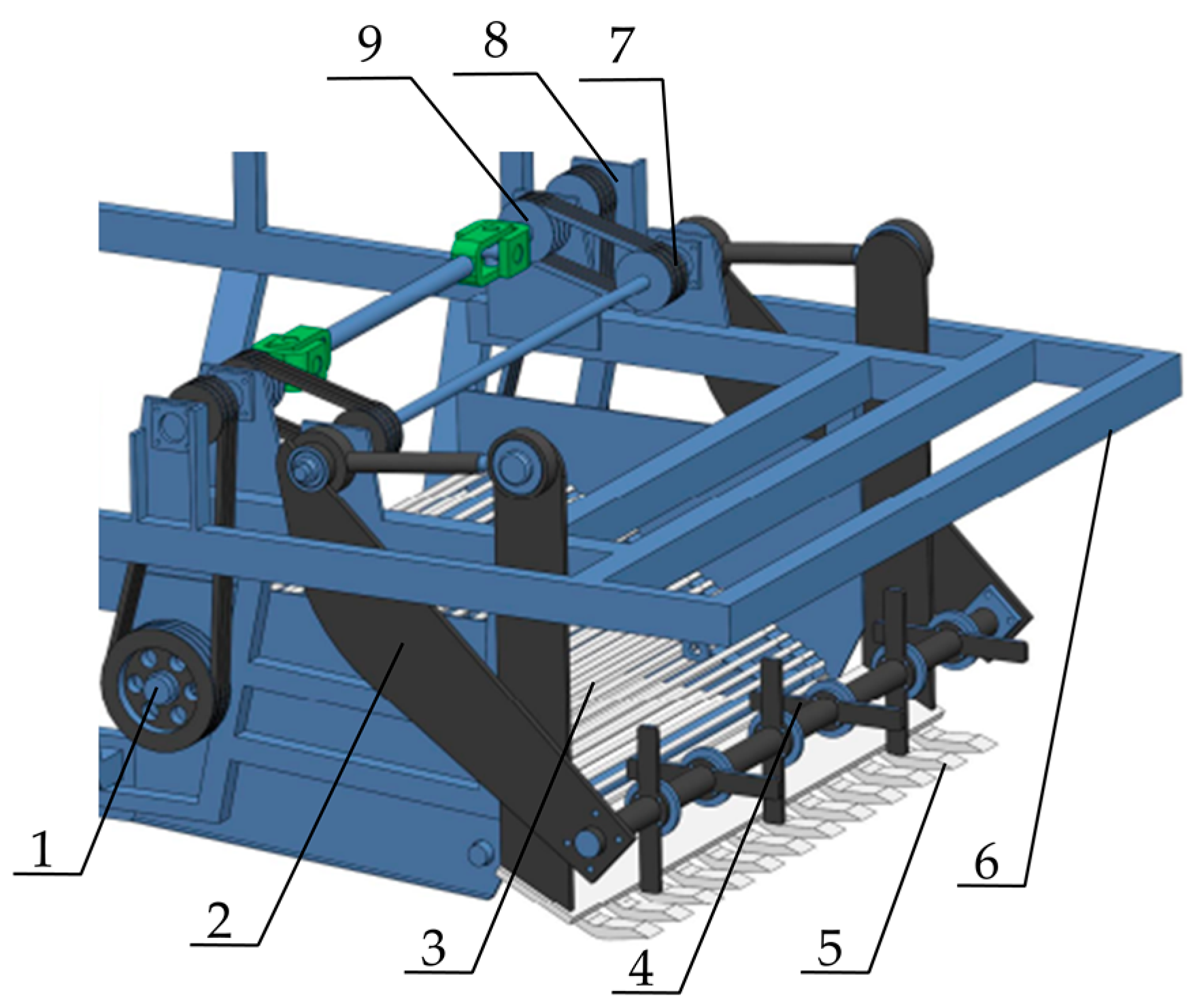
2.4.4. Design of Excavation and Conveying Device

The excavation and conveying device is mainly composed of a separation screen, an excavation shovel, a connecting plate, an auxiliary feeding soil-breaking rotary tiller, a support shaft, and other components. The structural diagram is shown in Figure 5. The soil-crushing rotary tiller is installed on the upper part of the digging shovel. When working, the digging shovel will turn over stones, soil mixtures, etc., and transport them backwards. The rotary tiller will crush some of the dug soil blocks and separate the film, weeds, etc., on the soil surface to prevent the roller from being entangled during the backward transportation and separation process. The stone and soil mixture after preliminary separation is transported to the separation screen, which is driven by the driving shaft to perform secondary separation on the stone and soil mixture and then transport it to the drum.
The excavator shovel is installed at the bottom of the front end of the frame and consists of multiple blades. It is responsible for transporting stones on the soil surface and picking up stones buried in the soil. The blades are required to have automatic cleaning and good soil penetration performance [21]. When picking up stones in the field, the stones are relatively hard. In order not to damage the shovel and to collect the stones effectively, a flat-type oblique-edged shovel is selected.
The shovel cuts into the soil layer, peels off and lifts the surface soil and stone mixture, and uses the density and size differences between stones and soil to achieve initial separation. The shovel blade is designed to adapt to stones of different sizes and hardness and reduce the disturbance of the soil by the shovel blade. Assuming that the initial sliding angle between the blade and the ground is α , ( ° ), the forward speed of the machine is v , m/s, the soil density is ρ , kg/m3, the blade width is B, mm, the digging depth is d, mm, μ is the friction factor between the blade and the material, and the vertical resistance F v mainly comes from the compression and shearing of the soil. The empirical formula is as follows.
F v = k ρ g B d 2 sin α
In the formula, k is the soil resistance coefficient, and its value range is usually 0.5~2, and g is the acceleration due to gravity, which is 9.8 m/s2. The shovel blade is fixed on the digging shovel support plate to ensure that the shovel blade cannot break or deform. The blade is regarded as a cantilever beam, and the cross section of the blade is approximately rectangular. The maximum bending moment M and section inertia moment I at the root of the blade are as follows:
M = F v L I = D H 3 12
where L is the length of the blade, mm, the thickness of the blade is H, mm, and the width is D, mm.
Combining the two Equation (10), the maximum bending stress γ at the root of the blade can be obtained as follows.
γ m a x = M H / 2 I = 6 F v L D H 2
When the blade is moving forward, it is necessary to ensure that the resistance to the blade’s movement is small to reduce the energy consumption of the entire machine. From Formula (8), we can see that the smaller α is, the smaller the resistance on the shovel is. When α 0 , the resistance is the smallest, but the stones and soil should slide away from the shovel smoothly. From the empirical formula, we obtain the following.
α o p t = tan 1 μ d L
In order to avoid the blade from breaking due to being too long, the corresponding strength conditions of the blade can be obtained.
γ m a x γ L 2 γ × D H 2 3 k ρ g d 2 sin α
When the stone picker is operating in the field, it is mainly used in areas with more stones. According to the literature [22], the soil density ρ is taken as 2.7 g / c m 3 . The excavation depth is determined by the depth-limiting wheel and is generally controlled at 200~300 mm according to field operation conditions. The blade width B is 25 mm and the thickness H is 15 mm. According to Formula (10) and the forward speed of the stone picker, the blade material is selected as 41B30M5 steel, which has high strength and toughness. Substituting each coefficient in turn, the blade length is designed to be 240 mm.

2.4.5. Analysis of Conveying and Separation Performance of Drum Screen

After the stone and soil mixture enters from the feeding port, it is transported backward along the central axis of the drum screen along the spiral blades. During the conveying process, the soil mixture collides with itself due to the rotation of the drum and is separated from the bars of the drum screen into the soil where the stones have been picked up. After the stones are conveyed to the tail end of the drum screen, they are lifted to the top by the scraper and fall onto the chute for collection. Assuming that the mass m of the stones transported on the screen surface is proportional to the mass of the soil mixture separated instantaneously through the screen, and k 1 is the coefficient of variation of the instantaneous separation amount of the soil mixture with the mass of the stones transported in the drum, then we obtain the following equation.
d m d t = k 1 m
The mass m of the stones transported on the drum screen decreases as the transport time t increases. Integrating Equation (11) yields the following.
ln m = k 1 t + c
From Formula (12), we can know that the mass of the soil mixture m 0 that is not separated from the drum screen accounts for the mass of the total material in the drum. Then, the separation efficiency of the soil mixture entering the drum can be calculated according to the definition of the separation efficiency of the picker [23].
m m 0 + m = e k 1 t η = 1 m m 0 + m = 1 e k 1 t × 100 %
There are many types of actual separation machines, and the coefficient k 1 for calculating the separation efficiency of the soil mixture in the drum is not unique. Therefore, the coefficient y is introduced, and k 1 = 1 a is set to obtain a simplified calculation formula for the more general separation efficiency.
η = t y a + t y × 100 %
Assuming the average speed of the stone passing through the spiral blade is v0, then t = L v 0 , and the separation efficiency formula can be replaced by the following.
η = L y a v 0 y + L y × 100 %
It can be seen from Equations (14) and (15) that the residence time of the soil mixture in the drum screen affects the separation performance of the separation screen, and the residence time is related to the axial movement distance of the soil mixture and the conveying speed. When the conveying distance remains unchanged, the axial speed of the soil mixture is too fast, and it is conveyed to the scraper before being separated from the drum, resulting in the poor separation effect of the drum screen; if the axial speed of the soil mixture is slow, the stones and soil mixture will be retained in the drum screen for a long time, reducing the conveying efficiency of the stones and causing blockage inside the drum. In order to ensure that the drum screen has good conveying performance and separation efficiency, the conveying length and separation time of the drum screen should be determined [24,25].
The speed of the stone on the flow-aiding spiral blade is decomposed, as shown in Figure 6. The linear speed of the stone moving with the spiral blade is v 0 , the sliding speed of the stone relative to the blade is v r , and the spiral angle of the guiding spiral blade is α 1 . In the actual movement process, due to the effect of friction, there is an angle b between the movement speed of the stone and the tangent direction of the spiral blade. During the conveying process, the movement of stones on the spiral blades is divided into two directions. One is axial movement along the height direction of the spiral blades, that is, the conveying direction of the drum; the other is circular movement, along the tangential direction of the spiral blades, driven by the rotation of the spiral blades. In the figure, v x is the actual speed of the stone, v a is the axial speed of the stone, and v b is the circumferential speed of the stone; v a 1 and v b 1 are the cloud activity speed and the sliding speed of the stone relative to the blade without considering the friction force. The decomposition formula is as follows:
v a = t g n 1 μ 1 t g 2 π R 60 1 + t g 2 π R 2 v b = t g n t g 2 π R + μ 1 60 1 + t g 2 π R 2
t x = 60 L 1 + t g 2 π R 2 t g n t g 2 π R + μ 1
where μ 1 is the friction coefficient between the stone and the surface of the flow-aiding spiral blade, t x is the time it takes for the stone to pass through the screen completely, s, and t g is the pitch of the spiral blade in the screen, mm.
In order to design and clarify the appropriate structure and operating parameter range of the drum screen, the stones in the drum are simplified as point masses, and the forces acting on the spiral blades are analyzed [26]. The forces on the stone during its movement include its own gravity G, the normal thrust f n of the spiral blade on the stone, the friction f 0 between the stone and the screen, and the friction f f between the stone and the blade, as shown in Figure 7. The angle of deviation of the resultant force F acting on the stone is equal to the friction angle β , and α 1 is the angle between the line connecting the stone and the axis and the vertical line. The resultant force on the stone is decomposed into the tangential force f z along the spiral blade and the axial force f t .
f z = F cos α 1 + β f t = F sin α 1 + β α 1 = tan 1 t g / 2 π R β = tan 1 μ 1
In order to prevent the stones from falling off the spiral blades during transportation and to smoothly transport them to the scraper at the end of the drum, the driving force on the stones during movement must be no less than the axial component of the tangential friction force f f between the stones and the blades under the following condition.
f n cos α 1 f f sin α 1 + f 0 sin 90 ° α 1 β
Simplifying Formula (22), we obtain the following:
f n cos α 1 f f sin α 1 f f = f n tan β f 0 = μ 2 m x g
where μ 2 is the friction coefficient between the screen and the material, which is taken as 0.5. From Equations (18)–(20), we can know that α 1 is less than 41.25°, and we can conclude that the pitch of the spiral blade should be less than 1.53 m.
After the conveying performance requirements of the drum screen are met, the layout of the spiral blades in the drum should also meet the separation requirements for the soil mixture so that, after the soil mixture enters the drum from the feeding port, the center of gravity can be moved below the screen plane in time; that is, the time for the soil mixture to move one screen hole on the drum screen must be greater than the time required for the center of gravity of the soil mixture to move below the screen plane. The movement trajectory of the soil mixture on the drum screen surface is shown in Figure 8.
As shown in Figure 7, the time t 2 for the soil mixture to move a distance D k in the drum should be greater than the time t 1 required for the soil mixture to move a distance r x along the radial direction of the drum. D k is slightly greater than the center distance L x between the two rods of the drum screen. The minimum value of 35 mm is taken for calculation. The condition is as follows:
r x = 0.5 g t 1 L x = v x t 2 v x = v a 2 + v b 2 t 1 t 2
where r x is the radius of soil block in the general field, which is 25 mm. Combining Equations (19) and (21), it can be seen that, when the rotating speed of the drum screen and the center distance between the two rods of the drum screen are the minimum, the pitch of the spiral blade can take the maximum value. Substituting it into Equation (21), it can be seen that the pitch of the spiral blade should be less than 960 mm. According to the literature, the minimum value of the spiral blade pitch is generally greater than 0.8 R; that is, the pitch is greater than 720 mm [27]. According to the comprehensive design, the pitch range of the spiral blades of the screen inside the drum is 720 mm < t g < 960 mm.

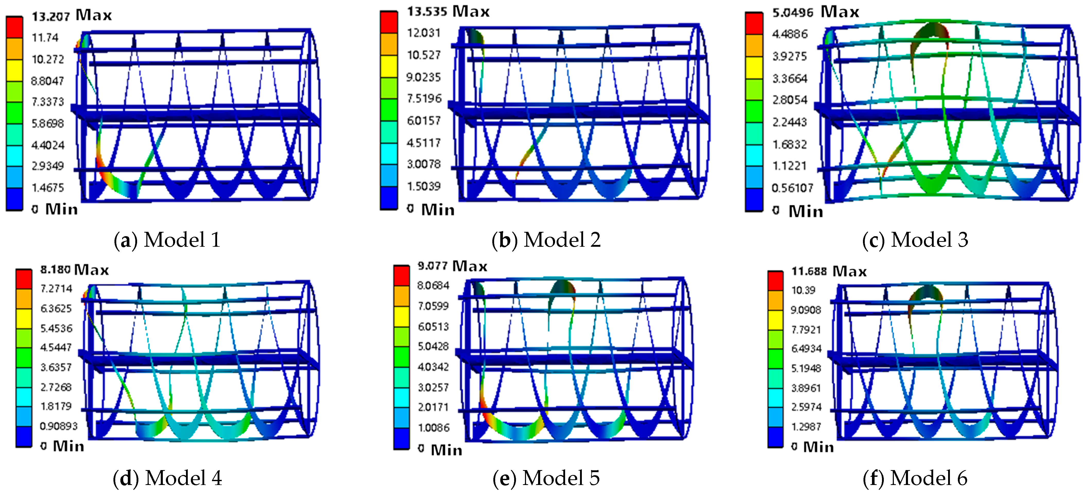
2.5. Modal Analysis of Helical Blades

Modal analysis is a numerical technique for calculating the vibration characteristics of a structure, including its natural frequencies and mode shapes. When the operating frequency of the spiral blade (such as rotation frequency and material impact frequency) coincides with its natural frequency, resonance will occur, causing the amplitude to increase sharply. The vibration stress exceeds the fatigue limit of the material, causing crack propagation and ultimately leading to blade fracture [28,29]. Therefore, constrained modal analysis was carried out on the actual working condition of the spiral blade. The simulation was carried out in ANSYS Workbench 2024 R1, the total deformation was taken as the research target, and the sixth-order analysis was performed.
The material of the spiral blade is 45 steel, which has an elastic modulus of 200 MPa, a density of 7850 kg/m3, a Poisson’s ratio of 0.3, and a yield strength of 355 MPa. The material was assigned to the part and the hexahedral unit mesh is divided. The calculation and analysis are carried out, and the modal analysis diagram obtained after the calculation is shown in Figure 9.
The sixth-order vibration frequency of the spiral blade ranges from 23.774 Hz to 31.753 Hz. The third-order bending vibration has the greatest influence on the deformation of the spiral blade, with a vibration frequency of 26.224 Hz. The overall deformation of the spiral blade is large and bulges toward the positive direction of the Z axis; the fourth-order and fifth-order bending vibrations have moderate effects on the deformation of the spiral blade, which is manifested as most of the spiral blade being deformed, and the deformation of the middle part is the largest, making the spiral blade flat; the first-order, second-order, and sixth-order bending vibrations have little effect on the deformation of the spiral blade, causing deformation only on part of the spiral blade. The deformed part becomes flat and the deformation angle is different. Table 2 shows the natural frequencies and maximum deformations corresponding to each order. The maximum speed of the drum during operation is 42 rpm. The basic conversion relationship between the speed and frequency of the spiral blade is n = 60 × f. The maximum excitation frequency of the spiral blade is 0.7 Hz, which is much lower than the minimum natural frequency of the spiral blade, 23.774 Hz. Therefore, the spiral blade will not produce resonance during operation and the structural design is reasonable.

3. Results

3.1. Test Methods

The main test factors that affect the picking quality of the drum stone picker include drum length, excavation depth, starting sliding angle of the spiral blade, forward speed of the stone picker, and drum speed [30]. In the actual operation process of the stone picker, the drum length and the excavation depth remain unchanged. The starting sliding angle of the spiral blade, the forward speed of the stone picker, and the drum speed are the main factors affecting the picking quality of the stone picker. If the initial sliding angle of the spiral blade is too large, the sliding effect of the spiral blade will be enhanced, and the separation force between soil and stones will increase; if the initial sliding angle of the spiral blade is too small, the sliding effect of the spiral blade will be weakened, and the blade’s ability to push materials will increase [31,32]. Increasing the forward speed of the stone picker and the rotation speed of the drum can increase the picking efficiency of the stone picker, but there may be missed pickings, and too high a rotation speed will increase the centrifugal force of the stone movement in the drum, resulting in insufficient separation of the stone and soil and reducing the picking quality of the stone picker. Therefore, combined with the design parameters of relevant picking devices at home and abroad and the actual operating conditions of the machine, through the preliminary stone-picking performance test, the range of each test factor was determined as follows: the forward speed of the stone picker is 0.5~0.8 m/s, the drum speed is 20~30 rpm, and the starting sliding angle of the spiral blade is 20°~30°.
To ensure the accuracy of the experiment, this paper divides the experiment into response surface optimization test and prototype field test, which are combined and verified with each other. The field test of the stone picker was conducted in Fuhai County, Altay Prefecture, Xinjiang in September 2024. The test site is located at 48°1′ N, 89°04′ E. The average temperature during the test was 27°. The soil type was chestnut soil. There were stones, clods, weeds, films, etc., on the land during the test. According to the actual field conditions and the requirements of this experiment, a total of five test plots were set up. Each plot included the back and forth picking stroke of the drum-type stone picker and the control stone-picking effect area. The length of each plot was 60 m, and the transition zone was 3 m apart between the plots. The test was carried out within the range of various test factors. After the test, the operating data of various parameters of the stone picker were collected, the stone composition and soil and clod content in the collection box were observed, and the weight of stones picked up in each plot was counted.

3.2. Test Indicators

The picking rate and soil content are important indicators for evaluating the picking quality of stone pickers. According to NY/T3884-2021 “Technical Specifications for Quality Evaluation of Farmland Stone Pickers” [33], the picking rate R 1 and soil content R 2 are used as evaluation indicators of the test. The specific formula is as follows.
R 1 = Q s Q s + Q e × 100 % R 2 = Q x Q z × 100 %
In the formula, Q s is the mass of the picked-up stones, kg, Q e is the mass of the stones within the size range that should be picked up within the stone-picking depth, kg, Q x is the mass of the soil blocks in the picked up objects, kg, and Q z is the total mass of the picked-up objects, kg.
The experimental scheme is a three-factor three-level Box–Behnken test. The Design-Expert 13.0 software is used to perform a response surface test on the three experimental factors of the drum stone picker’s forward speed X 1 , drum speed X 2 , and spiral blade starting sliding angle X 3 . The experimental factor codes and levels are shown in Table 3.

3.3. Test Results

This experiment adopted a three-factor three-level Box–Behnken test, which was carried out in the software Design-Expert 13.0. A total of 17 groups of test data were used. Variance analysis and multivariate regression fitting were performed on the data to obtain the regression equations of the test indicators’ picking rate and soil content. Finally, the interaction and significance of each test factor were tested and analyzed. The test results are shown in Table 4.

3.4. Difference Analysis

The experimental data in Table 4 were analyzed by Design-Expert 13.0 software, and the quadratic regression models of the drum stone picker operation picking rate R 1 and soil content R 2 were obtained as follows.
R 1 = 66.82644 + 111.12444 X 1 + 7.03408 X 2 + 2.86208 X 3 0.076667 X 1 X 2 1.15667 X 1 X 3 + 0.0098 X 2 X 3 59.91111 X 1 2 0.14302 X 2 2 0.04682 X 3 2 R 2 = 49.20756 + 32.55389 X 1 + 2.69225 X 2 + 0.807667 X 3 + 0.08 X 1 X 2 0.443333 X 1 X 3 + 0.0051 X 2 X 3 18.35556 X 1 2 0.05712 X 2 2 0.01322 X 3 2
By conducting a lack-of-fit test on the regression equation, the variance analysis of the picking rate and soil content of the drum stone picker can be obtained, as shown in Table 5.
The variance analysis of the picking rate and soil content of the stone picker is shown in Table 5. When p < 0.01, it indicates that the model is extremely significant and the lack of fit item p > 0.1, indicating that the model is highly reliable. It can be seen that experimental factors X 1 and X 2 have significant effects on the picking rate of the stone picker; in the interactive effect of experimental factors, X 1 2 , X 2 2 , X 3 2 , X 1 X 3 have a very significant effect on the picking rate of the stone picker, X 2 X 3 have interactive effects on the picking rate of the stone picker, and the other experimental factors have no significant effect on the picking rate of the stone picker. According to the coefficients of the regression equation, the factors that affect the picking rate of the stone picker are X 2 , X 1 , and X 3 from large to small. The reason is that, as the drum speed increases, the centrifugal force on the stones increases, forcing the stones to be thrown quickly to the collection device, reducing the missed collection due to gravity sedimentation. At the same time, as the speed increases, the conveying efficiency of the blades increases, which directly affects the stone-picking effect of the stone picker.
As can be seen from the above, experimental factors X 1 , X 2 and X 3 have significant effects on the soil content of the stone picker; among the interactive effects of various experimental factors, X 1 2 , X 2 2 , X 3 2 , X 1 X 3 and X 2 X 3 all have extremely significant effects on the soil content of the stone picker, and X 1 X 2 has no significant effect on the soil content of the stone picker. According to the coefficients of the regression equation, the factors that affect the soil content of the stone picker are X 2 , X 1 , and X 3 from large to small. The reason is that, when the speed increases, the centrifugal force generated by the drum increases, and the soil mixture is thrown away from the stones more efficiently and discharged through the screen, reducing mixing. Secondly, the higher speed promotes the collision and separation of soil and stones, especially for adhesive soil.

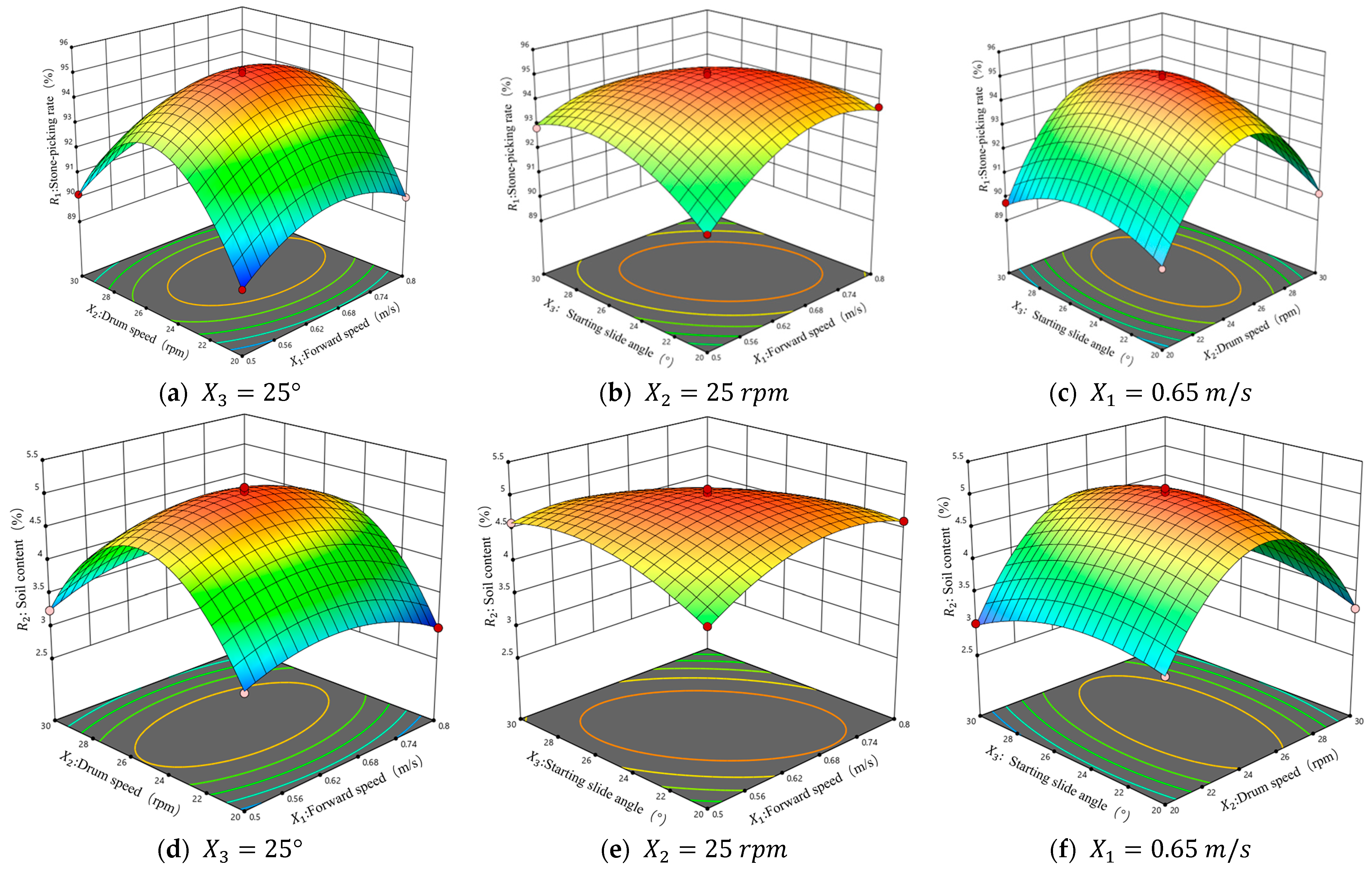
3.5. Response Surface Analysis of Stone Pick-Up Rate and Soil Content

Using Design-Expert13.0 software, response surface analysis was performed to obtain the response surface of the interaction between the forward speed of the drum stone picker, the drum speed, and the initial sliding angle of the spiral blade on the picking rate and soil content of the stone picker, as shown in Figure 10.
It can be seen from Figure 9a–c that the response surfaces (a) and (c) are steeper, while the response surface (b) is flatter. Keeping one of the influencing factors unchanged and increasing the other two factors, the most significant factor affecting the picking rate of the stone picker is the drum speed X 2 . The picking rate of the stone picker shows a trend of first increasing and then decreasing, and the parameter range with the greatest impact is the drum speed of 24–28 rpm. The forward speed and initial sliding angle of the stone picker have a relatively gentle effect on the picking rate of the stone picker. The parameter ranges with more significant effects are a forward speed of 0.56–74 m/s and an initial sliding angle of 22°–28°. If the initial sliding angle and the forward speed increase at the same time, the sliding cut inside the drum will be too deep and the processing time will be insufficient, resulting in a decrease in the picking rate of the stone picker. Increasing the drum speed and the starting sliding angle at the same time can enhance the sliding separation effect. At the same time, the centrifugal force assists in throwing soil, greatly improving the stone-picking rate of the stone picker.
It can be seen from Figure 9d–f that the response surfaces (d) and (f) are steeper, while the response surface e is relatively flat. As can be seen from the above, the most significant factor affecting the soil content of the stone picker is the drum speed X 2 . The soil content of the stone picker shows a trend of first increasing and then decreasing. The parameter range with the greatest impact is the drum speed of 24–26 rpm. The influence of the forward speed and the initial sliding angle of the stone picker on the soil content of the stone picker is relatively gentle. The parameter ranges with more significant impact are forward speed of 0.56–68 m/s and initial sliding angle of 22–26°. It can be seen that, by keeping the forward speed unchanged and increasing the drum speed, the number of times the stone and soil mixture is processed per unit length in the drum increases, the separation capacity of the drum is increased, and the soil content of the stone picker is reduced. However, if the speed is too high, it will increase the energy consumption of the stone picker and aggravate the mechanical damage of the drum screen.

3.6. Parameter Optimization and Field Trial Verification

The optimization module regression model in Design-Expert13.0 software was used to solve the problem. According to the requirements for the harvest quality of field stone pickers in NY/T3884-2021 [33] “Technical Specifications for Quality Evaluation of Farmland Stone Pickers”, the optimization constraints were selected as follows.
m a x R X = R 1 X 1 , X 2 , X 3 m i n R X = R 2 X 1 , X 2 , X 3 s . t . 80 % R 1 100 % 0 R 2 8 %
Through optimization solution, when the forward speed of the drum stone picker is 0.726 m/s, the drum speed is 30 rpm, the initial sliding angle of the spiral blade is 26.214°, the picking rate of the stone picker is 91.458%, and the soil content is 3.513%.
In order to verify the accuracy of the optimization theoretical model, verification was carried out on the basis of the response surface test. The forward speed of the drum stone picker was selected as 0.72 m/s, the drum speed was 30 rpm, and the starting sliding angle of the spiral blade was 26.2°. The test was carried out strictly in accordance with the test plan in 2.7 and the results were averaged. The field test is shown in Figure 11.
The verification data are shown in Table 6. Field tests show that, when the forward speed of the drum stone picker is 0.72 m/s, the drum speed is 30 rpm, the starting sliding angle of the spiral blade is 26.2°, the picking rate of the drum stone picker is 91.42%, with an error of 0.038% compared with the predicted value, and the soil content is 3.567%, with an error of 0.054% compared with the predicted value. The results showed that the optimized model was reliable and close to the field test and they also verified the accuracy of the best parameter combination scheme.

4. Discussion

By comparing it with related research, the operating performance of the drum stone picker can be analyzed. Zhang Jia et al. [11] designed a spiral-tooth stone picker. In field tests, when the starting sliding angle of the excavation tooth blade was 14.73°, the forward speed of the machine was 0.34 m/s, the blade shaft speed was 171.89 r/min, and the stone picker had the best stone-picking effect and an average stone-picking rate of 90.04%. Compared with this machine, the stone-picking effect is better. The 1JS-100 soil stone picker designed by Zhan Xiaomei et al. [12] takes an average of 79.9 s to pick up 30 m of stone, which is equivalent to an operating efficiency of 0.135 hm2/h in pure working time. The average stone-picking rate is 95.4% and the soil content of the stone is 9.9%. Niu Cong et al. designed a shovel-sieve-type farmland stone pick-up and collection machine, which can pick up and collect stones with a diameter greater than 34 mm within the depth range of 0~350 mm in the surface soil of farmland and carried out the optimization test of the field operation parameters. The optimal parameter combination of the soil content of the stone–soil mixture in the collection box at the time of the field test is 10.73%, and the simulation test results under the same conditions have small differences, which shows that the simulation optimization of the working parameters are accurate and reliable. The drum-type stone picker designed for this machine has a picking rate of 91.42% and a soil content of 3.567% when operating in the field, which is similar to the operating performance of the above-mentioned stone picker.
Compared with the stone pickers designed in the industry, this machine is designed to use a drum to transport stones. Spiral blades are arranged inside the drum. While enhancing the conveying capacity of the drum screen, it can effectively separate the mixture of stones and soil and improve the picking rate of the stone picker. At the same time, the drum structure supports continuous feeding and stone discharge, which is suitable for large-scale farmland operations. The expected size of the stones to be picked up is mainly determined by the roller gap. Theoretically, any stone that is larger than the gap between the bars can be caught and carried backwards by the spiral belt. However, larger soil clods may not be able to enter the space between the drum and the cover, or may cause huge loads on the drum, spiral blades, bearings, and drive system during the lifting process, resulting in damage and jamming, etc. Therefore, the most effective, safest, and most efficient stone size range for spiral drum stone pickers is usually between 50 mm and 18 mm. Stones within this range can be effectively separated and smoothly transported.
Secondly, when there are large undulations, gullies, or ridge terrain in the actual field, the consistency of the Archimedes curve roller’s penetration depth and the picking effect may be challenged, resulting in local missing or uneven picking depth. Secondly, foreign objects such as mixed stones and hard root stubble in the field can cause impact damage to the Archimedes curve roller. These hard objects may cause additional wear to the precisely designed curve track mechanism. In the future, contouring mechanisms or highly adaptive adjustment systems should be developed to enable the roller to automatically adjust its height and angle according to the undulations of the surface, and composite materials such as wear-resistant and viscosity-reducing coatings should be applied to the surfaces of key contact components.

5. Conclusions

(1)
Aimed at solving the problems of low picking rate and high soil content in the existing stone pickers, a drum stone picker based on the Archimedean curve was designed. The stone picker drum screen, spiral blades, and excavation blades were designed, the movement of stones on the spiral blades was analyzed, the parameter values and dimensions of key working parts were determined, and the reliability of the spiral blades was checked using ANSYS Workbench software.
(2)
Through the preliminary performance test of the stone picker, the forward speed of the stone picker, the rotation speed of the drum, and the starting sliding angle of the spiral blade were determined as the test influencing factors, and the picking rate and soil content of the stone picker were determined as the test indicators. A three-factor and three-level response surface test was carried out in the Design-Expert13.0 software, which was divided into 17 groups of experiments. The regression model of the picking rate and soil content of the stone picker were obtained through multivariate fitting. The test results were analyzed and the influence of the interaction between the experimental factors on the picking rate and soil content of the stone picker was obtained.
(3)
The response surface optimization of the influencing parameters of the drum stone picker was carried out. When the forward speed of the drum stone picker was 0.726 m/s, the drum speed was 30 rpm, the initial sliding angle of the spiral blade was 26.214°, the picking rate of the stone picker was 91.458%, and the soil content was 3.513%. Field verification tests were carried out using the optimized parameter approximations. The drum stone picker had a picking rate of 91.42%, with an error of 0.038% compared with the predicted value, and a soil content of 3.567%, with an error of 0.054% compared with the predicted value. The results show the feasibility of the overall structure scheme and the accuracy of the optimal parameter combination scheme.

Author Contributions

Conceptualization, B.W., F.G. and F.W.; methodology, B.W. and F.W.; software, C.L.; validation, M.G. and J.N.; formal analysis, B.W.; investigation, W.L. and J.P.; resources, C.L.; data curation, C.L.; writing—original draft preparation, C.L.; writing—review and editing, C.L.; visualization, F.G.; supervision, F.W.; project administration, B.W.; funding acquisition, M.C. All authors have read and agreed to the published version of the manuscript.

Funding

This project was funded by the China Postdoctoral Science Foundation (2024T170443); the China Postdoctoral Science Foundation (2023M731824); and the Nanjing Postdoctoral Outstanding Research Project.

Institutional Review Board Statement

Not applicable.

Data Availability Statement

The data presented in this study are available in the article.

Conflicts of Interest

The authors declare no conflicts of interest.

References

  1. Yu, Y.Z.; Gao, L.X.; Ma, X.L.; Ma, F.; Zhao, J.S. Research progress of soil stone picker. J. Agric. Eng. 2007, 23, 274–279. [Google Scholar]
  2. Chen, W.; Zhu, J.P.; Chen, S.B.; Yuan, D.; Yao, K.H.; Peng, Z.M. Current status of agricultural mechanization development in sloping cultivated land in China. Agric. Mech. Res. 2017, 39, 1–5, 11. [Google Scholar]
  3. Zhang, J.; Wang, H.; Li, C.J.; Zhang, J.X.; Du, Y.K. Analysis of the development trend of mechanization technology for soil stone picking in farmland based on patent measurement. Chin. J. Agric. Mech. Chem. 2024, 45, 250–256. [Google Scholar]
  4. Li, X.; Salem, A.; Liu, Y.; Sun, B.; Shi, G.; He, X.; Wang, D.; Chang, Z. Design and Experiment of a Dual-Disc Potato Pickup and Harvesting Device. AgriEngineering 2025, 7, 148. [Google Scholar] [CrossRef]
  5. Li, Y.; Hu, Z.; Gu, F.; Wang, B.; Fan, J.; Yang, H.; Wu, F. DEM-MBD Coupling Simulation and Analysis of the Working Process of Soil and Tuber Separation of a Potato Combine Harvester. Agronomy 2022, 12, 1734. [Google Scholar] [CrossRef]
  6. Zhan, X.M.; Nie, H.L.; Li, Y.L.; Cao, Z.H.; Yang, H.; Cui, J.B. Research on the whole mechanization operation system of oilseed rape production in the area of suitable mechanization improvement. Chin. J. Agric. Mech. Chem. 2019, 40, 197–203. [Google Scholar]
  7. Cao, S.; Xie, J.; Wang, H.; Yang, Y.; Zhang, Y.; Zhou, J.; Wu, S. Design and Operating Parameters Optimization of the Hook-and-Tooth Chain Rail Type Residual Film Picking Device. Agriculture 2022, 12, 1717. [Google Scholar] [CrossRef]
  8. Fang, W.; Wang, X.; Han, D.; Ohiemi, I.E. Analysis of the Resistance to Teeth During the Picking Process Based on DEM-MBD Coupling Simulation. Agronomy 2025, 15, 1002. [Google Scholar] [CrossRef]
  9. Hu, S.; Xin, J.; Zhang, D.; Xing, G. Research on the Design Method of Camellia Oleifera Fruit Picking Machine. Appl. Sci. 2024, 14, 8537. [Google Scholar] [CrossRef]
  10. Li, S.Q.; Liu, X.G.; Li, D.L. Stress dynamic modeling and simulation of farmland stone picker based on kinetic analysis. South. Agric. Mach. 2024, 55, 24–27. [Google Scholar]
  11. Zhang, J.; Du, Y.K.; Ma, X.W.; Ma, S.T.; Xiao, P.; Zhang, J.X. Design and test of Archimedean curve based spiral toothed stone picker. J. Agric. Mach. 2025, 56, 290–300. [Google Scholar]
  12. Zhan, X.M.; Li, Y.L.; Cao, Z.H.; Yang, Q.H.; Cui, J.B. Design of 1JS-100 soil stone picker. Agric. Mech. Res. 2023, 45, 69–73. [Google Scholar]
  13. Niu, C.; Xing, Y.T.; Yan, C.C.; Tan, H.C.; Ma, S.; Xu, L.M. Simulation and test of shovel-screen type farmland stone pickup and collection machine. J. China Agric. Univ. 2022, 27, 221–233. [Google Scholar]
  14. Jiang, T.; Li, H.T.; Huang, M.H.; Zhang, M.; Jin, M.; Guan, Z.H. Design and test of spiral staggered row threshing drum for combine harvester. J. Agric. Mach. 2025, 56, 314–324. [Google Scholar]
  15. Chen, P.L.; Su, J.H.; Xu, J.; Liu, M.H. Design and experiment of vertical spiral ditch fertilizer applicator for hilly orchard. J. Agric. Mach. 2024, 55, 223–233, 274. [Google Scholar]
  16. Chen, Y.; Xing, R.; Liu, X.; Zhang, H.; Li, H. Design and Test of Potato Seedling Killing and Residual Film Recycling Integrated Machine. Agronomy 2024, 14, 2269. [Google Scholar] [CrossRef]
  17. Zhu, H.B.; Wu, X.; Bai, L.Z.; Wang, M.P.; Lei, F.L.; Fang, Y. Design and test of a shaftless spiral fertilizer discharge and delivery device for no-till planter. J. Agric. Mach. 2023, 54, 125–134. [Google Scholar]
  18. Ding, W.M.; Peng, S.Z. Study on the slip angle of rotary plow knives and the slip angle equation. J. Agric. Eng. 1995, 11, 67–72. [Google Scholar]
  19. China Academy of Agricultural Mechanization. Agricultural Machinery Design Manual; China Agricultural Science and Technology Press: Beijing, China, 2007. [Google Scholar]
  20. Chen, Q.; Zhang, S.; Hu, G.; Zhou, J.; Zhao, J.; Chen, Y.; Chen, J.; Gao, S.; Chen, Y.; Shi, T. Parameter Optimization of the Harvest Method in the Standardized Hedge Cultivation Mode of Lycium barbarum Using Response Surface Methodology. Horticulturae 2022, 8, 308. [Google Scholar] [CrossRef]
  21. Liao, Q.X.; Xie, H.M.; Zhang, Q.S.; Zhang, J.Q.; Ao, Q.; Wang, L. Design and test of a combined tillage machine with a disk plow and double-edged rotary cutter. J. Agric. Mach. 2023, 54, 99–110, 195. [Google Scholar]
  22. Yuan, Y.S.; Lv, D.S.; Wang, Z.H.; Li, H.Q.; Ma, Z.L. Spatial variability of soil salinity and its influencing factors in Shihezi reclamation area, Xinjiang. J. Shihezi Univ. (Nat. Sci. Ed.) 2025, 43, 92–101. [Google Scholar]
  23. Yuan, J.C.; Yang, J.; Wan, X.Y.; Liao, Y.T.; Liao, Q.X. Design and test of drum sieve type re-cleaning device for rape combine harvester. J. Agric. Mach. 2022, 53, 99–108. [Google Scholar]
  24. Liu, H.X.; Zhao, Y.J.; Xie, Y.T.; Zhang, Y.M.; Shang, J.J. Design and test of spiral blade assisted roller for organic fertilizer side throwing device. J. Agric. Mach. 2023, 54, 107–119. [Google Scholar]
  25. Liu, J.; Zhao, G.; Liu, S.; Liu, Y.; Yang, H.; Sun, J.; Yan, Y.; Fan, G.; Wang, J.; Zhang, H. New Progress in Intelligent Picking: Online Detection of Apple Maturity and Fruit Diameter Based on Machine Vision. Agronomy 2024, 14, 721. [Google Scholar] [CrossRef]
  26. Yin, Z.J.; Sun, J.; Chen, B.; Zhang, L.W. Analysis and parameter design of open type screw conveyor. Min. Mach. 2010, 38, 66–71. [Google Scholar]
  27. Yao, L.; Liao, Q.X.; Wang, L.; Liu, H.; Wei, G.L.; Wang, B.S. Design and experiment of spiral seed supply device for rapeseed rotary disc high-speed seed collector. J. Agric. Mach. 2022, 53, 78–88. [Google Scholar]
  28. Wang, F.; Dai, F.; Zhang, F.; Song, X.; Shi, R.; Zhao, W.; Ma, H. Simulation Analysis and Test on the Effect of Picking Up the Residual Film of Typical Film Lifting Parts. Agronomy 2023, 13, 488. [Google Scholar] [CrossRef]
  29. Pascuzzi, S.; Santoro, F. Analysis of the Almond Harvesting and Hulling Mechanization Process: A Case Study. Agriculture 2017, 7, 100. [Google Scholar] [CrossRef]
  30. Liu, C.; Wu, F.; Gu, F.; Cao, M.; Yang, H.; Shi, L.; Wang, B.; Wang, B. Recent Research Progress on Key Technologies and Equipment for Mechanized Potato Harvesting. Agriculture 2025, 15, 675. [Google Scholar] [CrossRef]
  31. Liu, C.; Wu, N.; Cheng, G.; Wu, F.; Gu, F.; Shi, L.; Wang, B. Design and Optimization of a Lightweight and Simple Self-Propelled Crawler Potato Combine Harvester. Agronomy 2025, 15, 65. [Google Scholar] [CrossRef]
  32. Liu, J.; Liu, X.; Jiang, Y.; Zhou, X.; Zhang, L.; Wang, X. Research on the Adaptability of High-Performance Film for Full Recycling to the Curl-Up Film Collecting Method. Agriculture 2022, 12, 1051. [Google Scholar] [CrossRef]
  33. NY/T3884—2021; Technical specification of quality evaluation for stone collector. Ministry of Agriculture and Rural Affairs: Beijing, China, 2021.
Figure 1. The whole structure of the spiral drum stone picker: 1. Connecting drive shaft. 2. Depth-limiting wheel. 3. Excavation and conveying device. 4. Complete machine frame. 5. Hydraulic motor. 6. Wheels. 7. Lifting rod. 8. Drum drive chain. 9. Drum. 10. Power transmission box. 11. Hydraulic box. 12. Hydraulic pump. 13. Auxiliary feeding rotary tiller. 14. Underframe support rod. 15. Conveyor belt frame. 16. Conveyor belt support shaft. 17. Spiral blade. 18. Material slide plate. 19. Conveyor belt.
Agriculture 15 01551 g001
Figure 2. Working principle of pick-up machine.
Agriculture 15 01551 g002
Figure 3. Schematic diagram of the spiral drum separation device: 1. Closing plate. 2. Auxiliary feeding fan. 3. Central support shaft. 4. Main cylinder. 5. Sprocket ring. 6. Spiral blade. 7. Scraper.
Agriculture 15 01551 g003
Figure 4. Schematic diagram of spiral blade sliding angle.
Agriculture 15 01551 g004
Figure 5. Schematic diagram of the structure of the excavation and conveying device: 1. Drive shaft. 2. Connecting plate. 3. Separation screen. 4. Auxiliary feeding rotary tiller. 5. Excavation shovel. 6. Frame. 7. Transmission shaft. 8. Drive shaft fixing plate. 9. Drive pulley.
Agriculture 15 01551 g005
Figure 6. Analysis of the velocity of stones on the spiral blades.
Agriculture 15 01551 g006
Figure 7. Force analysis diagram of stone on spiral blades.
Agriculture 15 01551 g007
Figure 8. Movement trajectory of soil blocks on the drum screen surface.
Agriculture 15 01551 g008
Figure 9. Modal analysis diagram of spiral blade.
Agriculture 15 01551 g009
Figure 10. Response surface diagram of stone picker picking rate and soil content.
Agriculture 15 01551 g010
Figure 11. Field test of stone picker.
Agriculture 15 01551 g011
Table 1. Representative models and specific parameters of potato seedling killing machine.
ParametersValue/Form
Overall dimensions (length × width × height)/mm4800 × 2200 × 2000
Total weight/kg2000
Engine power/kw60–120
Travel methodTraction rear suspension
Stone gathering methodConveyor belt loading
Working width/mm≤1800
Working depth/mm150–300
Operating speed/(km/h)2–3
Drum screen speed/RPM15–35
Table 2. Sixth-order frequency and maximum deformation of spiral blades.
Spiral BladeMode 1Mode 2Mode 3Mode 4Mode 5Mode 6
Excitation frequency (Hz)23.77425.91326.22428.01130.86831.753
Maximum deformation (mm)13.20712.5355.04968.189.07711.688
Table 3. Experimental factors and levels.
LevelsFactors
Forward Speed X1 (m/s)Drum Speed
X2 (rpm)
Spiral Leaflet Origin Sliding Angle
X3 (°)
10.52020
00.652525
−10.83030
Table 4. Test schemes and results.
No.Factors R 1 (%) R 2 (%)
X 1 (m/s) X 2 (rpm) X 3 (°)
10.65252595.105.04
20.65302090.143.25
30.50252091.214.10
40.80202590.012.98
50.65252594.904.89
60.50253092.864.59
70.80252093.714.62
80.65202089.873.37
90.80302590.703.28
100.65203089.753.01
110.80253091.893.78
120.65252595.005.10
130.65303091.003.40
140.50302590.133.25
150.50202589.213.19
160.65252594.575.00
170.65252595.115.05
Table 5. Variance analysis of stone pick-up rate and soil content.
Source Variance   Analysis   of   Stone-Picking   Machine   Picking   Rate   R 1 Variance   Analysis   of   Soil   Content   of   Stone   Picker R 2
Sum of SquaresDegree of FreedomF-Valuep-ValueSum of SquaresDegree of FreedomF-Valuep-Value
Model78.29199.92<0.000111.029286.8<0.0001
X 1 1.05124.190.0017 **0.027616.470.0385 *
X 2 1.22128.180.0011 **0.0496111.620.0113 *
X 3 0.040610.93440.36590.039219.180.0191 *
X 1 X 2 0.013210.30430.59840.014413.370.1089
X 1 X 3 3.01169.26<0.0001 **0.44221103.55<0.0001 **
X 2 X 3 0.240115.520.05110.065115.230.0059 **
X 1 2 7.651176.03<0.0001 **0.71821168.17<0.0001 **
X 2 2 53.8311238.47<0.0001 **8.5912010.45<0.0001 **
X 3 2 5.771132.73<0.0001 **0.45991107.69<0.0001 **
Residual0.30427 0.02997
Lack of Fit0.107730.73090.58520.00530.26620.8472
Pure Error0.19654 0.02494
Cor Total78.5116 11.0516
Note: p < 0.01 (highly significant, **); 0.01 < p < 0.05 (significant, *).
Table 6. Optimization and verification test data.
ItemsX1 (m/s)X2 (rpm)X3 (°)R1 (%)R2 (%)
Optimization solution0.7233026.21491.4583.513
Verification solution0.723026.291.423.567
Disclaimer/Publisher’s Note: The statements, opinions and data contained in all publications are solely those of the individual author(s) and contributor(s) and not of MDPI and/or the editor(s). MDPI and/or the editor(s) disclaim responsibility for any injury to people or property resulting from any ideas, methods, instructions or products referred to in the content.

