Article

Investigation on Seed-Filling Effect of Quantitative Precision Filling High-Speed Seed-Metering Device for Maize

1
College of Mechanical and Electrical Engineering, Inner Mongolia Agricultural University, Hohhot 010018, China
2
College of Mechanical and Electronic Engineering, Northwest A & F University, Xianyang 712100, China
3
College of Humanities and Social Development, Northwest A & F University, Xianyang 712100, China
4
College of Engineering, Nanjing Agricultural University, Nanjing 210031, China
*
Author to whom correspondence should be addressed.
Agriculture 2025, 15(14), 1517; https://doi.org/10.3390/agriculture15141517
Submission received: 19 June 2025 / Revised: 8 July 2025 / Accepted: 9 July 2025 / Published: 14 July 2025
(This article belongs to the Section Agricultural Technology)

Abstract

Aiming at the unstable filling effect under high-speed operating conditions of the maize mechanical precision metering device, which easily causes the problem of leakage and multiple filling, a novel filling method was proposed to limit the number of seeds accumulation in front of the filling port by a composite seeding tray and improve the filling effect for single-seed. Meanwhile, a quantitative precision filling seed-metering device for maize was presented. The structural parameter design of the key components was completed, and the principle of improving the seed-filling effect was analyzed and elucidated. The optimal type of grooved teeth for the composite seeding tray was selected, and a Box–Behnken orthogonal optimization experiment was conducted using EDEM simulation. The high-speed seed-metering performance optimization results were validated through a platformed performance experiment. The results indicated that the seed-metering device had higher seed supply capacity, better seed-filling effect, and superior seed-metering performance under the type A grooved teeth condition. When the opening height of the seed barrier was 19.4 mm, the depth of the grooved teeth was 1.2 mm, and the operating speed was 10.7 km·h−1, the seed-metering performance was optimal. The passing, repetitive, and miss rates were 95.1%, 1.6%, and 3.3%, respectively. When the operating speed was 8–14 km·h−1, the passing rate of the seed-metering device was higher than 94.1%, the repetitive rate was lower than 2.3%, and the miss rate was lower than 3.7%. This work provides a reference for enhancing the seed-filling effect of mechanical precision metering devices under high-speed operating conditions.

1. Introduction

With the acceleration of the agricultural production process, maize cultivation has gradually developed to pursue yield and efficiency, prioritizing efficiency. High-speed precision seeding technology has become the main direction for developing modern seeding equipment because of its cost-saving and efficiency features [1,2].
As a core component for realizing the high-speed precision seeding of maize, the working properties of the precision seed-metering device directly affect the seeding quality, efficiency, yield, and so on [3,4]. Among them, mechanical precision seed-metering devices have the outstanding advantages of simple structure, low cost, and convenient maintenance. Meanwhile, they are suitable for the actual needs of seeding under different planting scales and are still widely used in many countries [5,6,7]. However, when the seeder operating speed is higher than 8 km·h−1, constraints such as maize seed accumulation and extrusion, shortened seed-filling time, and reduced seed mobility are exacerbated due to the increased seeding tray rotational speed. Existing mechanical precision metering devices make it challenging to maintain a stable seed-filling effect, which results in serious multiple and leakage seeding phenomena [8,9]. Therefore, improving the high-speed operating performance of mechanical precision metering devices is significant to promote agricultural production [10,11].
In order to improve the seeding quality, Shen et al. designed a high-speed precision seed-metering device for soybeans that guides the seeds by the seed-guiding groove to complete the filling and explore its optimal working condition parameters [12]. Du et al. improved the seed-filling effect of the mechanical precision seed-metering device by using disturbance strips to apply destabilization to the seed group [13,14]. Kinze has optimized the brush and seed bumps of the pickup finger seed-metering device to improve single-seed effects effectively [15]. Embreparts has developed a seeding tray for horizontal plate seed-metering devices with gradual change holes to facilitate seed-filling and seed-clearing [16]. In summary, the existing studies mainly proposed methods for increasing disturbance and innovative structure, but did not change the status of the unorganized accumulation of seeds. As the seeding speed is further elevated, the extrusion effect of the seeds continues to increase [17,18,19]. Seeds are easily blocked or piled up in front of the seed dispensers (holes, scoops, finger clips, etc.), resulting in leakage and multiple filling, affecting seeding quality [20,21,22]. The problem of unstable seed-filling effect under high-speed operating conditions of mechanical precision metering devices is still not fundamentally solved.
For this reason, this study aims to improve the seed-filling effect of mechanical precision metering devices under high-speed conditions, innovate a quantitative precision filling method to improve the effect of single-seed precision filling, and design a quantitative precision filling seed-metering device. The structural parameters design of key components and the principle analysis of the quantitative precision filling method have been completed. Through EDEM simulation and bench test, the high-speed operating performance of the seed-metering device was optimized and validated. This work provides an essential theoretical basis and technical reference for promoting the development of mechanical precision metering devices with high speed and precision.

2. Materials and Methods

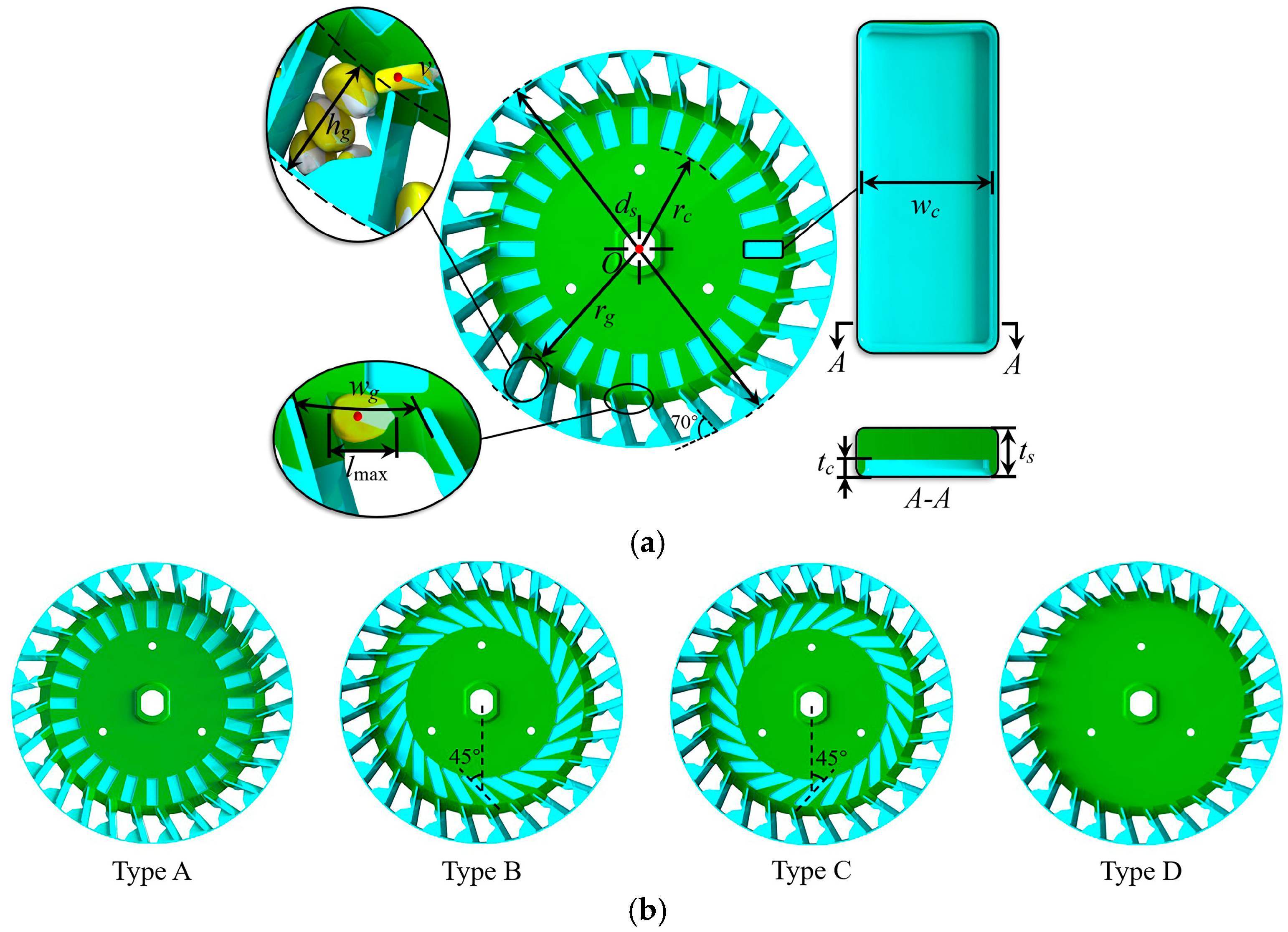
2.1. The Fundamental Structure and Principle

The quantitative precision filling seed-metering device mainly consists of the front shell, infeed groove, seed barrier, composite seeding tray, seed delivery board, guide wheel, seeding shaft, rear shell, seed-throwing port, and seed-protecting brush (Figure 1). The grooved teeth and seed grids are evenly distributed on the seeding tray.
The seed-metering device’s working principle can be divided into five processes: seed-filling, seed-clearing, seed-delivering, seed-guiding, and seed-throwing (Figure 2). To enhance the seed-filling effectiveness during high-speed seeding, the seed-metering device adopts the quantitative precision filling method, and the seed-filling process can be refined into two stages: initial quantitative filling (initial filling) and single-seed precision filling (precision filling). When the seeds enter the seed chamber from the front shell, they converge to the top of the infeed groove and are evenly and orderly dispersed into the seed grid under the driving effect of the grooved teeth, completing the initial filling. After the initial filling, the grid contains only the right amount of seeds (1 to 4 seeds), which does not block the opening of the seed dispenser due to an excessive amount of seeds. With the rotation of the seeding tray, the seeds in the grid slide rapidly relative to the seed dispenser. The first single seed to reach the opening of the seed dispenser quickly takes up the internal space of the seed dispenser, realizing the precision filling of a single seed. The other seeds continue to slip into the seed group as the seed grid passes through the seed-clearing area. The single seed continues to move to the seed-delivering area and slide into the compartment at the edge of the guide wheel. It is along the guiding curved surface of the rear shell to the seed-throwing port and then falls vertically [23]. The delivering, guiding, and throwing are completed sequentially.

2.2. Design and Analysis of Key Component Structure

2.2.1. Seed Barrier and Infeed Groove

The seed barrier is used to regulate the number of seeds supplied, preventing excessive seeds in the grid after initial filling from causing extrusion between the seeds and inhibiting the precision filling effect. The seed group can be classified into a static layer and a flow layer according to the movement characters of the seeds. The seeds in the flow layer continuously slide down to the top of the seed grid under the friction-driven action of the grooved teeth, and the seeds in the static layer gradually sink to fill the space. In order to subject the flow layer to sufficient friction-driven action from the grooved teeth, the inner wall of the infeed groove is provided with a 30° bevel for increasing the lateral pressure of the seeds, and its overall width bg is set at 13 mm, and the bottom width bo is set at 8.5 mm. The opening height of the seed barrier corresponds to the cross-sectional area of the flow layer and thus directly affects the initial filling stage. In order to reasonably determine the range of the opening height of the barrier ho, the mass center of a single seed in the seed supply process as the origin o, the motion direction as the x-axis, the seeding tray radial and vertical as the y-axis and z-axis to set up a spatial coordinate system and carry out the force analysis. The total force along the x-axis direction is the driving force Fx for the seed supply process (Figure 3a).
The force system diagram of a single seed in each coordinate plane is shown in Figure 3b. The normal force FN and tangential force FT between seeds are used to replace the mutual extrusion during seed supply, and the force equilibrium relationship of seeds in each plane is as follows:
F x = f 1 sin α c + G sin σ F T f 2 F n cos 30 ° = N F n sin 30 ° + f 1 cos α c = F N + F r + G cos σ
In Equation (1), f1 is the friction force of the grooved teeth on the seed (N), G is the gravity of the seed (N), f2 is the friction force of the guide groove on the seed (N), Fn is the support force on the seed (N), N is the reaction force of the grooved teeth on the seed (N), Fr is the centrifugal force on the seed (N), αc is the angle between the friction force of the grooved teeth and the seeding tray’s radial direction (°), and σ is the angle between the centrifugal force and gravity (°), where
G = m g F r = m r ω 2 f 1 = η N f 2 = μ F n
In Equation (2), m is the mass of the seed (kg), g is the acceleration of gravity (9.8 m·s−2), r is the radius at the position of the seed, m; ω is the angular speed of the seeding tray, rad·s−1; η is the sliding friction factor between the grooved teeth and the seed; and μ is the sliding friction factor between the guide groove and the seed.
The association of Equations (1) and (2) can be obtained:
F x = ( 3 sin α c 2 μ η 1 ) ( F N + m r ω 2 + m g cos σ ) η 1 + 3 cos α c + m g sin σ F T
From Equation (3), when the opening height of the seed barrier ho is reduced, the tangential extrusion of the seed along the motion trajectory is enhanced due to the expansion of the static layer and the reduction in the flow layer, resulting in an increase in the tangential force FT between the seeds and a decrease in the driving force Fx for seed supply, and the opposite will be increased. It can be inferred that the opening height of the seed barrier ho is positively related to the driving force Fx on the seed. To avoid the driving force of the seeds is not enough to cause the mobility of the seed group to be weakened, causing the seeds to be jammed at the opening of the seed barrier to produce a continuous leakage filling. The height of the opening of the seed barrier ho should be at least more as the maximum seed length lmax (14.1 mm). Meanwhile, to avoid the number of seeds supplied being too large, which will result in the seeds in the seed grid being filled up and extrusion, which will have a negative impact on the precision filling stage, and the driving force Fx of the seeds should not be too large. Therefore, the combination of theoretical analysis and pre-test sets the experimental range of the opening height of the seed barrier ho between 15 and 25 mm.

2.2.2. Seed Grid and Grooved Teeth

According to the “Agricultural Machinery Design Manual” and design experience, the diameter ds of the seeding tray is selected to be 220 mm and the thickness ts to be 3 mm [24,25]. Seed dispensers should not be spaced too close to each other. Otherwise, the width of the grid entrance will be too small, hindering the initial filling process. The seed dispensers must accommodate at least 1.5 times the maximum seed length of 21.1 mm between them. Thus, the range of values for the number of seed dispensers k is as follows:
k 2 π r a 21.1
where ra is the radius at the center of the internal space of the seed dispenser, and ra is taken as 97 mm in this study.
From Equation (4), the value of k cannot exceed 28.9. In order to ensure that the initial filling process of the seed-metering device is reliable and that the grid can accommodate the right amount of seeds, it can be determined that k is taken to be 27 after theoretical analysis and pre-testing.
When the number of seed dispensers is determined, the rotational speed n corresponding to the seed-metering device at different operating speeds can be further calculated as follows:
n = 10 , 000 V 6 z k
where V is the operating speed (km·h−1) and z is the maize planting spacing (25 cm).
Calculations indicate that when the operating speed of the seed-metering device is 20, 25, 30, and 35 r·min−1, respectively, the corresponding operating speeds are 8, 10, 12, and 14 km·h−1, respectively.
Seed grids and grooved tooth are the key structures of the composite seeding tray to realize the initial filling of maize seeds, and they are evenly distributed on the front side of the seeding tray. A seed grid receives a constant supply of seeds and needs carrying space within it (Figure 4a). To ensure that the seeds can enter the seed grid smoothly during the initial filling stage, the width wg at the entrance of the grid should be satisfied:
w g = 2 π r g k > Δ g l max
In Equation (6), rg is the radius of the grid top (mm), lmax is the maximum length of the seeds (mm), Δg is the experience extend coefficient (1.1–1.3).
The number of seed dispensers k is selected as 27, the maximum seed length lmax is measured at 14.1 mm, and Δg is taken as 1.3, which can be substituted into Equation (6) to obtain that the radius of the grid top rg should be greater than 79 mm. Meanwhile, considering that rg is too large will result in the height of the seed grid hg being too small, and the seed grid’s capacity is reduced, making it easy to make the seed overflow backward in the initial filling stage. Therefore, the radius of the grid top rg was set to 82 mm.
From Equation (3), the driving force Fx on the seed during seed supply is positively correlated with both the included angle αc and the sliding friction coefficient η. Since the αc and the η are determined by the shape and depth of the grooved teeth. When the driving force Fx is too large, it will enhance the seed group’s mobility, and the number of seeds supplied will be out of the appropriate range. While too small, it will lead to discontinuous seed supply and leakage filling. It can be inferred that the type and depth of grooved teeth significantly affect the initial filling stage, which in turn affects the precision filling stage.
In order to investigate the influence of the shape of the grooved teeth on the effect of seed-filling, the vertical grooved teeth, as the base type A and three additional grooved teeth structures were compared. Among them, the grooved teeth were inclined 45° to the left as type B, 45° to the right as type C, and the non-grooved tooth structure type D was used as an experimental control (Figure 4b). Meanwhile, it is important to ensure that the role and distribution of the grooved teeth structure are reasonable and easy to process and manufacture. The width of the grooved teeth wc should not be too large or too small. In this study, we took 8 mm, and the radius of the teeth top rc was 60 mm. The depth of the grooved teeth tc was taken as a parameter to be optimized, and its value was set to be in the range of 0.5–1.5 mm according to the the pre-test effect.

2.2.3. Seed Dispenser

The seed dispenser is located at the bottom of the seed grid and performs single-seed precision filling. The shape characteristics of maize seeds are important in determining their single-seed filling effect. According to the shape index of the scanned three-dimensional profile of “Zhengdan 958” maize seed, they are categorized into horse tooth, wedge, and sphere, with a ratio of 6:3:1 (Figure 5) [26].
Table 1 shows the triaxial dimensional ranges and average values of length l, width w, and thickness t for each type of seed. Because maize seeds have irregular shapes, significant size variations, and limited mobility within the seed group, conventional seed-filling methods often lead to the accumulation and compaction of seeds. As a result, effectively filling the seed becomes challenging [21,22,23].
To ensure the reliable effect of single-seed precision filling, the adaptability of the seed dispenser for single seeds should be enhanced. Its internal space is designed with irregular geometry, and the main structural parameters include hole height H, hole width W1, end width W2, hole depth L, hole inclination γ1, and hole declination γ2 (Figure 6). Based on the three different types of postures (side-standing, lying down, and standing) of different types of seeds (Figure 6), the ranges of some parameters can be identified as follows:
H ( l max , 1.3 l max ) W 1 ( w max cos γ 1 , 1.3 w max cos γ 1 ) W 2 ( 0.5 w max cos γ 1 , w max cos γ 1 ) L ( 0.5 l max , l max )
In order to exactly accommodate a single seed, the redundant structure should be removed from the seed dispenser as much as possible to avoid excess seed that it cannot clear. It is also important to ensure that the seed in the seed dispenser is sufficiently restrained to avoid it falling out during seed-clearing. The seed dispenser was designed with the bottom surface inclined at 30° to the rim of the seeding tray. According to the pre-test results combined with Equation (7), it can be determined that the structural parameters γ1, γ2, H, W1, W2, and L are taken as 30°, 20°, 15 mm, 11 mm, 5.5 mm, and 7.5 mm, respectively.

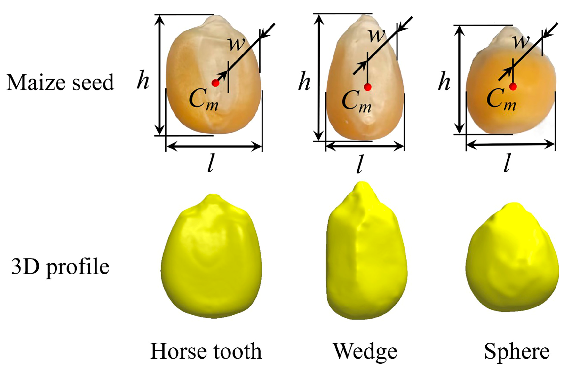
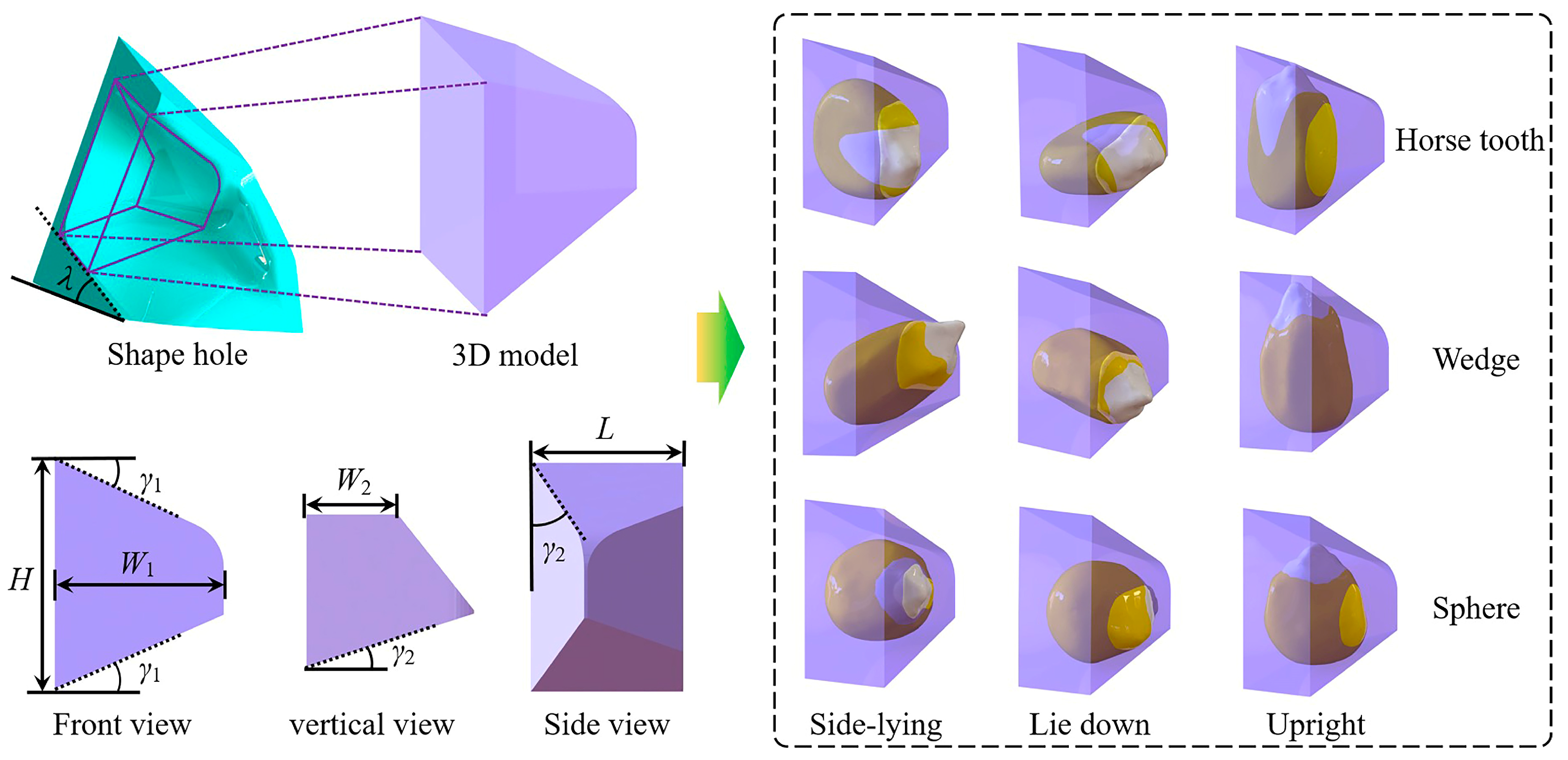
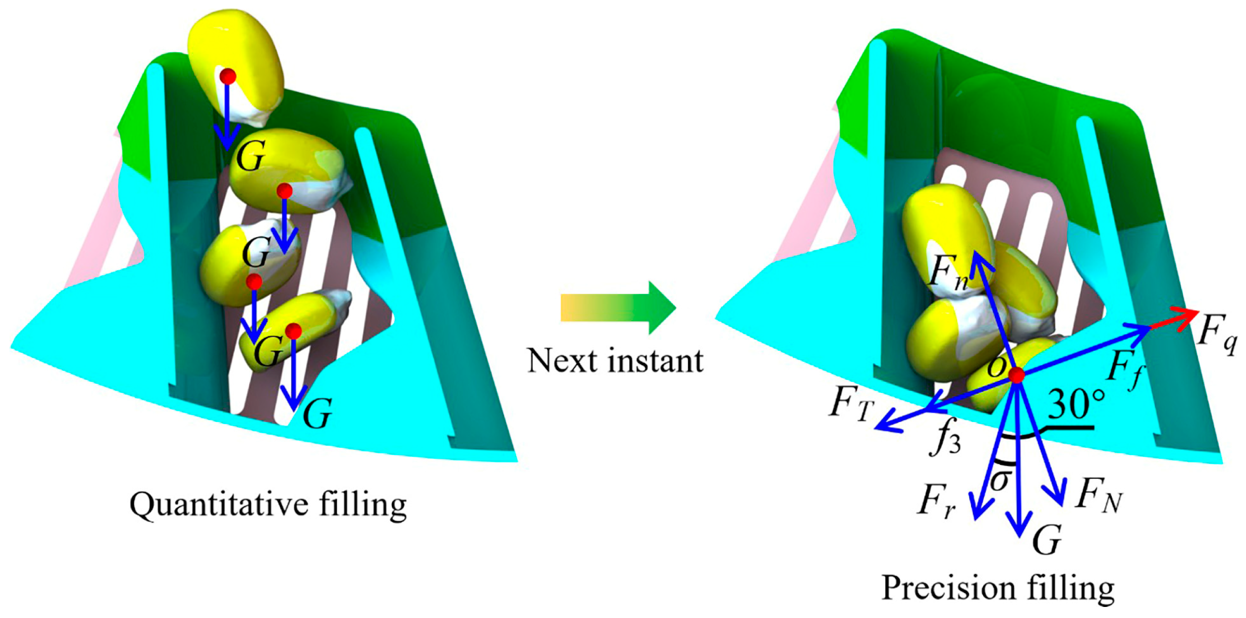
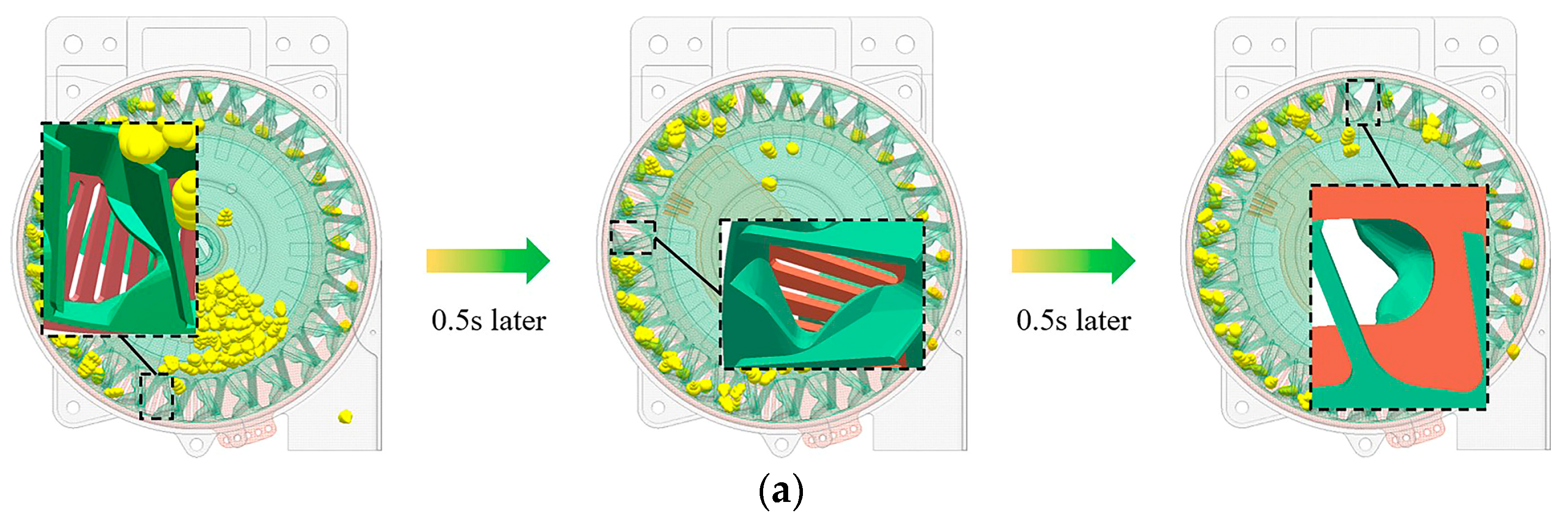
2.2.4. Analysis of Seed-Filling Process

In order to elucidate the enhancing principle of the quantitative precision filling method on the filling effect under high-speed conditions, as well as the relationship between the initial filling and the precision filling stages, it is necessary to analyze the forces on the seed during the overall filling process (Figure 7).
During the initial filling stage, seeds are continuously supplied to the top of the seed grid, and the seeds are accelerated down to the bottom of the grid by gravity alone. Subsequently, the seeds turn with the seeding tray and begin to migrate in the reverse direction relative to the filling port, entering the precision filling stage. At this time, the first single seed arriving at the seed-filling port, as the seed to be filled quickly seizes the internal space of the seed dispenser, and the rest of the seeds are stacked around it. The force state of the seed to be filled is analyzed to obtain the following:
F q = F f F r sin 30 ° G sin ( 30 ° σ ) f 3 F T F n = F N + G cos ( 30 ° σ ) + F r cos 30 ° f 3 = μ F n
In Equation (8), Fq is the filling force (N), Ff is the friction force on the seed by the seed delivery plate (N), and f3 is the friction force on the seed (N), where
F N = i = 1 j F N i F T = i = 1 j F T i F r = m r ω 2 G = m g
In Equation (9), j the number of surrounding seeds contacted by the seed to be filled, i is the ith seed contacted by the seed to be filled, FNi is the normal contact force between the seed to be filled and the ith contacted seed (N), FTi is the tangential contact force between the seed to be filled and the ith contacted seed (N).
The association of Equations (8) and (9) can be obtained:
F q = F g i = 1 j F T i μ i = 1 j F N i 1 + 3 μ 2 m r ω 2 m g 1 + μ 2 sin ( 30 ° σ + arctan μ )
From Equation (10), the filling force of the seed to be filled is negatively correlated with both the number of surrounding contact seeds and the magnitude of the contact force. In the seed grid, the number of seeds in front of the seed dispenser is moderate and loosely stacked. The seeds to be filled are less obstructed by the surrounding seeds, and the filling force is significantly increased, which helps the seeds enter the seed dispenser to realize single-seed filling. It is known that the type of the grooved teeth, the depth of the grooved teeth tc, the opening height of the seed barrier ho, and the rotational angular velocity of the seed plate ω all have a significant effect on the number of seeds in the seed grid after the initial filling, which in turn affects the overall seed-filling effect of the seed-metering device. Therefore, the above key factors will be explored in the following experiments.

2.3. Experiments and Methods

2.3.1. Simulation Experiment

To validate the theoretical analysis of the quantitative precision filling method and further optimize the high-speed operating performance of the seed-metering device. Firstly, EDEM2022 (Altair Engineering, Troy, NY, USA) software was applied to carry out the comparison experiment of the type of grooved teeth and evaluate the influence of different teeth types on seed supply capacity and seed-filling effect in the simulation post-processing module. Meanwhile, select the optimal structure according to the seed-metering performance of different tooth types. On this basis, a quadratic orthogonal optimization experiment was carried out to explore the influence law of experimental factors and their interactions on the seed-metering performance indices. Thereby determining the optimal parameter combinations of the seed-metering device [27].
The experiment related to seed-metering performance refers to GB/T 20865-2017 “no or little-tillage fertilizers-seeder”, and the rotational speed corresponding to different operating speeds of the seed-metering device was set according to the maize seeding plant spacing of 0.25 m [28]. After the seed-delivering process, only 1 seed was qualified, more than 1 seed was multiple, and no seed was leakage (Figure 8). The experiment collected seeds 250 times as a set of experimental samples, and each index (passing rate Y1, repetitive rate Y2, and miss rate Y3) was calculated as shown in Equation (11).
Y 1 = ( 0.4 n 1 ) % Y 2 = ( 0.4 n 2 ) % Y 3 = ( 0.4 n 3 ) %
In Equation (11), n1 is the number of qualified seeds, n2 is the number of multiple seeds, and n3 is the number of leakage seeds.

2.3.2. Simulation Modeling

The simulations modeled particle-to-particle and particle-to-geometry contacts using the Hertz–Mindlin (no-slip) contact model [29]. A 3D model of the seed-metering device was created using SolidWorks2021 (Dassault Systemes, Concord, MA, USA) and imported into EDEM2022. The particle model was established based on the actual seed shape and the range of triaxial dimensions using ball splicing. The triaxial dimensions of each type of seed were normally distributed in the ratio of 6:3:1 (Figure 9).
Since the movement characters of the seed in the flow layer directly influence the seed-metering device’s initial and precision filling stages, this determines the overall filling effect. Therefore, the simulation was mainly focused on the flow layer of the seed group, and the monitoring area of the seed group was used to quantify the impacts on the physical properties of the seeds. The material in the simulation process mainly involves the seeds and the seed-metering device. In the pre-study period, we performed parameter calibration experiments on the simulation model in Figure 9. The simulation physical parameters are set according to the model calibration results, as shown in Table 2 [23].

2.3.3. Bench Validation Experiment

The seed-metering performance was tested under the optimal combination parameters of the seed-metering device using the seeding performance test platform, and the simulation optimization results were verified. Secondly, the seed-metering performance of the seed-metering device was tested at different operating speeds of 8, 10, 12, and 14 km·h−1 (corresponding to rotational speeds of 20, 25, 30, and 35 r·min−1) and compared with the simulation test results under the same conditions in order to validate further the accuracy of the simulation model and the adaptability of the quantitative precision seed-filling method to the high-speed operating conditions.
The experiment was conducted according to the test method of a single-grain (maize, soybean) no-till planter in GB/T 20865-2017 “no or little-tillage fertilizers-seeder.” The experimental indices (grain spacing passing rate, grain spacing repetitive rate, and grain spacing miss rate) were counted, respectively. Each experiment was repeated three times, and the mean of each index was adopted as the experimental result.

2.3.4. Experiment Equipment and Materials

The test device consists of two parts: the JPS-12 seeding performance test platform and the information acquisition system. Among them, the JPS-12 seeding performance test platform mainly consists of a drive motor (rotational speed: 0–35 r·min−1), transmission device (sprocket, chain, drive shaft), and conveyor belt (belt speed: 0–14 km·h−1, with viscous oil on the surface for fixing the falling seeds). The information acquisition system consists of a high-speed photography (S-Series, Revealer, China), motion tracking software (Pro Analyst 8.3.1, Xcitex Inc, Cambridge, MA, USA), coordinate panels, and a fill light. Ungraded “Zhengdan 958” maize seeds (thousand kernel weight: 290.2 g, moisture content: 10.36%, angle of repose: 22.33°) were used for the experiment. The seed-metering device used in the experiment is a quantitative precision filling seed-metering device, and its key components are manufactured by a CNC four-axis numerical control machining center using aluminum alloy 6061 material (precision: ±0.01 mm) (Figure 10).

3. Results and Discussion

3.1. Simulation Comparison Experiment

In the simulation comparison experiment, the opening height of the seed barrier was set at 20 mm, and the depth of the grooved teeth was set at 1 mm. In order to ensure that the effect of high-speed operation is reliable, the experiment was carried out at an operation speed of 14 km·h−1 (corresponding to a rotational speed of 35 r·min−1).

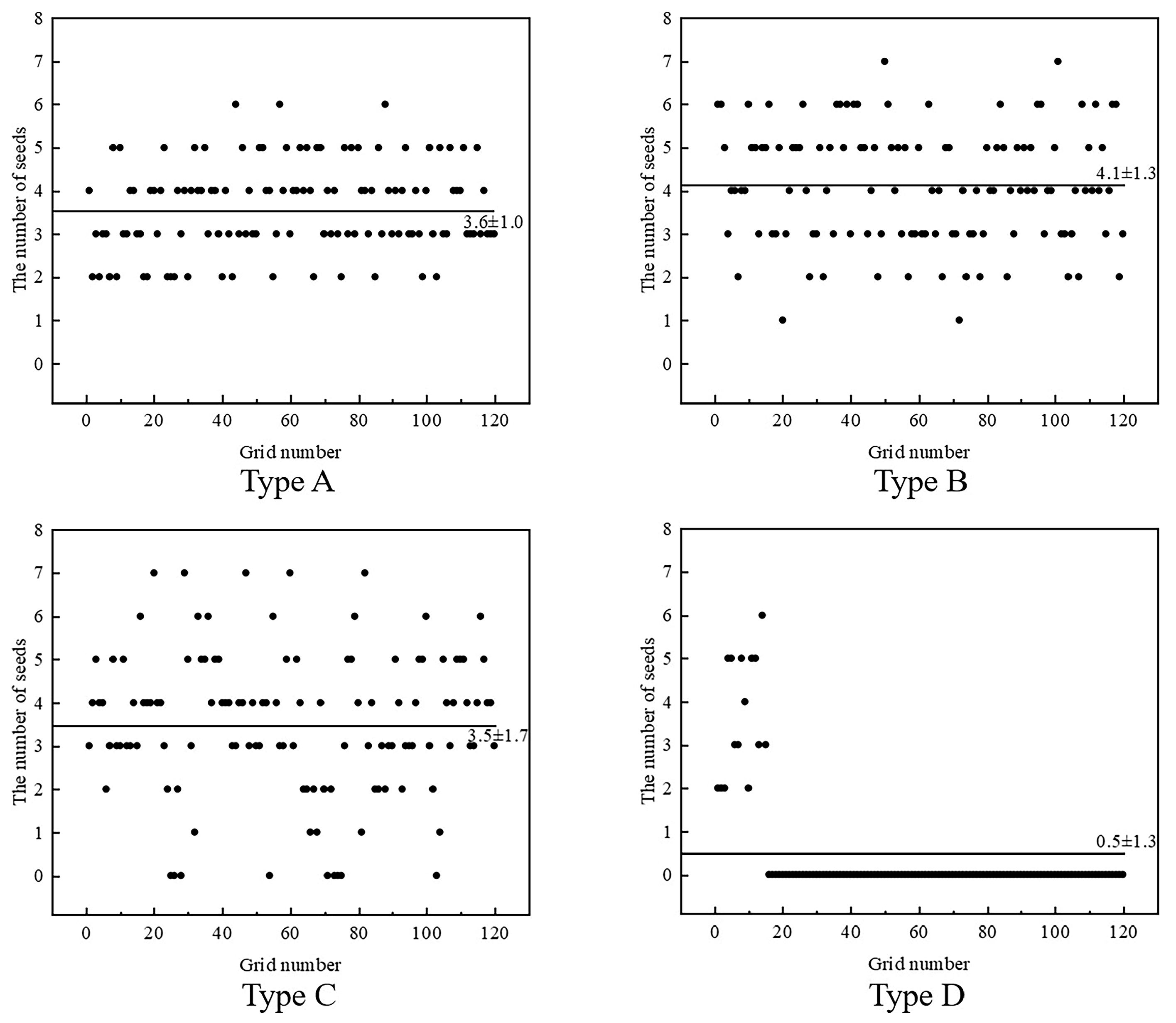
3.1.1. Influence of Grooved Teeth Type on Seed Supply Capacity

The preferred grooved teeth structure will enhance seed disturbance and increase seed dispersion, thereby driving the seeds in the flow layer in constant motion for continuous seed supply. To investigate the effect of different grooved teeth types on the seed supply capacity, the average kinetic energy of the seed group under the condition of different grooved teeth types was extracted in the simulation results (Figure 11a). The average kinetic energy of the seed group decreases from the flow layer to the static layer under the condition of the seeding tray with grooved teeth. Under the condition of non-grooved teeth, the whole seed group remains stationary. The results showed that the grooved tooth structure directly affected the disturbance effect on the seed group. The flow layer area is expanded when the seed group is more strongly disturbed. It will enhance seed mobility and help to promote a continuous supply of seeds.
The trend of the average kinetic energy of the flow layer with time for each type of grooved teeth is shown in Figure 11b. The average kinetic energy of type A fluctuates in the range of 2.6 × 10⁻⁵ J, and the average value is 1.32 × 10⁻⁵ J, both of which are the highest. The following are type B and type C, with fluctuation ranges of 2.3 × 10⁻⁵ J and 1.7 × 10⁻⁵ J, respectively, and mean values of 8.36 × 10⁻⁶ J and 8.1 × 10⁻⁶ J, respectively. Type D has the smallest fluctuation ranges and mean values of mean kinetic energies, which are 9.2 × 10⁻⁸ J and 1.47 × 10⁻⁹ J, respectively. It indicated that the type A grooved teeth had the most significant disturbance to the flow layer, the highest seed mobility, and the most potent seed supply capacity. The reason is that the direction of the friction force exerted on the seeds by the type A grooved teeth is almost the same as the direction of motion of the seeds, and the seeds flow faster, resulting in a more significant disturbance of the seed group, which has the highest average kinetic energy. The direction of the friction force exerted on the seed by the type B and C grooved teeth deviates from the direction of seed motion, and the seed is subjected to less driving force and slower flow speed, resulting in less disturbance of the seed group and a lower average kinetic energy.

3.1.2. Influence of Grooved Teeth Type on Seed-Filling Effect

The number and uniformity of the seed supply directly affect the initial and precision filling stages of the seed-metering device, which in turn determines the overall seed-filling effect. It is known from the analysis that the higher the number of seeds in the seed grid after the initial filling of the seeding tray, the more unfavorable it is to achieve the single-seed precision filling. In order to explore the reasonable range of the number of seeds after initial filling and to establish the accurate evaluation standard of the filling effect, the probabilities of effective filling of different numbers of seeds (1–8 seeds) after initial filling were first tested in the simulation post-processing. The results of seed-filling under each initial filling number condition were counted 120 times, and the single-seed filling rate (the ratio of the number of times a single-seed filling was realized in the precision filling stage to the number of times it was counted) was used as the final evaluation index. The single-seed rate under the different numbers of seeds (1–8 seeds) after initial filling is shown in Figure 12.
The single-seed filling rate shows a decreasing trend with an increase in the number of seeds after the initial filling. When the initial filling number of seeds did not exceed four grains, the single-seed filling rate declined gently, and the overall decline was relatively small, all remaining above 96%. The decrease in the single-seed filling rate increased when the number of initial filling seeds was more than four. When the number of initial filling seeds was raised from four to eight, the single-seed filling rate decreased by 9.2 percentage points. It can be analyzed that an increase in the number of seeds initially filled leads to an increase in the number of seeds accumulating around the seeds to be filled. The contact of the seeds to be filled with many seeds increases the filling hindrance, thus decreasing the probability that the seed dispenser will achieve single-seed filling.
The above analysis showed that the smaller the mean value of the number of seeds in the seed grid after the initial filling and the more concentrated the distribution, the higher the probability of realizing single-seed filling, which represents the better seed-filling effect of the seed-metering device, provided that the seed supply is continuous. To further measure the influence of different grooved teeth structures on the seed-filling effect, the mean and standard deviation (SD) of the number of seeds after initial filling was used as the evaluation standard, and the number of seeds after 120 consecutive initial fillings was counted. The influence of different grooved teeth types on the seed-filling effect is shown in Figure 13.
The mean values of the number of initial filling seeds corresponding to the type A, B, and C grooved teeth are 3.6, 4.1, and 3.5, respectively, with a relatively small overall difference. The number of initial filling seed’s SD corresponding to the type A grooved teeth is 1.0, the smallest, followed by type B and C with 1.3 and 1.7, respectively. It indicated that the number of initial filling seeds was more concentrated, and the seed-filling effect was more stable in the type A grooved teeth condition. The mean value of the initial filling number of seeds corresponding to the type D non-grooved teeth structure was 0.5, and the SD was 1.3. However, the interruption of seed supply in this condition led to the frequent occurrence of the number of initial filling seeds with 0, which resulted in successive leakage filling. It could not satisfy the demand for seed-filling. Therefore, type A grooved teeth had the best seed-filling effect, followed by types B and C.

3.2. Simulation Optimization Experiment

Based on the above results, the opening height of the seed barrier X1, the depth of the grooved teeth X2, and the operating speed (corresponding to the rotational speed of the seeding tray n) X3 were selected as the experimental factors. The passing rate Y1, the repetitive rate Y2, and the miss rate Y3 were selected as the experimental indices. A three-factor and three-level Box–Behnken orthogonal experiment was carried out [30]. The level coding of each experimental factor is shown in Table 3.
The results of the orthogonal experiment are shown in Table 4. To further analyze the influence patterns of experimental factors and their interrelationships on the seeding performance indices, the experimental results in Table 4 were analyzed by multiple regression fitting using Design Expert 8.0.6 (Stat-Ease Inc., Minneapolis, MN, USA) software, and a quadratic regression model between the factors and experimental indices was established.
The significance test results of the model are shown in Table 5. The results showed that the quadratic regression models for the passing rate Y1, the repetitive rate Y2, and the miss rate Y3 were all highly significant (p ≤ 0.01), and their lack of fit terms were not significant (p ≥ 0.05), indicating that the regression models had a high degree of fit. In the regression model of Y1, the influences of X1, X2, X1 X2, X12, X22, and X32 on the model are highly significant, the influence of X3 on the model is significant, the influences of the rest of the terms on the model are insignificant, and the significant degree of the factors is X1, X2, and X3 in descending order. In the regression model of Y2, the influences of X1, X1 X3, X12, X22, and X32 on the model are highly significant, the influence of X3 on the model is significant, the influences of the rest of the terms on the model are insignificant, and the significant degree of the factors is X1, X3, and X2 in descending order. In the regression model of Y3, the influences of X1, X2, X1 X2, X12, X22, and X32 on the model are highly significant, the influence of X3 on the model is significant, the influences of the rest of the terms on the model are insignificant, and the significant degree of the factors is X1, X2, and X3 in descending order.
The quadratic regression equation of the experimental factors and indices was established, and the non-significant terms were eliminated to obtain the final equation as Equation (12). The adjusted determination coefficients of the regression equations on Y1, Y2, and Y3 are 0.9927, 0.9303, and 0.9925, respectively. They are close to 1, meaning the regression models are highly significant and can be used for analysis and prediction. For visualizing and analyzing the interaction pattern between factors on the performance indices of seed-metering devices, response surfaces with significant interactions were established based on the quadratic regression equations between factors and indices (Figure 14).
Y 1 = 177.1 + 14.1 X 1 + 131.6 X 2 + 7.9 X 3 3.6 X 1 X 2 0.2 X 1 2 20.3 X 2 2 0.3 X 3 2 Y 2 = 31.8 1.3 X 1 3.0 X 3 + 0.06 X 1 X 3 + 0.02 X 1 2 + 2.19 X 2 2 + 0.08 X 3 2 Y 3 = 245.3 12.8 X 1 124.2 X 2 4.8 X 3 + 3.6 X 1 X 2 + 0.2 X 1 2 + 18.1 X 2 2 + 0.25 X 3 2
When the operating speed is constant, with the increase in the opening height of the seed barrier and the depth of the grooved teeth, the passing rate tends to increase and then decrease. When the opening height of the seed barrier is 19–23 mm and the depth of the grooved teeth is 0.9–1.3 mm, the passing rate is higher (Figure 14a). When the depth of the grooved teeth is constant, the repetitive rate shows a slightly decreasing and then increasing trend with the increase in the opening height of the seed barrier and the operating speed. The repetitive rate is lower when the opening height of the seed barrier is 15–19 mm and the operating speed is 10–12 km·h−1 (Figure 14b). When the operating speed is constant, the miss rate shows a decreasing and then increasing trend with the increase in the opening height of the seed barrier and the depth of the grooved teeth. When the opening height of the seed barrier is 19–23 mm and the depth of the grooved teeth is 0.9–1.3 mm, the miss rate is low (Figure 14c).
According to the changing trend of the qualified and miss rate, with the increase in the opening height of the seed barrier and the depth of the grooved teeth, the number of initial filling seeds gradually increased, and the continuity of the initial filling was enhanced. The frequency of leakage filling is significantly reduced due to the number of initial filling seeds being 0 (Figure 15a), resulting in a gradual decrease in the miss rate and a gradual increase in the passing rate. However, when the values of the opening height of the seed barrier and the depth of the groove teeth are too large, the number of initial filling seeds is too large, which leads to the enhancement of the extrusion and mutual inhibition effect between the seeds, and is not contribute to the single-seed precision filling. The frequency of leakage filling increases due to seed blocking the seed-filling port (Figure 15b), so the passing rate decreases, and the miss rate increases. Based on the changing trend of the repetitive rate, with the opening height of the seed barrier and the operating speed increase, the number of initial filling seeds gradually increases while the rotational speed of the seeding tray increases. The repetitive rate increases due to excessive seed centrifugal force, resulting in multiple seeds not being separated in time after simultaneous filling (Figure 15c).
The regression equations were optimally solved to obtain the optimal combination of operating parameters for the seed-metering device with the highest passing rate and the lowest multiple and leakage indices as the optimization objectives. The objective function and constraints are solved as follows:
max Y 1 ( X 1 , X 2 , X 3 ) min Y 2 ( X 1 , X 2 , X 3 ) min Y 3 ( X 1 , X 2 , X 3 ) s . t . 15   mm X 1 25   mm 0.5   mm X 2 1.5   mm 8   km h 1 X 3 14   km h 1
Under the conditions that the opening height of the seed barrier is 19.4 mm, the depth of the grooved teeth is 1.2 mm, and the operating speed is 10.7 km·h−1, the passing rate, the repetitive rate and the miss rate reach 96.6%, 1.1%, and 2.2%, respectively, and the seed-metering performance reaches the optimization.

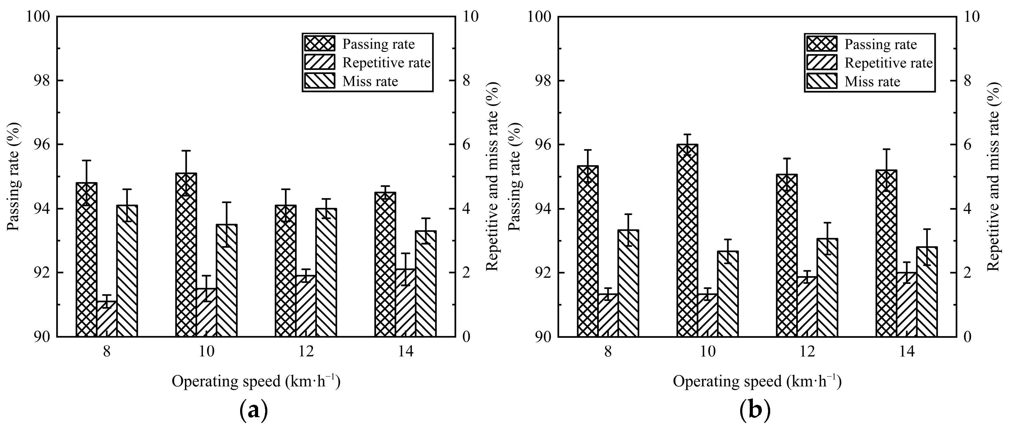
3.3. Results of the Bench Validation Experiment

The results of the performance validation experiment of the seed-metering device are shown in Figure 16. Under the optimal operating parameters of the quantitative precision filling seed-metering device with the opening height of the seed barrier of 19.4 mm, the depth of the grooved teeth of 1.2 mm, and the operating speed of 10.7 km·h−1, the passing rate, the repetitive rate, and the miss rate reached 95.1%, 1.6%, and 3.3%, respectively. In the range of operating speed 8–14 km·h−1, the qualitative precision filling seed-metering device’s passing rate is higher than 94.1%, the repetitive rate is lower than 2.3%, and the miss rate is lower than 3.7%, which meets the requirements of high-speed precision seeding of maize.
In the simulation, in the operating speed range from 8 to 14 km·h−1, the passing rate of the seed-metering device is higher than 95.1%, the repetitive rate is lower than 2.0%, and the miss rate is lower than 3.3%. Comparing the bench test results, the simulation results of the seed-metering device under optimal working parameters and the conditions of 8–14 km·h−1 are consistent with the bench test results, and the error is low. The analysis showed that the reasons could lead to errors in the seeding performance test results due to machining and assembly errors in the physical conditions of the seed-metering device, as well as the significant differences between the actual seed shape and the simulation model. However, they are all within a reasonable range. Therefore, the simulation optimization results were highly accurate.
In Figure 16, when the operating speed is maintained in the range of 8 to 14 km·h−1, the passing rate of the seed-metering device is between 94.1% and 95.1%. The overall passing rate is relatively stable, with the increase in operating speed showing a slightly fluctuating trend of increasing and then decreasing. However, the overall difference is slight, without significant abrupt changes. It is indicated that by limiting the number of seeds in front of the filling port, the quantitative precision filling method can eliminate the centrifugal extrusion and mutual restraint effect of the seed groups triggered by high speed and realize the single-seed precision filling, which can effectively enhance the adaptability of high-speed operating of mechanical precision metering devices.

4. Conclusions

(1) This study proposed a novel seed-filling method to enhance the seed-filling stability of mechanical precision metering devices under high-speed operating conditions. This method effectively limited the accumulation of seeds in front of the filling port while improving the effect of single-seed precision filling. Additionally, a quantitative precision filling seed-metering device for maize was also presented. The key parameters influencing the seed-filling effect and their value ranges were determined by completing the structural parameters design of key components and the theoretical analysis of the quantitative precision filling method.
(2) The simulation comparison experiment of different grooved teeth types showed that the seed-metering device has a more continuous seed supply, better seed-filling effect, and higher seed-metering performance under type A grooved teeth. A Box–Behnken orthogonal simulation experiment was carried out based on the structure of type A grooved teeth. The experimental results showed that when the opening height of the seed barrier was 19.4 mm, the depth of the grooved teeth was 1.2 mm, and the operating speed was 10.7 km·h−1, the seed-metering performance of the seed-metering device reached the optimum. In this condition, the passing, repetitive, and miss rates reached 96.6%, 1.1%, and 2.2%, respectively.
(3) The performance validation experiment showed that the passing rate, repetitive rate, and miss rate under the optimal parameters of the seed-metering device reached 95.1%, 1.6%, and 3.3%, respectively, consistent with the simulation results. In the speed range of 8 to 14 km·h−1, the quantitative precision filling seed-metering device’s passing rate was higher than 94.1%, the repetitive rate was lower than 2.3%, and the miss rate was lower than 3.7%, which meets the technical requirements of high-speed seeding operation of maize. This study proved that the mechanical precision metering device adopted by the quantitative precision filling method can effectively enhance the seed-filling effect under high-speed operating conditions. However, the actual application of this method has yet to be further proven. In order to realize this method more accurately, how to ensure a uniform and continuous seed supply remains a significant challenge for future research.

Author Contributions

Conceptualization, J.D. and X.G.; methodology, J.D. and Y.Z.; software, J.D.; validation, J.D. and Y.Z.; formal analysis, J.W.; investigation, J.D. and Y.Z.; resources, X.G.; data curation, J.W.; writing—original draft preparation, J.D.; writing—review and editing, J.D.; visualization, J.D.; supervision, X.G.; project administration, X.G.; funding acquisition, X.G. All authors have read and agreed to the published version of the manuscript.

Funding

This research was funded by the National Natural Science Foundation of China, grant number 52205283, the Opening Fund of the National Key Laboratory of Agricultural Equipment Technology, grant number NKL-2023–008, and the Fundamental Research Funds for the Central Universities, grant number YDZX2025011.

Institutional Review Board Statement

Not applicable.

Data Availability Statement

The raw data supporting the conclusions of this article will be made available by the authors on request.

Acknowledgments

Thanks to the Revealer brand for providing high-speed photographic equipment support.

Conflicts of Interest

The authors declare no conflicts of interest.

References

  1. Anantachar, M.; Kumar, P.G.V.; Guruswamy, T. Neural network prediction of performance parameters of an inclined plate seed metering device and its reverse mapping for the determination of optimum design and operational parameters. Comput. Electron. Agric. 2010, 72, 87–98. [Google Scholar] [CrossRef]
  2. Dzvene, A.R.; Tesfuhuney, W.A.; Walker, S.; Ceronio, G. Optimizing the planting time and stand density of sunn hemp intercropping for biomass productivity and competitiveness in a maize-based system. Field Crops Res. 2023, 304, 109179. [Google Scholar] [CrossRef]
  3. Cay, A.; Kocabiyik, H.; May, S. Development of an electro-mechanic control system for seed-metering unit of single seed corn planters Part II: Field performance. Comput. Electron. Agric. 2018, 145, 11–17. [Google Scholar] [CrossRef]
  4. Pareek, C.M.; Tewari, V.K.; Machavaram, R.; Nare, B. Optimizing the seed-cell filling performance of an inclined plate seed metering device using integrated ANN-PSO approach. Artif. Intell. Agric. 2021, 5, 1–12. [Google Scholar] [CrossRef]
  5. Wang, J.; Tang, H.; Guan, R.; Li, X.; Bai, H.; Tian, L. Optimization design and experiment on clamping static and dynamic finger-spoon maize precision seed metering device. Trans. Chin. Soc. Agric. Mach. 2017, 48, 48–57. [Google Scholar] [CrossRef]
  6. Guzman, L.J.; Chen, Y.; Landry, H. Discrete element modeling of seed metering as affected by roller speed and damping coefficient. Trans. ASABE 2020, 63, 189–198. [Google Scholar] [CrossRef]
  7. Karayel, D.; Wiesehoff, M.; Özmerzi, A.; Müller, J. Laboratory measurement of seed drill seed spacing and velocity of fall of seeds using high-speed camera system. Comput. Electron. Agric. 2006, 50, 89–96. [Google Scholar] [CrossRef]
  8. Xue, P.; Xia, X.; Gao, P.; Ren, D.; Hao, Y.; Zheng, Z.; Zhang, J.; Zhu, R.; Hu, B.; Huang, Y. Double-Setting seed-metering device for precision planting of soybean at high Speeds. Trans. ASABE 2019, 62, 187–196. [Google Scholar] [CrossRef]
  9. BARUT, Z.B. Effect of different operating parameters on seed holding in the single seed metering unit of a pneumatic planter. Turk. J. Agric. For. 2004, 28, 435–441. [Google Scholar]
  10. Virk, S.S.; Porter, W.M.; Fulton, J.P.; Pate, G.L. Field validation of seed meter performance at varying seeding rates and ground speeds. Appl. Eng. Agric. 2019, 35, 937–948. [Google Scholar] [CrossRef]
  11. Yang, L.; Yan, B.; Cui, T.; Yu, Y.; He, X.; Liu, Q.; Liang, Z.; Yin, X.; Zhang, D. Global overview of research progress and development of precision maize planters. Int. J. Agric. Biol. Eng. 2016, 9, 9–26. [Google Scholar] [CrossRef]
  12. Shen, H.; Zhang, J.; Chen, X.; Dong, J.; Huang, Y.; Shi, J. Development of a guiding-groove precision metering device for high-speed planting of soybean. Trans. ASABE 2021, 64, 1113–1122. [Google Scholar] [CrossRef]
  13. Liu, C.; Du, X.; Zhang, F.; Ma, T.; Zhang, H.; Li, Y. Design and test of cone diversion type horizontal plate wheat precision seed-metering device. Trans. Chin. Soc. Agric. Mach. 2018, 49, 56–65. [Google Scholar] [CrossRef]
  14. Du, X.; Liu, C.; Jiang, M.; Zhang, F.; Yuan, H.; Yang, H. Design and experiment of self-disturbance inner-filling cell wheel maize precision seed-metering device. Trans. Chin. Soc. Agric. Eng. 2019, 35, 23–34. [Google Scholar] [CrossRef]
  15. Kinze. Finger Pick-Up Meter. Available online: https://www.kinze.com/planter-performance/meters/finger-pick-up-meter/ (accessed on 18 June 2025).
  16. Embreparts. Plantsystem MAX. Available online: https://plantsystem.com.br/produto/pipoqueira (accessed on 18 June 2025).
  17. Singh, R.C.; Singh, G.; Saraswat, D.C. Optimisation of design and operational parameters of a pneumatic seed metering device for planting cottonseeds. Biosyst. Eng. 2005, 92, 429–438. [Google Scholar] [CrossRef]
  18. Jia, H.; Chen, Y.; Zhao, J.; Wang, J.; Guo, M.; Zhuang, X. Design and experiment of pneumatic-mechanical combined precision metering device for soybean. Trans. Chin. Soc. Agric. Mach. 2018, 49, 75–86, 139. [Google Scholar] [CrossRef]
  19. Liu, Y.; Lin, J.; Li, B.; Ma, T.; Song, J.; Tian, Y. Design and experiment of horizontal disc seed metering device for maize seeder. Trans. Chin. Soc. Agric. Eng. 2017, 33, 37–46. [Google Scholar] [CrossRef]
  20. Maleki, M.R.; Mouazen, A.M.; De Ketelaere, B.; De Baerdemaeker, J. A New index for seed distribution uniformity evaluation of grain drills. Biosyst. Eng. 2006, 94, 471–475. [Google Scholar] [CrossRef]
  21. Li, C.; Cui, T.; Zhang, D.; Yang, L.; He, X.; Jing, M.; Dong, J.; Wu, D.; Wang, Z. Design shaped hole inserts by simulating and analysing the high-speed filling posture of maize seed particles. Biosyst. Eng. 2023, 232, 29–50. [Google Scholar] [CrossRef]
  22. Yang, L.; Li, Z.; Zhang, D.; Li, C.; Cui, T.; He, X. Design and test of the T-shaped hole of centrifugal high-speed maize precision seed metering device. Trans. Chin. Soc. Agric. Eng. 2024, 40, 50–60. [Google Scholar] [CrossRef]
  23. Dong, J.; Zhang, S.; Zheng, Z.; Wu, J.; Huang, Y.; Gao, X. Development of a novel perforated type precision metering device for efficient and cleaner production of maize. J. Clean. Prod. 2024, 443, 140928. [Google Scholar] [CrossRef]
  24. Chinese Academy of Agricultural Mechanization Sciences. Agricultural Machinery Design Manual; China Agricultural Science and Technology Press: Beijing, China, 2007. [Google Scholar]
  25. St Jack, D.; Hesterman, D.C.; Guzzomi, A.L. Precision metering of Santalum spicatum (Australian Sandalwood) seeds. Biosyst. Eng. 2013, 115, 171–183. [Google Scholar] [CrossRef]
  26. Chen, Z.; Yu, J.; Xue, D.; Wang, Y.; Zhang, Q.; Ren, L. An approach to and validation of maize-seed-assembly modelling based on the discrete element method. Powder Technol. 2018, 328, 167–183. [Google Scholar] [CrossRef]
  27. Li, Z.; He, S.; Zhong, J.; Han, J.; Chen, Y.; Song, Y. Parameter optimization and experiment of the disturbance pneumatic plate hole metering device for rapeseed. Trans. Chin. Soc. Agric. Eng. 2021, 37, 1–11. [Google Scholar] [CrossRef]
  28. GB/T20865-2017; No or Little-Tillage Fertilizers-Seeder. Standards Press of China: Beijing, China, 2018.
  29. Adilet, S.; Zhao, J.; Sayakhat, N.; Chen, J.; Nikolay, Z.; Bu, L.; Sugirbayeva, Z.; Hu, G.; Marat, M.; Wang, Z. Calibration strategy to determine the interaction properties of fertilizer particles using two laboratory tests and DEM. Agriculture 2021, 11, 592. [Google Scholar] [CrossRef]
  30. Zhao, X.; Liu, R.; Liu, F.; Bai, H.; Dong, W. Research on the cluster hole effect and performance testing of air-suction quinoa seed metering device. Agriculture 2024, 14, 1391. [Google Scholar] [CrossRef]
Figure 1. The structure diagram of device. 1. Front shell, 2. infeed groove, 3. seed barrier, 4. composite seeding tray, 5. seed delivery board, 6. guide wheel, 7. seeding shaft, 8. rear shell, 9. seed-throwing port, 10. seed-protecting brush.
Agriculture 15 01517 g001
Figure 2. The working principle of device. 1. Grooved tooth, 2. seed grid, 3. seed dispenser, 4. guiding curved surface. I. Filling process, II. clearing process, III. delivering process, IV. guidingprocess, V. throwing process.
Agriculture 15 01517 g002
Figure 3. The structure diagram of seed barrier and infeed groove. (a) The driving force for the seed supply process. (b) The force system diagram of a single seed in each coordinate plane.
Agriculture 15 01517 g003
Figure 4. The structure diagram of seed grid and grooved teeth. (a) The parametric design of the composite seeding tray. (b) The different types of grooved teeth.
Agriculture 15 01517 g004
Figure 5. The different types of maize seeds.
Agriculture 15 01517 g005
Figure 6. The structure diagram of seed dispenser.
Agriculture 15 01517 g006
Figure 7. The analysis of seed-filling process.
Agriculture 15 01517 g007
Figure 8. Simulation evaluation indices.
Agriculture 15 01517 g008
Figure 9. Simulation model.
Agriculture 15 01517 g009
Figure 10. Bench testing environment.
Agriculture 15 01517 g010
Figure 11. The influence of grooved teeth type on seed supply capacity. (a) The average kinetic energy of the seed group. (b) The trend of the average kinetic energy of the flow layer.
Agriculture 15 01517 g011
Figure 12. The single-seed rate under the different numbers of seeds after initial filling.
Agriculture 15 01517 g012
Figure 13. The influence of different grooved teeth types on the seed-filling effect.
Agriculture 15 01517 g013
Figure 14. The response surface with significant interaction. (a) Y1 = f (X1, X2), (b) Y2 = f (X1, X3), (c) Y3 = f (X1, X2).
Agriculture 15 01517 g014
Figure 15. Simulation analysis of multiple and leakage seeding. (a) Leakage filling caused by the number of initial filling seeds being 0. (b) Leakage filling caused by seed blocking the seed-filling port. (c) Multiple filling caused by simultaneous filling.
Agriculture 15 01517 g015aAgriculture 15 01517 g015b
Figure 16. The results of the performance validation experiment. (a) Bench test results. (b) Simulation test results.
Agriculture 15 01517 g016
Table 1. Triaxial dimensions of maize seeds.
Triaxial DimensionsHorse ToothWedgeSphere
l (mm)10.8–13.511.0–14.06.7–10.5
w (mm)7.5–10.75.9–9.57.4–10.9
t (mm)3.8–6.34.3–8.45.7–10.7
Table 2. Simulation parameters.
ParametersMaize SeedSeed-Metering Device
Density (kg·m−3)11972700
Poisson’s ratio0.40.33
Shear modulus (Pa)1.37 × 1082.7 × 1010
Restitution coefficient0.1820.62
Static friction coefficient0.070.3
Sliding friction coefficient0.020.09
Table 3. Factor level coding.
CodesOpening Height of the Seed Barrier
X1 (mm)
The Depth of the Grooved Teeth
X2 (mm)
Operating Speed
X3 (km·h−1)
1251.514 (35 r·min−1)
0201.011 (27.5 r·min−1)
−1150.58 (20 r·min−1)
Table 4. Orthogonal experimental results.
No.X1 (mm)X2 (mm)X3 (km·h−1)Y1 (%)Y2 (%)Y3 (%)
1150.51160.90.938.2
2250.51194.13.12.8
3151.51193.30.95.8
4251.51190.13.76.2
5151.0878.8219.2
6251.0893.12.14.8
7151.01480.10.819.1
8251.01494.84.40.8
9200.58802.117.9
10201.5893.124.9
11200.51482.92.115.0
12201.51493.13.23.7
13201.01196.10.93.0
14201.01195.61.52.9
15201.01194.90.84.3
16201.01194.81.33.9
17201.01195.20.93.9
Table 5. Significance analysis.
SourcePassing Rate Y1 (%)Repetitive Rate Y2 (%)Miss Rate Y3 (%)
FpFpFp
Model243.52<0.0001 **24.730.0002 **236.35<0.0001 **
X1673.05<0.0001 **110.29<0.0001 **811.41<0.0001 **
X2516.80<0.0001 **3.730.0947502.94<0.0001 **
X36.730.0357 *7.710.0274 *11.900.0107 *
X1 X2512.36<0.0001 **1.050.3398453.79<0.0001 **
X1 X30.0620.810735.700.0006 **5.390.0533
X2 X33.250.11434.200.07971.020.3454
X12207.72<0.0001 **13.400.0081 **156.63<0.0001 **
X22167.58<0.0001 **14.710.0064 **122.10<0.0001 **
X3257.550.0001 **25.620.0015 **30.190.0009 **
Lack of fit3.920.10990.840.53763.000.1580
** indicates highly significant, p-value < 0.01; * indicates significant, 0.01 < p-value < 0.05.
Disclaimer/Publisher’s Note: The statements, opinions and data contained in all publications are solely those of the individual author(s) and contributor(s) and not of MDPI and/or the editor(s). MDPI and/or the editor(s) disclaim responsibility for any injury to people or property resulting from any ideas, methods, instructions or products referred to in the content.

