Article

Design and Numerical Simulation of a Device for Film–Soil Vibrating Conveying and Separation Based on DEM–MBD Coupling

1
College of Electromechanical Engineering, Xinjiang Agricultural University, Urumqi 830052, China
2
Autonomous Region Agricultural Machinery Product Quality Supervision and Management Station, Urumqi 830091, China
3
Institute of Agricultural Mechanization, Xinjiang Academy of Agricultural Sciences, Urumqi 830091, China
*
Author to whom correspondence should be addressed.
Agriculture 2025, 15(14), 1501; https://doi.org/10.3390/agriculture15141501
Submission received: 12 June 2025 / Revised: 7 July 2025 / Accepted: 10 July 2025 / Published: 12 July 2025
(This article belongs to the Section Agricultural Technology)

Abstract

To address the issue of poor film–soil separation in traditional subsoil residual film recovery machines, which leads to recovered film containing excessive soil, a film–soil conveying and separation device was designed. By establishing a mechanical model for the balanced conveyance of the film–soil composite, the range of conveyor chain inclination angles enabling stable transport was determined. Using RecurDyn 2023 simulation software, a sensitivity analysis was conducted on the effects of vibrating wheel speed, vibrating wheel mounting distance, and conveyor chain inclination angle on vibration characteristics. This analysis revealed that vibrating wheel speed and mounting distance have a significant impact on the vibrating mechanism. Based on the DEM–MBD (Discrete Element Method—Multi-Body Dynamics) coupling approach, a discrete element simulation model was built for the film–soil vibrating conveyor device, residual film, and soil. Using the primary conveyor chain speed, vibrating wheel speed, and mounting distance as experimental factors, and soil content rate and film leakage rate as experimental indicators, single-factor tests and a three-factor, five-level orthogonal rotational composite design test were performed. The results showed that, at a primary conveyor chain speed of 1.61 m/s, a vibrating wheel speed of 186.2 r/min, and a mounting distance of 688.2 mm, the soil content rate was 18.11% and the film leakage rate was 7.61%. The film–soil conveying and separation process was also analyzed via simulation. Field validation tests using the optimal parameter combination yielded relative errors of 3.43% and 5.51%, respectively, demonstrating effective film–soil separation. This research provides a theoretical foundation and equipment support for addressing residual film pollution in the cultivated layer of Xinjiang region.

1. Introduction

Plastic film mulching technology, renowned for its moisture conservation and yield enhancement benefits, is extensively employed in arid crop-growing regions such as Xinjiang, China [1]. Currently, the mulched area in Xinjiang exceeds 3.67 million hectares with annual film consumption reaching 2.5 × 10⁵ metric tons—representing massive utilization volumes [2]. However, incomplete recovery leads to progressive accumulation in soils, severely impeding subsequent crop growth. Farmlands with residual film unrecovered for over a decade persist in Xinjiang. Statistics indicate an average residual film accumulation of approximately 260 kg/ha in Xinjiang’s croplands, exhibiting an increasing trend [3].
This residual film significantly deteriorates soil physicochemical properties and reduces crop yields, undermining agricultural sustainability [4,5,6]. When retained in tillage layers, the film undergoes mechanical degradation due to erosion from soil, stones, and irrigation [7]. Its flexible nature promotes tight bonding with soil, resulting in random horizontal layering or aggregation within the tillage layer that hampers film–soil separation [8]. Furthermore, fragmented distribution patterns cause substantial film loss during mechanical recovery [9,10].
Regarding research on subsurface residual film recovery equipment, farmlands in other countries primarily utilize high-reliability, high-strength plastic films. Post-harvest, these films can be recovered largely intact, effectively preventing residual film accumulation within the tillage layer. Consequently, global research specifically focused on recovering subsurface residual film remains limited [11]. In contrast, Chinese scholars pioneered research in this field during the 1980s. To date, a diverse range of subsurface residual film recovery machinery has been developed [12,13,14]. To address distinct technical challenges, researchers have engineered various film–soil separation mechanisms, including Zhang et al. who designed a counter-flow separation device exploiting differential frictional properties between residual film and soil clods on conveyor belts, directing film to collection boxes while soil falls back to fields via gravity [15]. Guo et al. proposed a comb-lifting/pneumatic-stripping method to resolve high soil impurity issues, where combs elevate subsurface film before suction mechanisms transfer it to collection chambers [16]. Luo et al. developed a chain-screening recovery machine: digging loosens soil, then chain-mounted hooks extract film from the tillage layer for separation [17]. Zhang et al. employed vibration for preliminary film–soil segregation, followed by pneumatic conveyance to collection bins via blowers [18].
In summary, current conventional residual film recovery processes face three persistent challenges; small soil clods adhering to film surfaces result in high soil content in recovered material. Extraction via spiked-chain mechanisms induces tearing during “hooking-and-pulling” operations. Pneumatic separation systems ingest fine soil particles into film collection chambers, thereby increasing power consumption [19].
With the continuous advancement of computer technology, DEM–MBD coupled simulation provides an efficient, flexible, and visual research method for studying the contact and motion processes between agricultural machinery components and soil. Current research has employed DEM–MBD coupled simulation to study operations such as straw clearing and soil tillage. Zhang et al. optimized the reliability of soil-engaging components based on structural measurements to model the interaction between corn stalks and soil [20]. Zeng et al. utilized DEM–MBD coupled simulation to obtain the optimal parameter combination for a rotary trenching cutter assembly and investigated its soil disturbance mechanism [21]. Yang et al. established a soil–tool interaction simulation model using DEM–MBD coupled simulation technology, providing a basis for the structural simulation and optimization of tillage tools [22]. However, existing research rarely involves simulating material conveying and separation under the coupled action of conveying and vibration. Furthermore, validation tests are often based on soil bin experiments under specific conditions rather than actual field operations, which may lead to discrepancies between the analysis results and real field behavior.
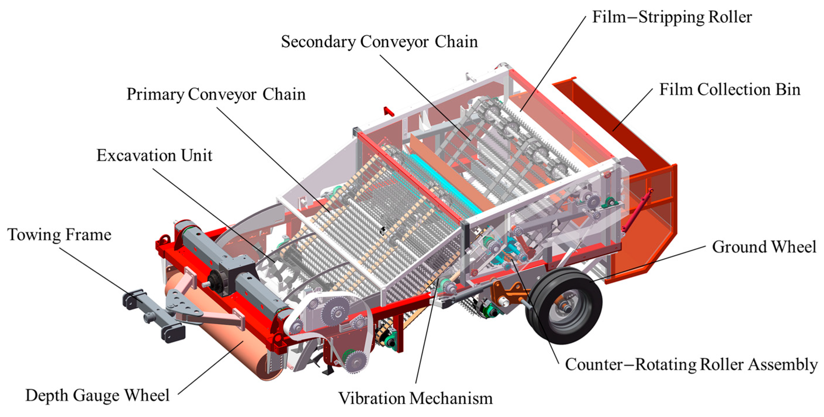
Addressing the operational requirements for residual film recovery in China’s tillage-layer soils, this study develops a novel residual film recovery machine for Xinjiang cotton fields. The machine features an innovative three-stage separation mechanism: (1) primary vibratory conveyance, (2) counter-rotating roller compaction, and (3) secondary conveyance.
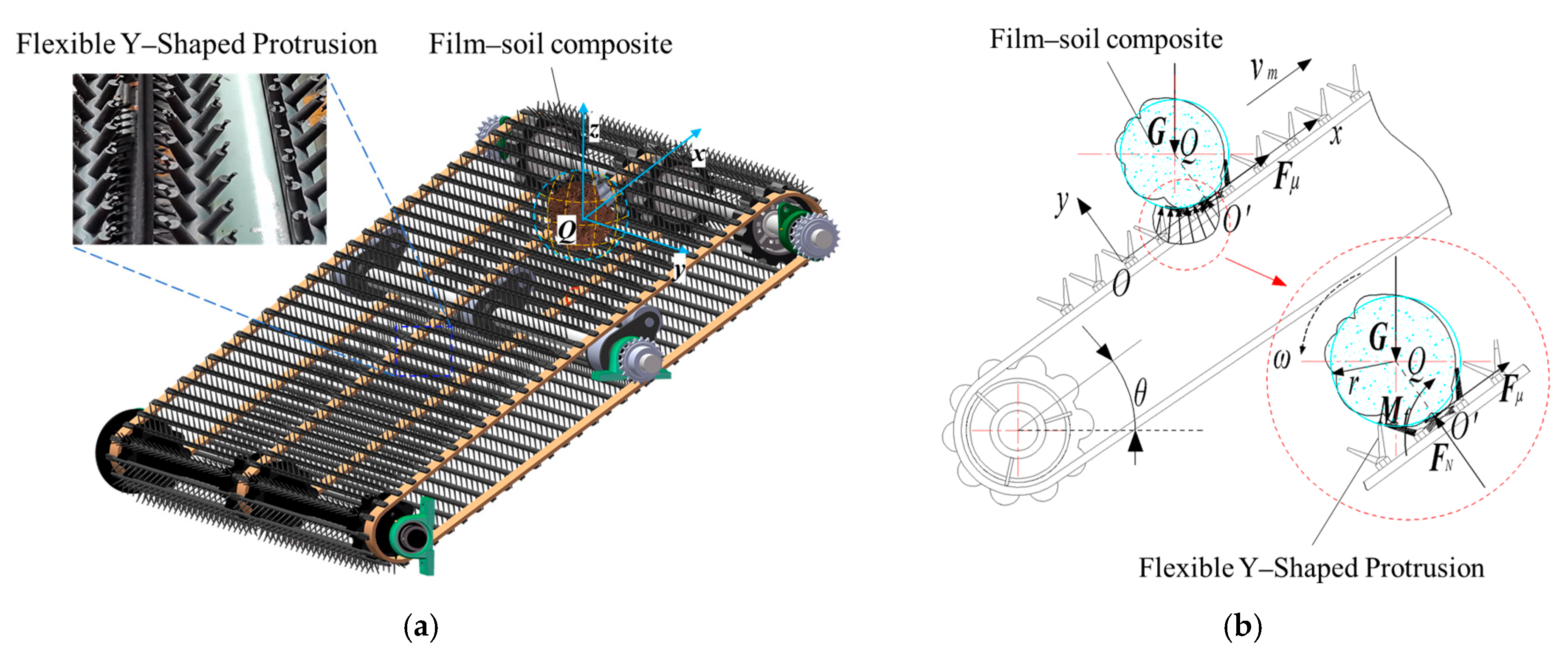
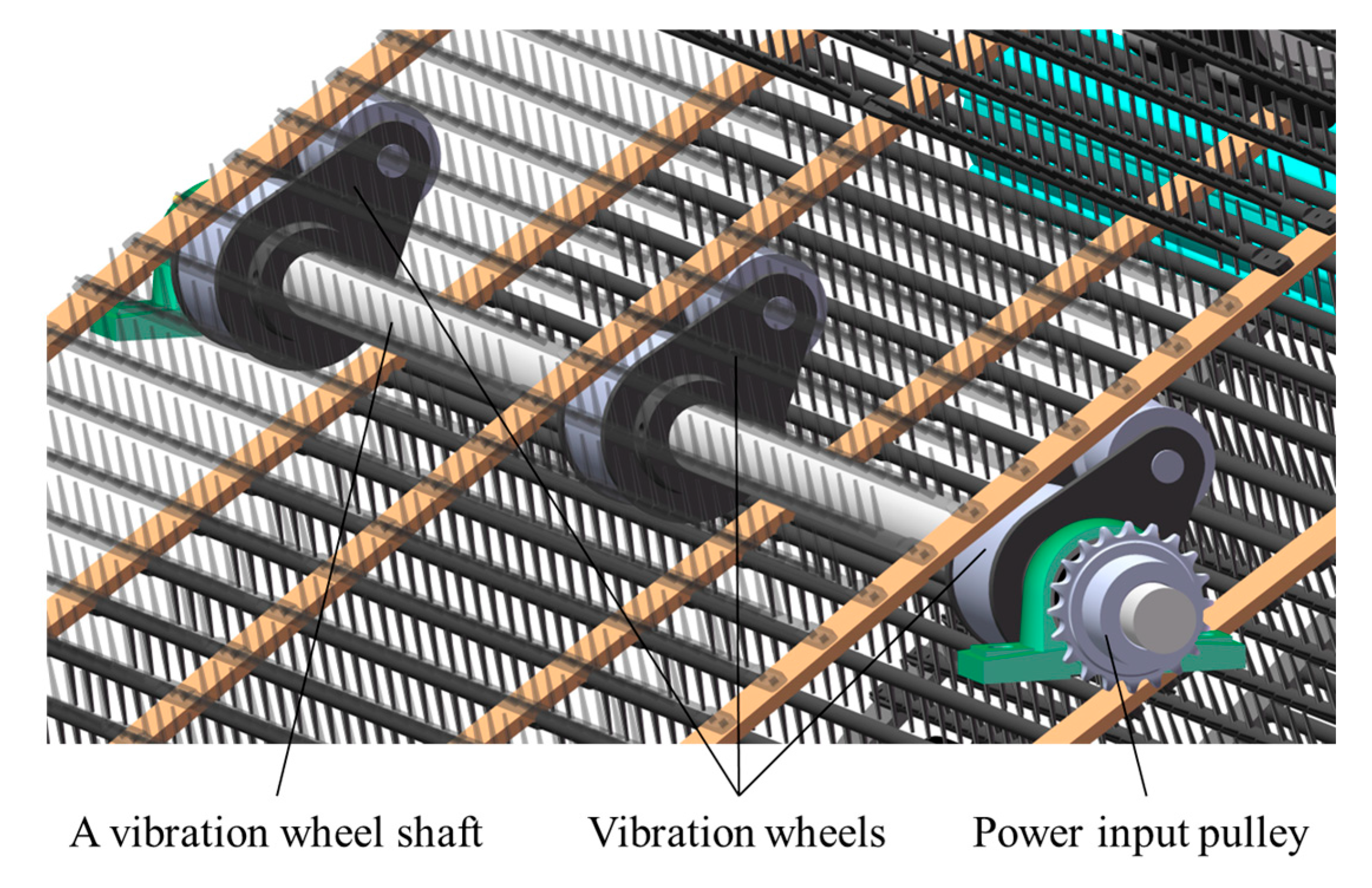
The process operates as follows: The primary vibratory chain conveyor transports the bulk soil–film mixture while simultaneously achieving preliminary separation. Intermeshing counter-rotating rollers then apply crushing compressive force to disintegrate soil clods adhering to or encapsulating film fragments. Finally, the secondary chain conveyor transfers the purified residual film to the collection bin. Compared to conventional technology, this structure adopts a coupled action of vibrating conveyor chains and a vibrating mechanism. This ensures that, while maintaining the integrity of the residual film, fine soil fragments are shaken off through the gaps in the conveyor chains and returned to the field, achieving primary film–soil separation. Based on this design, we conducted a mechanical analysis of film–soil composite conveyance stability on the primary chain. Using RecurDyn 2023 simulations for the vibration mechanism, we systematically identified key factors affecting preliminary separation efficiency. We then employed DEM–MBD coupled simulations to optimize parameters for maximum separation effectiveness. Subsequent field validation confirmed both the accuracy of the simulation model and the machine’s operational performance. This integrated approach establishes a critical theoretical foundation for achieving high-efficiency film–soil separation in subsurface residual film recovery systems.

2. Materials and Methods

2.1. Structure Composition and Working Principle

To address residual film pollution in cotton field subsurface soils, a novel subsurface residual film recovery machine was designed. The system comprises an excavation unit and film–soil vibrating conveying and separation device, which includes a primary conveyor chain, vibration mechanism, counter-rotating roller assembly, and secondary conveyor chain.
Due to the clod-digging excavation method, the material deposited on the primary conveyor chain consists of finely crushed soil, fragmented residual film, and film–soil composite clods. These composite clods form when residual film becomes tightly bound within compacted soil, effectively encapsulating film fragments. The primary conveyor chain transports the soil–film mixture rearward. A vibration mechanism mounted beneath the chain imparts mechanical vibration, dislodging a significant portion of finely crushed soil back into the field and achieving preliminary film–soil separation. The remaining composite clods and residual film are conveyed into the counter-rotating roller assembly. Here, the rollers apply compressive force, crushing the composite clods and completely releasing the encapsulated residual film from the soil, effecting further separation. The liberated residual film then falls onto the secondary conveyor chain. Finally, the secondary chain, assisted by a film-stripping roller, transports the film into the film collection bin (Figure 1).

2.2. Design of Key Components

2.2.1. Design of the Primary Conveyor Chain

As shown in Figure 2, the primary conveyor chain is a critical component of the film–soil vibrating conveying and separation device. It is responsible for transporting and separating residual plastic film, film–soil composite clods, and finely crushed soil. The chain assembly consists of a drive sprocket, a driven sprocket, and the conveyor chain itself.
Based on the analysis in Section 2.1, after the digging device excavates the topsoil and residual film, the material is conveyed to the primary conveyor chain. Consequently, the material on this chain consists primarily of three components: fine soil fragments, residual film, and film–soil composites. Here, the term “film-soil composite” refers to material where the residual film and soil are tightly bound together. The primary function of the conveyor chain is to achieve the initial conveying and separation of the fine soil fragments from the residual film and film–soil composites, while ensuring the stable transport of the film–soil composites. The conveyor chain inclination angle is one of its critical parameters. An excessive inclination angle can cause unstable conveying phenomena such as “jumping” or “rolling” of the film–soil composites. This instability can lead to the composites being ejected from the machine body, resulting in film loss. Conversely, an insufficient inclination angle leads to incomplete film–soil separation on the chain, causing the recovered film to have a high soil content. Therefore, to ensure the film–soil composites can be conveyed steadily on the chain, stability analysis of the composites on the conveyor chain is conducted.
To prevent film–soil composite clods from rolling off during operation, the chain incorporates flexible Y-shaped protrusion (Figure 2a). These pliable components offer excellent flexibility, high wear resistance, and significant resistance to rolling motion. This design feature ensures strong contact adhesion during the transport of soil and residual film, maintaining stability throughout the conveying process.
Figure 2b establishes a Cartesian coordinate system (xoy) for analyzing the conveyor chain transporting the film–soil composite mixture. We first analyze the equilibrium conditions of film–soil composite clods on the conveyor chain. For simplification, we approximate the film–soil composite mixture as circular particles.
Force analysis demonstrates that during upward conveyance, composite clods tend to roll downward along the chain. In this condition, the rolling resistance moment reaches its maximum value, opposing the impending rolling motion. Accordingly, we derive the following equilibrium equations for stable clod transportation.
G sin θ r M f = 0 F N G cos θ = 0
where Mf is rolling resistance couple (N·mm); θ is conveyor chain inclination angle (°); r is equivalent radius of the film–soil composite clod (mm) and FN is support force (N).
The supplementary equation for the critical state of impending rolling motion of the film–soil composite clod is given by
M f = δ F N
where δ is Rolling resistance coefficient (mm).
Solving Equations (1) and (2) simultaneously yields the conveyor inclination angle θ as
θ max = arc tan δ r
According to Equation (3), the condition to ensure stable conveyance of film–soil composite clods is
0 < θ θ max
According to reference [23], the rolling resistance coefficient δ between rubber and soil ranges from 10~15 mm. Preliminary measurements of film–soil composite clods yielded a maximum equivalent radius r of 46.34 mm. Substituting these values into Equation (4) determines the conveyor chain inclination angle θ to be 18~23.5°.

2.2.2. Analysis of the Vibration Mechanism

Installed beneath the conveyor chain, the vibration mechanism works synergistically with the primary conveyor chain to amplify vibrational motion (Figure 3). This action accelerates the shedding of finely crushed soil back into the field, achieving preliminary film–soil separation. The mechanism comprises three core components: A vibration wheel shaft, vibration wheels, and a power input pulley. During operation, the clockwise rotation of the vibration wheels induces periodic undulating vibrations in the conveyor chain. This enhanced agitation of film–soil composite clods during transport enables finely crushed soil to pass through chain gaps.
Based on theoretical analysis and references [24,25,26] concerning potato–soil vibration transportation studies, parameter ranges were established as follows: vibration wheel rotational speed: 150–220 r/min; installation distance: 500–950 mm; inclination angle: 18–24°. To identify dominant factors and quantify their influence on vibration characteristics, we performed RecurDyn 2023 simulations (Figure 4a). The conveyor chain was modeled as rigid links, while the vibration mechanism received an equivalent cam-follower system representation. The kinematic schematic (Figure 4b) incorporated corresponding joints. Simulation parameters (Table 1) were executed over 0.55 s. A specific point (Marker) on the vibrating rod was selected as the measurement point. Post-processing results appear in Figure 5, Figure 6 and Figure 7.
To quantitatively measure the impact of parameter variations on the motion state of the vibrating rod, the maximum resultant acceleration in the X and Y directions was output from the simulation results. The sensitivity of the acceleration to changes in each parameter was then calculated. Sensitivity is defined as the change in the vibrating rod’s acceleration per unit change in a parameter [27]. This metric is used to quantify the degree of influence that parameter variations have on the acceleration changes, as shown in Table 2.
As evident from Table 2, the sensitivity analysis indicates that changes in the vibrating wheel speed and mounting position exert the greatest influence on the motion state of the conveyor chain. Variations in the conveyor chain inclination angle exhibit a comparatively lesser effect. This demonstrates that inclination angles within the range of 18° to 24° have a relatively minor impact on the vibration characteristics.
Analysis in Section 2.2.1 demonstrated that an inclination angle between 18° and 23.5° ensures stable conveying of the film–soil composites on the chain. Therefore, an inclination angle of 23° was determined. This value guarantees stable conveying on the chain while avoiding adverse effects on the vibration characteristics of the vibrating mechanism. Consequently, the vibrating wheel mounting position and speed were selected as the key factors for quantitative experimental analysis.

2.3. DEM–MBD Coupled Simulation Experiment

2.3.1. Field Measurement

The field test was conducted on 7 October 2023, at a plastic–film-mulched cotton plantation base (41° N, 86° E) in Yuli County, Bayingolin Mongol Autonomous Prefecture, Xinjiang Uygur Autonomous Region. This site consists of farmland with continuous film-mulched cotton planting for 20 years, exhibiting significant accumulation of residual plastic film in the subsoil layer. The soil type is sandy loam, representing the primary soil type for cotton cultivation in Xinjiang.
As shown in Figure 8, soil sampling and residual film content measurement in the subsoil layer were performed using the five-point sampling method across the test area. Film–soil composites collected from the field were also analyzed, with results presented in the accompanying Table 3.

2.3.2. Development of a Film–Soil Composite Model for the Tillage Layer

Discrete element modeling of residual film–soil composites was developed using EDEM 2022 software. The research group conducted physical property tests and discrete element parameter calibration on residual film from this region in published papers. Through these studies, the intrinsic parameters of film, the contact parameters between various materials, and the bonding parameters have been successfully obtained [28].
Hertz–Mindlin with JKR is a cohesive contact model where surface energy represents interparticle attractive forces, suitable for simulating moist cohesive particles and agglomerated materials [28]. Given the relatively high moisture content in soil, interparticle adhesion occurs due to water molecule effects. The surface energy parameter in the JKR model effectively simulates this cohesive bonding between particles. Therefore, the present study adopts the Hertz–Mindlin with JKR contact model for soil simulations [21].
Regarding the film–soil composites, their substantial hardness prevents deformation on conveying chains. Consequently, a multi-sphere model was implemented for the film–soil composite particles. The modeling workflow commenced with 3D scanning of field-collected film–soil composites, generating surface meshes in .stl format. Following import into EDEM 2022 with a 3 mm smoothing tolerance, geometry-adapted particles were auto-generated using the multi-sphere filling algorithm. A 1700 mm (L) × 1400 mm (W) × 200 mm (H) tillage layer domain—containing stochastically distributed composites—was constructed. The established model is shown in Figure 9. Critical simulation parameters, including particle size distribution and JKR surface energy values, are cataloged in Table 4.

2.3.3. Multi-Flexible Body Dynamics Model Formulation

The DEM–MBD coupled simulation method was adopted to conduct the simulation experiment of film–soil conveying and separation for the primary conveyor chain [31]. The dynamic model of the film–soil separation conveyor was developed in RecurDyn 2023 by first creating its 3D geometry in SolidWorks 2022, exporting the assembly in .step format, and importing it into RecurDyn 2023 where structural steel material properties were assigned. Utilizing the Flexible Body module, tetrahedral finite element meshing was applied to the Y-shaped lugs, enabling rubber-like flexibility critical for conveying performance. Kinematic constraints, contact definitions between chain links, and rotational drives were implemented before exporting the conveyor boundaries as .wall files. Finally, the bidirectional co-simulation interface between RecurDyn 2023 and EDEM 2022 was activated to facilitate real-time data exchange and storage during coupled simulations [32,33]. The total simulation time was set to 5 s, with EDEM and RecurDyn timesteps configured at 1.8 × 10⁻⁶ s and 10−3 s, respectively. Subsequent analysis of the simulation results will characterize the dynamic behavior of the film and soil separation process, as visualized in the computational model (Figure 10).

2.3.4. Test Plan

Taking Primary Conveyor Chain Speed, vibration wheel rotational speed and installation distance as test factors, and soil content rate (Y1) and film leakage rate (Y2) as performance evaluation indicators, a single-factor test was conducted to examine the influence of each factor on the performance indicators, followed by further optimization of the factor value ranges [34]. A three-factor, five-level orthogonal test method was adopted to explore the optimal combination of structural parameters for the soil–film vibrating conveying and separation device. The factor levels are listed in Table 5. Each test group was repeated three times. With reference to “GB/T 25412-2021 Farm waste film-pick up machines” [35], the calculation formulas for soil content rate (Y1) and film leakage rate (Y2) are as follows:
Y 1 = 1 m 1 M × 100 %
Y 2 = m 2 m 1 + m 2 × 100 %
where Y1 is soil content rate, %; m1 is mass of recovered tillage-layer residual film, kg; M is total mass of recovered film–soil mixture, kg; Y2 is film leakage rate; m2 is mass of residual film fallen from the conveyor chain, kg.
During the simulation process, Grid Bin Groups were set up below and behind the conveyor chain within the Setup Selections module of EDEM’s Analyst function to monitor the mass of residual film m1, m2, and M [36,37]. Y1 and Y2 were then calculated according to Equations (5) and (6).

3. Results

3.1. Single-Factor Test Analysis

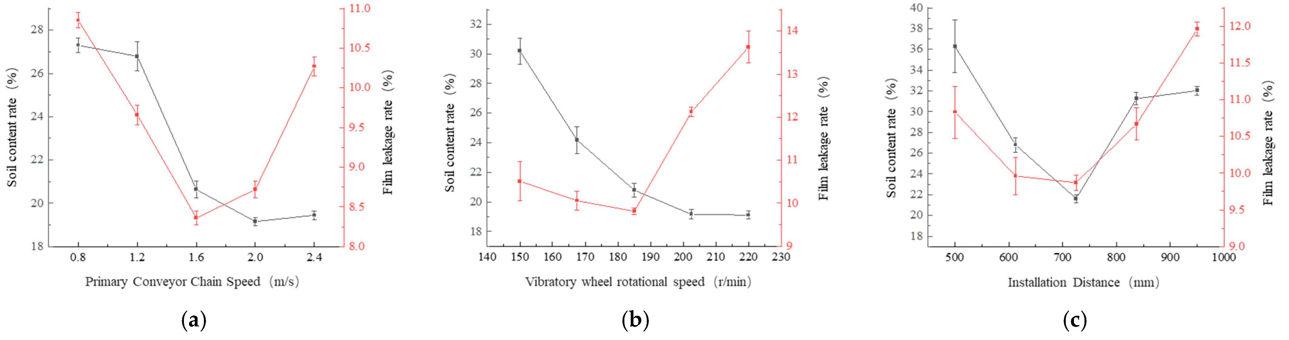
To further optimize the structural parameters, taking the primary conveyor Chain speed, vibration wheel rotational speed, and the installation distance as factors, and using the soil content rate Y1 and film leakage rate Y2 as the test indicators, a single-factor experiment was conducted. To minimize experimental variability, each test group was repeated for five replicates, with the averaged results serving as the experimental values.

3.1.1. Primary Conveyor Chain Speed

As shown in Figure 11a, the influence law of the speed of the primary conveyor chain on the soil content is that it first decreases and then increases as the speed of the primary conveyor chain increases. This is mainly because the primary conveyor chain can increase the disturbance of the film–soil mixture during the conveying process, so its influence on the soil content is relatively significant. The primary conveyor chain can transport a large amount of film–soil mixture as the speed increases, avoiding the accumulation of materials, thereby reducing the soil content. However, when the speed increases to a certain value, the film–soil composite can “jump” over the pinch roll mechanism and fall onto the second conveying chain, causing an increase in the soil content. The leakage of film increases with the increase in the speed of the primary conveyor chain. This is mainly because the increase in the speed of the primary conveyor chain increases the instability of the transportation of the film–soil mixture, causing some film–soil composites to “roll” and “jump”, resulting in an increase in the film leakage rate.

3.1.2. Vibration Wheel Rotational Speed

As shown in Figure 11b, the influence law of vibration wheel rotational speed on the soil content is that it decreases as the rotational speed of the vibration wheel increases. This is mainly because the increase in vibration wheel rotational speed enhances the vibration characteristics of the conveying chain. After the film soil mixture is subjected to the vibration of the conveying chain, the degree of film soil separation disturbance becomes greater. Therefore, it is easier to separate the film and soil. When it reaches a certain value, it can cause instability of the film–soil composite body and cause it to “jump” over the pair of rollers, resulting in the inability to crush the film soil composite body and an increase in the soil content. The influence law of vibration wheel rotational speed on the film leakage rate is that the film leakage rate first remains unchanged and then increases as the rotational speed of the vibration wheel increases. The reason is that the greater the rotational speed of the vibration wheel, the greater the impact force of the vibration collision on the conveying chain, resulting in more intense vibration “jumping” of the film–soil composite body in the later stage of the conveying process, causing the leakage phenomenon.

3.1.3. Installation Distance

As shown in Figure 11c, the influence law of installation distance on the soil content rate is that it decreases first and then remains stable as the installation distance increases. This is mainly because the smaller the installation distance of the vibration wheel, the less the vibration characteristics of the vibration wheel on the film–soil mixture are affected by the mass of the film–soil mixture, and the finer soil being transported will cause an increase in the soil content. As the installation distance increases, the vibration characteristics of the conveying chain also increase until the fine soil on the primary conveyor chain is completely “dusted off” onto the field. The influence law of installation distance on the leakage rate is that it increases first and then decreases as the installation distance increases. Combined with the explanation of the installation distance, if the installation distance of the vibration wheel is too small, it will cause the film–soil mixture thrown onto the conveying chain to be unstable, resulting in the film–soil mixture sliding off the conveying chain and falling outside the machine body. As the installation distance increases, when the film–soil mixture on the conveying chain presents a stable state, the vibration wheel shows regular vibration on the film–soil mixture at this time, and the film leakage rate decreases. If the installation distance is too large, the separated film–soil complex at the end of the conveying chain presents a “jumping” phenomenon, causing the film leakage rate to increase.

3.2. Test Results and Analysis of Variance

A three-factor, five-level orthogonal test comprising twenty experimental groups was executed according to the design. Each group was repeated three times, with the average values of soil content rate (Y1) and film leakage rate (Y2) recorded as experimental results. Analysis of variance (ANOVA) was performed using Design-Expert 13 software [38], yielding the test results summarized in Table 4 and ANOVA results in Table 6.
Analysis of Variance (ANOVA) results in Table 7 indicate statistically significant differences (p < 0.0001) for both the soil content rate and film leakage rate models. The lack-of-fit terms yielded p values of 0.7363 and 0.9592, demonstrating non-significance and confirming excellent model fitness. These validated models effectively describe experimental observations and demonstrate strong applicability for theoretical predictions of soil content rate and film leakage rate.
For the soil content rate performance metric, all three factors exhibited highly significant effects (p < 0.01), with the relative influence ranking as follows: primary conveyor chain speed > vibration wheel rotational speed > installation distance. Regarding the film leakage rate metric, all factors demonstrated significant impacts: both installation distance and vibration wheel rotational speed showed highly significant effects (p < 0.01), while primary conveyor chain speed had a significant effect (p < 0.05). The descending order of influence on missed film rate was installation distance > vibration wheel rotational speed > primary conveyor chain speed. After eliminating the insignificant factors, the regression equation obtained is
Y 1 = 17.65 + 0.88 X 1 0.45 X 2 0.37 X 3 0.6 X 1 X 2 + 0.47 X 2 X 3 + 0.49 X 1 2 + 1.02 X 2 2 + 1.28 X 3 2 Y 2 = 7.93 + 0.12 X 1 + 0.18 X 2 + 0.74 X 3 0.19 X 1 X 3 + 0.1 X 1 2 + 0.35 X 2 2 + 0.12 X 3 2

3.3. Parameter Optimization

The optimal parameter combination was determined by minimizing both soil content rate (Y1) and film leakage rate (Y2), while accounting for field operating conditions of the machinery: when the speed of the primary conveying chain was 1.61 m/s, the rotational speed of the vibration wheel was 186.2 r/min, and the installation distance was 688.2 mm, the soil inclusion rate Y1 and the film leakage rate Y2 reach their optimal values, which were 18.11% and 7.61%, respectively.

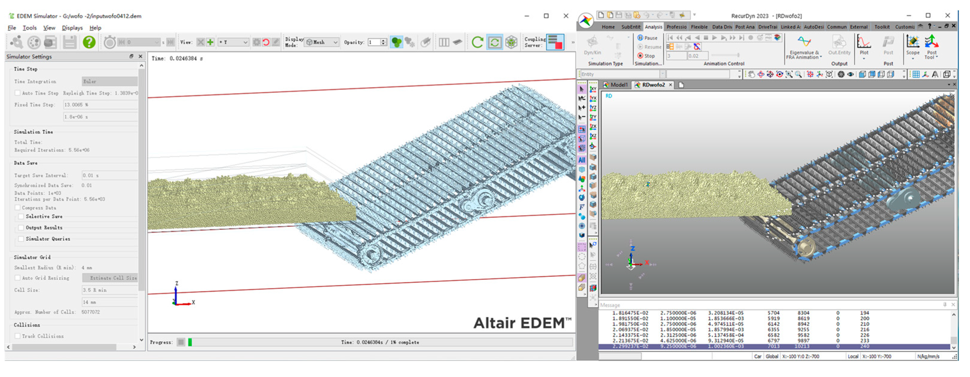
3.4. Analysis of Conveyance Vibration Process Based on Discrete Element Model

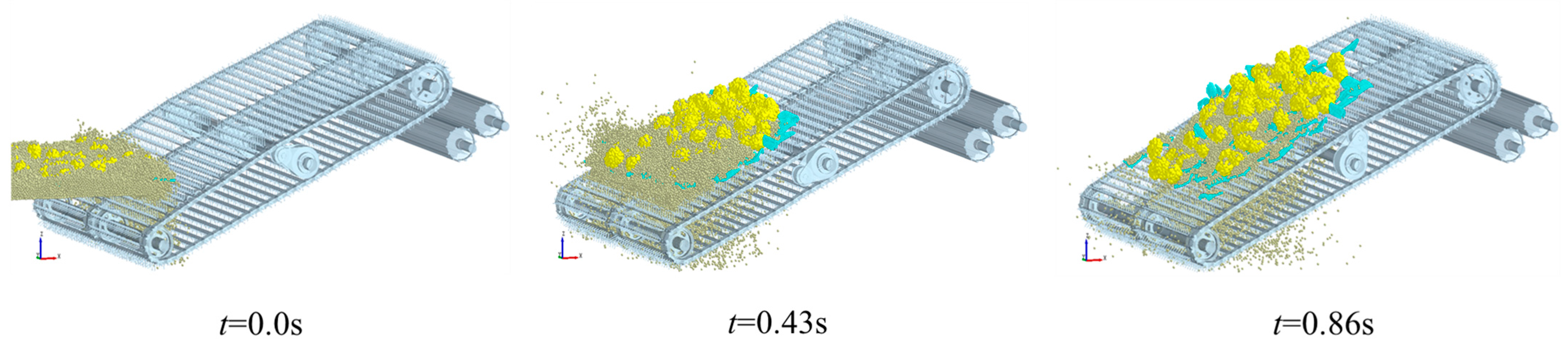
Figure 12 displays the numerical simulation results of the conveyance process [39,40,41], where fragmented soil particles are represented in dark yellow; film–soil composites are shown in yellow; and residual film are colored cyan.
Based on these results, the following conclusions are drawn. To facilitate description of this motion process, the film–soil vibrating conveying and separation device is divided into three functional zones: Conveying Zone, Vibration Zone, and Stable Transport Zone.
(1)
0–0.2 s: As the film–soil vibrating conveying and separation device advances, the primary conveyor chain first contacts the mixture of fragmented soil, film–soil composites, and residual film, supporting and conveying it upward. During this process, differential motion states emerge due to distinct physical properties of the three materials, enabling effective separation: film–soil composites exhibit “leaping” and “tumbling” behaviors; fragmented soil particles fall through gaps in the conveyor chain under combined effects of systemic vibration characteristics; minor vibrations from the flexible conveyor chain; residual film lies flat on the primary conveyor chain with minimal displacement.
(2)
0.2–0.43 s: As the mixture advances toward the vibration mechanism on the primary conveyor chain, enhanced segregation occurs among fragmented soil, film–soil composites, and residual film. At the vibration mechanism, soil particles exhibit increased fall-through from chain gap. Film–soil composites undergo vigorous leaping, tumbling, and return motions. Residual film shows low-amplitude vibration.
(3)
0.43–0.86 s: After complete discharge of fragmented soil, only film–soil composites and fragmented residual film remain. With increasing distance from the vibration mechanism, materials transition to stable conveyance states, which achieves primary separation efficiency.
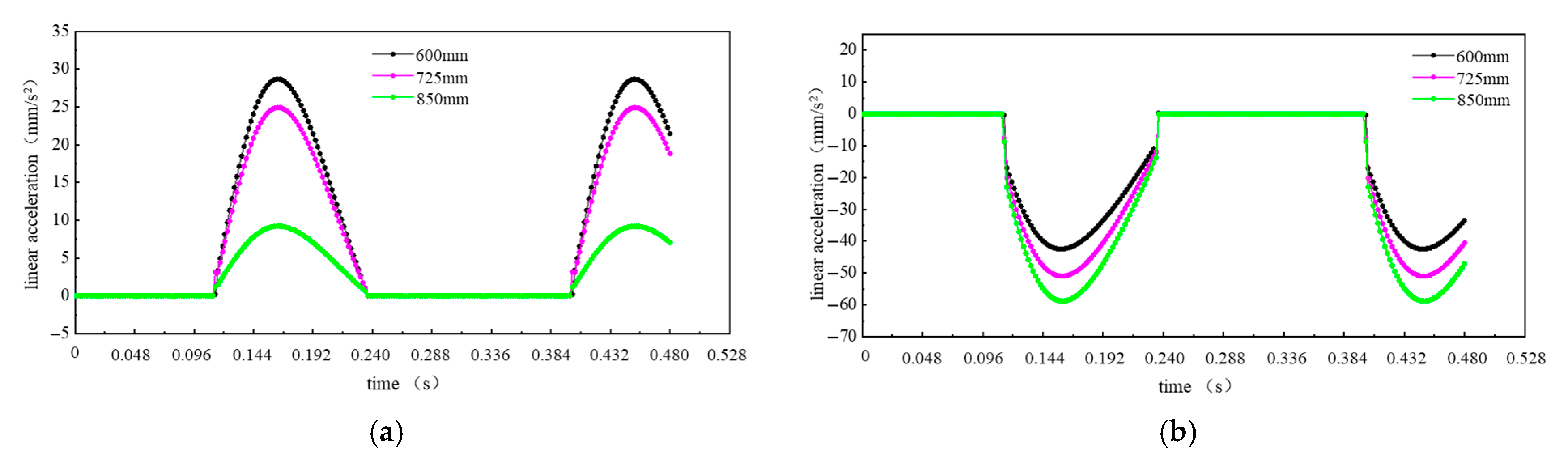
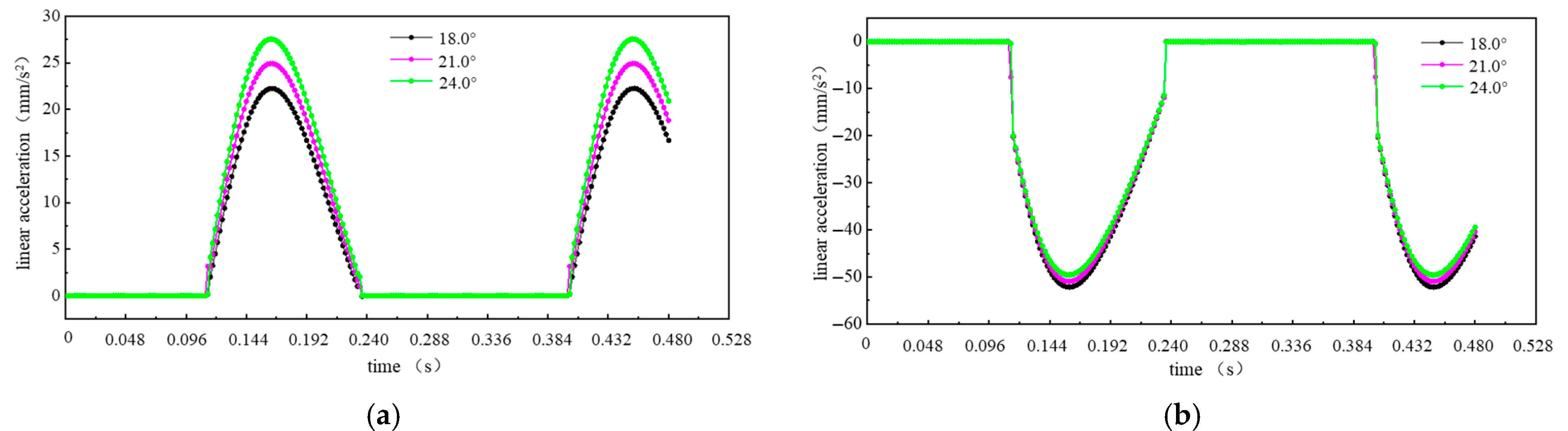
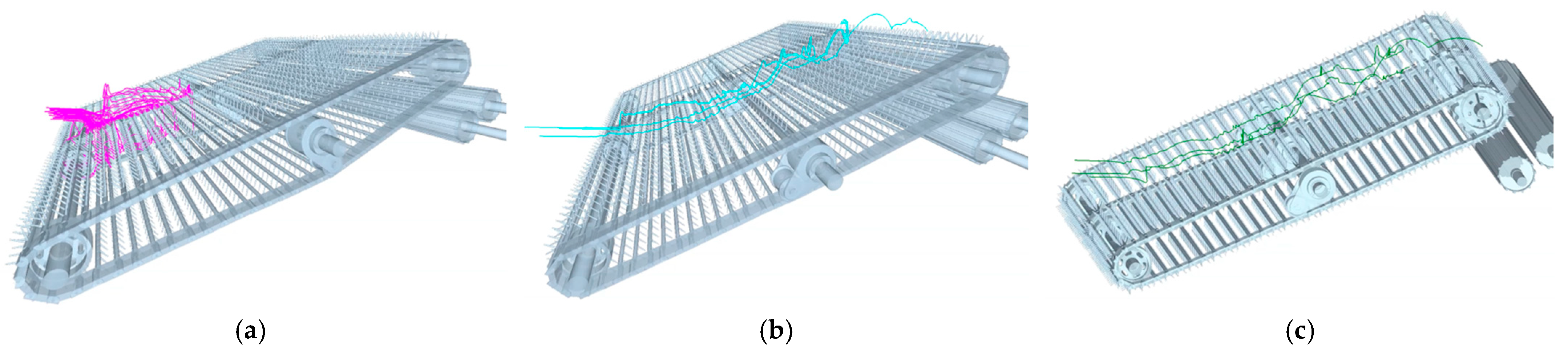
Figure 13 displays trajectories of finely crushed soil particles, film–soil composites, and residual film under identical conditions. Finely crushed soil particles fall through chain gaps under combined conveying and vibrational forces, with particle loss increasing along the conveyor length. Film–soil composites exhibit bouncing movement during rearward transport, showing greater bounce velocity amplitude near the vibration mechanism. As soil particles detach, residual film separates and lays flat on the conveyor chain. Motion simulation indicates residual film velocity is minimally affected by the vibration mechanism.

3.5. Field Validation Experiment Analysis

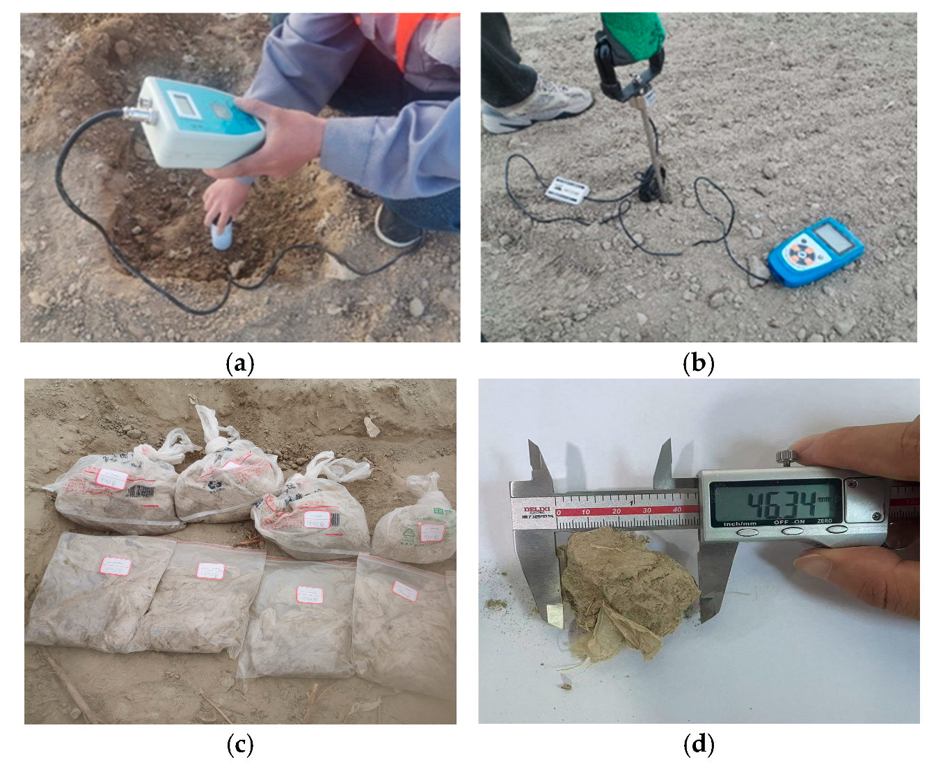
3.5.1. Experimental Methodology

To validate the reliability of theoretical simulation results, field tests were conducted in compliance with Standard “GB/T 25412-2021 Residual Film Recovery Machines” [42] and “NY/T 1277-2019 Operating Quality of Residual Film Recovery Machines” [
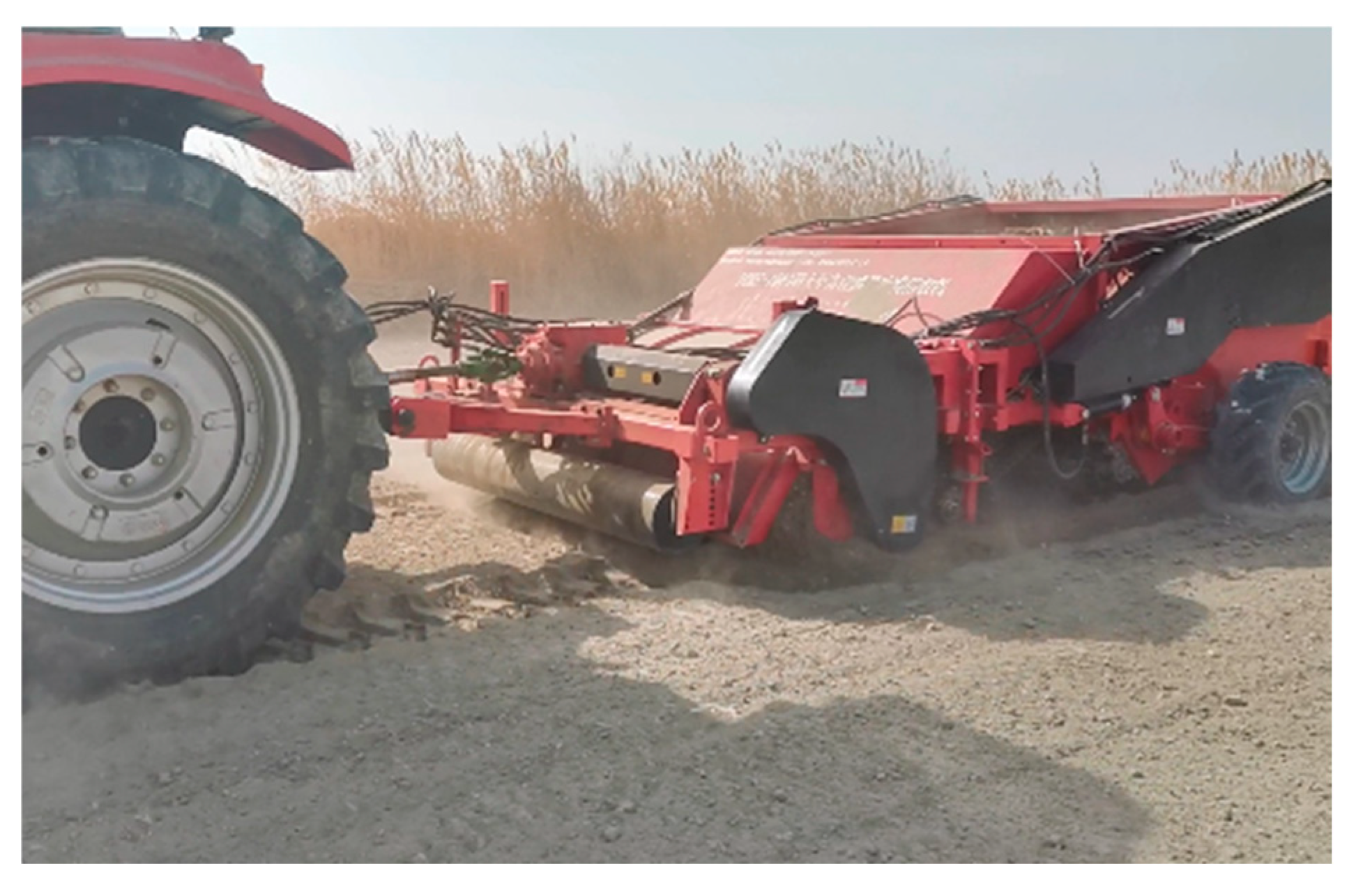
43]. Each test plot measured 10 m in length, with 2 m sections excluded at both acceleration and deceleration phases to ensure data accuracy. The central 6 m segment served as the data acquisition zone for calculating soil content rate and film miss rate. During the field experiment, the parameters of the film−soil vibrating conveying and separation device were set as follows: the speed of the primary conveyor chain was 1.61 m/s, the vibration wheel rotational speed was 186.2 r/min, and the installation distance was 688.2 mm. The test results are shown in Figure 14.

3.5.2. Analysis of Experimental Results

Field test outcomes are visualized in Figure 15, with quantitative measurements of soil content rate and film miss rate detailed in Table 8. Analysis shows that, in the film soil effects of the five field experiments, the average values of soil content rate and film leakage rate were 18.72% and 8.03%, respectively, which differed from the predicted results of the regression model by 3.43% and 5.51%, respectively. The field traversability performance and film–soil separation efficiency met all requirements specified in Chinese National Standard “GB/T 25412-2021 Residual Film Recovery Machines” [42].

4. Discussion

This study primarily investigated the conveying and vibratory separation dynamics of film–soil composites during tillage-layer residual film recovery. In the contact force analysis between conveyor chains and composites, only theoretical mechanical states were considered, while material fatigue properties under actual operating conditions were not incorporated. For computational simulations, a coupled EDEM–RecurDyn approach analyzed the motion of transported materials (residual film, soil, and film–soil composite), where suboptimal discrete element parameter selection could induce simulation errors. Field validation was conducted exclusively under single-soil conditions to assess separation performance. Future research should expand to multi-regional field trials across diverse pedological conditions in Xinjiang to optimize machine design and enhance field adaptability.

5. Conclusions

(1)
To address residual film pollution in Xinjiang’s farmland tillage layer, a tillage-layer residual film recovery machine was developed, achieving high-efficiency film–soil separation and recovery. The machine’s overall structure and working principles are described.
(2)
The design of the membrane–soil vibration separation unit was prioritized. By establishing a mechanical model for conveying the film–soil composite, the conveying chain inclination angle range was determined to be 18–23.5°. Using RecurDyn 2023, the influence levels of the vibrating wheel speed, vibrating wheel installation distance, and conveying chain inclination angle on the vibration characteristics were investigated. Ultimately, the conveying inclination angle was set at 23°.
(3)
A DEM–MBD model integrating the vibrating conveying unit, residual plastic film, and soil was developed. Single-factor experiments and a three-factor, five-level orthogonal rotational central composite design experiment were conducted. The optimal parameter combination for the unit’s working performance was determined as follows: primary conveying chain speed of 1.61 m/s, vibrating wheel speed of 186.2 rpm, installation distance of 688.2 mm, resulting in a soil content rate of 18.11% and a film leakage rate of 7.61%.
(4)
Field verification tests were conducted on the optimized parameter combination, with relative errors of 3.43% and 5.51%, respectively. The test results proved that the film–soil vibrating conveying and separation device could better achieve the film–soil separation function, providing theoretical basis and equipment support for solving the problem of residual film pollution in the plow layer in Xinjiang.

Author Contributions

Conceptualization, S.S. and J.Z.; methodology, S.S., J.Z. and Y.J.; software, S.S. and X.Z.; validation, S.S., Y.W., X.Z. and X.L.; formal analysis, S.S., J.Z. and X.Z.; investigation, J.Z., S.S., Y.J., H.Z. (Hu Zhang) and H.Z. (Haichun Zhang); data curation, S.S., X.Z., J.Z. and H.Z. (Hu Zhang); writing—original draft preparation, S.S. and J.Z.; writing—review and editing, S.S., J.Z. and Y.W.; visualization, S.S., Y.W. and X.L.; supervision, J.Z. and H.Z. (Hu Zhang); funding acquisition, J.Z. All authors have read and agreed to the published version of the manuscript.

Funding

This research was funded by the Science and Technology Innovation Leading Talent Project, grant number 2024TSYCLJ0014, the Xinjiang Uygur Autonomous Region Graduate Research Innovation Project, grant number XJ2024G103, the Xinjiang Uygur Autonomous Region “Unveiling and Leading” Project “High-Quality and High-Efficiency Mechanized Recovery Technology R&D and Equipment Application for Farmland Plastic Film Residue”, and the Xinjiang Uygur Autonomous Region “Unveiling and Leading” Project, grant number XJJBGS-MG202403. These funding sources supported the costs of experimental materials, study design, data collection, analysis and interpretation, manuscript preparation, and the decision to submit the article for publication.

Institutional Review Board Statement

Not applicable.

Informed Consent Statement

This work constitutes agricultural machinery research involving theoretical analysis and computational simulations of mechanical structures. It does not include human participants, animal experimentation, or confidential personal data.

Data Availability Statement

All data are presented in this article in the form of figures and tables. There is no Plagiarism, Data Fabrication, or Image Manipulation.

Acknowledgments

The authors thank the editor and anonymous reviewers for providing helpful suggestions for improving the quality of this manuscript.

Conflicts of Interest

The authors declare no conflicts of interest. The decision to submit this manuscript for publication was made collectively by all authors. We confirm that no conflicts of interest exist with any supporting sources.

References

  1. Wang, D.W.; Wang, Z.H.; Ding, H.W.; Zhou, B.; Zhang, J.Z.; Li, W.H. Effects of biodegradable mulching films on soil hydrothermal conditions and yield of drip-irrigated cotton (Gossypium hirsutum L.). Int. J. Agric. Biol. Eng. 2022, 15, 153–164. [Google Scholar] [CrossRef]
  2. Zhao, P.; Lyu, H.; Wang, L.; Zhang, H.; Li, Z.; Li, K.; Xing, C.; Guo Yao, B. Optimization Design of Straw-Crushing Residual Film Recycling Machine Frame Based on Sensitivity and Grey Correlation Degree. Agriculture 2024, 14, 764. [Google Scholar] [CrossRef]
  3. Wei, L.; Liu, X.; Sun, W.; Zhao, W.; Li, H.; Zhang, H.; Li, H.; Liang, J.; Li, Y.; Zhou, Y.; et al. Design and Testing of an Integrated Corn Stubble Residual Film-Recycling Machine. Agriculture 2024, 14, 1809. [Google Scholar] [CrossRef]
  4. Song, Z.; Lian, X.; Ran, J.; Zheng, X.; Wang, X.; Lian, X. Effect of Cotton Stalk Biochar Content on the Properties of Cotton Stalk and Residual Film Composites. Agriculture 2025, 15, 1243. [Google Scholar] [CrossRef]
  5. Duan, X.; Luo, T.; Ding, Y.; Han, X.; Li, H.; Wang, H. The Impact of Vineyard Mulch on Soil Quality and Biological Diversity. Agriculture 2025, 15, 927. [Google Scholar] [CrossRef]
  6. Song, Z.; Zhao, L.; Bi, J.; Tang, Q.; Wang, G.; Li, Y. Classification of Degradable Mulch Films and Their Promotional Effects and Limitations on Agricultural Production. Agriculture 2024, 14, 1235. [Google Scholar] [CrossRef]
  7. Fang, W.; Wang, X.; Zhu, C.; Han, D.; Zang, N.; Chen, X. Analysis of Film Unloading Mechanism and Parameter Optimization of Air Suction-Type Cotton Plough Residual Film Recovery Machine Based on CFD—DEM Coupling. Agriculture 2024, 14, 1021. [Google Scholar] [CrossRef]
  8. Shen, S.L.; Zhang, J.X.; Jiang, Y.X.; Wang, Y.C.; Liu, X.F.; Li, J.M.; Dong, W.H. Tensile Properties of Residual Film in Tillage Layer Based on Discrete Element Method. Trans. Chin. Soc. Agric. Mach. 2024, 55, 132–141. [Google Scholar] [CrossRef]
  9. Zhang, X.; Guo, L.; Yan, J.; Shi, Z.; Kang, M.; Yao, J. Simulation Analysis and Parameter Optimization of Residual Film Pickup Process Based on Finite Element Method. Agriculture 2024, 14, 524. [Google Scholar] [CrossRef]
  10. Wang, J.; Zhao, W.; Liu, X.; Dai, F.; Shi, R.; Zhang, K.; Wang, X.; Zhang, W.; Liang, J. The Design and Testing of a Combined Operation Machine for Corn Straw Crushing and Residual Film Recycling. Agriculture 2025, 15, 916. [Google Scholar] [CrossRef]
  11. Jiang, D.; Chen, X.; Yan, L.; Zhang, J.; Wu, T.; Fu, X. Design and Testing of Friction-Type Nail-Tooth-Chain-Plate Residual-Film-Picking System. Agriculture 2024, 14, 512. [Google Scholar] [CrossRef]
  12. Jiang, S.; Chen, B.; Jiang, H.; Guo, P.; Wang, X.; Hu, C.; Guo, W. Simulation and Evaluation of the Performance of Pneumatic Residual Film Recycler Comb Teeth. Agriculture 2025, 15, 811. [Google Scholar] [CrossRef]
  13. Zhang, Z.Y.; Chen, X.G.; Wang, X.F.; Xue, S.K.; Li, J.B. Design and test of the arc-shaped nail-tooth roller residual film recovery machine from the sowing layer. Int. J. Agric. Biol. Eng. 2024, 17, 90–98. [Google Scholar] [CrossRef]
  14. Shi, Z.L.; Zhang, X.J.; Liu, X.P.; Guo, L.; Zhang, C.S.; Liu, L. Design and Test of Roll-type Tillage Layer Residual Film Recovery Machine. Trans. Chin. Soc. Agric. Mach. 2024, 55, 128–137. [Google Scholar] [CrossRef]
  15. Zhang, X.J.; Liu, J.Q.; Shi, Z.L.; Jin, W.; Yan, J.S.; Yu, M.J. Design and parameter optimization of reverse membrane and soil separation device for residual film recovery machine. Trans. Chin. Soc. Agric. Eng. 2019, 35, 46–55. [Google Scholar] [CrossRef]
  16. Guo, W.S.; He, X.W.; Wang, L.; Zhao, P.F.; Hu, C.; Hou, S.L.; Wang, X.F. Development of a comb tooth loosening and pneumatic stripping plough layer residual film recovery machine. Trans. Chin. Soc. Agric. Eng. 2020, 36, 1–10. [Google Scholar] [CrossRef]
  17. Luo, K.; Yuan, P.P.; Jin, W.; Yan, J.S.; Bai, S.H.; Zhang, C.S.; Zhang, X.J. Design of chain-sieve type residual film recovery machine in plough layer and optimization of its working parameters. Trans. Chin. Soc. Agric. Eng. 2018, 34, 19–27. [Google Scholar] [CrossRef]
  18. Zhang, Z.H. Design and Research of the Air Separation Type Reclaimer for the Residual Film of Plough Layer; Shanxi Agricultural University: Jinzhong, China, 2020. [Google Scholar]
  19. Yao, J.T.; Zhang, X.J.; Shi, Z.L.; Liu, X.P.; Kang, M.C.; Guo, L. Research status and development trend of tillage layer residual film recycling machine. J. Chin. Agri. Mech. 2024, 45, 290–295. [Google Scholar] [CrossRef]
  20. Zhang, S.L.; Zhao, H.B.; Wang, X.Z.; Dong, J.X.; Zhao, P.F.; Yang, F.F.; Chen, X.H.; Liu, F.; Huang, Y.X. Discrete element modeling and shear properties of the maize stubble-soil complex. Comput. Electron. Agric. 2023, 204, 107519. [Google Scholar] [CrossRef]
  21. Zeng, Y.; Jiang, X.H.; Wu, M.L.; Zhao, Z.H.; Tang, L.W.; Li, P.C. Development of the layered cut and throw ditching blade groups for oil tea forest based on DEM-MBD. Trans. Chin. Soc. Agric. Eng. 2024, 40, 30–42. [Google Scholar] [CrossRef]
  22. Yang, Q.Z.; Yang, X.Y.; He, M.S.; Zhang, R.Y.; Wen, T.N.; Shi, A.P. Design and experiment of the rotary throwing knife of wine grape cleaning machine. Trans. Chin. Soc. Agric. Eng. 2022, 38, 44–51. [Google Scholar] [CrossRef]
  23. Zhang, Q.L.; Cui, X.J. Dual Roller Tire Rolling Resistance Based on Linear Regression Orthogonal Experiment. Tract. Farm. Transporter. 2011, 38, 21–23. [Google Scholar]
  24. Lu, J.Q.; Yang, X.H.; Lu, Y.N.; Li, Z.H.; Li, J.C.; Du, C.L. Analysis and Experiment of Potato Damage in Process of Lifting and Separating Potato Excavator. Trans. Chin. Soc. Agric. Eng. 2023, 51, 103–113. [Google Scholar] [CrossRef]
  25. Lü, J.Q.; Tian, Z.G.; Wu, J.; Yang, Y.; Shang, Q.Q.; Wang, Y.B.; Liu, Z.X. Design and experiment on 4U1Z vibrating potato digger. Trans. Chin. Soc. Agric. Eng. 2015, 31, 39–47. [Google Scholar] [CrossRef]
  26. Wei, Z.C.; Li, H.W.; Sun, C.Z.; Li, X.Q.; Liu, W.Z.; Su, G.L.; Wang, F.M. Improvement of potato harvester with two segment of vibration and wave separation. Trans. Chin. Soc. Agric. Eng. 2018, 34, 42–52. [Google Scholar] [CrossRef]
  27. Wang, Z.H. Virtual Design of Cleaning Plant of Cole Harvester Based on ADAMS And Test Research; Jiangsu University: Zhenjiang, China, 2003. [Google Scholar]
  28. Che, H.L.; Zhou, H.; Zhang, Y.P.; Li, Z.Z.; Wang, X.; Li, J.Y.; Chen, J.L.; Zhou, H. Parameter optimization and numerical analysis of the double disc digging shovel for corn root-soil complex. Comput. Electron. Agric. 2025, 235, 110386. [Google Scholar] [CrossRef]
  29. Liu, X.; Shi, R.; Zhao, W.; Sun, W.; Li, P.; Li, H.; Zhang, H.; Wang, J.; Wang, G.; Dai, F. Study on the Characteristics of Residual Film–Soil–Root Stubble Complex in Maize Stubble Fields of the Hexi Corridor and Establishment of a Discrete Element Model. Agriculture 2024, 14, 1542. [Google Scholar] [CrossRef]
  30. Zhong, J.Q.; Tao, L.M.; Li, S.P.; Che, R.F.; Li, K.H.; He, Y.L. Design and experiments of a seed clearing, reseeding and elevating type seed metering device for sugarcane. Trans. Chin. Soc. Agric. Eng. 2023, 39, 43–54. [Google Scholar] [CrossRef]
  31. Hou, S.; Wang, S.; Ji, Z.; Zhu, X. Design and Test of the Clearing and Covering of a Minimum-Tillage Planter for Corn Stubble. Agriculture 2022, 12, 1209. [Google Scholar] [CrossRef]
  32. Liu, W.R.; Zhang, G.Z.; Liu, H.P.; Zhou, Y.; Wang, H.C.; Pei, L.; Li, Z.H. Design and experiment of the centrifugal rotary root-soil separation device for a multiple taro harvester. Trans. Chin. Soc. Agric. Eng. 2024, 40, 14–26. [Google Scholar] [CrossRef]
  33. Chen, G.B.; Wang, Q.J.; Lia, H.W.; Jin, H.; Wang, H.; Zhang, X.Y.; He, D. Experimental research on vertical straw cleaning and soil tillage device based on Soil-Straw composite model. Comput. Electron. Agric. 2024, 216, 108510. [Google Scholar] [CrossRef]
  34. Zhang, G.Z.; Zhang, Q.H.; Liu, W.R.; Li, Z.H.; Zhou, Y.; Liu, H.P. Spring roller device for soil-corm separation for a water chestnut harvester. Trans. Chin. Soc. Agric. Eng. 2024, 40, 164–175. [Google Scholar] [CrossRef]
  35. GB/T 25412-2021; Residual Plastic Film Recovery Machine. National Technical Committee on Standardization of Agricultural Machinery of China: Beijing, China, 2021.
  36. Sun, X.B.; Niu, L.H.; Cai, M.C.; Liu, Z.; Wang, Z.H.; Wang, J.W. Particle motion analysis and performance investigation of a fertilizer discharge device with helical staggered groove wheel. Comput. Electron. Agric. 2023, 213, 108241. [Google Scholar] [CrossRef]
  37. He, S.Y.; Qian, C.; Jiang, Y.C.; Qin, W.; Huang, Z.H.; Huang, D.M.; Wang, Z.M.; Zang, Y. Design and optimization of the seed feeding device with DEM-CFD coupling approach for rice and wheat. Comput. Electron. Agric. 2024, 219, 108814. [Google Scholar] [CrossRef]
  38. Gu, F.W.; Zhao, Y.Q.; Wu, F.; Hu, Z.C.; Shi, L.L. Simulation analysis and experimental validation of conveying device in uniform rrushed straw throwing and seed-sowing Machines using CFD-DEM coupled approach. Comput. Electron. Agric. 2022, 193, 106720. [Google Scholar] [CrossRef]
  39. Xu, L.Z.; Li, Y.; Chai, X.Y.; Wang, G.M.; Liang, Z.W.; Li, Y.M.; Li, B.J. Numerical simulation of gas-solid two-phase flow to predict the cleaning performance of rice combine harvesters. Biosyst. Eng. 2020, 190, 11–24. [Google Scholar] [CrossRef]
  40. Lu, J.Q.; Sun, H.; Dui, H.; Peng, M.M.; Yu, J.Y. Design and Experiment on Conveyor Separation Device of Potato Digger under Heavy Soil Condition. Trans. Chin. Soc. Agric. Eng. 2017, 48, 146–155. [Google Scholar] [CrossRef]
  41. Zhang, L.; Wang, X.; Chen, J.; Wang, H.; Cao, Y. Analysis and Optimization of Low-Resistance Animal Bionic Subsoiling Shovel Based on EDEM. Agriculture 2024, 14, 2046. [Google Scholar] [CrossRef]
  42. GB/T 25412-2021; Farm Waste Film-Pick up Machines. Standards Press of China: Beijing, China, 2021.
  43. NY/T 1277-2019; The Operating Quality of Retrieving Machines for Film Residue. Ministry of Agriculture and Rural Affairs of the People’s Republic of China: Beijing, China, 2019.
Figure 1. Configuration and working principle of the subsurface residual film recovery machine.
Agriculture 15 01501 g001
Figure 2. Conveyor system and force analysis. (a) Film–soil composite conveyor system; (b) force analysis of film–soil composite transport.
Agriculture 15 01501 g002
Figure 3. Vibration mechanism.
Agriculture 15 01501 g003
Figure 4. Schematic diagram of vibration mechanism. (a) Simulation model; (b) equivalent kinematic schematic of vibration mechanism.
Agriculture 15 01501 g004
Figure 5. Effect of vibration wheel rotational speed on acceleration of rigid link. (a) In x-direction; (b) In y-direction.
Agriculture 15 01501 g005
Figure 6. Effect of installation distance on acceleration of rigid links. (a) In x-direction; (b) in y-direction.
Agriculture 15 01501 g006
Figure 7. Effect of conveyor chain inclination angle on acceleration of rigid links. (a) In x-direction; (b) In y-direction.
Agriculture 15 01501 g007
Figure 8. Field measurement. (a) Soil moisture content determination; (b) soil penetration resistance measurement; (c) measurement of residue film content in the plow layer; (d) measurement of film–soil composite.
Agriculture 15 01501 g008
Figure 9. Discrete element model of film–soil mixture. (a) Simulation model; (b) film–soil composite model; (c) soil model; (d) film model; (e) the distribution of residual film in the soil.
Agriculture 15 01501 g009
Figure 10. Film–soil transport simulation.
Agriculture 15 01501 g010
Figure 11. Single-factor test results. (a) Influence of primary conveyor chain speed on performance metrics; (b) influence of vibration wheel rotational speed on performance metrics; (c) influence of installation distance on performance metrics.
Agriculture 15 01501 g011
Figure 12. Simulation analysis of film–soil conveying and separation process.
Agriculture 15 01501 g012
Figure 13. Trajectories during film–soil conveyance process. (a) Finely crushed soil particle trajectory; (b) film–soil composite trajectory; (c) residual film trajectory.
Agriculture 15 01501 g013
Figure 14. Field validation test.
Agriculture 15 01501 g014
Figure 15. Conveyor system and force analysis. (a) Conveying state of residual film; (b) recovered residual film; (c) operational effectiveness.
Agriculture 15 01501 g015
Table 1. Simulation test parameters of vibration mechanism.
LevelFactors
Vibration Wheel Rotational Speed/r·min−1Installation Distance/mmConveyor Chain Inclination Angle/(°)
115050018.0
218572521.0
322095024.0
Table 2. Sensitivity analysis of various factors on vibrating rod acceleration.
TypeLevelax max (mm·s−2)ay max (mm·s−2)Sensitivity
Vibration wheel rotational speed (r·min−1)15015.9432.560.6521
18524.9651.32
22035.6273.75
Installation distance (mm)50028.6841.390.2227
72524.9651.32
9509.1659.68
Conveyor chain inclination angle (°)18.022.4649.950.076
21.024.9651.32
24.027.5852.53
Table 3. Field measurement results.
ParameterValue
Soil moisture content (%) 13.9
Soil penetration resistance (kpa) 5394
Mass content of residual film (g·m−2)0~100 mm12.39
100~200 mm11.63
Equivalent diameter of film–soil composite aggregate (mm) 46.34
Table 4. Material physical and contact mechanical properties parameters.
TypeParameterValueSource
Intrinsic parametersRadius of soil particles (mm)4[28]
Soil Poisson’s ratio0.32[28]
Soil density/(kg·m−3)2.15 × 103[28]
Soil shear modulus/Pa4.5 × 106[28]
Radius of residual film particles (mm)0.8[8,29]
Residual film Poisson’s ratio0.5[8,29]
Residual film density/(kg·m−3)860[8,29]
Residual film shear modulus/Pa8.3 × 108[8,29]
Rubber Poisson’s ratio0.25[8,30]
Rubber shear modulus/Pa7.90 × 1010[8,30]
Rubber density/(kg·m−3)7.86 × 103[8,30]
Bonding parameters of residual filmNormal stiffness per unit area/(N·m−3)5 × 108[8]
Shear stiffness per unit area/(N·m−3)5 × 109[8]
Critical normal stress/Pa3 × 106[8]
Critical Shear stress/Pa3 × 106[8]
Bonding radius (mm)1[8]
Contact parameters of soilSoil–soil coefficient of restitution0.21[28]
Soil–soil coefficient of rolling friction0.2[28]
Soil–soil coefficient of static friction0.32~1.04[28]
Soil–film coefficient of restitution0.31[29]
Soil–film coefficient of rolling friction0.28[29]
Soil–film coefficient of static friction0.65[29]
Soil–rubber coefficient of restitution0.5~1.2[30]
Soil–rubber coefficient of rolling friction0.2[30]
Soil–rubber coefficient of static friction0.9[30]
JKR parameterSurface energy of soil (J·m−2)12[28]
Table 5. Factors and codes of experiments.
Coded ValuePrimary Conveyor Chain Speed X1/(m·s−1)Vibration Wheel Rotational Speed X2/(r·min−1)Installation Distance X3/(mm)
−1.6821.20167.5612.5
−11.36174.6658.1
01.60185.0725.0
11.83195.4791.8
1.6822.00203.0837.5
Table 6. Experiment scheme and results.
Test No.X1/(m·s−1)X2/(r·min−1)X3/(mm)Y1/%Y2/%
1−1−1−120.547.46
21−1−123.357.88
3−11−120.047.49
411−119.818.33
5−1−1118.679.12
61−1121.728.69
7−11119.419.45
811120.679.62
9−1.6820017.328.03
101.6820020.398.47
110−1.682020.938.72
1201.682019.869.16
1300−1.68221.666.98
14001.68220.589.62
1500018.238.01
1600017.437.68
1700017.548.21
1800016.938.16
1900018.077.69
2000017.727.84
Table 7. Variance analysis.
SourceDegree of FreedomY1Y2
Sum of Mean SquaresF Valuep ValueSum of Mean SquaresF Valuep Value
Model956.6637.04<0.0001 **10.6837.88<0.0001 **
X1110.6462.60<0.0001 **0.22177.080.0239 *
X212.7716.290.0024 **0.450314.380.0035 **
X311.8911.150.0075 **7.56241.27<0.0001 **
X1X212.9217.160.0020 **0.13004.150.0689
X1X310.37412.200.16870.28889.220.0125 *
X2X311.7410.230.0095 **0.07602.430.1503
X1213.3019.400.0013 **0.16525.270.0445 *
X22115.0788.70<0.0001 **1.7856.68<0.0001 **
X32123.58138.74<0.0001 **0.22437.160.0233 *
Residual101.70 0.3133
Lack of Fit50.60280.54980.73630.04740.17820.9592
Pure Error51.10 0.2659
Total1958.36 10.99
Note: ** indicates that the impact is extremely significant, p < 0.01; * indicates that the impact is significant, p < 0.05.
Table 8. Variance analysis.
Coded ValueSoil Content Rate (%)Film Leakage Rate (%)
119.178.10
218.037.99
319.318.12
418.618.01
518.537.91
Mean value18.738.03
Theoretical Value18.117.61
Mean relative error3.435.51
Disclaimer/Publisher’s Note: The statements, opinions and data contained in all publications are solely those of the individual author(s) and contributor(s) and not of MDPI and/or the editor(s). MDPI and/or the editor(s) disclaim responsibility for any injury to people or property resulting from any ideas, methods, instructions or products referred to in the content.

