Article

Design and Field Experiment of Synchronous Hole Fertilization Device for Maize Sowing

by
Feng Pan
1,2,
Jincheng Chen
1,2,
Baiwei Wang
1,2,
Ziheng Fang
1,2,3,
Jinxin Liang
1,2,3,
Kangkang He
1,2,3 and
Chao Ji
1,2,3,*
1
Institute of Mechanical Equipment, Xinjiang Academy of Agricultural and Reclamation Science, Shihezi 832000, China
2
Key Laboratory of Northwest Agricultural Equipment, Ministry of Agriculture and Rural Affairs, Shihezi 832003, China
3
College of Mechanical and Electrical Engineering, Shihezi University, Shihezi 832003, China
*
Author to whom correspondence should be addressed.
Agriculture 2025, 15(13), 1400; https://doi.org/10.3390/agriculture15131400
Submission received: 4 June 2025 / Revised: 25 June 2025 / Accepted: 27 June 2025 / Published: 29 June 2025
(This article belongs to the Section Agricultural Technology)

Abstract

The disadvantages of traditional strip fertilization technology for corn planting in China include low fertilizer utilization rates, unstable operation quality, and environmental pollution. Therefore, in this study, a synchronous hole fertilization device for corn planting based on real-time intelligent control is designed, aiming to reduce fertilizer application and increase efficiency through the precise alignment technology of the seed and fertilizer. This device integrates an electric drive precision seeding unit, a slot wheel hole fertilization unit, and a multi-sensor coordinated closed-loop control system. An STM32 single-chip micro-computer is used to dynamically analyze the seed–fertilizer timing signal, and a double closed-loop control strategy (the position loop priority is higher than the speed loop) is used to correct the spatial phase difference between the seed and fertilizer in real time to ensure the precise control of the longitudinal distance (40~70 mm) and the lateral distance (50~80 mm) of the seed and fertilizer. Through the Box–Behnken response surface method, a field multi-factor test was carried out to analyze the mechanism of influence of the implemented forward speed (A), per-hole target fertilizing amount (B), and plant spacing (fertilizer hole interval) (C) on the seed–fertilizer alignment qualification rate (Y1) and the coefficient of variation in the hole fertilizing amount (Y2). The results showed that the order of primary and secondary factors affecting Y1 was A > C > B, and that the order affecting Y2 was C > B > A; the comprehensive performance of the device was best with the optimal parameter combination of A = 4.2 km/h, B = 4.4 g, and C = 30 cm, with Y1 as high as 94.024 ± 0.694% and Y2 as low as 3.147 ± 0.058%, which is significantly better than the traditional strip application method. The device realizes the precise regulation of 2~6 g/hole by optimizing the structural parameters of the outer groove wheel (arc center distance of 25 mm, cross-sectional area of 201.02 mm2, effective filling length of 2.73~8.19 mm), which can meet the differentiated agronomic needs of ordinary corn, silage corn, and popcorn. Field verification shows that the device significantly improves the spatial distribution of the concentration of fertilizer, effectively reduces the amount of fertilizer applied, and improves operational stability and reliability in multiple environments. This provides technical support for the regional application of precision agricultural equipment.

1. Introduction

Maize ranks among the world’s three most crucial cereal crops, with its cultivation area and yield significantly influencing agricultural production [1]. In China, maize serves not only as a staple food but also as a vital source of feed, industrial raw materials, and other uses [2]. Rational fertilization during maize cultivation enhances yield, constituting a critical factor for achieving high-efficiency agriculture [3,4]. However, due to underdeveloped fertilization technology and equipment, chemical fertilizer application in China’s primary maize-producing regions exceeds the optimal levels by over 50% [5,6]. Current practices predominantly rely on synchronous strip fertilization with granular fertilizers during sowing [7,8]. This approach often suffers from excessive application rates, low fertilizer utilization efficiency, and unstable operational performance. Consequently, it escalates production costs, reduces crop quality, induces soil compaction and degradation, and contributes to water pollution—collectively constraining maize productivity and sustainable agricultural development.
Precision fertilization represents a pivotal approach for achieving sustainable agricultural development [1]. Maize hole fertilization technology is based on maize fertilizer demand, as well as the precise application of quantitative bulk fertilizer at a certain distance below or beside the seed or plant. Substantial evidence has demonstrated that this technology can effectively improve the efficiency of chemical fertilizer utilization and reduce production costs [9,10]. Stable and efficient hole fertilization agricultural machinery and equipment are key to promoting hole fertilization technology. Regarding granular fertilizer applicator research, foreign studies remain relatively limited, with a predominant focus on liquid fertilizer application [11,12]. The AccuShot precision fertilization technology launched by the Great Plains Company of the United States aims to achieve Variable Rate Technology (VRT) through intelligent control. By integrating soil sensors, GPS positioning, and pre-set fertilization prescription maps, this system dynamically adjusts fertilization rates, empowering farmers to optimize inputs based on soil properties, crop demands, and real-time data, thereby minimizing waste and enhancing nutrient use efficiency [13]. DA.SILVA.M and GRAZIANO.M.P designed a drilling and injection liquid fertilizer device. The combination of soil drilling and liquid fertilizer injection into the soil reduces the disturbance to the root system, crop stubble, and soil, and improves the utilization rate of fertilizer by plants [14]. Du Xin et al. [15] designed an inclined trapezoidal hole-type quantitative hole fertilizer discharger, where airflow introduced through inlet holes acts on the bottom of the fertilizer discharge orifice, enabling the rapid expulsion of fertilizer particles under the combined forces of gravity, centrifugal force, and external airflow. Liao Qingxi et al. [10] engineered a side deep hole fertilization device for rapeseed, tailored to rapeseed planting agronomy, and identified optimal hole-forming parameter conditions through simulation and field testing. Liu Zhengdao et al. [16,17] proposed a self-actuated hole fertilization setup based on planetary gears, which adjusts the seed plate according to seed–fertilizer parameters to achieve automated hole fertilization. Li Guirong et al. [18] designed a pneumatic-assisted hole seeding fertilization device, converting the continuous fertilizer flow from an outer groove wheel discharger into intermittent fertilizer clusters triggered by seed dropping signals, with an experimental analysis of the impacts of operational speed and hole distance on device performance.
Corn hole fertilization technology imposes stringent requirements on equipment automation and intelligence. However, most domestically developed hole fertilization devices remain in the experimental stage [19,20,21,22,23], and no efficient or practical equipment has been widely adopted for field production. In response to the pressing need for synchronous hole fertilization during corn precision seeding, this study presents a novel synchronous hole fertilization system integrated with a self-developed seed–fertilizer synchronous operation control system. This innovation aims to enable precise hole fertilization, thereby providing critical technological and equipment support for advancing precision fertilization in corn production.

2. Materials and Methods

2.1. Agronomic Requirements of Synchronous Hole Fertilization for Maize Sowing

Synchronous side deep hole fertilization technology refers to the precise placement of fertilizers into soil holes at a specified depth lateral to crop roots. This technology is more concentrated than the strip fertilization method, which can significantly increase the fertilizer utilization rate while increasing the yield. In ‘side’ fertilization, the fertilizer level is applied to one side or the back of the seed at a distance exceeding 5 cm. ‘Deep’ fertilization specifies a placement depth 4 cm deeper than that of the seeds. The depth of seed sowing is about 4 cm, and the depth of hole fertilization is about 8 cm. The spatial distance between seeds and fertilizers is 8~10 cm. The positional relationship between fertilizer particles and corn seeds can be controlled by adjusting the horizontal distance Lc and the vertical distance Ld between fertilizer particles and corn seeds. Ls is the hole spacing of fertilizer particles in the fertilizer ditch (also the plant spacing of corn sowing). According to the technical requirements of corn side deep fertilization, Lc is 50~80 mm, Ld is 40~70 mm, and Ls is 160~300 mm; the specific sowing and fertilization depth, plant spacing, and seed–fertilizer distance need to be adjusted according to maize varieties and slow-release fertilizer types. Table 1 shows the agronomic parameters of different maize varieties, which are based on consultations with crop experts and field research.

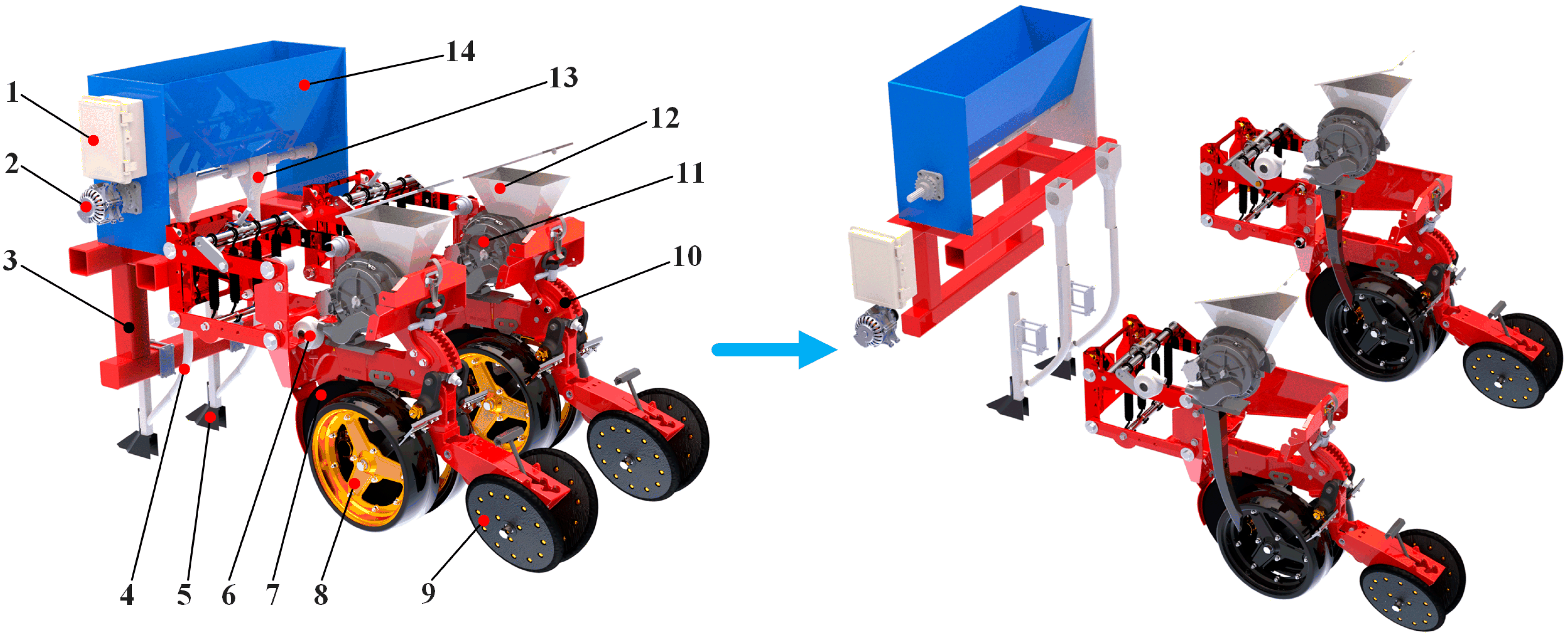
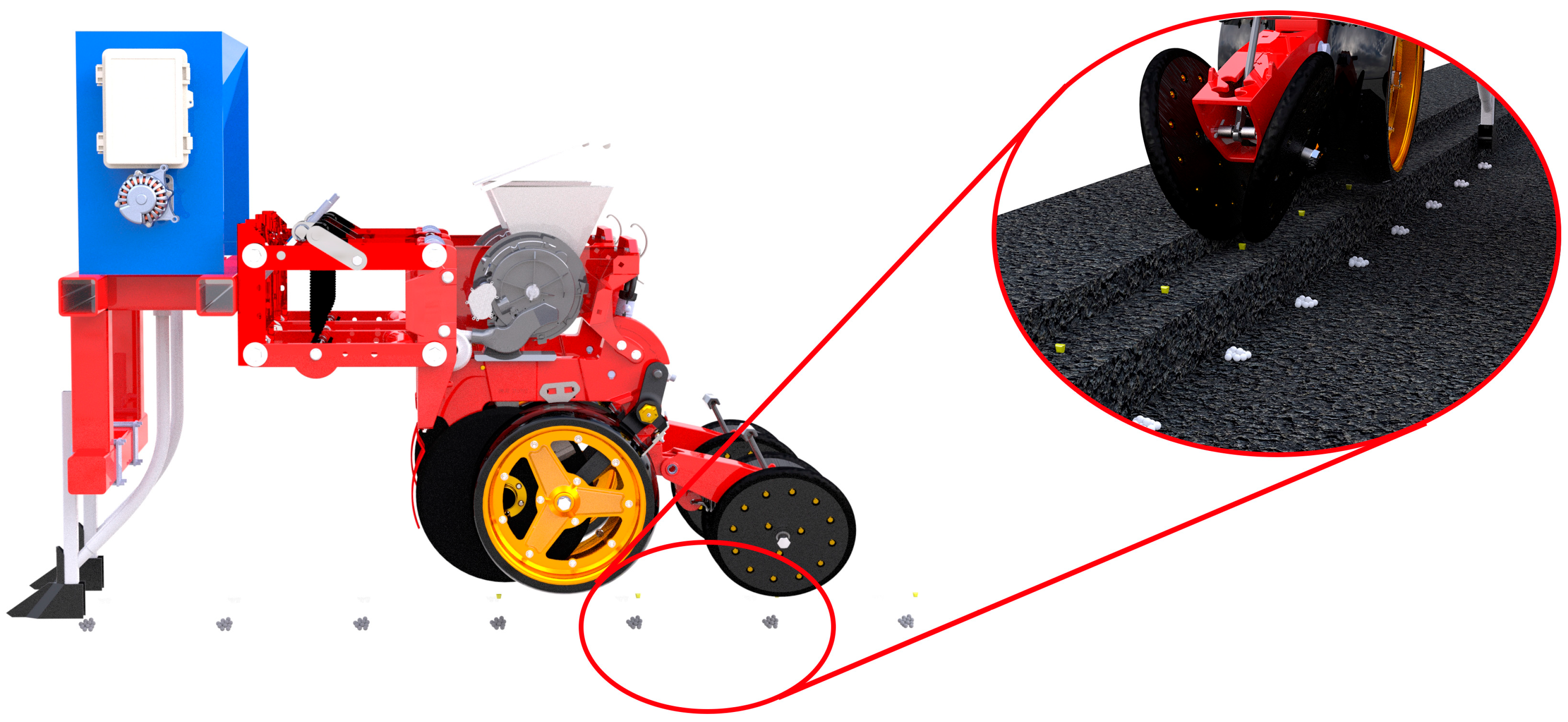
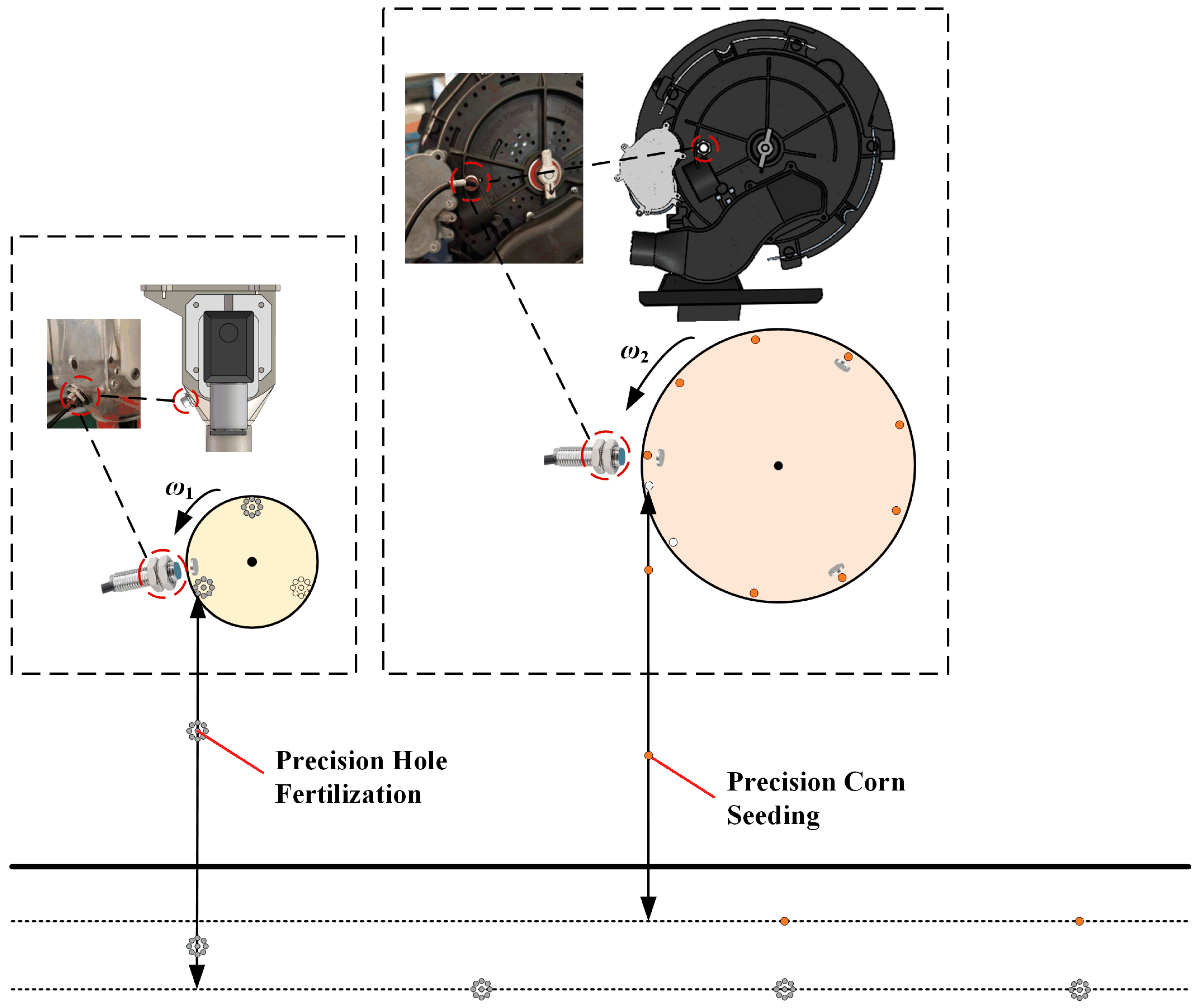
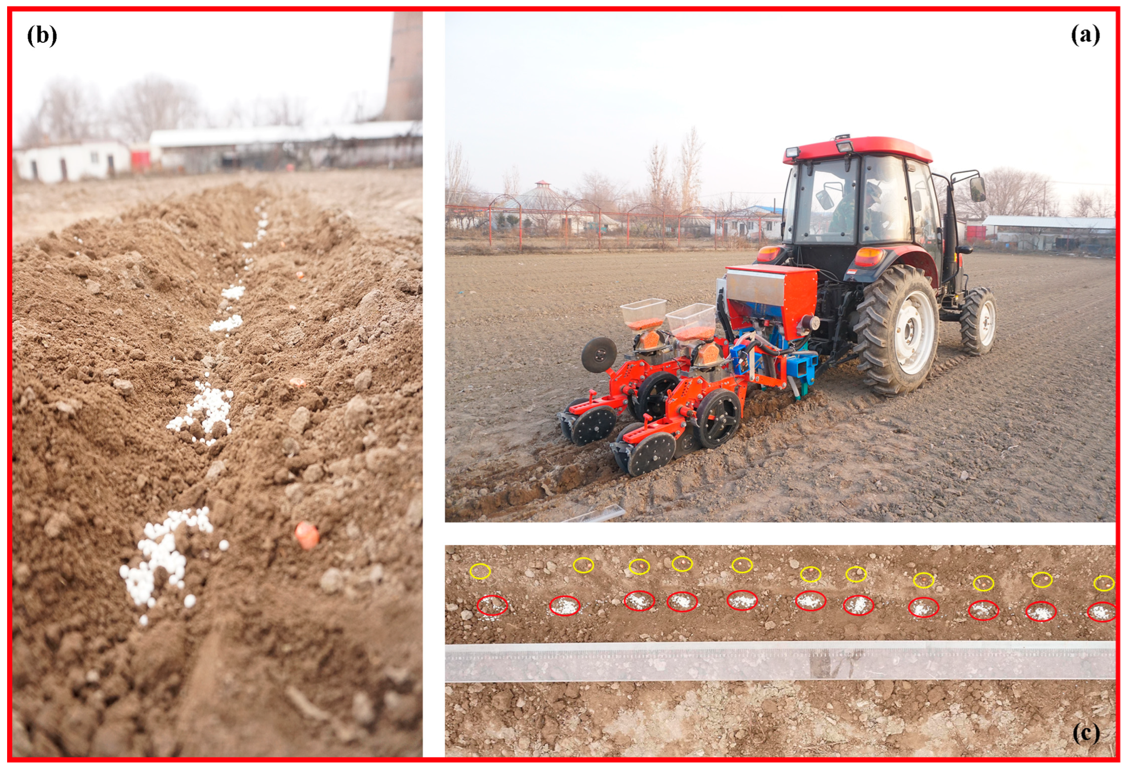
2.2. The Overall Structure and Working Principle of the Corn Seeding Synchronous Hole Fertilization Device

Based on the above agronomic requirements, the research and development of a synchronous hole fertilization device for maize sowing was carried out. The developed synchronous hole fertilization device was mainly composed of an electric drive precision sowing unit, hole fertilization unit, regulation control unit, and rack. The sowing unit is composed of a corn electric drive precision seed metering device, independent negative pressure fan, sowing disk opener, depth-limiting wheel, sowing depth regulator, covering soil pressing wheel, seed box, and so on. The hole fertilization unit is composed of a hole fertilization device, fertilization motor, fertilization opener, fertilizer guide tube, fertilizer box, and so on. The regulating control unit is composed of an information acquisition sensor, controller, drive, and actuator. The structure is shown in Figure 1, and the main technical parameters are shown in Table 2.
The working principle of the corn seeding synchronous hole fertilization device is as follows: The hole fertilization unit is installed in front of the electric drive precision seeding unit, and the two have a certain horizontal spacing to perform fertilization from the corn seed side to the hole. When the device is working, the speed of the electric fertilizer distributor and the seed metering device is set according to the working speed. The fertilizer cluster is extracted from the fertilizer box and channeled into the fertilizer ditch via the fertilizer discharge pipe. The seeding unit utilizes an electric-driven pneumatic metering device to achieve precise corn seeding. The sensor in the fertilizer and seed metering devices is installed at the seed metering and fertilizer discharging positions, and the seed position on the seed metering plate and the fertilizer position on the fertilizer discharging device are detected in real time. The relative position of the seed and the fertilizer in the soil is determined by calculating the information of the seed and the fertilizer. The timing begins when the fertilizer discharger detects the fertilizer signal and stops when the seeding signal is detected. The seeding time of the seed metering device is deduced from the relationship between the position of the seed and the fertilizer. The theoretical value is compared with the actual value, and the actual relative position of the seed and the fertilizer is obtained. When the position of the fertilizer and the seed matches, the seed metering device and the fertilizer applicator run at the same time according to the theoretical speed. Once the fertilizer and seed are properly positioned, the seed metering device and fertilizer applicator function together at the set theoretical speed. In case of a positional mismatch, the controller modifies the seeding motor speed (either increasing or decreasing it). By doing so, it changes the phase difference between the seeding disk and fertilizer applicator, realigning the seed and fertilizer positions to restore synchronization. The working principle of the device is shown in Figure 2.

2.3. Development and Examination of Key Components

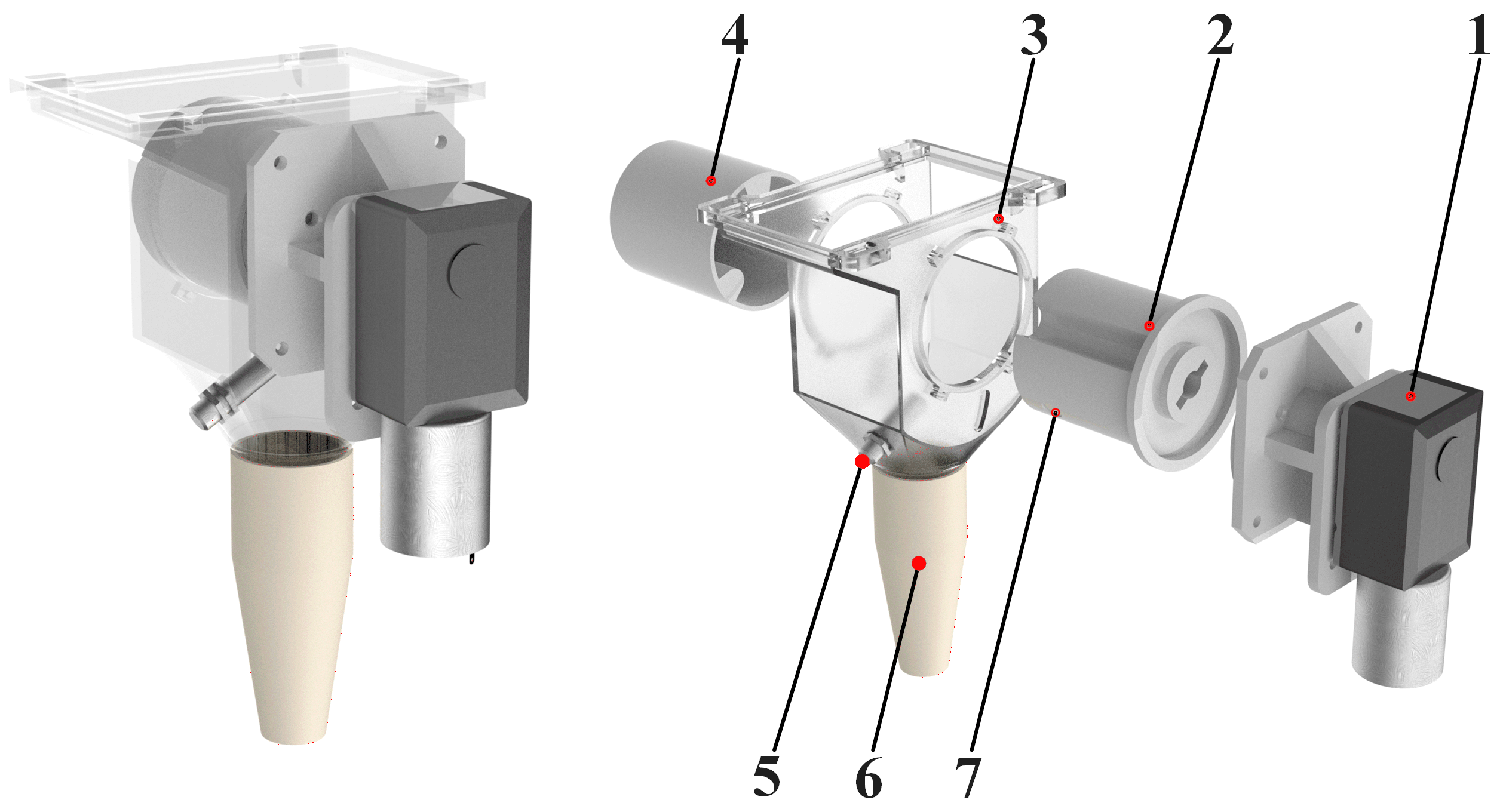
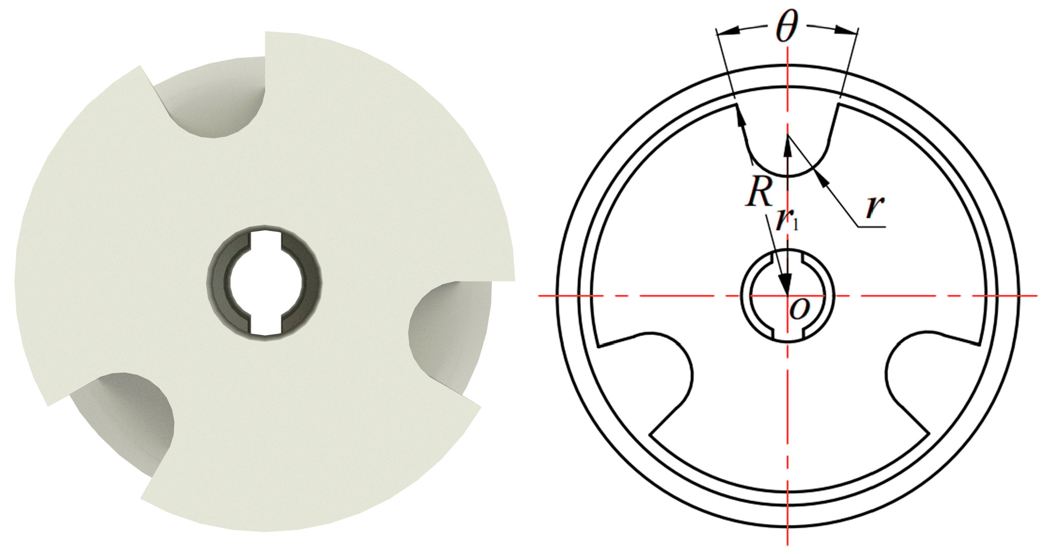
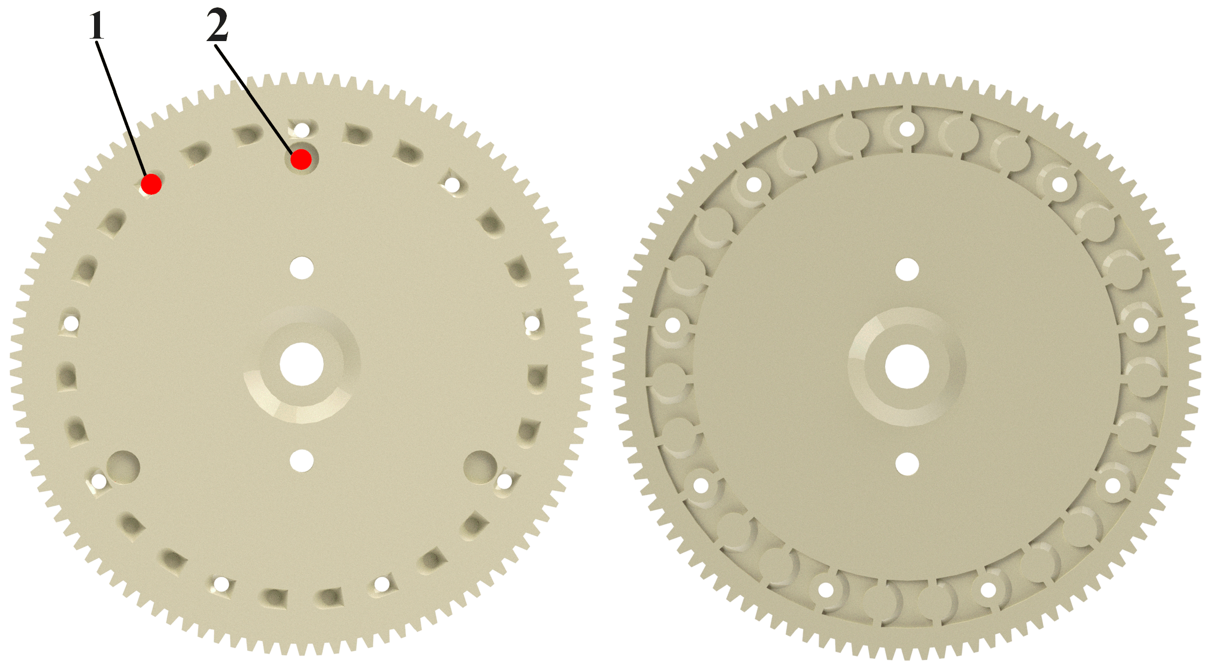
2.3.1. Hole Fertilization Unit

The hole fertilizer apparatus is mainly composed of a shell, an outer groove wheel, a regulator, a brush, a lower fertilizer mouth, and a DC motor, which is fixed and installed at the lower end of the fertilizer box of the machine. The structure of the hole fertilizer apparatus is shown in Figure 3. A circular magnet is installed on the outer groove wheel of the fertilizer apparatus, and a Hall sensor is installed at the corresponding position of the circular magnet and the hole fertilizer apparatus shell. When the outer groove wheel takes, stores, and transports fertilizer to the fertilizer position, the sensor generates an electrical signal and transmits it to the STM32 microcontroller (Guangzhou Xingyi Electronic Technology Co., Ltd. (punctive atom), Guangzhou City, Guangdong Province, China).
On the basis of the fertilizer apparatus developed by the project team in the early stage [24], the performance of the outer groove wheel was improved and optimized. When the outer groove wheel’s diameter is held constant, factors such as the grain distance and the speed of the machine are comprehensively considered. If there are fewer grooves, the speed of the outer groove wheel is faster, which makes it difficult for the fertilizer to be taken in sufficient time, so the fertilizer is dumped. If there are too many grooves, the width of the groove is too small, which has a great influence on the hole fertilization performance of the device. At the same time, the fertilizer storage capacity of the whole groove cannot meet the growth demand of a single corn plant. Based on the preliminary experimental results of the project group [25,26], there were three grooves, the radius of the groove wheel R was 34 mm, and the arc center distance r1 was 25 mm. The angle θ of a single groove was designed to be 30°, and the grooves were evenly distributed on the groove wheel. The correlation model of the outer groove wheel section is established, as shown in Figure 4.
The calculation formula of the cross-sectional area of a single fertilizer cavity (groove) on the outer groove wheel of the fertilizer distributor is:
r = r 1 · sin θ 2
S = θ 360 π R 2 r 1 2 · sin θ 2 · cos θ 2 + 1 2 θ 360 · π r 2
where θ is the angle of a single groove (°), r1 is the arc center distance (mm), r is the radius of the bottom circle of the groove (mm), R is the radius of the groove wheel (mm), and S is the cross-sectional area of a single groove (mm2).
The cross-sectional area S of a single groove can be calculated to be 201.02 mm2 by Formulas (1) and (2). The fertilizer selected in the experiment is a slow-release compound fertilizer. The fertilizer particles are basically spherical (radius r0 is about 1.6 mm), and the thousand grain mass m0 is 62.5g; from Table 1 (agronomic parameters of different maize varieties), it can be seen that the target fertilization amount mx of a single hole is 2~6 g, and the volume range of fertilizer particles Vx corresponding to the target fertilization amount of a single hole is 548.8~1646.4 mm3.
l = V x S
where l is the effective filling length of a single groove during fertilizer discharge operation (mm), Vx is the volume of fertilizer particles per hole corresponding to the target fertilization amount of a single hole (mm3), and S is the cross-sectional area of a single groove (mm2).
Formula (3) can be used to calculate the effective length of a single groove (filling fertilizer length) in the range of 2.73~8.19 mm.

2.3.2. Sowing Unit

The seeding unit adopts the air suction precision seed metering device [27,28] developed by the project team in the early stage and is widely used. It is mainly composed of a seed metering plate, seed cleaning mechanism, driving motor and encoder, reducer, Hall sensor, seed guide tube, and other parts. The structure is shown in Figure 5.
Based on the air suction precision seed metering device developed by the project team, the seed metering plate was improved. According to a preliminary experiment on seed taking, the seed hole diameter of the seed plate was set at 4.5 mm in the design, the number of seed holes was set to 9, and the disk-shaped magnet was installed directly below the seed hole. The Hall sensor was installed at the corresponding position of the seed plate and the seeding monomer shell. When the seed plate sucks seeds and the seeds follow the seed plate to where the negative pressure disappears, when responding to stimuli, the sensor develops electrical signals and routes them to the STM32 microcontroller. The structure is shown in Figure 6.

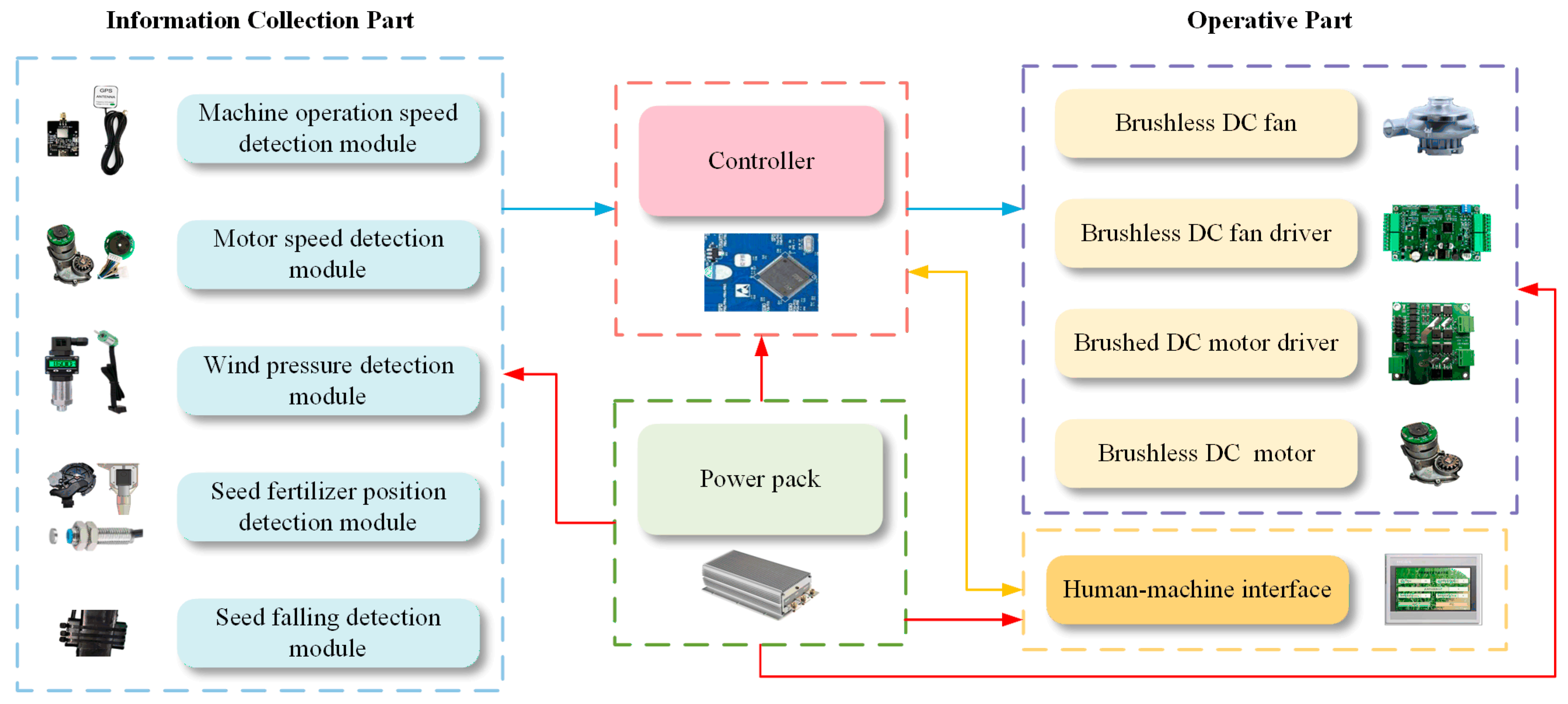
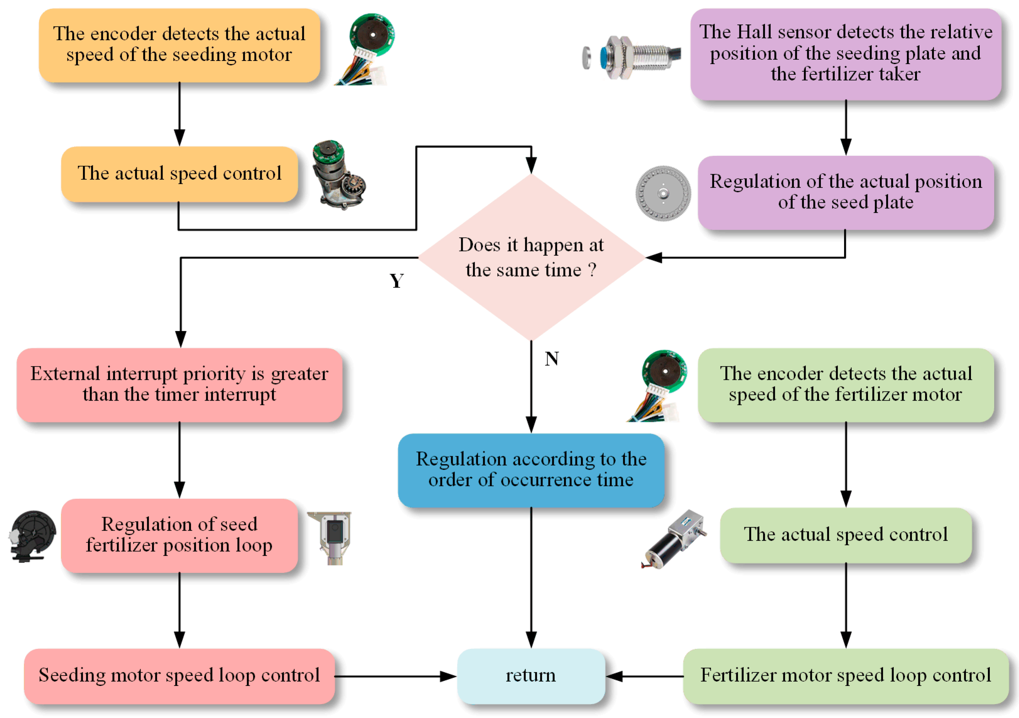
2.3.3. Control System Unit

The control system hardware architecture consists of six integrated components (Figure 7): (1) An STM32 microcontroller serving as the central controller; (2) an information acquisition module monitoring motor speeds (fertilization and seeding); (3) operational status signals (fertilizer and seeding) and machine velocity; (4) a touch screen interface for human–machine interaction, and a drive execution unit comprising DC motor drivers and actuators for the groove wheel fertilizer dispenser and air suction seed metering device; (5) a fan module providing negative pressure for the seed metering device; (6) a power supply module ensuring stable voltage regulation. The microcontroller processes sensor inputs and touch screen commands in real time, generating precision control signals that drive the execution motors while the touch screen displays system feedback, forming a closed-loop control system for synchronous fertilization and seeding operations.
The hardware of the control system incorporates several functional circuits, with the STM32 microcontroller core circuit included, encoder interface, Hall effect speed measurement system (utilizing Juhua Technology’s STM8-P12/545-P16 AB-phase encoders with a 3–24 V operating range, Hangzhou City, Zhejiang Province, China), power regulation circuits (12 V-to-5 V and 5 V-to-3.3 V DC/DC conversion), and satellite speed measurement via an HS6602-485 GPS/BeiDou module (0.1 m/s accuracy, 1–10 Hz update rate). Seed and fertilizer monitoring is implemented through magnetic markers on the seed plate and outer groove wheel detected by Hall sensors, while motor speed is measured via Hall encoders converting angular velocity to AB-phase quadrature signals. The system features JTAG debugging interfaces, LED indication circuits, and USB serial communication interfaces, with all sensor data transmitted through the Modbus protocol at up to 115,200 bps, providing precise real-time control capabilities for the fertilization–seeding synchronization system (Figure 8).
Control system hardware integration: According to the above selection of the information acquisition part, drive and execution part, controller, fan and power supply, and the design of the hardware circuit of the control system, the hardware integration of the control system can be completed, as shown in Figure 9.
According to the overall hardware design and control strategy of the control system, the software design of the control system is carried out, which mainly completes the design of the upper computer interface and the writing of the lower computer program. Keil 5 software is used to develop the control program in the C programming language. It mainly includes the operation speed detection program, the touch screen communication program, the speed detection program of the seeding and fertilization motor, the relative position detection program of the seed fertilizer, and the falling seed detection program. The development of the upper computer interface uses the MCGSPro software (MCGSPro 3.3.6 version) supported by the Kunlun on-state touch screen, that is, the interface for setting and displaying the operating parameters. The overall structural diagram of the software is shown in Figure 10.
Relative position detection of the seed fertilizer: When the magnet on the outer groove wheel is close to the Hall magnetic induction sensor installed on the fertilizer distributor shell, the output signal of the Hall magnetic induction sensor changes, and the position information of the fertilizer on the groove of the outer groove wheel is obtained. When the I/O port level changes, the STM32 single-chip microcomputer starts timing. In the same way, when the magnet on the seeding plate is close to the Hall magnetic induction sensor installed on the seed metering device, the position information of the seed hole of the seeding plate is obtained. When the controller receives the corresponding I/O port level change and finishes timing, the actual interval of seeding and fertilizing time can be obtained. Comparing the theoretical time interval of fertilizer seeding with the actual time interval, the error of the relative position of the seed fertilizer can be obtained.
Design of precise simultaneous broadcast driver of seed fertilizer: The fertilization motor is on the front of the machine. The theoretical speed is obtained according to the working speed of the machine, and the theoretical speed is adjusted. The seeding motor is inside and at the back of the machine. On the one hand, the theoretical speed of the seeding motor is calculated according to the working speed of the machine, and the theoretical speed of the seeding motor is regulated. On the other hand, according to the information on seeding and fertilizing, the real-time mutual positional relationship between the outer groove wheel and the seeding plate is regulated. The rotation speed of the fertilizer metering motor is reduced by the reducer and reflected in the rotation speed of the outer groove wheel and the metering plate. The stability of the rotation speed of the outer groove wheel and the metering plate can also reflect the stability of the fertilizer metering. By detecting the positional relationship between the outer groove wheel and the metering plate, the position of the metering plate relative to the outer groove wheel is slightly regulated; that is, the timing of the outer groove wheel groove fertilizer and the metering plate is regulated, and the one-to-one correspondence of the ground fertilizer position can be realized. The Hall sensor and photoelectric encoder are calibrated by mechanical magnetic markers, and the influence of field vibration is alleviated by mechanical damping and software filtering. The schematic diagram of the fertilizer position regulation is shown in Figure 11.
The position loop control of the seeding motor is carried out by an external interrupter, and the speed loop of the seeding motor is regulated by the timer count. In this way, double closed-loop control of the seeding motor is carried out. Because the priority of the external interrupter of the single-chip microcomputer is higher than the priority of the timer, when the speed loop and position loop occur at the same time, the control system will first carry out position loop control and then carry out speed loop control. The position loop is based on the position of the outer slot wheel to control the position of the seeding plate, and the speed loop controls the speed of the fertilizer seeding motor. The frequency of the system speed loop control is higher than that of the position loop control. The flow chart of double-loop control of the seeding motor is shown in Figure 12.

2.4. Field Test Materials and Conditions

In order to further study the influence of a complex field environment and multi-agronomic demand conditions on the operational performance of the corn seeding synchronous hole fertilization device and the stability of the seed–fertilizer alignment control system based on an STM32 single-chip microcomputer, a field experiment was carried out in the special experimental field for agricultural machinery equipment of Xinjiang Academy of Agricultural and Reclamation Science in October 2024. The field experiment setup is shown in Figure 13.
Xinyu No. 9 hybrid corn seed was the material used in the field sowing synchronous hole fertilization experiment, produced by the Crop Research Institute of XAARS. The moisture level stood at 9.1%, the purity at 98.75%, and the 1000 kernel weight at (274.22 ± 2.5) g. A random sample of 300 kernels was assessed. The kernels had a horse tooth shape, with length, width, and height dimensions of (10.04 ± 1.06) mm, (7.45 ± 0.8) mm, and (5.50 ± 1.01) mm, respectively. The slow-release fertilizer (N:P2O5:K2O = 15:15:15) produced by Zhongnong Group was selected as the fertilizer. The fertilizer particles were basically spherical, and the thousand grain weight was 62.5 g. Other test equipment were: (1) electronic digital display vernier caliper (model: Mitutoyo 500-197-30, range: 0~200 mm, accuracy: 0.01 mm); (2) organic glass ruler (model: Jinsihou NO.81150, measuring range: 0~150 cm, accuracy: 1 mm); (3) electronic precision balance (model: BSM-520.3, range: 0~520 g, accuracy: 0.001 g).

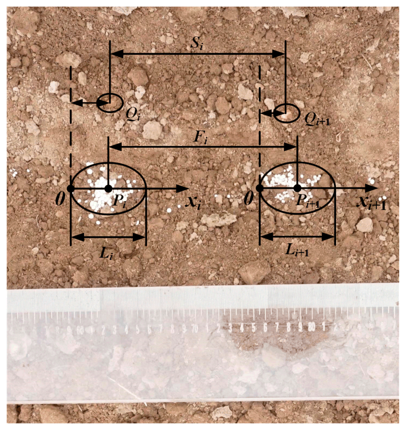
2.5. Field Experiment Design and Evaluation Index

We aimed to adapt the synchronous hole fertilization device developed by the project team to the synchronous operation requirements of seeds and fertilizers for various types of corn (ordinary corn, silage corn, popcorn, etc., in Table 1) and to explore how various key machine parameters impact the synchronous hole fertilization quality, in line with the Box–Behnken experimental design principle and by integrating prior theoretical analysis and preliminary experimental data. The implemented forward speed (A) (specific range of 3~7 km/h), per-hole target fertilizing amount (B) (specific range of 2~6 g), and plant spacing (fertilizer hole interval) (C) (specific range of 16~30 cm), which affect the quality of synchronous hole fertilization, are selected as the experimental factors. At the same time, the range of each variable factor is determined according to the actual agronomic needs of multi-variety maize varieties. The seed–fertilizer alignment qualification rate (Y1) and the coefficient of variation for hole fertilizing amount (Y2) were used as evaluation indexes. The synchronous operation of the seed and fertilizer within 10 m in two rows and in an asymmetric area was evaluated. According to high-level papers related to seed and fertilizer co-sowing [15,16,17,18,29], the determination method of the evaluation index in this experiment was selected, as shown in Figure 14. The response surface software Design Expert 10.0.3 was used to design the factor levels, and a three-factor and three-level orthogonal test was carried out to obtain the conditions for the best qualified rate of the synchronous operation of the seed and fertilizer (Y1) and the coefficient of variation in the hole fertilizer amount (Y2). The factors were coded as shown in Table 3. Each test group was replicated three times, with the mean value serving as the test outcome.
Determination method of qualified rate of seed fertilizer (Y1): The point with the densest fertilizer accumulation in each hole was the center point (Pi), and the corresponding point was the corn seed falling point (Qi). The length of most scattered fertilizer particles was measured as the hole length (Li). The distance between the center points of fertilizer accumulation in two adjacent holes was the hole distance (Fi). The distance between the center points of two adjacent seeds was the plant spacing (Si). Taking the linear direction of the fertilizer distribution in each hole as the coordinate axis (such as the x-axis), the starting point of fertilizer distribution was set as the origin O, and the corresponding point of the i-th corn seed on the coordinate axis was Qi. When the deviation between the position of the seed fertilizer and the target plant spacing (fertilizer hole spacing) does not exceed 2 cm and the seeds that meet the i-th point at the same time are within the corresponding fertilizer distribution range, the seed fertilizer is qualified for the point. If the opposite is true, it is disqualified. The conditions for the i-point fertilizer to be qualified are shown in Formula (4):
S i L target 2   cm F i F target 2   cm 0 Q i L i
where Si is the distance between the center points of two adjacent seeds—the plant spacing; Fi is the distance between the center points of fertilizer accumulation in two adjacent holes; Qi is the coordinate point of the position of the i-th corn seed; Li is the fertilizer distribution length of the i-th hole; and Ltarget (Ftarget) is the target plant spacing (fertilizer hole spacing).
Y 1 = K H K × 100 %
where Y1 is the seed–fertilizer alignment qualification rate, K is the total number of seed–fertilizer pairs in the test measurement area, and H is the total number of disqualified seed–fertilizer pairs in the test measurement area.
Determination method of the coefficient of variation in the hole fertilizing amount (Y2): Taking the point with the densest fertilizer accumulation in each hole as the center point, the number of fertilizer particles around the center point was counted. In order to avoid the influence of soil and other environmental factors on the weight of the fertilizer, the same number of particles was randomly selected from the fertilizer bag to replace the fertilizer particles in the soil for weighing, and was used to calculate the actual fertilization amount of each hole.
m μ = i = 1 N m a i N
Y 2 = C V = 1 N i = 1 N m a i m μ m μ × 100 %
where Y2 is the coefficient of variation in the hole fertilizing amount; mai is the actual fertilization weight of the ith hole; N is the total number of holes fertilized in the experimental measurement area; and mμ is the arithmetic average of the actual fertilization weight of each hole in the experimental measurement area.

3. Results and Discussion

3.1. Response Surface Design and Results

The field orthogonal test results based on the above design scheme are shown in Table 4, including 12 analysis factors and 5 coordinate origin tests for estimating errors.

3.2. Y1 and Y2 Model Establishment and Variance Analysis

The Design Expert 10.0.3 software was utilized for multiple regression fits on Table 4’s test data. Variables A, B, and C corresponded to the implemented forward speed, per-hole target fertilizing amount, and plant spacing (fertilizer hole interval). Y1 (seed–fertilizer alignment qualification rate) and Y2 (coefficient of variation in hole fertilizing amount) served as response values for the regression fit, establishing a regression model linking the influencing factors to the evaluation indexes. The details are in Formulas (8) and (9), and the regression coefficients along with the significance test results are in Table 5.
Y 1 = 91.91 2.5     A 0.75     B + 2.08     C 0.69     A B 0.69     A C 0.12     B C 0.94     A 2 2.73     B 2 1.09     C 2
Y 2 = 4.87 0.67     A 1.56     B 2.41     C + 0.92     A B 0.34     A C 0.79     B C + 1.91     A 2 + 3.13     B 2 + 0.38     C 2
The F test and analysis of variance (ANOVA) were performed on the regression coefficients in the regression models of evaluation indicators Y1 and Y2, and the results are shown in Table 4. According to the significance value P of the regression model, PL1 = 0.4550 > 0.05 and PL2 = 0.4096 > 0.05 (neither are significant) for the objective functions Y1 and Y2 in Table 4; this indicates that the two models fit the data adequately, with no major omissions in the regression analysis. The models align closely with the actual test results; the P value for the model’s regression term is highly significant, PM1 < 0.0001 and PM2 < 0.0001, indicating that the regression results have a certain reliability.
From the ANOVA, we can find out the significance value P for each factor that has an influence on the experiment. For evaluation index Y1, factors A, B, and C had extremely significant effects, and the quadratic interactions AB and AC had significant effects. For evaluation index Y2, factors B and C had extremely significant effects, factor A had significant effects, and the quadratic interactions AB and BC had significant effects. The analysis of the F values for each factor in Table 4 reveals that a greater F value corresponds to a stronger influence of that factor on the test index. Consequently, the order of influence on the seed–fertilizer alignment qualification rate Y1 was A > C > B, and the effect of quadratic interaction on the seed–fertilizer alignment qualification rate Y1 was AB > AC > BC. The hierarchy of influence of each test factor on the coefficient of variation in the hole fertilizing amount Y2 for hole fertilization was C > B > A; the effect of quadratic interaction on the coefficient of variation in the hole fertilizing amount Y2 of hole fertilization was AB > BC > AC.

3.3. The Influence of Factor Interactions on the Evaluation Index

To express the interaction effects of various factors on the qualified rate of seed and fertilizer, Y1, and the coefficient of variation in hole fertilization, Y2, the quadratic regression equation of the above two evaluation indexes was reduced in dimension.
One factor was fixed at the 0 level, and interaction effects between the other two factors were analyzed, excluding insignificant interactions (such as the BC interaction for Y1 and the AC interaction for Y2). The impacts of the AB and AC interactions on Y1, and the AB and BC interactions on Y2, were then assessed, and corresponding response surfaces were generated.

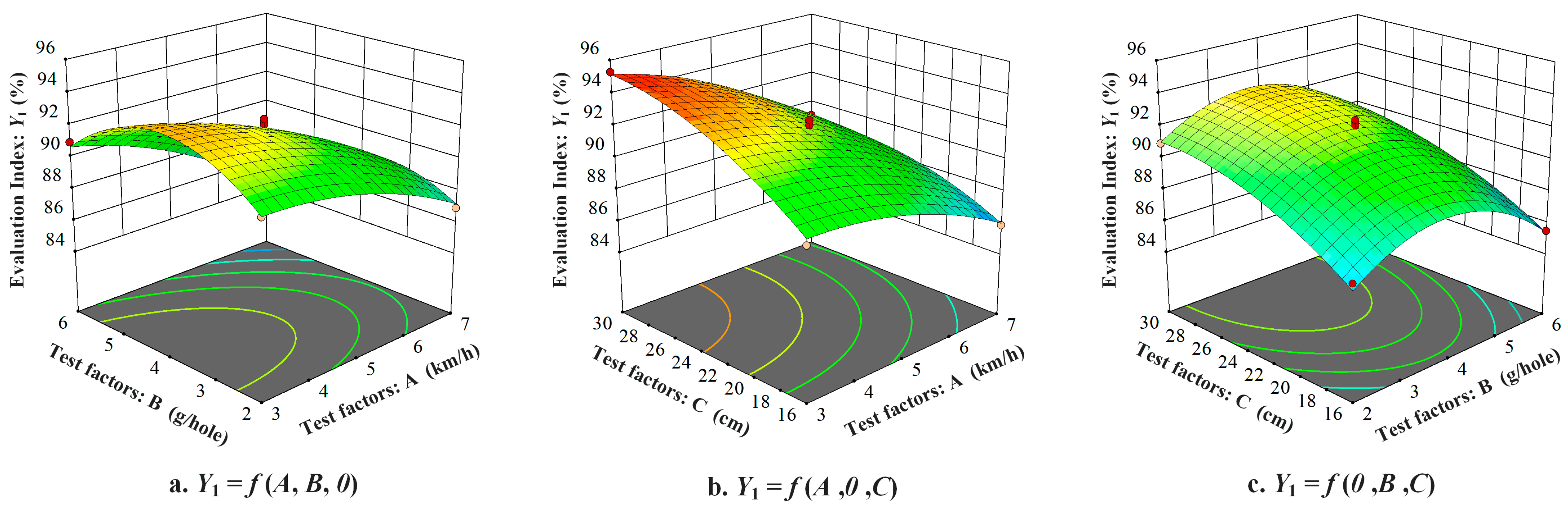
3.3.1. The Effect on the Seed–Fertilizer Alignment Qualification Rate Y1

In the intuitive diagram of the response surface interaction shown in Figure 15a, when the plant spacing C (fertilizer hole interval) is at the zero level, the influence of the interaction between the implemented forward speed A and per-hole target fertilizing amount B on the seed–fertilizer alignment qualification rate Y1 has an arched surface distribution. The seed–fertilizer alignment qualification rate Y1 decreased with the increase in random advance speed A, and the seed–fertilizer alignment qualification rate Y1 increased first and then decreased with the increase in single-hole target fertilization B. When the forward speed A of the machine was different, the seed–fertilizer alignment qualification rate Y1 varied with the increase in single-hole target fertilization B, which indicated that there was a significant interaction between the forward speed A of the machine and the single-hole target fertilization B. By contrast, the longitudinal span of the response surface changed greatly in the direction of the forward speed A of the machine. The results showed that the influence of the forward speed A of the factor machine on the seed–fertilizer alignment qualification rate Y1 was greater than that of the single-hole target fertilization amount B. The reason is that when the single-hole target fertilization amount B is small, the fertilizer discharger will produce a composting phenomenon; when the forward speed A of the machine is high, the performance of the fertilizer discharger decreases, which eventually leads to a decrease in the seed–fertilizer alignment qualification rate Y1. Therefore, when the forward speed A of the machine is 3~5 km/h and the seed–fertilizer alignment qualification rate Y1 is combined in the 3~5 g level interval, the qualified rate of synchronous operation of the seed and fertilizer can be significantly improved.
In the intuitive response surface interaction diagram shown in Figure 15b, when the single-hole target fertilization amount B is at the zero level, with the increase in the forward speed A of the machine, the seed–fertilizer alignment qualification rate Y1 decreases slowly. When the forward speed A of the machine is small, with the increase in plant spacing C (fertilizer hole spacing), the seed–fertilizer alignment qualification rate Y1 increases linearly. When the forward speed A of the machine is large, with the increase in plant spacing C (fertilizer hole spacing), the seed–fertilizer alignment qualification rate Y1 increases first and then tends to be gentle. This suggests a significant interaction between factor A (machine forward speed) and factor C (plant spacing, i.e., fertilizer hole spacing). Meanwhile, the longitudinal span of the response surface in the B direction (single-hole target fertilization amount) varies greatly, which demonstrates that factor C (plant spacing, i.e., fertilizer hole spacing) has a more substantial impact on the seed–fertilizer alignment qualification rate Y1 than the machine’s forward speed does. Considering only the interaction between the two, the optimized parameter conditions of the seed–fertilizer alignment qualification rate Y1 are concentrated in the combination of a machine forward speed of 3~5 km/h and a plant spacing (fertilizer hole spacing) in the range of 26~30 cm.

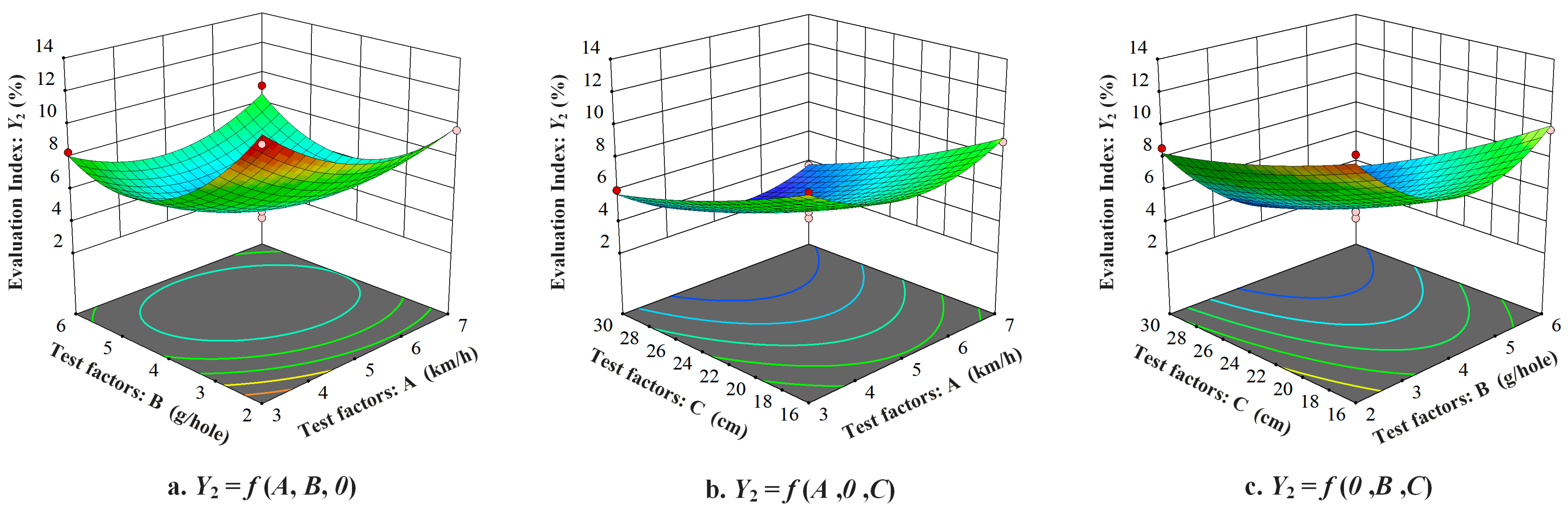
3.3.2. Effect on the Coefficient of Variation in Hole Fertilizing Amount Y2

The influence of the interaction between the implemented forward speed A and the per-hole target fertilizing amount B on the coefficient of variation in the hole fertilizing amount Y2 is shown in Figure 16a. On the AB interaction surface, the slope of the coefficient of variation in the hole fertilizing amount Y2 decreases first and then increases with the increase in the single-hole target fertilization amount B. With the increase in the forward speed of the machine A, the coefficient of variation in the hole fertilizing amount Y2 decreases first and then increases, and when the single-hole target fertilization amount B differs, the coefficient of variation in the hole fertilizing amount Y2 varies with the increase in the forward speed A of the machine. This shows that the forward speed A of the machine and the target fertilization amount B of a single hole have a significant interaction effect on the coefficient of variation in the hole fertilizing amount Y2. Under the condition of only considering the interaction between the two, when the forward speed A of the machine is in the range of 4~6 km/h and the target fertilization amount B of a single hole is in the range of 3~5 g, the coefficient of variation in the hole fertilizing amount Y2 reaches the minimum value, and the results of surface variance analysis in Figure 15 and Table 5 are also consistent.
The effect of the interaction between the per-hole target fertilizing amount B and the plant spacing C (fertilizer hole interval) on the coefficient of variation in the hole fertilizing amount Y2 is shown in Figure 16b. On the BC interaction surface, the variation slope of the coefficient of variation in the hole fertilizing amount Y2 decreases with the increase in the plant spacing C (fertilizer hole interval). When the plant spacing C (fertilizer hole interval) is small, the variation slope of the coefficient of variation in the hole fertilizing amount Y2 decreases first and then increases with the increase in the per-hole target fertilizing amount B. When the plant spacing C (fertilizer hole interval) is large, the coefficient of variation Y2 of the fertilizer application rate in the hole of the slope decreases slowly and then levels off with the increase in the per-hole target fertilizing amount B, which indicates that there was a significant interaction between plant spacing C (fertilizer hole interval) and the per-hole target fertilizing amount B. Considering only the interaction between the two, the coefficient of variation in the hole fertilizing amount Y2 applied per hole is 3~5 g, and the plant spacing C (fertilizer hole interval) is 26~30 cm. The maximum value is obtained. By contrast, the coefficient of variation in the amount of fertilizer applied in the hole fluctuates greatly in the direction of plant spacing (fertilizer hole interval), indicating that the effect of plant spacing (fertilizer hole interval) C on the coefficient of variation in the fertilizer applied in the hole Y2 is greater than that of single-hole target fertilization B.

3.4. Comprehensive Optimization Design and Verification of Experiment Results

According to the regression equation model, the maximum qualified rate of synchronous operation of the seed and fertilizer device and the maximum coefficient of variation in hole application were taken as the optimization objectives. The optimal conditions for prediction were as follows: the forward speed of the machine was 4.149 km/h, the target fertilization amount of a single hole was 4.379 g, and the plant spacing (fertilizer hole spacing) was 30 cm. According to the actual conditions of the experiment, under optimal conditions (forward speed of machine, 4.2 km/h; target fertilization amount of a single hole, 4.4 g; plant spacing, 30 cm), after three parallel experiments, the actual qualified rate of synchronous operation of the seed and fertilizer was 94.024 ± 0.694%, and the coefficient of variation in hole fertilization was 3.147 ± 0.058%. The field experiment scene is shown in Figure 17. The qualified rate of synchronous operation with the predicted total seed fertilizer was 93.878%, and the variation coefficient of hole application was 3.212%. The difference was within 5%, which confirmed the good correlation between the predicted value and the experimental value, indicating that the optimal machine parameters obtained by the response surface method were reasonable.

3.5. Discussion—Innovations and Comparisons with Other Solutions

(1) When the machine speed was 4.0~4.5 km/h, the single hole fertilization amount was 4.0~5.0 g, the plant spacing was 28~30 cm, the qualified rate of seed and fertilizer was more than 92%, and the coefficient of variation was less than 4%. At the same time, combined with the multi-source data of Table 1 (agronomic parameters of different maize varieties) and Table 4 (test schemes and results), it can be verified that the corn seeding synchronous hole fertilization device designed in this study can meet high-quality operation requirements under the combination of different agronomic parameters of various maize varieties (that is, the qualified rate of seed–fertilizer alignment was >84.3%, and the coefficient of variation in hole fertilization amount was <12.54%). Other seed and fertilizer synchronous operation devices of the same type can only meet high-quality operation requirements under specific and single conditions, cannot adapt to the operation requirements of multi-agronomic parameters, and the adaptability of those devices is weak.
(2) This device realizes the real-time seed and fertilizer phase adjustment of a double closed-loop control system (position loop > speed loop) for the first time, and the alignment accuracy is improved by 12~15% compared with other schemes. At the same time, compared with the traditional strip fertilization method, the amount of fertilizer required for maize by the hole fertilization method in this study was only 480 kg/hm2 under the same production mode. The amount of fertilizer required for corn using the traditional strip fertilization method is 750 kg/hm2; our device saves about 36% of fertilizer, and shows significant advantages in improving fertilizer utilization, reducing fertilizer application, reducing production costs, and reducing soil hardening degradation and water pollution.
To sum up, the field testing outcomes of the corn sowing synchronous hole fertilization device developed in this study align with practical operation demands, and the device has been verified by experiments to complete the synchronous field operation of seed and fertilizer under the requirements of different agronomic parameters of various types of corn (ordinary corn, silage corn, popcorn, etc.) with high quality. This shows that the seeding synchronous hole fertilization device designed by the project team has good working performance, realizes the precise matching hole fertilization of corn sowing, provides equipment and technical support for the precise fertilization of corn, and has certain reference value.

4. Conclusions and Prospects

4.1. Conclusions

In this study, a synchronous hole fertilization device for maize sowing and its real-time intelligent control system for precision agriculture were designed and verified to meet the needs of precision fertilization for maize, and the precise application of seeds and fertilizers was realized. Through response surface optimization, ANOVA, and field trials, we can draw the following conclusions:
(1) Design of key parameters of precision hole fertilization unit: The three groove parameters of the optimized design hole fertilization device were used. The groove cross-sectional area and the filling length were theoretically calculated and experimentally verified (the effective filling length range was 2.73~8.19 mm), which ensured the accuracy and adjustability of the single hole fertilization amount (target 2~6 g) and met the needs of different maize varieties.
(2) The order of primary and secondary factors affecting the seed–fertilizer alignment qualification rate Y1 was machine forward speed A > plant spacing C (fertilizer hole spacing) > per-hole target fertilizing amount B; the effect of quadratic interaction on the seed–fertilizer alignment qualification rate Y1 was AB > AC > BC. The order of primary and secondary factors affecting the coefficient of variation in the hole fertilizing amount Y2 was plant spacing C (fertilizer hole spacing) > per-hole target fertilizing amount B > machine forward speed A; the effect of quadratic interaction on the coefficient of variation in the hole fertilizing amount (Y2) was AB > BC > AC.
(3) The field experiment was optimized using the Box–Behnken response surface method. Under the parameter combination of a forward speed of 4.2 km/h, a per-hole target fertilizing amount of 4.4 g, and a plant spacing (hole spacing) of 30 cm, the seed–fertilizer alignment qualification rate was as high as 94.024 ± 0.694%, which was significantly better than the traditional strip application method. At the same time, the coefficient of variation in the amount of fertilizer applied to the hole was as low as 3.147 ± 0.058%, indicating that the device had an excellent uniformity of fertilization and effectively reduced the fluctuation in the amount of fertilizer applied to the hole.
(4) By adjusting parameters such as plant spacing, fertilization depth, and fertilization amount, the device can effectively meet the specific agronomic requirements of common corn, silage corn, popcorn, and other corn varieties for different purposes (according to the parameters in Table 1), which proves its good regional adaptability and multi-purpose compatibility.
In summary, the device performs well in precision alignment, fertilization uniformity, multi-environmental adaptability, and multi-corn species compatibility. It can perform hole fertilization according to corn fertilizer demand. The field test verification was remarkable. Compared with the traditional strip fertilization method, it is more concentrated and can effectively improve the fertilizer utilization rate, reduce the amount of chemical fertilizer applied, reduce the production cost, and reduce soil hardening degradation and water pollution. The device provides technical support for promoting the precise, high-efficiency, and green development of corn planting.

4.2. Prospects

Future research will conduct an in-depth exploration of maize sowing synchronous hole fertilization devices in multiple key areas. First, we will expand the scope of the experiment to cover a more diverse field environment, including different topographic features (such as plains and hills) and different soil conditions (such as soil compaction, water content, texture, and fertility). Through extensive experiments in these complex environments, we strive to verify and optimize the adaptability and reliability of the device to ensure that it can operate stably and maintain efficient fertilization performance in various actual agricultural production scenarios.
Secondly, regarding the energy consumption characteristics of the device under different operating modes, we will carry out systematic power consumption evaluation research. The energy consumption per unit area of the measuring device under different working speeds, seeding density, and fertilization amounts will be determined, as well as the energy consumption changes during dynamic operations such as acceleration, deceleration, and turning. This will help us to fully understand the energy efficiency performance of the device and provide key economic and feasibility data support for its application in large-scale agricultural production.
In addition, we will also focus on the durability and maintenance requirements of key components of the device. Through research of mechanical stress analysis, wear prediction, and life assessment, we expect to develop a scientific and reasonable maintenance plan and parts replacement cycle, reducing the long-term operating cost of the equipment and prolonging its service life. The preliminary plan is to use finite element analysis (FEA) and other methods to evaluate the mechanical properties of the main components such as the fertilizer applicator, fertilizer motor, and seeding motor. Combined with the wear monitoring data under actual working conditions, the life of the main components under different service strengths can be predicted, and the design parameters and material selection can be optimized accordingly.
In general, through the in-depth study of the above aspects, we are committed to continuously improving the comprehensive performance of the maize sowing synchronous hole fertilization device, making it more intelligent, efficient, and adaptable, so as to provide strong technical support for promoting the precise, high-efficiency, and sustainable development of corn planting, and help modern agriculture move towards a green, low-carbon, and intelligent direction.

Author Contributions

Conceptualization, F.P., Z.F. and C.J.; methodology, F.P., B.W. and J.C.; software, F.P., J.L. and J.C.; validation, F.P., C.J. and K.H.; formal analysis, F.P., B.W. and Z.F.; investigation, F.P. and J.L.; resources, F.P., B.W. and C.J.; data curation, F.P., K.H. and Z.F.; writing—original draft preparation, F.P.; writing—review and editing, F.P. and C.J.; visualization, F.P. and J.L.; supervision, C.J.; project administration, F.P., B.W. and C.J.; funding acquisition, C.J. All authors have read and agreed to the published version of the manuscript.

Funding

This research was funded by the Key Scientific and Technological Projects in Key Areas of the Xinjiang Production and Construction Corps (Nos. 2023AB038, 2020AB011), the Young Science and Technology Top Talent Program of Tianshan Talent Training Program in Xinjiang Province (No. 2022TSYCCX0123), the Projects for extending, supplementing and strengthening the industrial chain (2025CYL04), and the Youth Talent Support Program of Tianshan Talent Training Program in Xinjiang Province, and supported by the Bingtuan Science and Technology Program—technology Program “Xinjiang Academy of Agricultural and Reclamation Science Research Project” (No. 2023YJ013).

Institutional Review Board Statement

Not applicable.

Informed Consent Statement

Not applicable.

Data Availability Statement

The test data are contained within the article. The other original data of this study are the results of the experimental stage, which is still internal data for the team at this stage and has not been publicly archived. When appropriate and in compliance with relevant data sharing policies, we will consider appropriate disclosure and the archiving of relevant data supporting the findings of this study.

Conflicts of Interest

The authors declare no conflicts of interest.

References

  1. Luo, X.; Liao, J.; Hu, L.; Zang, Y.; Zhou, Z. Improving agricultural mechanization level to promote agricultural sustainable development. Trans. Chin. Soc. Agric. Eng. (Trans. CSAE) 2016, 32, 1–11. [Google Scholar] [CrossRef]
  2. Zhang, F.; Wang, J.; Zhang, W.; Cui, Z.; Ma, W.; Chen, X.; Jiang, R. Nutrient Use Efficiencies of Major Cereal Crops in China and Measures for Improvement. Acta Pedol. Sin. 2008, 45, 915–924. [Google Scholar]
  3. Liu, Q. Spatio-temporal changes of fertilization intensity and environmental safety threshold in China. Trans. Chin. Soc. Agric. Eng. (Trans. CSAE) 2017, 33, 214–221. [Google Scholar] [CrossRef]
  4. Zhang, L.; Song, H.; Chen, X.; Lu, D.; Wang, H. Primary Study on Nutrient Migration Under Hole Fertilization in Soils. Soils 2020, 52, 1137–1143. [Google Scholar] [CrossRef]
  5. Wang, Y.; Bai, Y.; Tan, J.; Liu, J.; Lu, Y.; Han, Y. Availability study of once quantitative fertilization in summer maize using fertilizer tablets. J. Plant Nutr. Fertil. 2016, 22, 1126–1132. [Google Scholar] [CrossRef]
  6. Tang, H.; Wang, J.; Xu, C.; Zhou, W.; Wang, J.; Wang, X. Research Progress Analysis on Key Technology of Chemical Fertilizer Reduction and Efficiency Increase. Trans. Chin. Soc. Agric. Mach. 2019, 50, 1–19. [Google Scholar] [CrossRef]
  7. Zhang, X. Research on the Equipment of Hill-drop Drill and Fertilization. Master’s Thesis, Northwest A&F University, Xianyang, China, 2009. [Google Scholar]
  8. Zhang, R. Study on Control System of Synchronous Hole Fertilization for Maize Sowing. Master’s Thesis, Heilongjiang Bayi Agricultural University, Daqing, China, 2023. [Google Scholar]
  9. Liu, Z.; Wang, Q.; Liu, C.; Li, H.; He, J.; Liu, J. Design and Experiment of Precision Hole-fertilizing Apparatus with Notched Plate. Trans. Chin. Soc. Agric. Mach. 2018, 49, 137–144, 355. [Google Scholar] [CrossRef]
  10. Liao, Q.; Chen, Y.; Zhang, Q.; Wang, L.; Lin, J.; Wenbin, D. Design and Experiment of Side Deep Hole Fertilization Device for Rapeseed. Trans. Chin. Soc. Agric. Mach. 2023, 54, 41–52. [Google Scholar] [CrossRef]
  11. Cay, A.; Kocabiyik, H.; May, S. Development of an electro-mechanic control system for seed-metering unit of single seed corn planters Part I: Design and laboratory simulation. Comput. Electron. Agric. 2018, 144, 71–79. [Google Scholar] [CrossRef]
  12. Cay, A.; Kocabiyik, H.; May, S. Development of an electro-mechanic control system for seed-metering unit of single seed corn planters Part II: Field performance. Comput. Electron. Agric. 2018, 145, 11–17. [Google Scholar] [CrossRef]
  13. Yuan, Y.; Bai, H.; Fang, X.; Wang, D.; Zhou, L.; Niu, K. Research Progress on Maize Seeding and Its Measurement and Control Technology. Trans. Chin. Soc. Agric. Mach. 2018, 49, 1–18. [Google Scholar] [CrossRef]
  14. Da Silva, M.J.; Magalhães, P.S.G. Modeling and design of an injection dosing system for site-specific management using liquid fertilizer. Precis. Agric. 2019, 20, 649–662. [Google Scholar] [CrossRef]
  15. Du, X.; Liu, C.; Jiang, M.; Yuan, H.; Dai, L.; Li, F. Design and Experiment of Inclined Trapezoidal Hole Fertilizer Point-applied Discharging Device. Trans. Chin. Soc. Agric. Mach. 2021, 52, 43–53. [Google Scholar] [CrossRef]
  16. Liu, Z.; Wang, X.; Li, S.; Huang, Y.; Yan, X.; Zhao, H. Design of Maize Automatic Hole Fertilization System Targeting at Seed Based on Planetary Gear Train. Trans. Chin. Soc. Agric. Mach. 2023, 54, 60–67. [Google Scholar] [CrossRef]
  17. Liu, Z.; Wang, Q.; Li, H.; He, J.; Lu, C.; Xie, L. Design of Flexible Fertilizer Protection Mechanism for Hole-fertilizing Apparatus with Notched Plate. Trans. Chin. Soc. Agric. Mach. 2018, 49, 97–103. [Google Scholar] [CrossRef]
  18. Li, G.; Su, X.; Zhou, X.; Zhang, X.; Wang, Q.; Wang, C. Design and Experiment of Pneumatic Assisted Hole Fertilization Targeting Seed Position Device. Trans. Chin. Soc. Agric. Mach. 2024, 55, 191–200. [Google Scholar] [CrossRef]
  19. Liu, X.; Wang, X.; Chen, L.; Zhang, C.; Liu, W.; Ding, Y. Design and experiments of layered and quantitative fertilization device for rapeseed seeder. Trans. Chin. Soc. Agric. Eng. 2021, 37, 1–10. [Google Scholar] [CrossRef]
  20. Zhang, Y.; Liu, D.; Xie, F.; Zheng, P.; Song, S. Parameter optimization of spiral inclined fertilization device and its trial for rice side deep fertilization. J. Hunan Agric. Univ. 2024, 50, 109–114+122. [Google Scholar] [CrossRef]
  21. Wu, N.; Lin, J.; Li, B. Design and Test on No-tillage Planter Precise Hole Fertilization System. Trans. Chin. Soc. Agric. Mach. 2018, 49, 64–72. [Google Scholar] [CrossRef]
  22. Wang, W.; Song, J.; Zhou, G.; Quan, L.; Zhang, C.; Chen, L. Development and Numerical Simulation of a Precision Strip-Hole Layered Fertilization Subsoiler While Sowing Maize. Agriculture 2022, 12, 938. [Google Scholar] [CrossRef]
  23. Wang, J.; Li, S.; Zhang, Z.; Li, Q. Design and experiment of electrical drive side deep hill-drop fertilization system for precision rice hill-direct-seeding machine. Trans. Chin. Soc. Agric. Eng. 2018, 34, 43–54. [Google Scholar] [CrossRef]
  24. Liang, Y.; Tang, Z.; Ji, C.; Zheng, X.; Liu, J.; Li, Q.; Zhang, L. Optimization and Experiment of Structural Parameters of Outer Groove Wheel Fertilizer Drainer. J. Agric. Mech. Res. 2023, 45, 7–14. [Google Scholar] [CrossRef]
  25. Liang, J.; Pan, F.; Chen, J.; Zhang, H.; Ji, C. A Precise Simultaneous Sowed Control System for Maize Seed and Fertilizer. Agriculture 2024, 14, 192. [Google Scholar] [CrossRef]
  26. Pan, F.; Chen, J.; Zhang, H.; Wang, B.; Jiang, X.; Ji, C. Numerical Simulation and Bench Test of Crawler-Type Cotton Time-Delay Hole-Forming Device Based on RecurDyn-EDEM Coupling. Machines 2024, 12, 463. [Google Scholar] [CrossRef]
  27. Yao, Y.; Chen, X.; Ji, C.; Chen, J.; Zhang, H.; Pan, F. Design and experiments of the single driver for maize precision seeders based on fuzzy PID control. Trans. Chin. Soc. Agric. Eng. 2022, 38, 12–21. [Google Scholar] [CrossRef]
  28. Yao, Y. Design and Research of Control System for High Speed and Precision Seeding of Corn. Master’s Thesis, Shihezi University, Shihezi, China, 2022. [Google Scholar]
  29. Zhang, J.; Liu, H.; Gao, J.; Lin, Z.; Chen, Y. Simulation and Test of Corn Layer Alignment Position Hole Fertilization Seeder Based on SPH. Trans. Chin. Soc. Agric. Mach. 2018, 49, 66–72. [Google Scholar] [CrossRef]
Figure 1. Structural diagram of synchronous hole fertilization device for sowing. 1. Regulating control unit 2. Fertilizer motor. 3. Rack. 4. Fertilizer tube. 5. Fertilization opener. 6. Independent negative-pressure fan. 7. Seeding disk opener. 8. Depth-limiting wheel. 9. Cladding soil suppression wheel. 10. Seeding depth regulator. 11. Corn electric drive precision seed metering device. 12. Seed box. 13. Hole fertilizer apparatus. 14. Fertilizer containers.
Agriculture 15 01400 g001
Figure 2. Working principle of corn sowing synchronous hole fertilization device.
Agriculture 15 01400 g002
Figure 3. Structural diagram of hole fertilization device. 1. Hole fertilization motor. 2. Fertilizer. 3. Fertilizer shell. 4. Hole fertilization regulator. 5. Hall sensor. 6. Upper fertilizer pipe. 7. Diaphragm-shaped magnet.
Agriculture 15 01400 g003
Figure 4. Structural diagram of outer groove wheel (groove).
Agriculture 15 01400 g004
Figure 5. Structural diagram of air suction metering device. 1. Air suction metering device housing. 2. Hall sensor. 3. Seed cleaning mechanism. 4. Reducer. 5. DC motor and encoder. 6. Air suction port. 7. Seed guiding tube. 8. Photoelectric sensor.
Agriculture 15 01400 g005
Figure 6. Installation diagram of disk-shaped magnet for seed metering plate. 1. Seed hole. 2. Flaky magnet.
Agriculture 15 01400 g006
Figure 7. The overall block diagram of the control system hardware.
Agriculture 15 01400 g007
Figure 8. Hardware circuit diagram.
Agriculture 15 01400 g008
Figure 9. Schematic diagram of hardware integration for control system.
Agriculture 15 01400 g009
Figure 10. Software overall block diagram.
Agriculture 15 01400 g010
Figure 11. Fertilizer position control schematic diagram.
Agriculture 15 01400 g011
Figure 12. Seeding motor double-loop control flow chart.
Agriculture 15 01400 g012
Figure 13. Field experiment scene.
Agriculture 15 01400 g013
Figure 14. Fertilizer counterpoint and fertilizer particle distribution diagram of each hole.
Agriculture 15 01400 g014
Figure 15. Response surface diagram of the interaction of various factors on the seed–fertilizer alignment qualification rate (Y1).
Agriculture 15 01400 g015
Figure 16. Response surface diagram of the interaction of various factors on the coefficient of variation in the hole fertilizing amount (Y2).
Agriculture 15 01400 g016
Figure 17. Field experiment scene and actual operation effect. (a) field test scenario, (b) operation effect diagram, (c) test result measurement diagram.
Agriculture 15 01400 g017
Table 1. Agronomic parameters of different maize varieties.
Types of UsesCorn Plant
Classification
Classification of Growth PeriodPlanting
Density (plant/mu)
Plant Spacing (cm)Per-Hole Fertilization Amount (g)
Normal maizeCompactMid-season variety4500~600020~273~4
Semi-compactLate-maturing breed4000~500024~302~3
CompactLate-maturing breed6000~750016~203~4
Corn for
silage
Flat typeMid-season variety4500~550022~275~6
Semi-compactLate-maturing breed5000~600020~244~5
Pop maizeCompactEarly-maturing variety5000~660018~242~3
Semi-compactMid-season variety4500~550022~273~4
Table 2. Main technical parameters.
Serial NumberParameter NameNumerical Value
1Dimensions/(mm × mm × mm)1800 × 1000 × 1200
2Whole machine mass/kg625
3Operating speed/(km·h−1)3~7
4Fertilization hole distance/mm160~300
5Fertilization depth/mm80~110
6Per-hole fertilizer amount/g2~6
7Coefficient of variation in hole fertilizing amount/%≤25
8Fertilization depth pass rate/%≥75
9Relative position deviation of seed fertilizer/mm≤20
Table 3. Experimental factors and levels.
Test FactorsCoded Value
−101
AImplemented forward speed (km/h)357
BPer-hole target fertilizing amount (g)246
CPlant spacing (fertilizer hole interval) (cm)162330
Table 4. Test schemes and results.
Test
Number
FactorsY1—Seed–Fertilizer Alignment Qualification Rate (%)Y2—Coefficient of Variation in Hole
Fertilizing Amount (%)
ABC
1−1−1090.7712.54
21−1086.919.67
3−11090.958.32
411084.329.14
5−10−189.249.96
610−185.869.01
7−10195.286.01
810189.143.68
90−1−187.0612.03
1001−185.489.74
110−1190.938.62
1201188.893.15
1300092.284.24
1400091.314.67
1500091.444.65
1600092.095.88
1700092.434.93
Table 5. ANOVA of regression model.
IndicatorSource of VarianceSum of SquaresFreedomMean SquareFpSignificance
Y1Model136.37915.1557.60<0.0001**
A50.05150.05190.26<0.0001**
B4.5514.5517.280.0043**
C34.45134.45130.94<0.0001**
AB1.9211.927.290.0306*
AC1.9011.907.240.0311*
BC0.05310.0530.200.6674
A23.7313.7314.180.0070**
B231.41131.41119.40<0.0001**
C24.9914.9918.970.0033**
Residual1.8470.26
Lack-of-fit0.8230.271.070.4550ns
Pure Error1.0240.26
Corrected Total138.2216
Y2Model137.33915.2636.89<0.0001**
A3.5513.558.590.0220*
B19.56119.5647.300.0002**
C46.46146.46112.34<0.0001**
AB3.4013.408.230.0240*
AC0.4810.481.150.3189
BC2.5312.536.110.0427*
A215.39115.3937.200.0005**
B241.30141.3099.84<0.0001**
C20.6110.611.460.2655
Residual2.9070.41
Lack-of-fit1.3930.461.230.4096ns
Pure Error1.5140.38
Corrected Total140.2316
Note: ** indicates high significance (p < 0.01); * indicates significance (p < 0.05); ns indicates non-significance (p > 0.05).
Disclaimer/Publisher’s Note: The statements, opinions and data contained in all publications are solely those of the individual author(s) and contributor(s) and not of MDPI and/or the editor(s). MDPI and/or the editor(s) disclaim responsibility for any injury to people or property resulting from any ideas, methods, instructions or products referred to in the content.

