Article

Real-Time Energy-Efficient Control Strategy for Distributed Drive Electric Tractor Based on Operational Speed Prediction

College of Engineering, Nanjing Agricultural University, Nanjing 210031, China
*
Author to whom correspondence should be addressed.
Agriculture 2025, 15(13), 1398; https://doi.org/10.3390/agriculture15131398
Submission received: 5 June 2025 / Revised: 23 June 2025 / Accepted: 27 June 2025 / Published: 29 June 2025
(This article belongs to the Section Agricultural Technology)

Abstract

This study develops a real-time energy-efficient control strategy for distributed-drive electric tractors (DDETs) to minimize electrical energy consumption during traction operations. Taking a four-wheel independently driven DDET as the research object, we conduct dynamic analysis of draft operations and establish dynamic models of individual components in the tractor’s drive and transmission system. A backpropagation (BP) neural network-based operational speed prediction model is constructed to forecast operational speed within a finite prediction horizon. Within the model predictive control (MPC) framework, a real-time energy-efficient control strategy is formulated, employing a dynamic programming algorithm for receding horizon optimization of energy consumption minimization. Through plowing operation simulation with comparative analysis against a conventional equal torque distribution strategy, the results indicate that the proposed real-time energy-efficient control strategy exhibits superior performance across all evaluation metrics, providing valuable technical guidance for future research on energy-efficient control strategies in agricultural electric vehicles.

1. Introduction

With the accelerated progression of global climate change and energy transition, the green and intelligent development of agricultural machinery has become a critical pathway toward sustainable agriculture. As the core power equipment in agricultural production, tractors face increasingly prominent issues in their traditional internal combustion engine (ICE) models, such as high carbon emissions, low energy efficiency, and noise pollution [1]. In contrast, electric tractors, with advantages like zero emissions and intelligent control capabilities, have emerged as a pivotal direction for the green transformation of agricultural machinery and are gradually being adopted in farming operations [2]. However, central-drive electric tractors still suffer from drawbacks like low transmission efficiency, high energy consumption, and poor field adaptability, making it difficult to meet the demands of precision agriculture for flexible power distribution and high-efficiency operation. Consequently, distributed drive electric tractors (DDETs), due to their unique drive architecture, have become a focal point in current research on new energy agricultural machinery. In DDETs, each wheel is independently driven by a dedicated electric motor, eliminating components such as transmissions and drive shafts, thereby shortening the power transmission path and significantly improving the tractor’s transmission efficiency [3].
Current research on energy-efficient control for distributed drive systems includes the following advancements: Yang et al. [4] introduced an optimization algorithm based on particle swarm theory, leveraging the efficiency characteristics of in-wheel motors to achieve energy-efficient torque distribution. Zhu et al. [5] proposed a torque distribution optimization strategy for distributed four-wheel drive based on the golden section search algorithm, which rapidly determines the optimal torque distribution coefficients for front and rear axle motors, enhancing vehicle economy while ensuring computational real-time performance. Li et al. [6] proposed a hierarchical control architecture-based multi-objective torque distribution method, comprehensively considering vehicle safety, handling stability, and energy consumption. Simulation results demonstrated a 6.6% and 3.5% reduction in total vehicle energy consumption under NEDC and WLTC driving cycles, respectively. Qiu [7] proposed a torque distribution optimization control method based on motor peak efficiency, effectively extending vehicle range. Zhang [8] employed a particle swarm optimization algorithm with the dual objectives of maximizing overall drive efficiency and minimizing tire load rate, enabling multi-objective torque distribution that ensures handling stability while improving energy efficiency. Cheng [9] developed drive torque distribution and regenerative braking strategies for distributed drive vehicles under various operating conditions, achieving up to a 3% improvement in motor efficiency compared to uniform torque distribution. Lü [10] introduced an energy management strategy for distributed drive vehicles based on comprehensive energy consumption optimization, effectively reducing tire slip energy loss while maintaining vehicle stability, thereby lowering overall energy consumption. Xu et al. [11] took the minimum output power of the battery as the objective function and obtained the optimal torque distribution ratio between the front and rear axles of a four-wheel motor-driven vehicle through a genetic algorithm. After testing under the NEDC cycle, the vehicle achieved a 7.01% improvement in energy efficiency. Dou et al. [12] addressed the poor real-time performance of energy management strategies in distributed electric vehicles by optimizing the optimal torque distribution under driving cycles using the dynamic programming algorithm. Simulation results demonstrated that this strategy effectively improves the driving range over operational cycles. Kim et al. [13] took a dual-motor four-wheel-drive electric vehicle as the research subject and proposed a torque-matching strategy to optimize the operating points of the dual motors, with the objective function set to minimize the output energy of the power battery system. By comparing the power losses of the drive motors, the energy-saving effectiveness of the strategy was numerically validated.
For a distributed drive electric tractor, Zhou et al. [14] analyzed the characteristics of vertical load transfer during tractor operations and designed a load ratio-based torque distribution strategy, which improved the overall traction performance of the tractor. However, the energy consumption of the distributed drive electric tractor during field operations was not considered in this study.
In summary, current research on energy-efficient control for distributed drive systems primarily focuses on distributed drive electric vehicles (DDEVs), with relatively mature achievements that enable effective real-time energy consumption optimization and improved driving range. However, a DDET typically operates with attached agricultural implements under field conditions, where the working environment, load dynamics, and operational requirements differ significantly from those of road vehicles. Consequently, energy-efficient strategies developed for DDEVs cannot be directly applied to DDETs. Some scholars have conducted research on drive torque distribution for DDETs based on dynamic load characteristics during field operations, yet the energy efficiency aspect during operation has not been considered. Energy-efficient control of DDETs can effectively reduce operational energy consumption and enhance the whole-machine working range, thereby improving the efficiency of farmers’ field operations while reducing their operational costs. Therefore, the development of energy-efficient control strategies for DDETs has become imperative.
To address the aforementioned issues, this study innovatively proposes a real-time energy-efficient control strategy for DDETs based on operational speed prediction. First, a dynamic analysis of the traction operation for DDETs is conducted, and the dynamic models of each component in the drive and transmission system are established by incorporating bench test data of the hub motor. Subsequently, a backpropagation (BP) neural network-based prediction model is developed to forecast the tractor’s operational speed within a finite time horizon. Concurrently, an MPC framework is constructed to formulate the real-time energy-efficient control strategy. The energy consumption optimization problem within the prediction horizon is iteratively solved using dynamic programming algorithms. Finally, taking the plowing operation as a case study, a simulation is performed on the Matlab platform to evaluate the proposed real-time energy-efficient control strategy. Comparative analyses with a conventional equal torque distribution strategy are conducted to validate the effectiveness of the designed control strategy.

2. Materials and Methods

2.1. Dynamic Analysis of Distributed Drive Electric Tractor

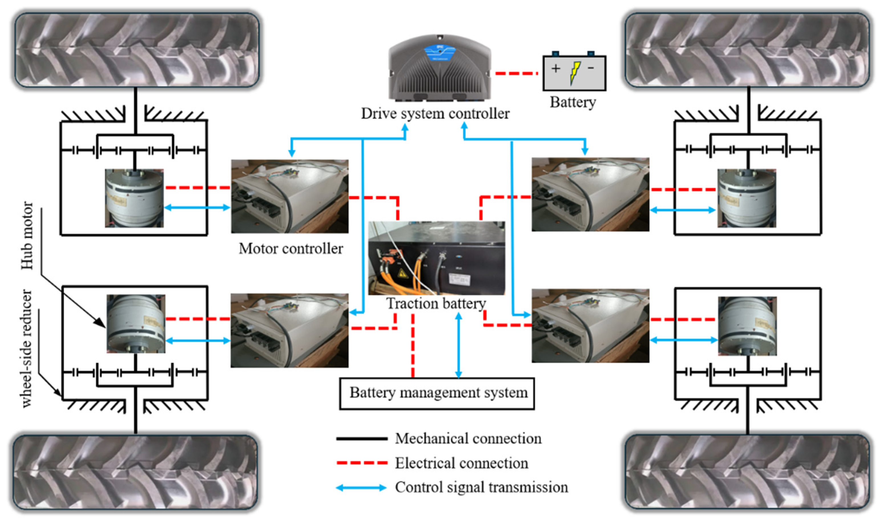
2.1.1. Structure of the Drive and Transmission System of the DDET

The research subject of this study is a four-wheel DDET powered by individual hub motors, with its drive and transmission system architecture illustrated in Figure 1.
The power output components of this DDET are hub motors. Hub motor is a drive technology where the electric motor is integrated within the vehicle’s wheel, serving as the core component of the distributed drive system. Each wheel of this DDET is independently driven by its respective hub motor. Additionally, to ensure dynamic performance during tractor operation, wheel-side reducers are installed between the hub motors and wheels as transmission components, amplifying the torque output from the hub motors before delivering it to the wheels, thereby propelling the tractor. During operation, the traction battery serves as the power source, supplying energy to each hub motor and motor controller. Simultaneously, the battery management system (BMS) monitors the battery’s voltage, current, capacity, and temperature in real time to ensure operation within safe parameters. The drive system controller, solely powered by a battery, is programmed with the tractor’s holistic drive strategy. When the driver modifies the overall power demand, the drive system controller issues control signals to each motor controller based on the predefined strategy. The motor controllers then adjust the speed of the corresponding hub motors, enabling the tractor to swiftly reach the target operational speed range as intended by the driver [15].

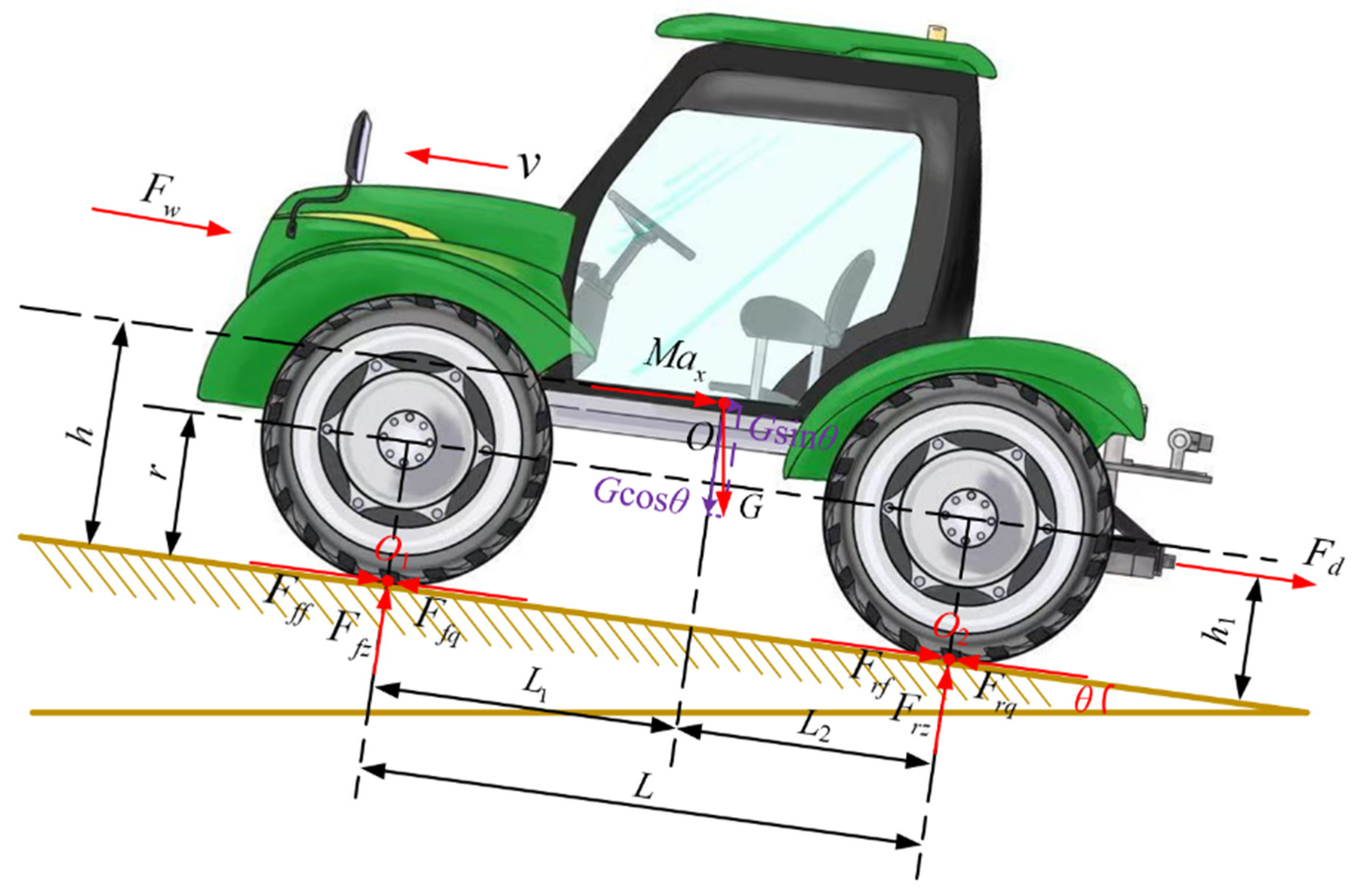
2.1.2. Dynamic Analysis of Traction Operations of Distributed Drive Electric Tractor

To determine the required drive torque of the tractor under traction operations, a dynamic analysis of the DDET in the traction direction was conducted [16]. To simplify the force analysis and facilitate subsequent research, the following assumptions were made: During tractor operation, all four wheels have identical dynamic radii, and the forces on the left and right wheels are symmetrical. In addition, during tractor operation, all four wheels experience no slip, and there is no rotational speed difference between them.
Based on these assumptions, the force analysis of the DDET during traction operations is illustrated in Figure 2.
In Figure 2, O represents the tractor’s center of mass; O1 and O2 denote the force application points of the front and rear wheels during operation, respectively; θ is the slope angle during tractor operation (deg); h is the height of the center of mass above ground (m); h1 is the ground clearance height of the traction resistance (m); r is the dynamic radius of the tractor tire (m); L is the tractor’s wheelbase (m); L1 and L2 are the distances from the center of mass to the front and rear wheel centers, respectively (m); M is the total mass of the tractor including the attached implement (kg); v is the operational speed of the tractor (m/s); G is the gravitational force acting on the tractor (N); Fff and Frf are the rolling resistances of the front and rear wheels, respectively (N); Ffz and Frz are the vertical reaction forces on the front and rear wheels, respectively (N); Ffq and Frq are the driving forces of the front and rear wheels, respectively (N); Fw is the aerodynamic resistance acting on the tractor (N); Fₐ is the acceleration resistance (N); and Fd is the traction resistance (N).
Based on the force analysis illustrated in Figure 2, the force equilibrium equations for the DDET in the traction direction can be expressed as follows:
F f q + F r q F f f F r f F d F w F a G sin θ = 0
In Equation (1), Fw and Fₐ can be specifically expressed as
F w = C D A ρ v 2 2 F a = M a x
In Equation (2), CD is the wind resistance coefficient; A represents the windward area (m2) of the tractor; ρ is the density of air (kg/m3); and ax represents tractor acceleration (m/s2). Equation (1) can be specifically expressed as:
F f q + F r q F f f F r f F d C D A ρ v 2 2 M a x G sin θ = 0
The force equilibrium equations perpendicular to the tractor’s operational direction can be expressed as
F f z + F r z G cos θ = 0
Since the exact points of application for aerodynamic resistance Fw and acceleration resistance Fa are difficult to determine during actual tractor operation, and considering that tractors typically operate at slow, constant speeds where Fw and Fa are negligible compared to traction resistance Fd, this study neglects the effects of Fw and Fa in the torque analysis of the DDET [17]. The moment equilibrium equations with O1 and O2 as the centers of rotation can be expressed as
G cos θ · L 1 G sin θ · h + F r z · L F d · h 1 = 0 G cos θ · L 2 G sin θ · h F f z · L F d · h 1 = 0
By rearranging Equation (5), the dynamic vertical loads on the rear and front wheels during tractor traction operation can be obtained as
F r z = G cos θ · L 1 + G sin θ · h + F d · h 1 L F f z = G cos θ · L 2 G sin θ · h F d · h 1 L
Based on Equation (6), the rolling resistances of the rear and front wheels (Frf and Fff) for the DDET during traction operations can be expressed as
F r f = f r · F r z F f f = f f · F f z
By combining Equations (2)–(7), the required driving force (Freq) for the tractor during traction operations can be expressed as
F r e q = F f q + F r q = f f · F f z + f r · F r z + F d + G sin θ
The required drive torque (Treq) can be further expressed as
T r e q = F r e q · r

2.2. Modeling of Drive and Transmission Components for Distributed Drive Electric Tractor

2.2.1. Modeling of Hub Motor

For the hub motor, the relationship between its output power, rotational speed, and torque can be expressed as [18]
P m = n m T m 9549
In Equation (10), Pm is the output power of the motor (kW); nm is the rotational speed of the motor (r∙min−1); and Tm represents the output torque of the motor (N∙m).
The electrical power consumed by hub motor, that is, its input power, can be expressed as [18]
P i n = U i n I i n 1000
In Equation (11), Pin is the input power of the motor (kW); Uin is the input voltage of the motor (V); and Iin is the input current of the motor (A). Both can be measured through current and voltage sensors. The efficiency values of the hub motor at different operating points can be expressed as
η m = P m P i n = n m T m 9.549 U i n I i n
For the DDET, the hub motor serves as the sole driving component. The operational efficiency of hub motors largely determines the total energy consumption of the system. Therefore, establishing a high-precision hub motor model is particularly crucial for addressing energy efficiency challenges in the DDET. In this study, a hub motor test bench is employed to conduct speed–torque–efficiency characteristic tests. By applying control signals of varying intensities and collecting operating points under different loads, the motor’s performance is evaluated. The speed–torque–efficiency MAP of an electric motor is a graphical representation of the relationship between motor efficiency, rotational speed, and torque, which visually demonstrates the distribution of efficiency performance across the entire operating range of the motor. Based on the obtained experimental data, this study employed numerical interpolation to derive the speed–torque–efficiency MAP of the hub motor.
The specifications of the hub motor used in this study are presented in Table 1. The structure of the in-wheel motor test bench is shown in Figure 3, where the hub motor, torque–speed sensor, and magnetic powder brake are connected via couplings, with power supplied by the traction battery. The test bench measurement and control system primarily employed 0–5 V analog signals to control the magnetic powder brake for simulating various motor load conditions. Motor speed regulation was achieved through 0.8–3.4 V analog control signals. Data acquisition during testing was performed by the test bench control cabinet using an NI-USB6363 data acquisition card.
During the speed–torque–efficiency characteristic testing of the hub motor in this study, the motor control signal was initially set to 0.8 V. After the rotational speed stabilized, loading was applied to the motor by adjusting the magnetic powder brake control signal in 0.1 V increments. When the motor ceased rotation due to excessive load, loading was halted, and the motor control signal was increased by 0.1 V. Once the motor speed stabilized, the aforementioned loading procedure was repeated until the loading test under a 3.4 V control signal was completed.
Based on these tests, a hub motor speed–torque–efficiency MAP is generated using numerical interpolation, as shown in Figure 4. As shown in Figure 4, when the hub motor operates within the range where the rotational speed exceeds 200 r∙min−1 and the torque exceeds 30 N∙m, its efficiency is mostly above 0.65, indicating a relatively high efficiency level. Within this range, as the motor’s speed and torque increase, the efficiency also rises, reaching a peak value of 0.87. However, when the motor operates near its maximum torque or maximum speed, the efficiency declines significantly. For instance, when the rotational speed exceeds 800 r∙min−1 or the torque exceeds 90 N∙m, the motor efficiency gradually decreases.

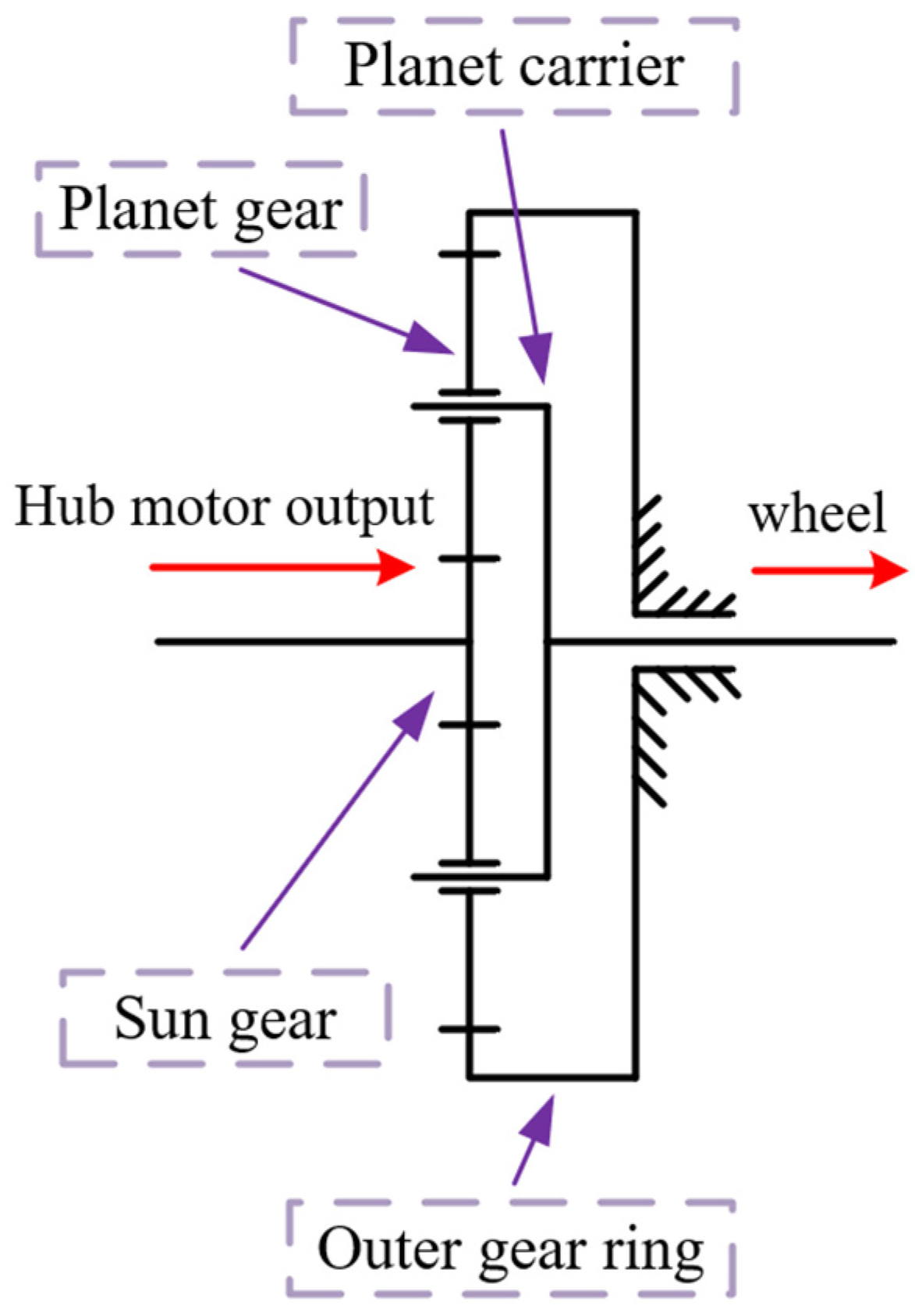
2.2.2. Modeling of Wheel-Side Reducer

To achieve the objective of increasing the output torque of the hub motor, the wheel-side reducer in this study adopts the transmission configuration illustrated in Figure 5. The output shaft of the hub motor is connected to the sun gear of the planetary gear set as the input, where the sun gear meshes with the planet gears. With the outer gear ring fixed, the planet carrier serves as the output component connected to the wheel, thereby completing the power transmission from the hub motor to the wheel.
Under this transmission configuration, the numerical relationship between the wheel speed and the hub motor output speed can be expressed as [18]
ω w = ω m i g
In Equation (13), ωw is the rotational speed of the wheel (r∙min−1); ωm is the rotational speed of the hub motor (r∙min−1); and ig is the transmission ratio of the wheel-side reducer.
The numerical relationship between the wheel torque and the output torque of the hub motor can be expressed as [18]
T w = T m · i g
In Equation (14), Tw is the torque of the wheel (N∙m); Tm is the output torque of the hub motor (N∙m).

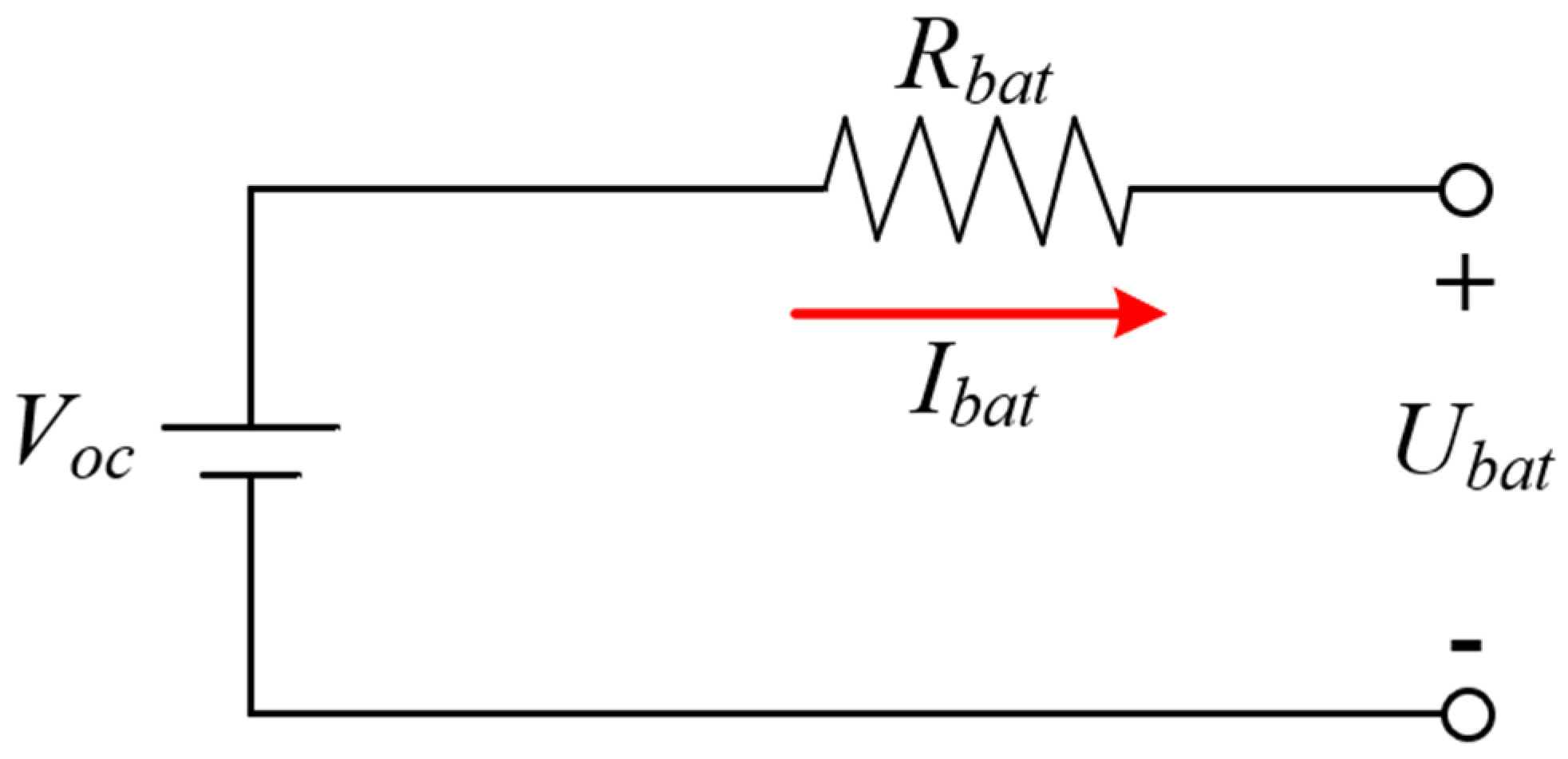
2.2.3. Modeling of Traction Battery

To quantitatively evaluate the power consumption of the traction battery, this study employs an equivalent internal resistance model to describe the State of Charge (SOC) variation process. The equivalent internal resistance model is illustrated in Figure 6.
As shown in the electrical relationship in Figure 6, the terminal voltage of the traction battery can be expressed as
U b a t = V o c I b a t R b a t
In Equation (15), Ubat is the terminal voltage of the traction battery (V); Voc is the open-circuit voltage of the traction battery (V); Ibat is the traction battery bus current (A); and Rbat is the internal resistance of the traction battery (Ω).
Ibat can be specifically expressed as [19]
I b a t = V o c V o c 2 4000 R b a t P b a t 2 R b a t
In Equation (16), Pbat is the output power of the traction battery (kW).
The ampere-hour (Ah) integration method is a technique for calculating the charge/discharge capacity of a battery by integrating current over time. In the field of electric vehicles, it is commonly used for real-time estimation of the SOC in traction batteries. Based on the Ah integration method, the dynamic variation of the traction battery’s SOC under operating conditions is expressed as
S O C ( k + 1 ) = S O C ( k ) k k + 1 I b a t ( k ) d t 3600 Q b a t
In Equation (17), Qbat is the capacity of the traction battery (A∙h). In this study, the battery capacity was taken as 100 A∙h.

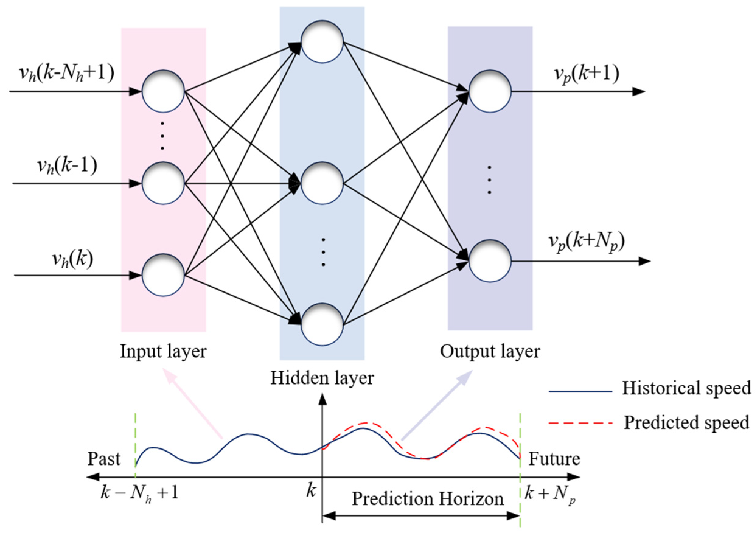
2.3. Tractor Operational Speed Prediction Model Based on Backpropagation Neural Network

2.3.1. Design of Backpropagation Neural Network

For the distributed drive electric tractor, considering only the current operational speed will lead to hysteresis in energy-efficient control, making real-time energy efficiency optimization difficult. Therefore, rapid and accurate prediction of operational speed enables the advanced acquisition of the tractor’s speed conditions in the next prediction horizon, ensuring indirect derivation of hub motor speed information over a future finite time domain. Consequently, this study employs a backpropagation (BP) neural network to establish the tractor speed prediction model. The BP neural network is an artificial neural network capable of constructing precise mapping relationships between inputs and outputs while enabling rapid information processing in complex systems. It is widely applied in nonlinear time-series prediction [20]. In this study, the input layer of the BP neural network receives historical operational speed sequence values, the hidden layer characterizes the nonlinear relationship between input and output sequences, and the output layer generates the predicted speed sequence for the target horizon. Thus, the input–output relationship of the tractor operational speed prediction model can be expressed as
[ v p ( k + 1 ) , v p ( k + 2 ) , , v p ( k + N p ) ] = f B P [ v h ( k N h + 1 ) , , v h ( k 1 ) , v h ( k ) ]
In Equation (18), vp is the predicted operational speed sequence; vh is the historical operational speed sequence; k is the current time step; Np is the prediction horizon length; Nh is the length of the historical operational speed sequence; and fBP represents the internal mapping relationship of the BP neural network. Based on the above analysis, the principle of BP neural network operational speed prediction is illustrated as shown in Figure 7.
In this study, the training of the BP neural network employs the gradient descent method to enable rapid adjustment of neuron weights and thresholds. Since tractor operational speed prediction constitutes a typical nonlinear problem, it is necessary to introduce activation functions in the BP neural network to endow it with the capability to learn and represent nonlinear functions, thereby achieving fitting for various types of curves. The tan-sigmoid function is selected as the activation function for the BP neural network, whose mathematical expression is given as
f ( x ) = e x e x e x + e x
In this study, the number of nodes in the input layer and output layer of the BP neural network is consistent with the prediction horizon length, while the number of hidden layer nodes is a critical parameter determining prediction performance. Through exhaustive iterative testing, the optimal number of hidden layer nodes was determined to be 5, at which point the prediction accuracy reaches its peak.
Finally, to validate the prediction accuracy of the proposed model for tractor operational speed within the finite time horizon, the root mean square error (RMSE) is selected as the evaluation metric, whose calculation method can be expressed as
R p = i = 1 N p [ v p ( k + i ) v r ( k + i ) ] 2 N p RMSE = k = 1 N R p 2 N
In Equation (20), vr is the actual operating speed of the tractor (km/h); N is the total sampling duration (s) for the complete working conditions. For the operational speed prediction problem, a smaller RMSE value indicates that the predicted operational speed output by the model is closer to the actual operational speed at corresponding time points, demonstrating better prediction performance of the model throughout complete working conditions.

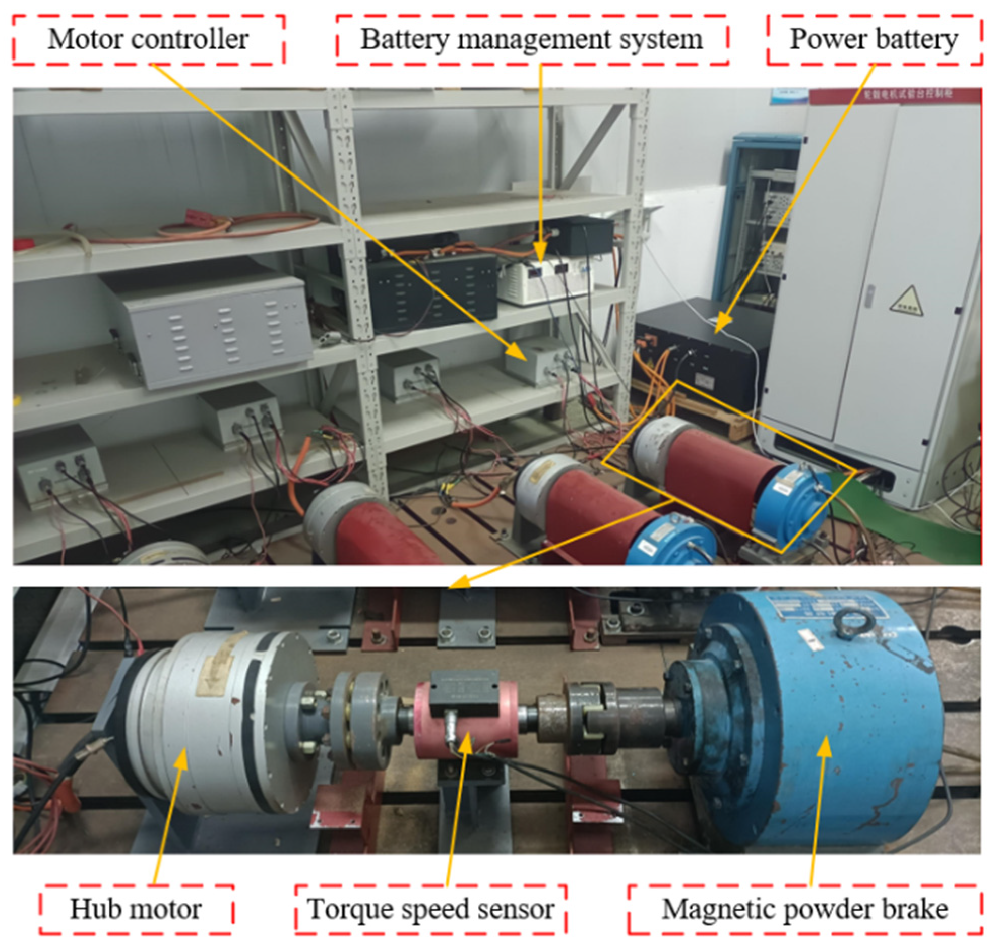
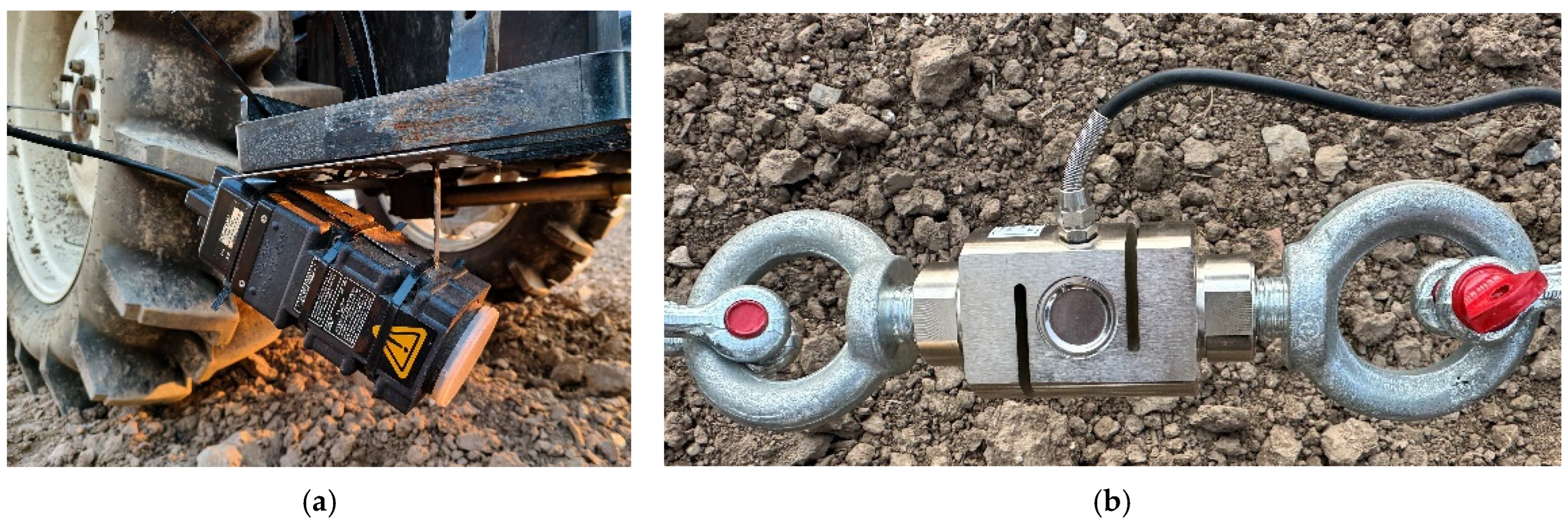
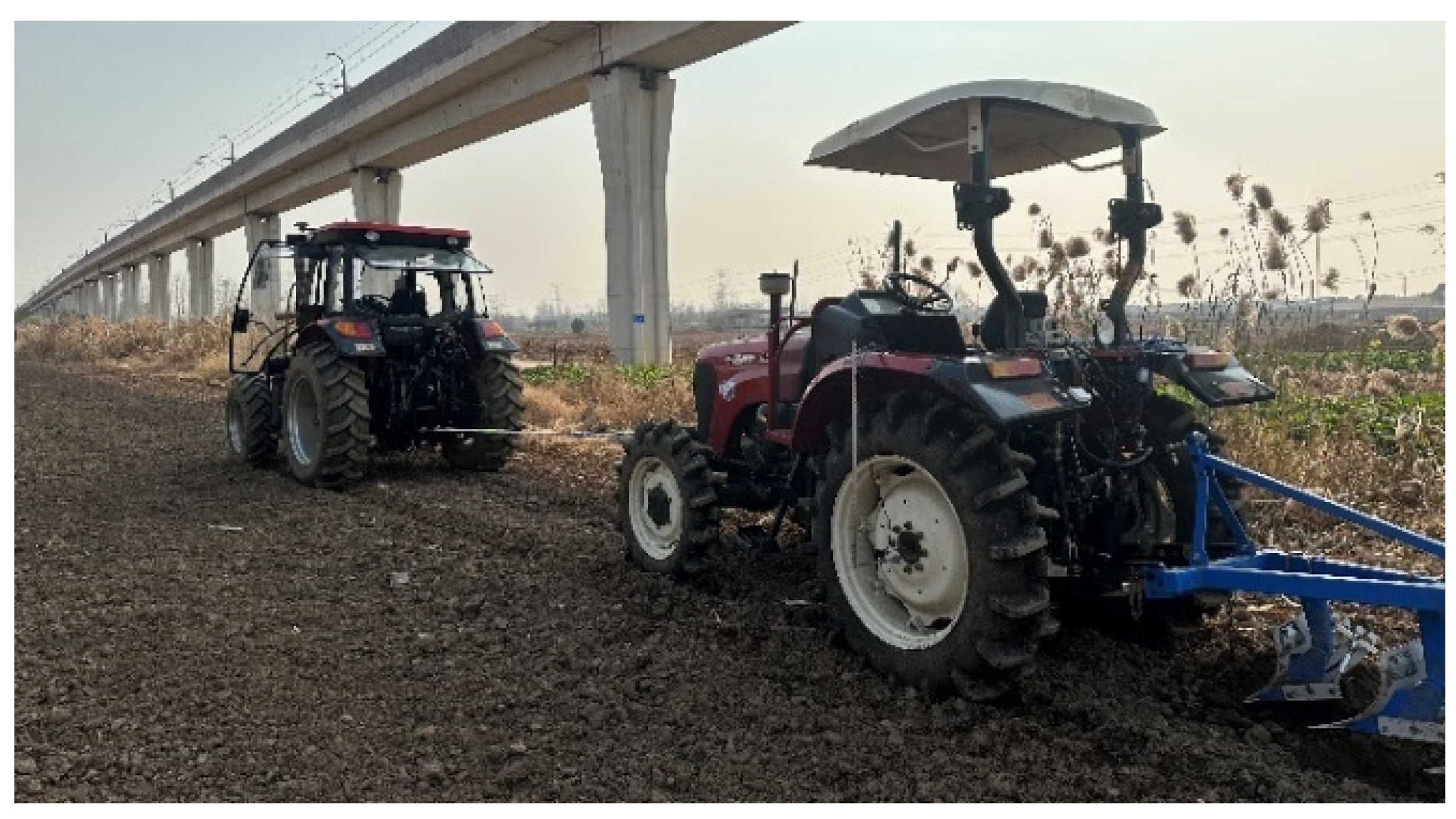
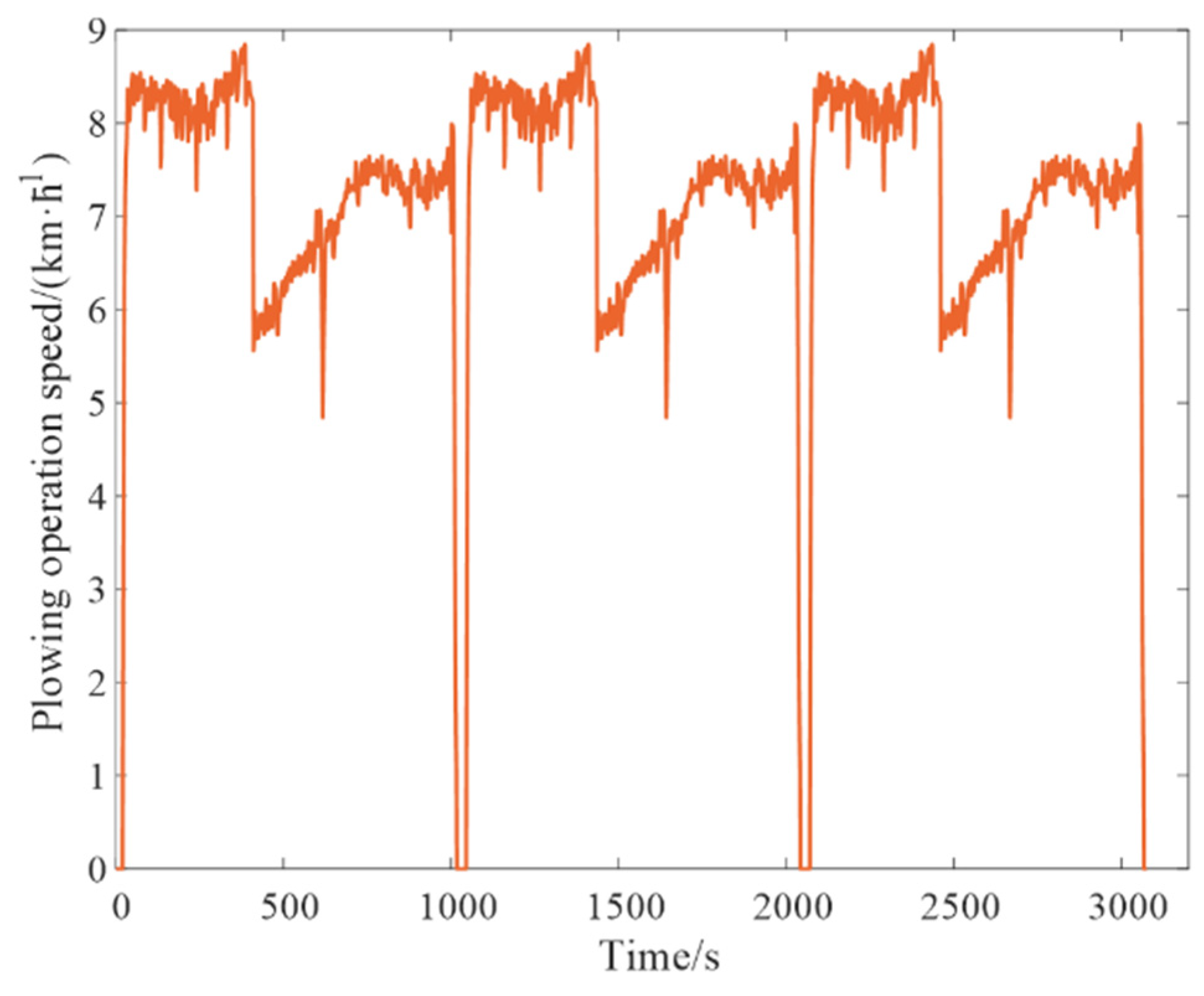
2.3.2. Tractor Plowing Operation Speed Acquisition Experiment

To enhance the authenticity and reliability of the prediction results from the established tractor speed prediction model, actual operational speed data must be utilized for model training. This study employs the plowing operation as a representative working condition, collecting real-time speed data during tractor plowing operations to construct a cyclic training dataset [21]. During the experimental preparation phase, a Doppler radar speed sensor was mounted on the test tractor with a fixed installation angle. The actual operating speed of the tractor was derived by calculating the Doppler frequency shift. Simultaneously, a tension–compression force sensor was connected to the auxiliary tractor via a tow rope. The signal feedback from this sensor provided the travel resistance exerted on the test tractor during operation. The installation positions of both sensors are illustrated in Figure 8. Based on the feedback from the Doppler radar speed sensor and the tension–compression force sensor, data on the operating speed and travel resistance during tractor plowing were acquired. These measurements were used to construct a cyclic training dataset for operational speed. Furthermore, the plowing performance of the tractor was evaluated from both kinematic and dynamic perspectives, establishing experimental references for subsequent plowing condition modeling.
During this experiment, the test tractor was first placed in neutral gear with the plow body lowered to a specified tillage depth. An auxiliary tractor then towed the test tractor at varying travel speeds to simulate actual plowing operations. The operational speed and travel resistance of the test tractor were measured using a Doppler radar speed sensor and a tension–compression force sensor, thereby completing the data acquisition of tractor plowing speed. The experimental setup is illustrated in Figure 9.
Based on the aforementioned experimental results, the tractor operational speed cycle training dataset for this study is established as shown in Figure 10. The training dataset has a length of 3075 samples, consisting of three identical operational speed conditions. Each individual operational speed training data segment includes the complete working process from tractor startup to high-speed stable plowing, rapid deceleration, followed by gradual acceleration, and low-speed stable plowing operations. This dataset demonstrates strong representativeness of speed characteristics for tractor plowing operations.

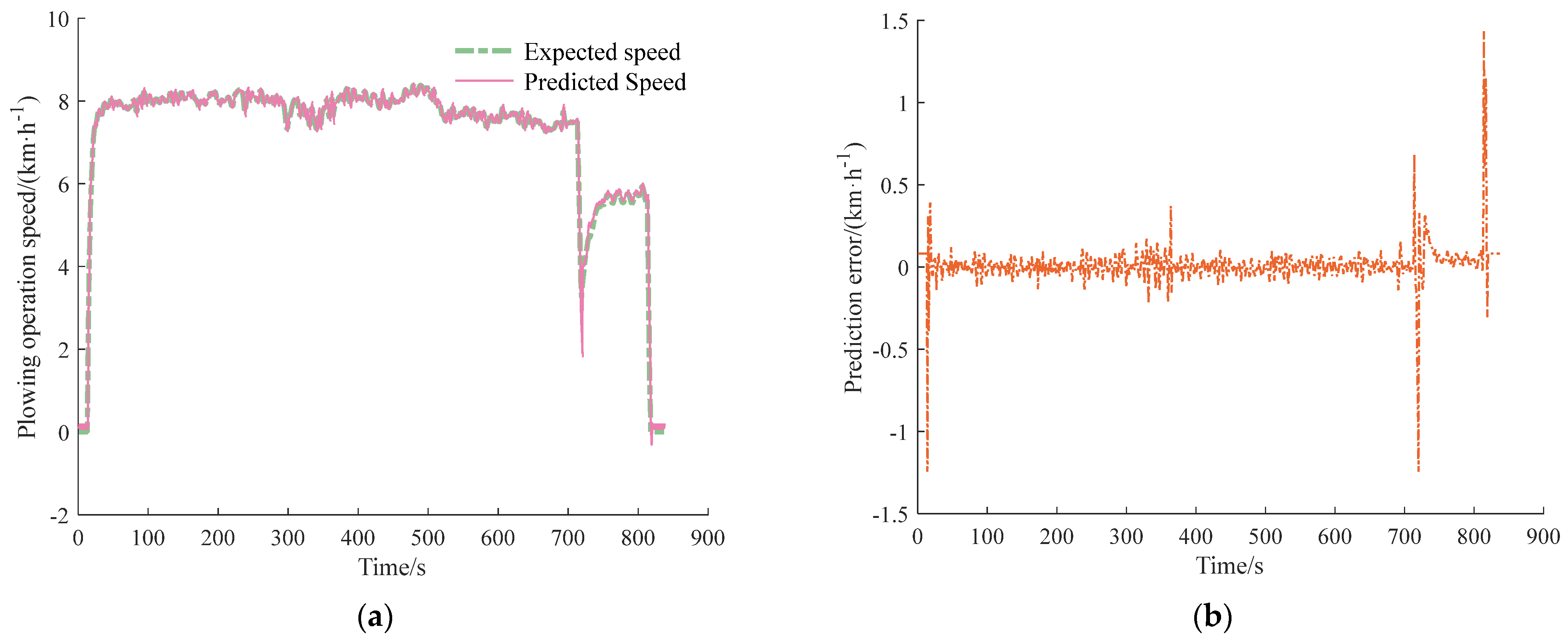
2.3.3. Prediction Results and Analysis of Tractor Operational Speed

Based on the established backpropagation neural network prediction model, operational speed prediction under different prediction horizons was conducted for the tractor plowing operation. Regarding the selection of prediction horizon length, for passenger vehicles, speed fluctuations during normal driving are minimal with rare instances of sudden acceleration/deceleration, making 5 s, 10 s, or even 20 s prediction horizons typical for long-term speed prediction. In contrast, tractor plowing speed exhibits fluctuations due to factors like soil hardness and tillage depth. For instance, encountering compacted soil may cause abrupt deceleration, adversely affecting prediction accuracy. Thus, long-horizon speed prediction is unsuitable for tractors. Through comparative analysis, this study selects 2 s, 5 s, and 8 s prediction horizons for tractor plowing speed prediction. The test condition was derived from the operational speed acquisition experiments described in Section 2.3.2, with prediction results across different horizons illustrated in Figure 11, Figure 12 and Figure 13.
Based on the image data, the RSME in different prediction horizons is calculated based on Equation (20), and the collation results are shown in Table 2.
Analysis of Figure 11, Figure 12 and Figure 13 reveals that certain errors exist between the predicted operational speed results and the test conditions across different prediction horizons. The maximum errors primarily occur during periods of abrupt tractor speed variation. For prediction horizons of Np = 2 s and Np = 5 s, the predicted trends generally align with the test condition, whereas at Np = 8 s, significant deviations emerge after 715 s. As shown in Table 2, among the three prediction horizons evaluated, Np = 2 s yields the smallest RMSE value, indicating the closest agreement between prediction and test condition and thus the highest prediction accuracy. As Np increases, the RMSE values also rise: The increments are 0.1092 (from Np = 2 s to 5 s) and 0.1716 (from Np = 5 s to 8 s), demonstrating that longer prediction horizons lead to reduced prediction accuracy.
However, although Np = 2 s yields optimal speed prediction performance, an excessively short prediction horizon implies that the tractor’s drive system response would vary too rapidly with time. This may prevent the control system from adequately predicting and adapting to future system variations, thereby degrading control performance [22]. Conversely, Np = 8 s demonstrates unsatisfactory prediction accuracy and fails to achieve precise predictions over longer time horizons. Therefore, after comprehensive consideration of prediction horizon characteristics, prediction errors, RMSE increments, and other factors, this study adopts Np = 5 s for subsequent research.

2.4. Design of Real-Time Energy-Efficient Control Strategy Based on Model Predictive Control

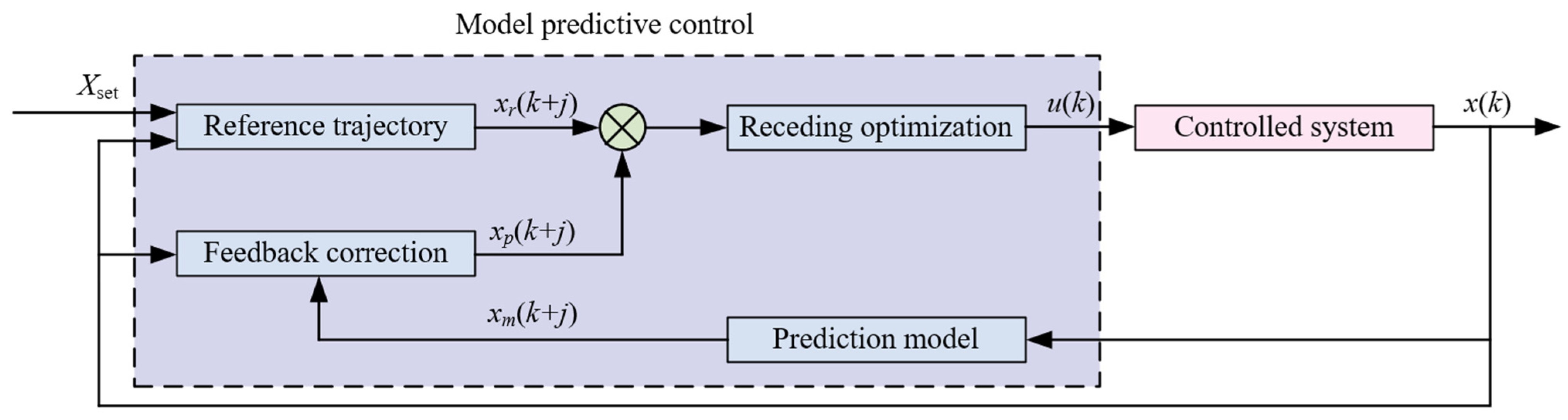
2.4.1. Principles of Model Predictive Control

Model predictive control (MPC) is a control algorithm based on a predictive model that solves the optimal control problem for the controlled system over a finite time horizon at each sampling instant. The MPC system structure primarily consists of a prediction model, receding optimization, feedback correction, and reference trajectory, as illustrated in Figure 14.
Combining the MPC system structure shown in Figure 14 and the research objectives of this study, the tractor operational speed prediction model established in Section 2.3 serves as the predictive model for this study, while the DDET acts as the controlled system. The predictive model forecasts the DDET’s operational speed information over a finite future horizon. An appropriate solving algorithm is then employed to resolve the energy-efficient control problem within this prediction horizon, yielding an optimal control sequence. The first control input from this sequence is applied to the DDET, and the same method is rolled forward iteratively until the operation’s completion. During this process, upon completing the computation for each prediction horizon, the actual state values of the DDET are fed back to the control unit at the next time step, enabling online feedback correction. Additionally, to prevent abrupt system state variations and excessive energy consumption, a reference trajectory for the SOC of the traction battery must be predefined in accordance with the energy consumption dynamics of the DDET during the solving process [23].

2.4.2. Establishment of a Real-Time Energy-Efficient Control Strategy Framework

This study takes the DDET as the controlled system. Essentially, the energy-efficient control of DDET can be formulated as a torque distribution problem among hub motors. The key to achieving whole-machine energy efficiency lies in optimal torque allocation to keep hub motors operating in their high-efficiency zones [24,25]. The controlled system is represented by the following discrete dynamic system:
x ( k + 1 ) = f [ x ( k ) , u ( k ) ]
In Equation (21), x(k) is the system state variable, and u(k) is the system control variable.
From Equation (6) and practical farming experience, it is known that during traction operations of a DDET, the presence of traction resistance leads to increased vertical load on the rear wheels, necessitating greater drive torque from the rear-wheel motors. Therefore, this study designates the rear-wheel motor as the primary drive motor, while the front-wheel motor serves as an auxiliary unit to ensure overall operational power performance. Consequently, the drive torque of the rear-wheel motor (Trq) is selected as the system control variable:
u ( k ) = [ T r q ( k ) ]
To meet the dynamic performance requirements of the rear-wheel motor, dynamic range constraints are applied:
T r e q ( k ) 2 T r q ( k ) T r e q ( k )
In Equation (23), Treq is the driving torque of the whole machine (N∙m).
Based on the drive–transmission relationship of the DDET, the required driving torque of each hub motor at time can be derived from the control variable as follows:
T r r ( k ) = T r l ( k ) = T r q ( k ) 2 i g η g e a r T f r ( k ) = T f l ( k ) = T r e q ( k ) T r q ( k ) 2 i g η g e a r
In Equation (24), Trr and Trl are the driving torque (N·m) of the right-rear and left-rear wheel motors, respectively; Tfr and Tfl are the driving torque (N·m) of the right-front and left-front wheel motors, respectively; and ηgear is the transmission efficiency of the wheel-side reducer.
Considering the actual operation process of the DDET, the SOC of the traction battery can directly reflect the energy status of the tractor. Therefore, the battery SOC is selected as the system state variable:
x ( k ) = [ S O C ( k ) ]
Based on the SOC relationship of the traction battery, the system state transition equation at time step k is established as follows:
S O C ( k + 1 ) = S O C ( k ) V o c V o c 2 4000 R b a t P b a t 7200 R b a t Q b a t · Δ t
Based on the power relationship of the DDET system, the power of the traction battery (Pbat) in Equation (26) can be explicitly expressed as:
P b a t = T r r n m 9549 η m _ r r + T r l n m 9549 η m _ r l + T f r n m 9549 η m _ f r + T f l n m 9549 η m _ f l
In Equation (27), ηm_rr, ηm_rl, ηm_fr, and ηm_fl represent the efficiencies of the right-rear, left-rear, right-front, and left-front hub motors, respectively.
Based on Equation (27), the overall drive efficiency of the DDET (ηeff) can be expressed as
η e f f = P out P b a t × 100 % = F r e q v / 1000 P b a t × 100 %
In Equation (28), Pout is the output power (kW) of the DDET.
For the reference trajectory of the model predictive system, the upper and lower bounds of the traction battery SOC are typically predetermined in the energy management of hybrid electric vehicles [26]. The reference trajectory of the battery SOC is then defined based on the driving range:
S O C r e f ( k ) = S O C i n i t i a l D ( k ) D t o t a l ( S O C i n i t i a l S O C e n d )
In Equation (29), SOCref(k) is the reference trajectory value of SOC at time step k; SOCinitial is for setting the initial SOC value; D(k) is the mileage (km) at time step k; Dtotal is the total mileage traveled (km); and SOCend is used to set the final SOC value. Under the influence of this reference trajectory, hybrid vehicles can rationally plan the use of fuel and electricity so that the SOC value at the end time is exactly the set SOCend.
However, the hub motors equipped on the DDET in this study currently lack power generation capability, relying solely on four motors for energy consumption. Moreover, it is difficult to determine the lower bound of the SOC during operation. Therefore, the SOC reference trajectory shown in Equation (29) is not applicable to the DDET in this study. In this context, since the real-time energy-efficient control of the DDET in this study is a typical energy-depletion problem, it is necessary to ensure that the SOC remains as constant as possible at each sampling instant [27]. This concept can be expressed as
S O C ( k 1 ) S O C ( k ) ε
In Equation (30), ε can be regarded as an infinitesimal approaching zero. Based on the charge-sustaining strategy, the SOC reference trajectory of the DDET at time step k is defined as
S O C r e f ( k ) = S O C ( k 1 ) ε
During the operation of the DDET, the energy consumption cost function Jcost at time step k can be expressed as
J cos t ( k ) = K · E b a t ( k )
In Equation (32), K is the unit electricity price (CNY/kW∙h), and Ebat(k) is the energy consumption (kW∙h) at time step k. In addition to the consumption cost, it is necessary to impose constraints on the energy consumption during operation using the SOC reference trajectory, enabling online feedback correction of SOC at each sampling instant. Therefore, an SOC correction penalty function is incorporated into the energy consumption cost function, and the cost function at time step k is expressed as
L [ x ( k ) , u ( k ) ] = J cos t ( k ) + H ( k )
In Equation (33), H(k) is the SOC correction penalty function at time step k. For the entire energy-efficient control process, the optimal cost function can be expressed as
J k [ S O C ( k ) ] = min k = 1 N { K · E b a t ( k ) + ω · [ S O C ( k ) S O C r e f ( k ) ] 2 }
In Equation (34), ω is the SOC penalty coefficient.
To ensure that all components of the DDET’s drive and transmission system operate within normal parameter ranges during the receding optimization process, it is necessary to impose constraints on the variables according to the actual parameters of each component. The specific constraints are shown in Equation (32).
S O C min S O C S O C max n f _ min n f n f _ max n r _ min n r n r _ max T f _ min T f T f _ max T r _ min T r T r _ max
In Equation (35), SOCmin and SOCmax are the minimum and maximum SOC of the traction battery, respectively; nf_min, nf_max, nr_min, and nr_max are the minimum and maximum rotational speeds (r·min−1) of the front and rear hub motors, respectively; and Tf_min, Tf_max, Tr_min, and Tr_max are the minimum and maximum output torques (N·m) of the front and rear hub motors, respectively.
For solving optimization problems within the prediction horizon, the dynamic programming (DP) algorithm is commonly employed in energy management systems for new energy vehicles [28]. Its fundamental principle involves iteratively computing all possible control variables at each known operating condition point, then determining the optimal control variable for each point based on the cost function and constraints, thereby enabling the controlled system to achieve global optimization under known operating conditions. The solution process of the dynamic programming algorithm primarily consists of two steps: backward iteration and forward optimization. Starting from the last operating condition point, the algorithm recursively computes the minimum cumulative cost function value while recording the corresponding control inputs until reaching the first operating condition point. Subsequently, based on the system state transition equation, forward optimization is performed to obtain the optimal control sequence corresponding to each operating condition point.
According to the principle of the dynamic programming algorithm, its backward iteration phase requires prior knowledge of the complete operational condition, which hinders its practical implementation in real-time vehicle control. To address this limitation, this study utilizes a tractor speed prediction model to perform DP-based optimization within the predictive horizon, generating the optimal control sequence for the system in that horizon. This process is repeated at each time step, with the prediction window shifting forward along the time axis to achieve receding optimization. This approach not only overcomes the DP algorithm’s dependence on complete driving cycle information and significantly reduces computational burden but also enables real-time energy-efficient control when combined with the prediction model [29].
Building upon the previous sections of this study, the solution process for the MPC-based real-time energy-efficient control strategy of the DDET can be summarized as follows: (1) determine the prediction horizon length and predict the tractor operational speed within the prediction horizon using a BP neural network; (2) obtain the required torque within the prediction horizon through the DDET dynamics equations; (3) based on the power transmission relationships among components of the DDET, derive the optimal control sequence within the prediction horizon using dynamic programming algorithm, and apply the first control variable to the controlled system; and (4) as the time axis advances, move to the next prediction horizon and repeat steps (1)–(3) to achieve receding optimization. This process is illustrated in Figure 15.

3. Results and Discussion

3.1. Establishment of Plowing Working Conditions

For the tractor speed conditions during plowing operation, this study adopts the test condition collected in the experimental trial described in Section 2.3.3 with Np = 5 s for operational speed forecasting. As for plowing resistance, it is commonly calculated using the empirical formula given in Equation (36):
F D = z · b · h 0 · k 0
In Equation (36), z is the number of plowshares; b is the bottom width of each plowshare (m); h0 is the tillage depth (m); and k0 is the soil-specific resistance (N·m−2). However, in actual field tests, the magnitude of plowing resistance is highly variable, and the real-time measured resistance at each sampling point cannot fully represent the resistance characteristics within the prediction horizon. Therefore, this study incorporates the actual operational load range of distributed tractors and establishes a plowing resistance model based on a sinusoidal curve to characterize the temporal variation of plowing resistance [30,31], which can be expressed as
F d = F D + 0.5 F D γ sin ( f d · k )
In Equation (37), γ is the soil heterogeneity ratio; fd is the frequency of plowing resistance variation; and k is the tractor operation time (s). Assuming the tractor experiences no plowing resistance when stationary, the plowing resistance working conditions in this study are established by combining Equations (36) and (37), as illustrated in Figure 16.

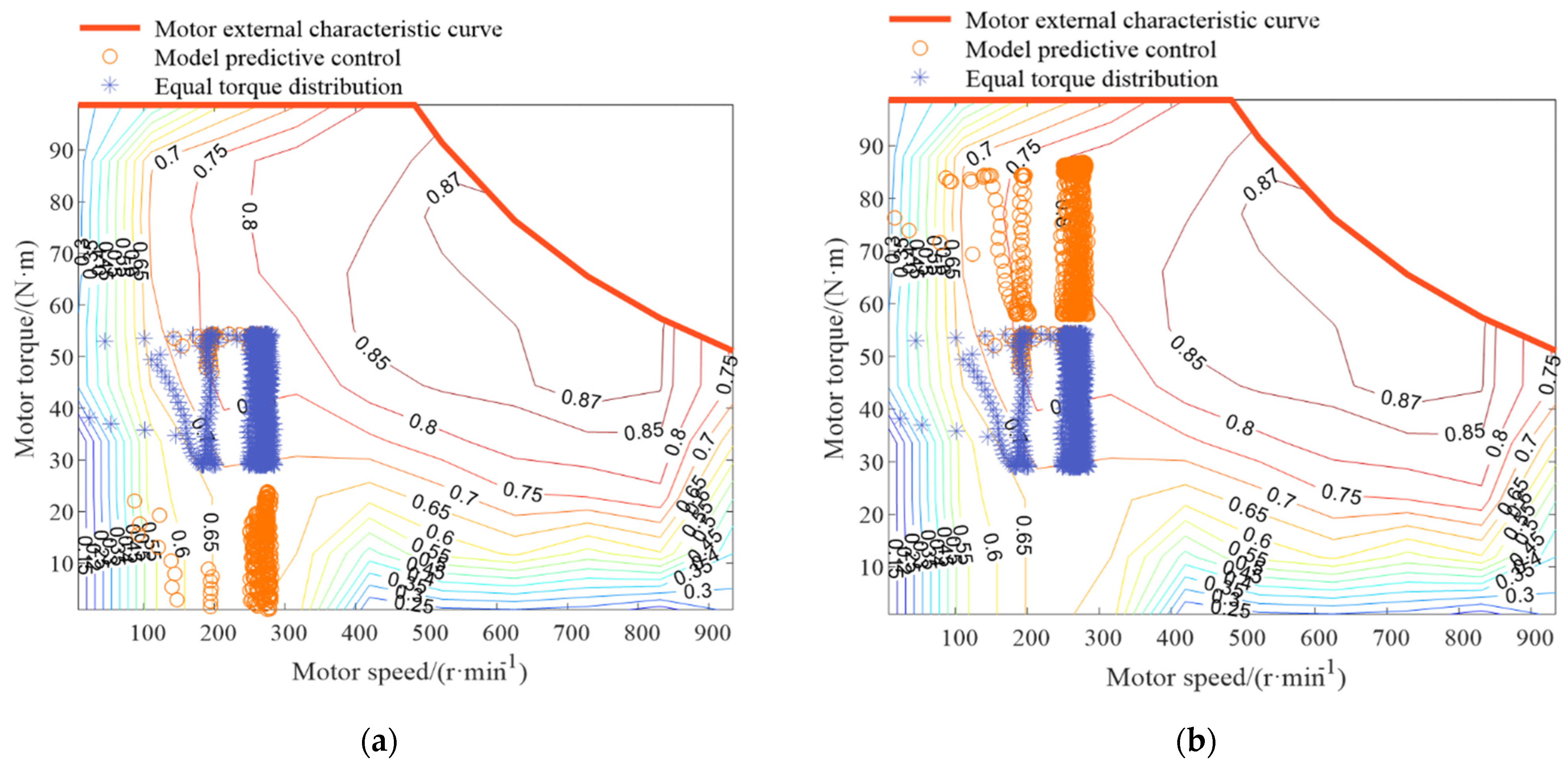
3.2. Simulation Results and Discussion

To comparatively validate the effectiveness of the MPC-based real-time energy-efficient control strategy for the DDET, this study also adopts a front/rear wheel torque equal distribution strategy. Based on the MATLAB R2022a simulation platform, both strategies were tested under identical working conditions. The comparison of motor operating points under the two strategies is shown in Figure 17, while the comparative results of traction battery power, overall drive efficiency, total energy consumption, and traction battery SOC are presented in Figure 18a–d, respectively.
Analysis of Figure 17 reveals that, by comparing the motor operating points under the two strategies, the MPC-based real-time energy-efficient control strategy successfully achieves the goal of rear-wheel motors primary drive and front-wheel motors auxiliary drive. Specifically, 57.5% of the rear-wheel motors’ operating points fall within the motor efficiency above the 0.8 range, and 93.2% of the front-wheel motors’ operating points lie in the motor efficiency above the 0.65 range. In contrast, under the equal distribution strategy, the rear-wheel motors exhibit no operating points in the efficiency range above 0.8. Thus, the MPC-based strategy significantly improves the overall efficiency of the rear-wheel motors, while the front-wheel motors’ efficiency slightly decreases compared to the equal distribution strategy. This indicates that although the MPC-based real-time energy-efficient control strategy sacrifices some front-wheel motors efficiency, it better meets the higher power demand of the rear-wheel motors while ensuring operation in a higher efficiency range. Consequently, the energy-efficient potential of the DDET is enhanced.
Analysis of Figure 18a reveals that, under plowing conditions, the MPC-based real-time energy-efficient control strategy achieves an average power of the traction battery at 5.612 kW, compared to 5.934 kW under the equal distribution strategy. This indicates that the MPC-based strategy reduces the motors’ demand on the traction battery, resulting in a 5.43% decrease in average battery power.
Analysis of Figure 18b reveals that, under the plowing condition, the MPC-based real-time energy-efficient control strategy achieves superior overall drive efficiency. The average efficiency reaches 76.02%, compared to only 71.34% with the equal distribution strategy. This represents a 6.56% improvement in average overall drive efficiency over the baseline equal distribution strategy.
Analysis of Figure 18c,d reveals that, under the plowing condition, the total energy consumption of the DDET with the MPC-based real-time energy-efficient control strategy is 1.253 kW∙h, compared to 1.325 kW∙h under the equal distribution strategy. This indicates that the MPC-based strategy consumes less energy under identical operational conditions, effectively achieving energy-efficient objectives, with a 5.43% reduction in total energy consumption compared to the equal distribution strategy. Furthermore, under the same operational conditions and an initial battery SOC of 0.7, the final SOC of the traction battery with the MPC-based real-time energy-efficient control strategy is 0.6420, whereas it is 0.6386 with the equal distribution strategy, further validating the effectiveness of the MPC-based control strategy.
Compared with Reference [14], this study not only considers the rearward shift of vertical load during tractor operation but also implements energy-efficient control, achieving a more rational drive torque distribution while significantly reducing the energy consumption of the DDET under plowing conditions. Compared with the 4.84% energy-efficient effect achieved in Reference [32] under plowing conditions, this study attains a 5.43% reduction in energy consumption within a shorter operational condition. Furthermore, compared with Reference [28], which proposed an energy management strategy for hybrid tractors using dynamic programming under fully known operating conditions, this study employs an operational speed prediction model to enable DP-based optimization within each predictive horizon, performing rolling calculations during operation to realize real-time energy-efficient control. This approach also eliminates the limitation of DP being confined to optimization under complete operating conditions.
However, the proposed energy-efficient control strategy still has room for improvement. Due to hardware and sensor limitations, only the tractor’s operational speed was collected as training input for the prediction model during the plowing operation experiment. Future studies could incorporate additional variables, such as yaw rate and pitch rate during operation, as joint inputs to the speed prediction model to further enhance prediction accuracy.

4. Conclusions

This study focuses on a distributed drive electric tractor as the research subject. A dynamic analysis of the tractor’s traction operation was conducted, and models for the hub motor, wheel-side reducer, and traction battery were developed. A BP neural network was employed to predict the tractor’s operational speed within a finite time horizon. Additionally, an MPC-based real-time energy-efficient control strategy for the DDET was proposed and compared with an equal torque distribution strategy through simulation under plowing conditions. The following conclusions were drawn:
(1) Analyzed the structure of the drive and transmission system in a DDET. Through dynamic analysis under traction operation conditions, the required torque dynamic equation was derived. By conducting a hub motor speed–torque–efficiency characteristic test, the tractor’s hub motor model was established. Additionally, an equivalent internal resistance model was employed to construct the traction battery model.
(2) Through field tests collecting tractor plowing speed data, a cyclic training dataset is established. A BP neural network-based tractor operational speed prediction model is proposed, achieving effective speed prediction within a finite time horizon.
(3) A real-time energy-efficient control strategy framework is established, comprising the controlled system design, SOC reference trajectory, optimal cost function, and constraint conditions. The dynamic programming algorithm is employed to solve the optimal cost problem in each predictive horizon through receding optimization. Consequently, an MPC-based real-time energy-efficient control strategy for the DDET is proposed.
(4) Comparative simulation experiment with the equal torque distribution strategy under plowing conditions demonstrates that the MPC-based real-time energy-efficient control strategy allocates the total drive torque more effectively according to dynamic performance requirements. The improved operating efficiency of the rear hub motors enhances the overall energy-efficient potential. Specifically, the average overall drive efficiency under the MPC-based strategy reaches 76.02%, representing a 6.56% improvement over the equal distribution strategy. The average power demand from the traction battery is 5.612 kW under the MPC-based strategy, showing a 5.43% reduction compared to the equal distribution strategy. The total energy consumption during the plowing operation is 1.253 kW·h with the MPC-based strategy, achieving a 5.43% reduction relative to the equal distribution strategy.
In summary, the MPC-based real-time energy-efficient control strategy exhibits superior performance across all evaluation metrics, achieving effective energy-efficient control for the DDET. This study provides a valuable reference for subsequent research on energy-efficient control strategies for distributed drive electric tractors. Furthermore, the successful implementation of energy-efficient control for DDET signifies substantial reductions in farming costs for farmers, effectively enhancing agricultural productivity and enabling higher economic benefits for agricultural practitioners. From a societal perspective, further energy conservation and emission reductions can achieve a win–win scenario for both natural ecosystems and farmers.

Author Contributions

Methodology, X.D., Z.W., and Z.L.; software, Z.W., K.Z., X.S., and X.H.; validation, X.D., Z.W., Z.L., K.Z., and X.S.; investigation, X.D., Z.W., and X.H.; resources, X.D. and Z.L.; writing—original draft preparation, X.D., Z.W., and X.H.; writing—review and editing, X.D. and Z.W.; supervision, Z.L.; and project administration, X.D. and Z.L. All authors have read and agreed to the published version of the manuscript.

Funding

This research was funded by the Jiangsu Agriculture Science and Technology Innovation Fund (CX(24)3028) and the Open Project of the State Key Laboratory of Intelligent Agricultural Power Equipment (SKLIAPE2025005).

Institutional Review Board Statement

Not applicable.

Data Availability Statement

The data presented in this study are available on request from the corresponding author.

Acknowledgments

We thank the anonymous reviewers for providing critical comments and suggestions that improved this manuscript.

Conflicts of Interest

The authors declare no conflicts of interest.

References

  1. Xie, B.; Wu, Z.B.; Mao, E.R. Development and Prospect of Key Technologies on Agricultural Tractor. Trans. Chin. Soc. Agric. Mach. 2018, 49, 1–17. [Google Scholar]
  2. Liu, M.N.; Lei, S.H.; Zhao, J.H.; Meng, Z.J.; Zhao, C.J.; Xu, L.Y. Review of Development Process and Research Status of Electric Tractors. Trans. Chin. Soc. Agric. Mach. 2022, 53 (Suppl. S1), 348–364. [Google Scholar]
  3. An, Y.H.; Wang, L.; Deng, X.T.; Chen, H.; Lu, Z.X.; Wang, T. Research on Differential Steering Dynamics Control of Four-Wheel Independent Drive Electric Tractor. Agriculture 2023, 13, 1758. [Google Scholar] [CrossRef]
  4. Yang, Y.P.; Shih, Y.C.; Chen, J.M. Real-time Torque Distribution Strategy for an Electric Vehicle with Multiple Traction Motors by Particle Swarm Optimization. In Proceedings of the Automatic Control Conference (CACS), 2013 CACS International, Nantou, Taiwan, 2–4 December 2013; pp. 233–238. [Google Scholar]
  5. Zhu, S.P.; Kuang, C.Y.; Chen, P.; Chen, H.P.; Wu, Z.Q. Economical Optimal Torque Distribution Control for Distributed Four-Wheel-Drive Electric Buses. Automob. Technol. 2022, 9, 15–22. [Google Scholar]
  6. Li, Q.; Li, Z.; Tang, J.M.; Wang, Y.; Zhang, B.Y.; He, D.Q. Multi-objective Torque Distribution Strategy for Distributed Drive Multi-objective Torque Distribution Strategy for Distributed Drive. Automot. Eng. 2025, 47, 489–498. [Google Scholar]
  7. Qiu, X.A. Research on Energy-saving Control Technology of Distributed Drive Pure Electric Bus. Master’s Thesis, Chongqing University, Chongqing, China, 2021. [Google Scholar]
  8. Zhang, Z.Y. Research on Optimal Torque Allocation Strategy for Distributed Drive Electric Vehicle. Master’s Thesis, Wuhan University of Science and Technology, Wuhan, China, 2019. [Google Scholar]
  9. Cheng, Y. Research on Torque Allocation Strategy Based on Energy Efficiency of Distributed Drive System. Master’s Thesis, Zhejiang University, Hangzhou, China, 2023. [Google Scholar]
  10. Lü, S.W. Research on Energy Management Strategy of Four-Wheel Drive Electric Vehicle Based on Energy Consumption Optimization. Master’s Thesis, Jilin University, Changchun, China, 2022. [Google Scholar]
  11. Xu, Y.; Jiang, L.Y.; Wei, B.; Qiu, L. An Optimal Torque Distribution Strategy for Four-Motorized-Wheel Electric Vehicle Considering Energy Conversation. IEEE Access 2020, 8, 135975–135988. [Google Scholar] [CrossRef]
  12. Dou, H.S.; Zhang, Y.T.; Fan, L.K. Design of Optimized Energy Management Strategy for All-Wheel-Drive Electric Vehicles. Appl. Sci. 2021, 11, 8218. [Google Scholar] [CrossRef]
  13. Kim, H.W.; Amarnathvarma, A.; Kim, E.; Hwang, M.H.; Kim, K.; Kim, H.; Choi, I.; Cha, H.R. A Novel Torque Matching Strategy for Dual Motor-Based All-Wheel-Driving Electric Vehicles. Energies 2022, 15, 2717. [Google Scholar] [CrossRef]
  14. Zhou, H.D.; Lu, Z.X.; Deng, X.T.; Zhang, C.; Luo, G.J.; Zhou, R.D. Study on torque distribution of traction operation of four wheel independent driven electric tractor. J. Nanjing Agric. Univ. 2018, 41, 962–970. [Google Scholar]
  15. Deng, X.T.; Sun, H.L.; Lu, Z.X.; Cheng, Z.; An, Y.H.; Chen, H. Research on Dynamic Analysis and Experimental Study of the Distributed Drive Electric Tractor. Agriculture 2023, 13, 40. [Google Scholar] [CrossRef]
  16. Li, X.Z.; Zhang, M.Z.; Liu, M.N.; Xu, L.Y.; Yan, X.H.; Lei, S.H. Optimized Design and Validation of Distributed Drive System for Electric Tractor Based on Multi-Island Genetic Algorithm. Trans. Chin. Soc. Agric. Mach. 2024, 55, 401–411. [Google Scholar]
  17. Xie, B.; Zhang, C.; Chen, S.; Mao, E.R.; Du, Y.F. Transmission Performance of Two-Wheel Drive Electric Tractor. Trans. Chin. Soc. Agric. Mach. 2015, 46, 8–13. [Google Scholar]
  18. Sun, H.L. Structural Design and Experimental Research of Distributed Drive Electric Tractor. Master’s Thesis, Nanjing Agricultural University, Nanjing, China, 2022. [Google Scholar]
  19. Zhang, K.; Lu, Z.X.; Wang, L.; Deng, X.T.; Zhang, B.; Sun, X.X. ECVT Configuration Design and Energy-Saving Control of Hybrid Tractor Based on Lever Topology Method. Trans. Chin. Soc. Agric. Mach. 2024, 55, 505–518+538. [Google Scholar]
  20. Li, S.P. Research on Driving Cycle Prediction and Energy Management Strategy Optimization of Plug-In Hybrid Electric Vehicle. Master’s Thesis, Shandong University of Technology, Zibo, China, 2023. [Google Scholar]
  21. Yang, M.; Sun, X.X.; Deng, X.T.; Lu, Z.X.; Wang, T. Extrapolation of Tractor Traction Resistance Load Spectrum and Compilation of Loading Spectrum Based on Optimal Threshold Selection Using a Genetic Algorithm. Agriculture 2023, 13, 1133. [Google Scholar] [CrossRef]
  22. Wang, S.Y. Fuel Cell Hybrid Vehicle Energy Management Strategy Based on Vehicle Speed Prediction. Master’s Thesis, Jilin University, Changchun, China, 2023. [Google Scholar]
  23. Yan, D.C. Research on Energy Management Strategy of Four-Wheel Drive PHEV Based on Multi-Source Information Fusion. Master’s Thesis, Shandong University of Technology, Zibo, China, 2022. [Google Scholar]
  24. Li, T.H.; Xie, B.; Wang, D.Q.; Zhang, S.L.; Wu, L.P. Real-time Adaptive Energy Management Strategy for Dual-Motor-Driven Electric Tractors. Trans. Chin. Soc. Agric. Mach. 2020, 51 (Suppl. S2), 530–543. [Google Scholar]
  25. Li, T.H.; Xie, B.; Li, Z.; Li, J.K. Design and Optimization of a Dual-Input Coupling Powertrain System: A Case Study for Electric Tractors. Appl. Sci. 2020, 10, 1608. [Google Scholar] [CrossRef]
  26. Zhang, B. Research on Energy Management Strategy of Hybrid Electric Vehicle Based on Speed Prediction. Master’s Thesis, Shenyang University Of Technology, Shenyang, China, 2024. [Google Scholar]
  27. Zhou, R.D.; Wang, L.; Deng, X.T.; Su, C.; Fang, S.; Lu, Z.X. Research on Energy Distribution Strategy of Tandem Hybrid Tractor Based on the Pontryagin Minimum Principle. Agriculture 2024, 14, 440. [Google Scholar] [CrossRef]
  28. Miao, H.N.; Yin, B.F.; Huang, Y.L.; Zhu, Y.H.; Xie, X.; Yun, L. Research on Power System Design and Energy Management of Series-Connected Hybrid Tractor Based on Dynamic Programming Algorithm. J. Chin. Agric. Mech. 2024, 45, 147–153. [Google Scholar]
  29. Zhu, Z.; Zeng, L.X.; Lin, Y.G.; Chen, L.; Zou, R.; Cai, Y.F. Adaptive Energy Management Strategy for Hybrid Tractors Based on Condition Prediction. J. Xi’an Jiaotong Univ. 2023, 57, 201–210. [Google Scholar]
  30. Zhang, K.; Deng, X.T.; Lu, Z.X.; Wang, T. Research on the Energy Management Strategy of a Hybrid Tractor OS-ECVT Based on a Dynamic Programming Algorithm. Agriculture 2024, 14, 1658. [Google Scholar] [CrossRef]
  31. Dou, H.S.; Wei, H.Q.; Ai, Q.; Zhang, Y.T. Control Strategy for Rotary Tillage Condition of Hybrid Electric Tractor with Coupled-split Dynamic Configuration. Trans. Chin. Soc. Agric. Mach. 2024, 55, 393–400+414. [Google Scholar]
  32. Wu, X.; Quan, L.; Zhu, X.Y.; Zhang, C. Torque Control Strategy of Electric Tractor Based on Optimal Energy Consumption. J. Agric. Mech. Res. 2025, 47, 266–272. [Google Scholar]
Figure 1. Structural schematic diagram of the drive and transmission system of the DDET.
Agriculture 15 01398 g001
Figure 2. Force analysis of traction operation of DDET.
Agriculture 15 01398 g002
Figure 3. Hub motor test bench.
Agriculture 15 01398 g003
Figure 4. Hub motor speed–torque–efficiency MAP.
Agriculture 15 01398 g004
Figure 5. Wheel-side reducer transmission mechanism schematic.
Agriculture 15 01398 g005
Figure 6. Equivalent internal resistance model.
Agriculture 15 01398 g006
Figure 7. Schematic diagram of BP neural network operational speed prediction.
Agriculture 15 01398 g007
Figure 8. Sensor installation positions. (a) Doppler radar speed sensor and (b) tension–compression force sensor.
Agriculture 15 01398 g008
Figure 9. Tractor plowing operation speed acquisition experiment.
Agriculture 15 01398 g009
Figure 10. Cyclic training dataset of plowing operation speed.
Agriculture 15 01398 g010
Figure 11. Prediction result when Np = 2 s. (a) Comparison of speeds and (b) prediction error.
Agriculture 15 01398 g011
Figure 12. Prediction result when Np = 5 s. (a) Comparison of speeds and (b) prediction error.
Agriculture 15 01398 g012
Figure 13. Prediction result when Np = 8 s. (a) Comparison of speeds and (b) prediction error.
Agriculture 15 01398 g013
Figure 14. Model predictive control system structure.
Agriculture 15 01398 g014
Figure 15. Schematic diagram of MPC-based real-time energy-efficient control strategy solution.
Agriculture 15 01398 g015
Figure 16. Plowing resistance curve.
Agriculture 15 01398 g016
Figure 17. Motor operating points comparison diagram. (a) Front-wheel motors operating points comparison and (b) rear-wheel motors operating points comparison.
Agriculture 15 01398 g017
Figure 18. Overall machine performance comparison diagram. (a) Traction battery power change curve; (b) overall drive efficiency change curve; (c) total energy consumption change curve; and (d) traction battery SOC change curve.
Agriculture 15 01398 g018
Table 1. Hub motor specifications.
Hub Motor ParametersValues
Rated voltage200 V
Rated power5 kW
Maximum output torque100 N∙m
Control signal voltage0.8~3.4 V
Table 2. Prediction result.
Prediction Horizon (s)RMSE (km∙h−1)RMSE Increment
20.1382-
50.24740.1092
80.41900.1716
Disclaimer/Publisher’s Note: The statements, opinions and data contained in all publications are solely those of the individual author(s) and contributor(s) and not of MDPI and/or the editor(s). MDPI and/or the editor(s) disclaim responsibility for any injury to people or property resulting from any ideas, methods, instructions or products referred to in the content.

