2.2.1. Adaptive Feeding Mechanism
As shown in
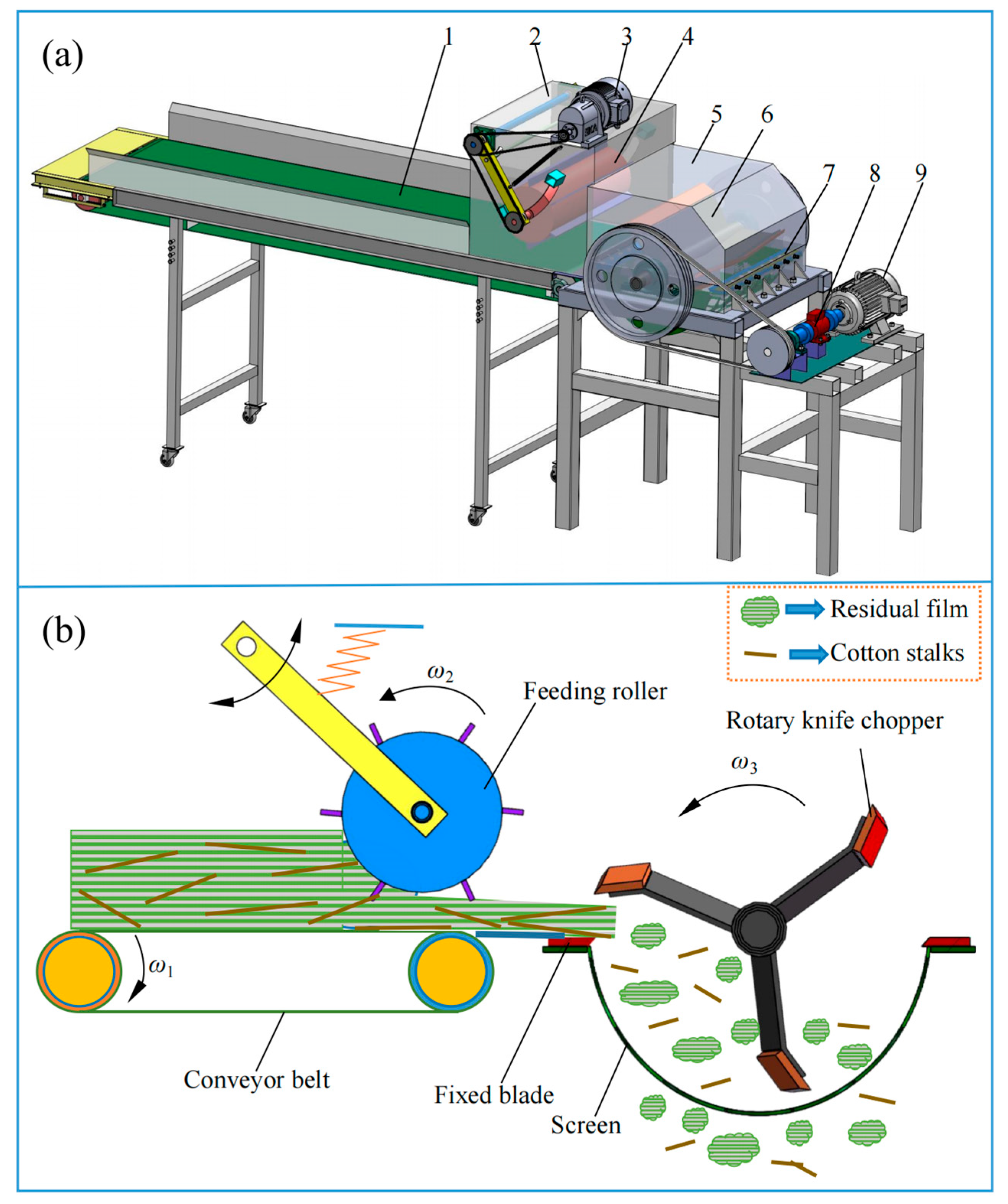
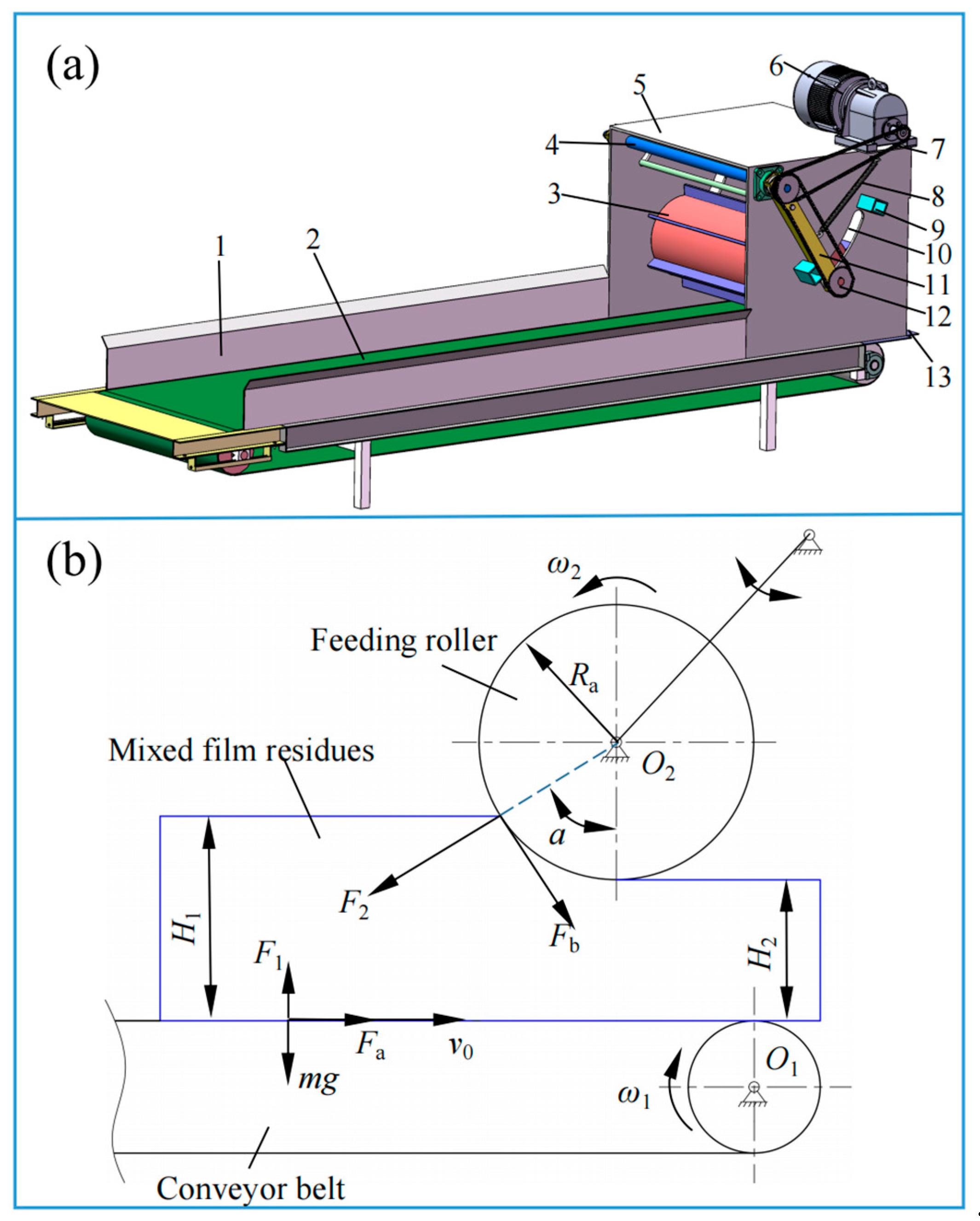
Figure 2a, the feeding mechanism consists of a feeding motor, a first chain wheel assembly, a second chain wheel assembly, a frame, and a feeding roller. The feeding motor drives the rotation of the feeding roller via the first and second chain wheel assemblies. The gap adjustment component includes a rotary shaft, a tension spring, a rotating arm, a guide slot, and a limit block. During operation, the linear rotational speed at the lower end of the feeding roller aligns with the conveyor belt’s direction of movement. As fluctuations in mixed film residues feeding volume occur, the feeding roller moves adaptively up and down along the guide slot around the rotary shaft. This enables real-time, automatic adjustment of the gap between the feeding roller and the conveyor belt, ensuring that the mixed film residues are always subjected to a specific amount of pressure.
The feeding mechanism facilitates the feeding of mixed film residues through the applied force from the feeding roller and conveyor belt. Based on the theory of stalk rupture and fracture under directional feeding conditions [
11,
12], an analysis of the forces and motion acting on the mixed film residues during the feeding process is conducted to ensure smooth feeding and prevent blockages, as shown in
Figure 2b.
As shown in
Figure 2b, the necessary condition for stable and uniform feeding of the mixed film residues is that the frictional force acting on it must be greater than or equal to the component of the normal force, as expressed by:
where
In Equations (1) and (2), F1 represents the supporting force exerted by the conveyor belt on the film-mixed residues, N; F2 represents the normal force applied by the feeding roller on the mixed film residues, N; Fa represents the static frictional force exerted by the conveyor belt on the mixed film residues, N; Fb represents the static frictional force exerted by the feeding roller on the mixed film residues, N; ɑ represents the feeding angle, in degrees (°); μa represents the coefficient of static friction between the conveyor belt and the mixed film residues; μb represents the coefficient of friction between the feeding roller and the mixed film residues; m represents the mass of the mixed film residues, kg; and g represents the acceleration due to gravity, m·s−2.
By combining Equations (1) and (2), the following result can be obtained:
Since
μamg/
F1 + (
μa +
μb) ≥ 0 holds true in Equation (3), it is sufficient for the inequality (
μa +
μb)cos
θ ≥ (1 −
μaμb)sin
ɑ to be satisfied for Equation (3) to be valid. According to the relevant literature [
13], the coefficient of static friction between the conveyor belt and the film-mixed residue (
μa) is 0.44, and the coefficient of static friction between the feeding roller and the mixed film residues (
μb) is 0.34. By solving this inequality, the feeding angle
α is found to be ≤42°. This ensures that a feeding angle
α ≤ 42° facilitates uniform and effective feeding of the mixed film residues while applying a sufficient compressive force.
The conveyor belt width, feeding roller diameter, and rotational speed are directly related to the grabbing, conveying performance, and productivity of the mixed film residues. To ensure stable feeding of the mixed film residues and meet the productivity requirements, it is necessary to appropriately set the conveyor belt width, feeding roller diameter, and rotational speed. As shown in
Figure 2b, the following occurs:
In Equation (4),
Q represents the productivity, kg/h;
η represents the material fill coefficient, set at 0.2 [
14];
va represents the feeding speed, m/s;
κa represents the bulk density of the mixed film residues, t/m
3;
B represents the conveyor belt width, mm;
H1 represents the height of the mixed film residues before feeding, mm;
H2 represents the height of the mixed film residues after feeding, mm;
Ra represents the radius of the feeding roller, mm; and
na represents the rotational speed of the feeding roller, r/min.
Assuming that the mixed film residues’ height before feeding (
H1) is 230 mm and after feeding (
H2) is 80 mm, the radius of the feeding roller (
Ra) is calculated to be 200 mm, with a length of 800 mm, based on Equation (4). To improve the feeding roller’s grip and reduce the risk of residual film entangling the shaft, rectangular pressing plates are evenly installed along its circumference. The conveyor belt width (
B) is set to 800 mm, matching the length of the feeding roller, with the total conveyor belt length set to 3000 mm. The conveyor belt speed (
vp) is set at 0.2 m/s. To ensure smoother feeding, the feeding roller speed (
va) is typically required to be 3 to 4 times the conveyor belt speed (
vp) [
15], resulting in a feeding speed (
va) of 0.6 to 0.8 m/s. This translates to a feeding roller rotational speed (
na) ranging from 28.66 to 38.22 r/min. Considering speed fluctuations during chain transmission, the feeding roller speed range is expanded, and
na is set to 25 to 40 r/min. Experimental measurements show that the average bulk density of the mixed film residues (
η) is 0.024 t/m
3, and the theoretical chopping productivity is calculated to be 663.5 kg/h, which meets the design requirement of 600 kg/h.
2.2.2. Rotary Knife Chopping Mechanism
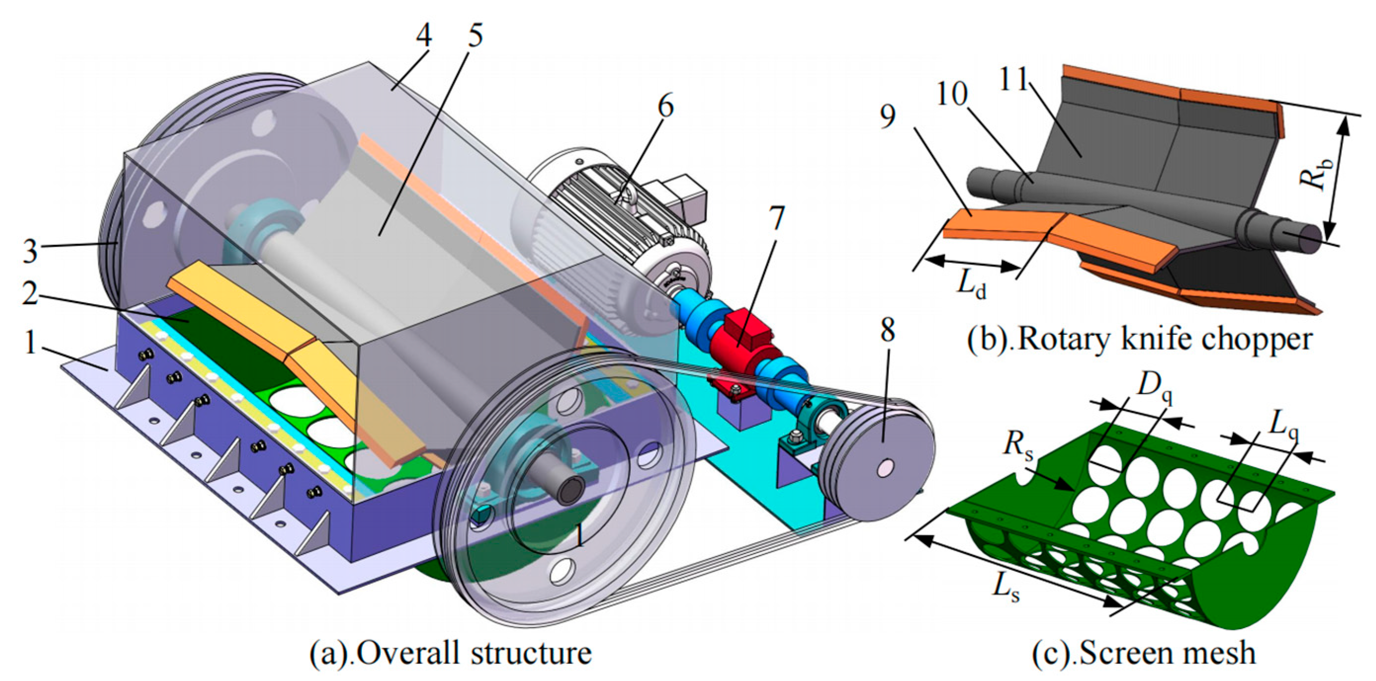
The structure of the rotary knife-type chopping mechanism is illustrated in
Figure 3. It primarily consists of a chopping motor, a torque sensor, a rotary knife chopper, stationary knives, gap adjustment components, a screen, and a frame. The stationary knives are mounted on either side of the rotary knife chopper, with the screen positioned beneath it. The rotary knife chopper includes a drive shaft, a knife holder plate, and moving knives. In conventional rotary choppers, the hollow drive shaft and parallel-aligned, untilted moving knives permit long strips of residual film to wrap around the shaft—thereby increasing cutting resistance and undermining machine stability. To address these issues and enhance cutting performance, the design employs moving knives arranged in a three-section chevron pattern along the shaft, seamlessly integrated via the knife holder plate—eliminating gaps that could trap residual film.
The configuration of the moving knives on the rotary knife chopper influences their sliding cutting performance, which in turn affects the chopping efficiency and operational power consumption of the mixed film residues [
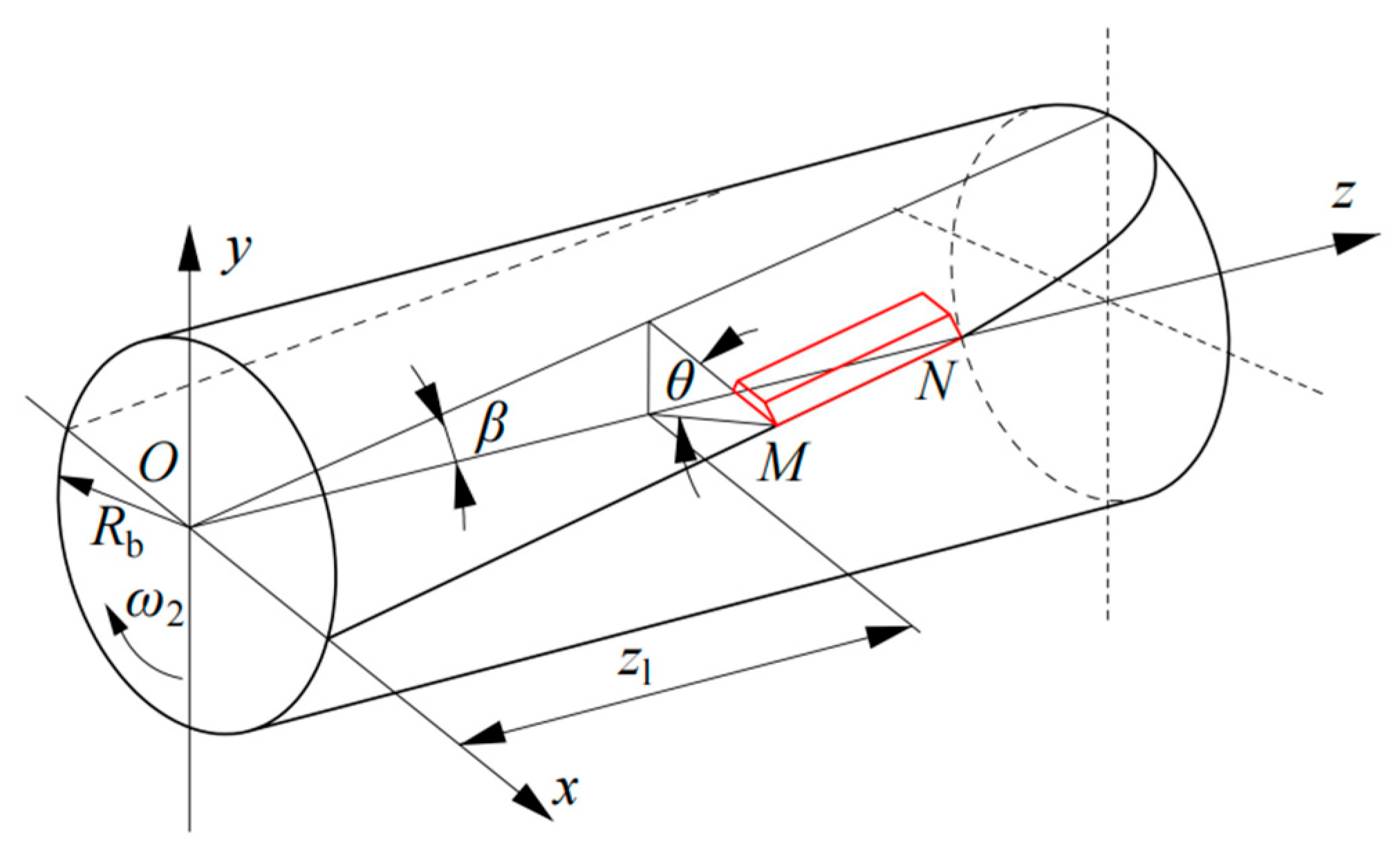
16]. The cutting edge of the moving knives can be approximated as a segment of an elliptical curve. This ellipse is formed by the intersection of the moving knife’s bottom surface and the drum’s centerline, which are inclined at a specific angle. The cutting edge curve is taken from the segment of the ellipse that is closest to a straight line, ensuring that the tip of the moving knife, point
MN, follows a cylindrical path. The cutting edge curve of the moving knife is shown in
Figure 4.
Given that the semi-major axis of the elliptical curve is
Rb/sin
β and the semi-minor axis is
Rb, the equation for the cutting edge of the moving knife is derived in the
xoz-coordinate system:
As shown in
Figure 5, the installation angle
θ of the moving knife is given by:
In Equations (5) and (6), X and Z represent the coordinates of any point on the cutting edge of the moving knife, mm; β represents the inclination angle of the elliptical plane of the moving knife relative to the central plane, (°); Rb represents the radius of the blade trajectory, mm; and θ represents the installation tilt angle of the cutting edge at point, M (°).
Based on the overall machine working width and the dimensions of the chopping chamber, the chopper width is set to 800 mm. Two sets of moving knives, totaling six knives, are symmetrically mounted on the chopper drum. Each moving knife has dimensions of 400 × 90 × 15 mm. Due to the small rotational radius of the chopper, the required material chopping length can only be achieved by increasing the rotational speed. However, increasing the speed demands higher stiffness, strength, and dynamic balance of the chopper. To address this, the rotational radius should be maximized within the available space in the chopping chamber. Therefore, the radius of the blade trajectory (
Rb) is designed to be 265 mm. Experimental studies [
17,
18] indicate that increasing the installation tilt angle (
θ) of the moving knives reduces the cutting edge angle (
η), improving chopping performance but worsening discharge performance. To balance chopping and discharge performance, the relationship between the cutting edge angle (
η) and installation tilt angle (
θ) must satisfy
η +
θ < 90°. Thus, an installation tilt angle of θ = 30° and a cutting edge angle of
η = 35° are chosen. The inclination angle (
β), constrained by the chopper’s structure, is set to
β = 5°.
The sliding cutting angle of the moving knife is a crucial factor influencing cutting resistance and specific energy consumption. An optimal sliding cutting angle can reduce both cutting resistance and the power required to process mixed film residues [
18,
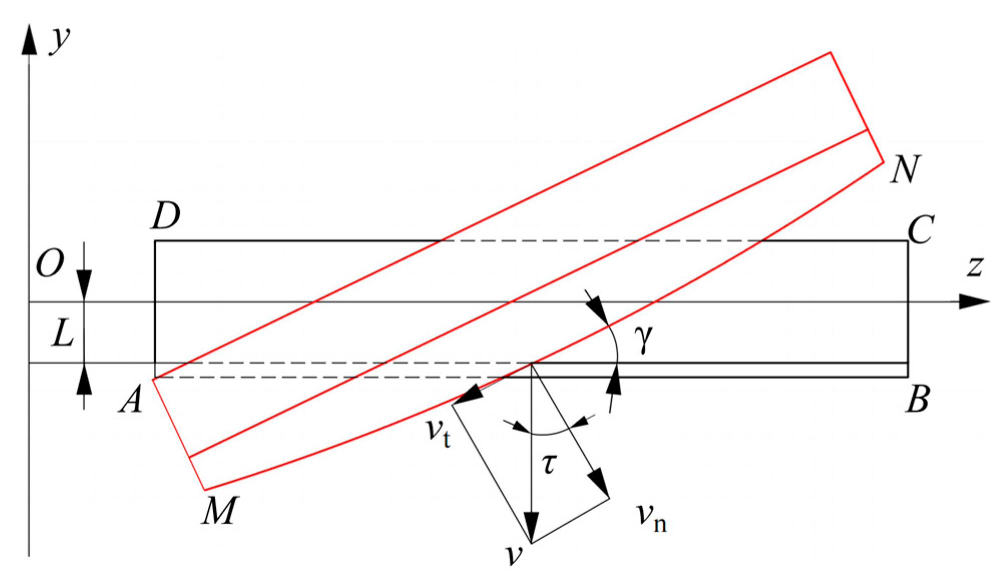
19]. During operation, the moving knife moves in a circular motion around the drive shaft. The cutting process begins when the cutting edge
MN reaches the starting point
D of the mixed film residues (
ABCD) and is completed when the moving knife reaches point B. Assuming that the moving knife
MN intersects the stationary knife
AB at point
E, the velocity
v at point
E is decomposed into the tangential velocity
vn and the sliding velocity
vt. The angle between the tangential velocity
vn and the moving knife velocity
v is defined as the sliding cutting angle (
τ), and the angle between
MN and
AB is the thrust angle (
γ). The cutting process of the moving knife is illustrated in
Figure 5.
As illustrated in
Figure 5, the sliding cutting angle (
τ) and the thrust angle (
γ) are related by the following equation:
In Equation (7), τ represents the sliding cutting angle, (°), γ represents the thrust angle, (°), and L represents the installation height of the stationary knife, mm.
As shown in Equation (7), the thrust angle (γ) is directly proportional to the sliding cutting angle (τ). An excessively large sliding cutting angle leads to an excessively large thrust angle, whereas selecting an appropriate sliding cutting angle can reduce chopping power consumption. According to the Agricultural Machinery Design Handbook, the sliding cutting angle should range from 10° to 18°, while the thrust angle should range from 4° to 8°. Given the low moisture content of the mixed film residues, a sliding cutting angle of τ = 12° and a thrust angle of γ = 5° are chosen for this design.
- 2.
Configuration and structural parameters of stationary blade
The structural dimensions of the stationary blade are identical to those of the moving blade, with a length of 400 mm, a width of 90 mm, and a thickness of 15 mm. The configuration parameters of the stationary blade include its installation height and the gap between the moving and stationary blades. The installation height refers to the relative position of the stationary blade with respect to the main axis of the chopping drum, as derived from Equation (8):
In Equation (8), L represents the installation height of the stationary blade, mm.
Given the radius of the cutting edge trajectory of the moving knife (Rb = 265 mm), the installation height of the stationary blade (L) can be calculated using Equation (8), yielding L = 32.29 mm. A value of L = 32.0 mm is selected.
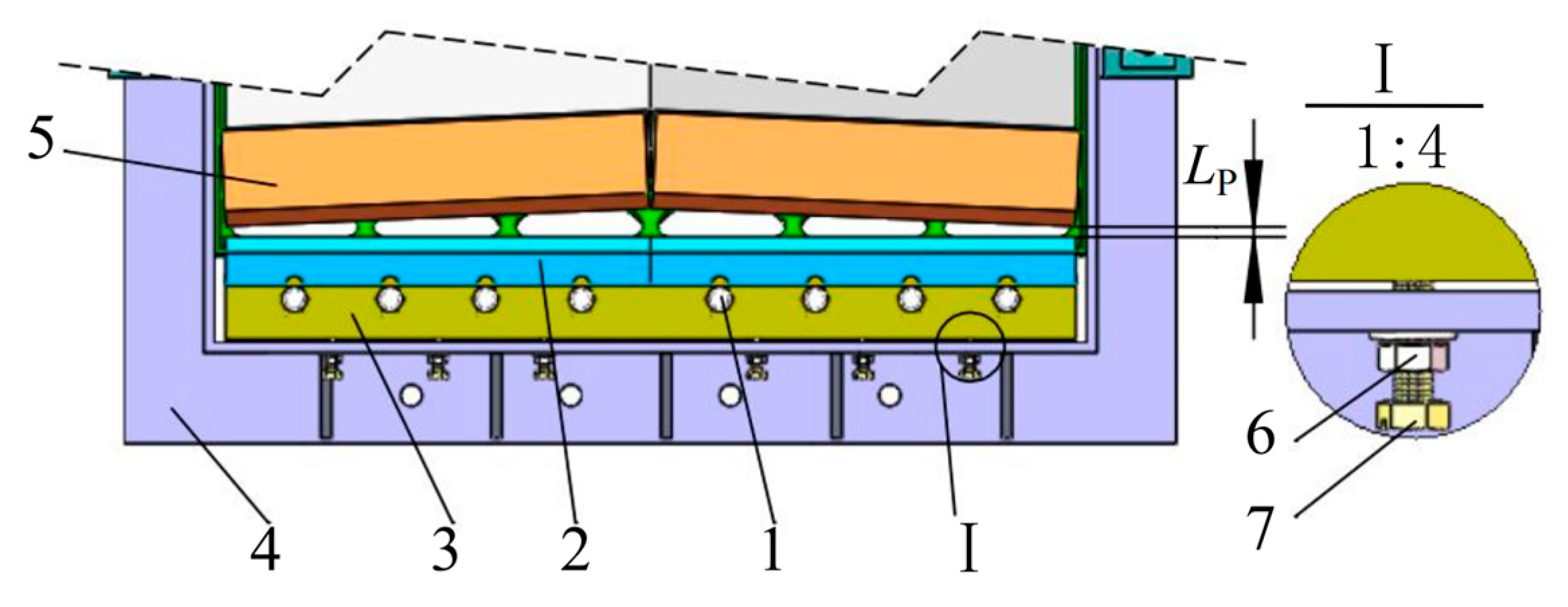
To precisely adjust the gap between the moving and stationary knives, a gap adjustment component was designed. This component primarily consists of a limit bolt, a fixing nut, and a stationary knife holder. The fixing nut is mounted on the outer side of the box-type frame, and the limit bolt passes through the nut to connect with the stationary knife holder, enabling movement. By rotating the limit bolt, the stationary knife can be adjusted, as shown in
Figure 6.
During the installation of the stationary knife, the position of the chopper is first adjusted. The limit bolt is rotated to set the gap between the moving and stationary knives to zero. The limit bolt is then rotated in the opposite direction to move the stationary knife away from the moving knife, increasing the gap until the desired value is reached. Subsequently, the locking bolt is tightened to secure the stationary knife. The gap between the moving and stationary knives (
Lp) can be calculated using Equation (9).
In Equation (9), P represents the pitch of the limit bolt, mm; n represents the number of rotations of the limit bolt.
The gap between the moving and stationary knives directly influences both material cutting length and operational power consumption [
20]. Due to the soft texture of the residual film in the mixed film residues, an excessively large gap disperses the shear force, increasing shear resistance and leading to suboptimal chopping performance. A smaller gap improves chopping performance; however, an overly small gap increases the risk of knife collisions [
21]. Based on preliminary shear force experiments with mixed film residues, the gap between the moving and stationary knives (
Lp) is set between 0.5 and 2.0 mm.
- 3.
Rotational speed of rotary knife chopper
The rotational speed of the rotary knife chopper influences the theoretical cutting length of the material, defined as the feed length during the interval between two successive cutting actions of adjacent moving knives [
22]. The rotational speed (
nb) of the rotary knife chopper is related to the following equation:
In Equation (10), va represents the feeding speed (ranging from 0.6 to 0.8 m/s); l1 represents the theoretical cutting length of the material, mm; and Z represents the number of moving knives on the circumference (Z = 3).
As shown in Equation (10), the theoretical cutting length of the material is inversely proportional to the chopper’s rotational speed. The higher the rotational speed, the more cutting actions occur per unit of time, resulting in a smaller material cutting length. Excessively large or small pieces of residual film, as well as oversized cotton stalks, hinder the subsequent separation of film-mixed residues and the water-washing process for residual film [
6,
10,
23,
24]. Based on the GB/T 37821-2019 [
25] Technical Specification for the Recycling of Waste Plastics and mixed film residue separation test results, the optimal cutting length range for residual film is 50–150 mm, while the optimal range for cotton stalks is 50–100 mm. Due to the unique ductility of residual film, under the same cutting conditions, its cutting size is always larger than that of cotton stalks. Therefore, the theoretical cutting length of the mixed film residues is designed based on the common qualified length range for both cotton stalks and residual film (50–100 mm). Substituting these parameters into Equation (10) yields a chopper rotational speed (
nb) between 120 and 320 r/min.
- 4.
Screen
As illustrated in
Figure 3c, the screen is located beneath the rotary knife chopper and functions as a secondary sizing and discharge component for the chopped film residues. Common aperture geometries include circular, square, triangular, and oblong shapes. Circular apertures were selected for their enhanced screening performance, which improves both chopping efficiency and material discharge. The aperture diameter and open area ratio are two critical structural parameters that significantly influence both chopping quality and throughput. The relationship between the theoretical chopped length (
l1) of the mixed film residues and the aperture diameter (
Dq) of the screen is expressed as follows [
26]:
The open area ratio (
K) of the screen is defined by the following equation:
In Equation (12), Dq represents the diameter of the screen aperture, mm; and Lq represents the center-to-center spacing of adjacent apertures, mm.
Considering the overall design constraints and spatial requirements of the chopping mechanism, the screen was designed with a length Ls = 820 mm and a radius Rs = 315 mm. According to Equations (11) and (12), the calculated screen aperture diameter Dk falls within the range of 58.8–133.3 mm. Taking into account the practical requirements of the shredding operation, the aperture diameter was finalized as Dq = 120 mm, the center spacing to Lq = 130 mm, and the open area ratio to K = 76.9%.The apertures are uniformly arranged in a linear pattern to ensure stable discharge and reduce the risk of clogging during operation.
- 5.
Analysis of film-mixed residue cutting resistance
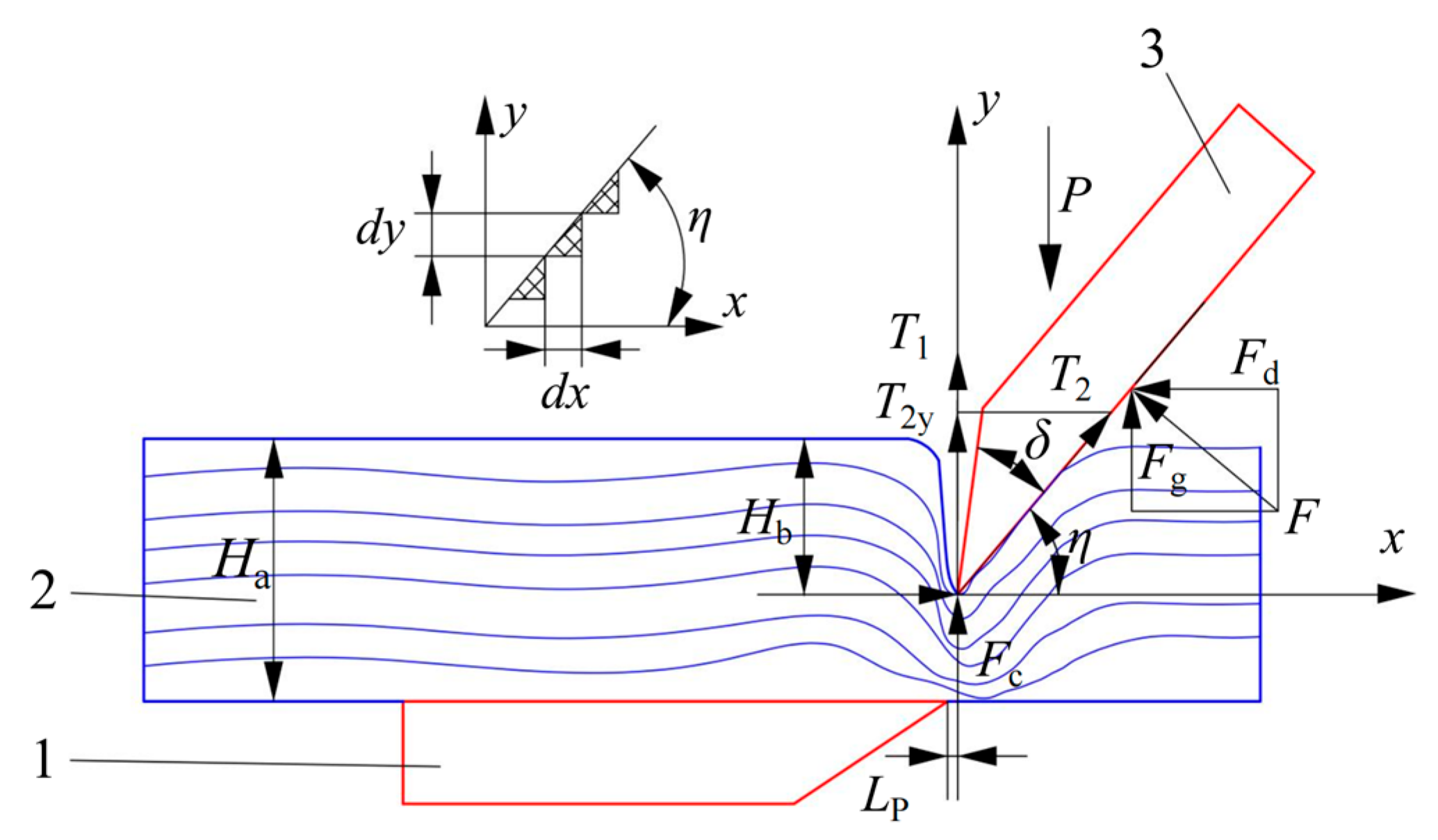
To better understand the mechanism of cutting resistance during mixed film residues processing, the composition of the cutting resistance force system at the moving knife’s cutting edge is analyzed from a microscopic perspective [
27].
As shown in
Figure 7, the reactive force (
F) acting on the moving knife during the shearing process of the film-mixed residues is expressed as follows:
Under the influence of the reactive force (
F), the vertical components of the frictional forces
T1 on the front edge and
T2 on the rear edge of the moving knife are given by
T2y:
After the film-mixed residues are compressed and deformed, the reactive force (
Fc) acting on the moving knife is expressed as:
In Equation (15), md represents the thickness of the moving knife’s cutting edge, mm; ld represents the length of the moving knife’s cutting edge, mm; and σc represents the compressive stress of the film-mixed residues, MPa.
Based on the above analysis, it can be concluded that, to complete the cutting process, the vertical force (
P) acting on the cutting edge of the moving knife must satisfy the following condition:
In Equation (16), Fc represents the reactive force exerted by the film-mixed residues on the moving knife, N; Fg represents the vertical reactive force applied by the mixed film residues to the moving knife after compression, N; Fd represents the horizontal reactive force applied by the mixed film residues to the moving knife after compression, N; and T2y represents the horizontal component of the tangential frictional force T2, N.
To determine
Fc and
Fd, it is essential to first analyze the differential forces d
Fc and d
Fd acting on the cutting edge. During the shear deformation process, assuming that the film-mixed residue unit only undergoes changes in the height direction and that its stress–strain relationship follows the generalized Hooke’s law, the stress–strain relationship during compression by the cutting edge is given by:
In Equation (17), ε represents the relative deformation; σ represents the normal stress exerted on the film-mixed residue, N/m2; E represents the elastic modulus of the mixed film residues, N/m2; Hb represents the total thickness of the mixed film residues, mm; and Ha represents the depth of compression of the mixed film residues under the cutting edge, mm.
The differential forces d
Fg and d
Fd acting on the cutting edge of the moving knife in the horizontal and vertical directions are expressed as follows:
By integrating both sides of Equation (16), we obtain:
By substituting Equations (15) and (19) into Equation (16), the vertical force(
P) acting on the moving knife in the horizontal direction is derived as follows:
In summary, to achieve efficient chopping of film-mixed residues, the vertical force applied to the moving knife must surpass the cutting resistance force. Cutting resistance force is influenced not only by the physical properties of the mixed film residues (such as elastic modulus, compression/shear stress, Poisson’s ratio, and thickness), but also by the structural parameters of the cutting edge (such as edge thickness and the effective length of the moving knife). Additionally, it is affected by the speed of the moving knife and the gap between the moving and stationary knives. To minimize cutting resistance force and reduce operational power consumption, the mechanical model of cutting resistance force should be integrated with all influencing factors.
- 6.
Vibration characteristics analysis of chopper
During normal operation, the chopper is subjected to significant impact forces. If the frequency of the dynamic load from these impacts aligns with or closely matches the chopper’s natural frequency in a specific mode, resonance may occur, leading to variations in the gap between the moving and stationary knives and potentially causing structural fatigue. This can adversely affect the chopper’s performance, service life, and safety [
28]. To evaluate its safety and design feasibility, a modal analysis of the chopper was performed using ANSYS 2022R2 software, which provided its natural frequencies and maximum displacement deformation. The chopper’s 3D model, created in SolidWorks 2021, was imported into ANSYS’s modal module. The moving knife material was set to 65Mn, and the transmission shaft and support plate were made from Q235, with material properties listed in
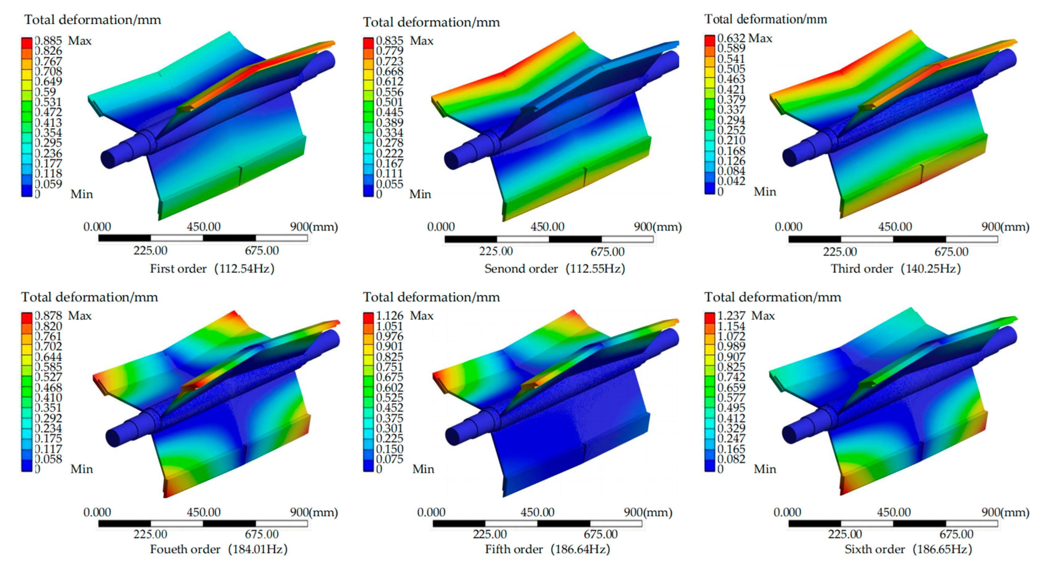
Table 2. The SOLID92 mesh type was used for meshing, and fixed supports were applied at both ends of the chopper. The results of the first six vibration modes are presented in
Table 3 and
Figure 8.
As shown in
Table 3, The results of the first six mode shape analyses of the chopper, the first six natural frequencies of the chopper range from 112.54 to 186.65 Hz, with the maximum deformation ranging from 0.885 to 1.237 mm. As the mode number increases, both the natural frequency and maximum deformation reach their highest values in the sixth mode. The first mode exhibits the lowest natural frequency, while the third mode shows the smallest maximum deformation. From
Figure 8, it is evident that, in the first mode shape, the largest displacement deformation occurs in the first and second rows of the moving knives; in the second mode shape, the greatest deformation is seen in the second row; in the third mode shape, displacement deformation occurs across all rows from the first to the third, which explains the smallest deformation. In the fourth and fifth mode shapes, the maximum deformation occurs at the sides of the first and second rows of the moving knives. In the sixth mode shape, the maximum deformation is observed at the sides of the third row of the moving knives. The operational rotational speed of the chopper is set to 120–320 r/min, producing an excitation frequency range of 2 to 5.33 Hz, which is much lower than the first natural frequency of the chopper (112.54 Hz). Therefore, the designed chopper effectively avoids resonance.


