Article

Parameter Calibration and Experimental Study of a Discrete Element Simulation Model for Yellow Cinnamon Soil in Henan, China

College of Agricultural Equipment Engineering, Henan University of Science and Technology, Luoyang 471003, China
*
Author to whom correspondence should be addressed.
Agriculture 2025, 15(13), 1365; https://doi.org/10.3390/agriculture15131365
Submission received: 29 May 2025 / Revised: 18 June 2025 / Accepted: 23 June 2025 / Published: 25 June 2025
(This article belongs to the Section Agricultural Technology)

Abstract

To investigate the interaction mechanism between agricultural tillage machinery and soil, this study established a precise simulation model by integrating physical and numerical experiments using typical yellow cinnamon soil collected from western Henan Province, China. The discrete element parameters for soils with varying moisture contents were calibrated based on the Hertz–Mindlin (no slip) contact model. Through Plackett–Burman screening, steepest ascent optimization, and Box–Behnken response surface methodology, a predictive model correlating moisture content, parameters, and repose angle was developed, yielding the optimal contact parameter combination: interparticle static friction coefficient (0.6), soil–65Mn static friction coefficient (0.69), and interparticle rolling friction coefficient (0.358). For the Bonding model, orthogonal experiments coupled with NSGA-II multi-objective optimization determined the optimal cohesive parameters targeting maximum load (673.845 N) and displacement (9.765 mm): normal stiffness per unit area (8.8 × 10⁷ N/m3), tangential stiffness per unit area (6.85 × 10⁷ N/m3), critical normal stress (6 × 10⁴ Pa), critical tangential stress (3.15 × 10⁴ Pa), and bonding radius (5.2 mm). Field validation using rotary tillers and power harrows demonstrated less than 6% deviation in soil fragmentation rates between simulations and actual operations, confirming parameter reliability and providing theoretical foundations for constructing soil-tillage machinery interaction models.

1. Introduction

The yellow cinnamon soil region is a crucial dryland agricultural area in Henan Province, China. It is distinguished by its clayey texture and compact structure, which often results in adhesion, wear, fracture, and other issues in soil-engaging components during field operations, thereby diminishing the tillage quality [1]. Given the inherent mechanical properties of yellow cinnamon soil, optimizing the design of key soil-engaging components and developing high-performance tillage machinery is vital. Structural and operational parameters must be adjusted to specific soil conditions in order to achieve optimal performance during machinery operations. Due to the complexity of field testing and challenges in parameter acquisition, simulation trials have become a primary method for identifying the main factors affecting operational quality.
The discrete element method (DEM) is widely used to analyze interactions between granular materials and agricultural implements, playing a crucial role in optimizing the design of tillage machinery [2]. For soil-tool interaction simulations, selecting appropriate contact models based on soil characteristics is essential, and calibrating critical model parameters is necessary to ensure simulation accuracy and fidelity. Previous studies have utilized the DEM for soil simulations. An optimization method combining the Plackett-Burman test, the steepest ascent test, and the central composite test was proposed by Zhou et al. [3] in order to determine DEM parameters for paddy soil with a high moisture content (>40%), so as to accurately predict its properties and disturbance behavior. A multi-scale mechanical parameter calibration framework for soil particles was developed by Ucgul et al. [4] through integration of the Hertz-Mindlin nonlinear contact model with a hysteretic spring damping model, in which key contact parameters were rigorously calibrated. The particle contact model proposed by Li, Shoutai et al. [5] was developed using the Hertz-Mindlin with JKR cohesion model. Soil parameters were determined through bulk density tests, particle size distribution analyses, and static/dynamic repose angle tests. Parameter optimization was conducted using the Plackett–Burman, steepest ascent, and Box–Behnken designs. This research established accurate parameters and a validated interaction model for the DEM simulation of cultivated purple soil. The discrete element input parameters were calibrated using a hysteresis spring contact model and linear cohesive model according to Kojo Atta Aikins et al. [6], with the performance of the trencher being reliably verified by applying these calibrated parameters in cohesive soil simulations. The parameter calibration of the discrete element simulation model for brick red soil particles in Hainan’s hot zone was completed by Jie et al. [7], providing critical data support for the development of agricultural machinery soil contact components tailored to the soil quality characteristics of Hainan.
As one of the 12 most widely distributed typical soil types in China, yellow cinnamon soil exhibits pronounced regional concentration in Henan Province. Its characteristics of heavy clay texture and compact structure lead to unique regional variability in the mechanical properties of soils in western Henan. Current research still presents gaps in parameter calibration for yellow cinnamon soils in this region. Moreover, studies on the relationship between moisture content and soil–contact parameters remain insufficient to address practical tillage conditions. This paper integrates significance analysis and response surface methodology to calibrate and optimize DEM parameters for western Henan’s yellow cinnamon soil using field experiments and simulations. Based on the Hertz–Mindlin with bonding contact model in EDEM, a quantitative relationship between soil moisture content and contact parameters was established using the lifted cylinder method, enabling the accurate prediction of contact parameters based on water content. Subsequently, confined uniaxial compression tests were conducted to determine the bonding parameters. Finally, a discrete element method model for yellow cinnamon soil particles in western Henan was developed and validated through field experiments. This study provides a fundamental basis for research on tillage implements and agricultural machinery.

2. Materials and Methods

2.1. Test Material Characteristics

The test soil was sampled from the Smart Agricultural Farm in the Yibin District of Luoyang City, Henan Province, China, located at coordinates 112°35′55″ N and 34°33′11.5″ E, as illustrated in Figure 1. Soil samples were collected from the 0–200 mm tillage layer in the same experimental field using a five-point sampling method. A cutting ring method [8] was employed to obtain undisturbed soil cores for subsequent moisture content determination. Prior to sampling, surface straw residues at each sampling point were carefully removed. The inner wall of the cutting ring was uniformly coated with vaseline, and the ring was vertically positioned on the soil surface. A hammer was used to gently drive the ring into the soil by striking the handle mounted on top. When the ring edge was slightly below the soil surface, the surrounding soil was cleared, and the ring was carefully extracted. Excess soil was trimmed to ensure flat surfaces at both ends of the ring. One sample was collected per sampling point, totaling five replicates. The Soil Mechanics Laboratory Manual was consulted to determine the soil moisture content through the oven-drying method, yielding an actual soil moisture content of 17.3%.

2.2. Soil Moisture Content Calibration

According to national standards such as GB/T 5668-2017 [9] and GB/T 25420-2021 [10], the soil moisture content must be below 25% during the operation of tillage machinery. Considering the significant impact of soil moisture content on the mechanical properties of particle-to-particle contact, this study systematically designed soil samples with a moisture gradient with levels of 0%, 4%, 8%, 12%, 16%, 20%, and 24% for experimental analysis. Oven-dried soil underwent moisture content calibration, setting the target total mass of the soil–water mixture at 2.5 kg. The masses of the dry soil and pure water were calculated based on this total mass, and thorough mixing was achieved by spraying water onto the agitated soil using a spray bottle. Figure 2a illustrates the soil moisture calibration process, while Figure 2b displays the final 2.5 kg soil sample with calibrated moisture content.

2.3. Physical Experiment for Angle of Repose Calibration

The soil repose angle is a critical indicator for evaluating soil strain characteristics during interactions between soil-engaging components of agricultural machinery and the soil, necessitating the precise measurement of this parameter. The contact parameters are typically calibrated using angle of repose tests [11]. The widely used cylinder lifting method was adopted as a technical approach to quantify the repose angles of soil in this study. The experimental cylinder, (manufactured in Mengjin County, Luoyang City, Henan Province, China), which was made from 65Mn steel to match the material of tillage machinery soil-engaging components, had the dimensions of 100 mm (diameter) by 350 mm (length) (Figure 3). The test soil was loaded into the cylinder and, after complete filling, the bottom cover was quickly removed as the universal testing machine was started. The cylinder was lifted upward at a constant velocity of 100 mm/min, allowing the soil particles to flow freely under gravity. The repose angle was determined as the angle between the horizontal plane and the stabilized soil slope surface. Each moisture content trial was replicated five times.

2.4. Physical Experiment for Uniaxial Compressive Strength Determination

As illustrated in Figure 4, during the soil compaction phase of the uniaxial compression physical test, an appropriate amount of petroleum jelly was applied to the inner wall of a plexiglass cylinder (inner diameter: 135 mm; outer diameter: 145 mm; height: 360 mm;manufactured in Mengjin County, Luoyang City, Henan Province, China) in order to minimize friction between the soil and the cylinder wall, facilitating the subsequent extraction of samples for uniaxial compression testing. Soil samples with 4, 8, 12, 16, 20, and 24% moisture content were sequentially loaded into the cylinder for compaction. The compaction process was terminated when the compression platen of the universal testing machine descended, compressing the soil by 120 mm.
After completing the compaction process, the hoop clamp was cautiously removed from the plexiglass cylinder, and the cylindrical walls were systematically disassembled from both ends while preserving the integrity of the soil specimen. The universal testing machine engaged the base platen to apply axial compressive loading at a controlled displacement rate of 10 mm/min, with displacement measurement automatically being activated upon detecting a 5 N preload threshold. Testing continued until the specimen failed, at which point the moisture content measurements were stopped. The key experimental data recorded included maximum compressive force at peak stress and corresponding displacement strain at failure initiation. Each moisture content treatment group underwent five replicate tests to ensure reproducibility and statistical validity.

2.5. Discrete Element Method Contact Model Selection

In discrete element simulations of soil–tool interactions using the EDEM 2020 software, the choice of contact models directly influences the calculation of particle forces and moments, requiring customized model configurations for specific simulation objectives. The accuracy of the simulation results is heavily reliant on the proper calibration of the contact models [12]. The EDEM platform includes a range of contact models, such as (1) Hertz–Mindlin (no slip), (2) Hertz–Mindlin with bonding, (3) JKR, (4) linear cohesion, (5) linear spring, and (6) moving plane formulations.
The Hertz–Mindlin (no slip) model was selected as the contact model for interactions between soil particles and 65Mn steel in DEM simulations, as heat transfer and wear considerations were not incorporated into this study. This model offers a computationally efficient framework for noncohesive granular assemblies while preserving accuracy in normal/tangential force transmission. The Hertz–Mindlin with bonding model was applied using time-dependent bonding parameters to address interparticle cohesion in moist soil matrices. The bonding forces Fn and and moments Mn and of the soil particles increase from zero at each time step based on the following equations [13,14].
δ F n = V n S n A δ t
δ F t = V t S t A δ t
δ M n = ω n S t J δ t
δ M t = ω t S n J 2 δ t
A = π R b 2
J = 1 2 π R b 4
where δ F n is the normal stress of the particle bond, (N); δ F is the tangential stress of the particle bond, (N); δ M n is the normal bending moment of the particle bond, (N·m); δ M t is the tangential torsional moment of the particle bond, (N·m); V n is the normal velocity component of the particle, (m/s); V t is the tangential velocity component of the particle, (m/s); S n is the normal stiffness of the bond, (N); S t is the tangential stiffness of the bond, (N); ω n is the normal angular velocity of the particle, (rad/s); ω t is the tangential angular velocity of the particle, (rad/s); A is the contact area, (mm2); J is the polar moment of inertia of the bonded spherical volume, (m4); R b is the bond radius, (mm); and δ t is the time step, (s).
When external forces acting on the bond exceed a critical threshold, bond rupture will occur, with the essential conditions of failure being defined by Equation (8).
σ max < F n A + 2 M t J R b
τ max < F n A + M n J R b
Upon bond rupture induced by external forces, interparticle interactions will no longer be governed by cohesive bonding effects, as required for academic publication.

3. Results

3.1. Physical Experimental Results of Soil Angle of Repose

Following particle stabilization, high-speed camera recordings captured soil accumulation patterns under varying moisture gradients, and subsequent image analysis was performed at the acquisition port to quantify the repose angles. Representative soil images for the different moisture gradients are shown in Figure 5.
The angle of repose is primarily determined using image processing techniques. The methodology includes edge detection of accumulated soil profiles, the extraction of angular boundaries through threshold segmentation, and linear regression analysis to derive slope gradients for angle calculation [15]. MATLAB 2020 was utilized to process the soil accumulation images systematically. The complete workflow, as demonstrated in Figure 6, allowed for the quantification of angles of repose for soil with varying moisture contents; the results are summarized in Table 1.

3.2. Simulation Results of Soil Angle of Repose

To establish the relationship between the angle of repose and discrete element method parameters in numerical simulations, a Plackett–Burman design was first employed to reduce the number of factors through 12 experimental runs. Factors with p < 0.05 were identified as statistically significant and selected for subsequent optimization.
The steepest ascent method was then applied to progressively adjust factor levels, rapidly approaching the optimal response region while narrowing the level ranges. This provided refined factor level settings for the subsequent Box–Behnken design (BBD).
The BBD adopted a three-factor, three-level experimental scheme to establish a second-order polynomial model. An analysis of variance (ANOVA) was performed to validate model significance and quantify the relationship between the soil angle of repose and simulation parameters.
Furthermore, a fitted relationship between moisture content and angle of repose was developed based on physical experiments. By coupling the mathematical models of (1) parameters versus angle of repose and (2) moisture content versus angle of repose, the quantitative relationship between the moisture content and DEM parameters was ultimately derived.

3.2.1. Plackett–Burman Test

The soil model was represented by fundamental spherical particles with radii of 5 mm. The cylindrical container was fabricated from 65Mn steel with the following material properties: Poisson’s ratio = 0.29; density = 7861 kg/m3; and shear modulus = 7.9 × 10¹⁰ Pa. The SolidWorks 2023 3D model was imported into the EDEM 2020 software for particle generation, followed by a stabilization period of three seconds after complete particle sedimentation. Post-simulation, image analysis was performed on X-directional and Y-directional cross-sections of the soil cone [16], yielding four angular measurements (θ1X, θ2X, θ1Y, and θ2Y). The final angle of repose was determined as the arithmetic mean of the measurements. The simulation workflow and angular extraction procedure are shown in Figure 7 and Figure 8, respectively.
Nine intrinsic and contact parameters were selected as experimental factors for the Plackett–Burman design, as follows: (1) coefficient of restitution between soil particles, (2) coefficient of static friction between soil particles, (3) coefficient of rolling friction between soil particles, (4) coefficient of restitution between soil particles and 65Mn, (5) coefficient of static friction between soil particles and 65Mn, (6) coefficient of rolling friction between soil particles and 65Mn, (7) Poisson’s ratio of soil particles, (8) shear modulus of soil particles, and (9) density of soil particles. This design allows for the preliminary identification of critical parameters through comparisons of high and low levels. The optimal factors were selected for subsequent experiments based on an analysis of inter-domain effects, significance testing, and practical engineering considerations [17]. Parameter-level assignments were determined according to the established literature [18,19,20,21,22], with a summary of factor ranges provided in Table 2.
Table 3 presents the Plackett–Burman experimental results. The statistical analysis was performed using the Design-Expert 13 software through an analysis of variance, yielding a significance-based ranking of factor effects on the angle of repose of soil particles, as summarized in Table 4.
As shown in the Pareto chart of the experimental results (Figure 9), the contribution rates of the individual factors displayed clear hierarchical patterns. The significance ranking of the factor effects on the angle of repose was as follows: B > E > C > I > A > G > F > H > D. Contribution rates directly reflect their magnitude of influence. Notably, the soil particle–particle static friction coefficient (B) (p = 0.0059 < 0.01), the soil particle–65Mn static friction coefficient (E) (p = 0.0149 < 0.05), and the soil particle–particle rolling friction coefficient (C) (p = 0.0378 < 0.05) showed statistically significant effects, with contribution rates of 51.95%, 20.31%, and 7.73%, respectively. In contrast, factors I, A, G, F, H, and D had non-significant impacts on the angle of repose. Consequently, factors B, E, and C were chosen for the subsequent steepest ascent experiments.

3.2.2. Steepest Ascent Test

Steepest ascent experiments were performed on the statistically significant factors identified through Plackett–Burman screening, aiming to narrow down the optimal factor level ranges. For non-significant factors (I, A, G, F, H, D), midpoint values were adopted as follows: 1940 kg/m3 for particle density, 0.35 for coefficient of restitution between soil particles, 0.325 for Poisson’s ratio, 0.205 for rolling friction between soil particles and 65Mn, 1.995 MPa for shear modulus, and 0.38 for coefficient of restitution between soil particles and 65Mn. The experimental results are summarized in Table 5.
The soil physical tests conducted across a moisture content range of 4–24% yielded angle of repose values of 31.33°, 32.7°, 34.64°, 35.09°, 35.58°, and 36.44°. Consequently, the angle of repose values ranging from 32.03° to 35.90° from the steepest ascent experiments were selected to represent practical soil behavior. The Box–Behnken design was implemented with the following factor ranges: soil particle–particle static friction coefficient (B) of 0.5–0.7, soil particle–65Mn static friction coefficient (E) of 0.25–0.4, and soil particle–particle rolling friction coefficient (C) of 0.5–0.7.

3.2.3. Box–Behnken Test

The Box–Behnken experimental design was implemented following steepest ascent optimization to establish a predictive model relating the angle of repose to DEM simulation parameters. This three-factor, three-level design adhered to response surface methodology principles, with factor-level ranges determined through the prior path of steepest ascent experiments. The experimental matrix and corresponding results are presented in Table 6 and Table 7, respectively.
Through the analysis of variance module of the Design-Expert 13 software, a variance analysis and multiple regression analysis were performed on Box–Behnken experimental data for soil angle of repose simulation. A quadratic polynomial regression model was developed, as shown in Equation (9), enabling the prediction of response values at specified factor levels using the coded factor notation.
Y = 33.835 + 1.95625 B + 1.10875 C + 1.16 E 0.3125 B C + 0.2 B E + 0.53 C E 0.72125 B 2 1.45125 C 2 0.96375 E 2
The regression model achieved a coefficient of determination (R2) of 0.9784, with an adjusted R2 of 0.9460 and a predicted R2 of 0.7735. The difference between adjusted and predicted R2 values was less than 0.2, indicating acceptable model predictability. The model was analyzed for variance; the results are summarized in Table 8.
As shown in Table 8, the results of the analysis of variance for the angle of repose regression model indicate the following: (1) the model p-value = 0.0001 < 0.01, confirming overall statistical significance, and (2) the lack-of-fit p-value = 0.5046 > 0.1, verifying an adequate model fit without systematic deviation. Factor analysis revealed the following: (1) primary factors B (coefficient of the static friction between soil particles), E (coefficient of static friction between soil particles and 65Mn), and C (coefficient of rolling friction between soil particles) exhibited highly significant effects (p < 0.01); (2) the interaction term EC showed a significant effect (p < 0.1), while the interaction terms BE and BC remained non-significant (p > 0.1); and (3) the quadratic terms E2 and C2 demonstrated highly significant nonlinear effects (p < 0.01), with B2 showing moderate significance (p < 0.05). The three-dimensional response surface and the contour plot are illustrated in Figure 10.

3.2.4. Angle of Repose Model Validation with Discrete Element Parameters

Using the angle of repose measurements from physical tests across varying moisture contents as reference points, a parameter optimization protocol was implemented to calibrate six sets of DEM parameters—the coefficient of static friction between soil particles (B), the coefficient of static friction between soil particles and 65Mn (E), and the coefficient of rolling friction between soil particles (C). The simulated results were rigorously validated against the physical tests in Figure 11, with the calibrated parameters being summarized in Table 9, confirming the model’s reliability.
As shown in Figure 12, a comparative analysis of the simulated and physical angle of repose measurements across the moisture content range of 4–24% revealed a mean relative error of 2.26% (<5%), confirming the robustness and predictive reliability of the established discrete element model. This high degree of accuracy strongly supports the conclusions of the research.

3.2.5. Moisture Content and Discrete Element Parameter Modeling

A moisture content–angle of repose fitting model was established using experimentally determined values across the moisture content range. As shown in Figure 13, the simple linear regression equation is Y = 30.5018 + 0.2665X (R2 = 0.9559), while the polynomial regression equation is Y = 30.0117 + 0.3851X – 0.00179X2 – 0.000139X3 (R2 = 0.9862). Within the 4–24% moisture content range, the polynomial model demonstrates a significantly higher accuracy, as evidenced by the 3.1% improvement in R2 value compared to the linear model, thereby highlighting its superiority.
A novel moisture–DEM parameter coupling model was developed by integrating the Box–Behnken experimental design-derived angle of repose model with the moisture content–angle of repose relationship. This model establishes quantitative links between the moisture content and three critical DEM parameters—the coefficient of static friction between soil particles (B), the coefficient of static friction between soil particles and 65Mn (E), and the coefficient of rolling friction between soil particles (C). The model can be expressed as follows:
Y = 30.0117 + 0.3851 X 0.00179 X 2 0.000139 X 3 = 33.79 + 2.04 B 1.12 C + 1.05 E 0.3 B C 0.015 B E + 0.0925 C E 0.7162 B 2 1.39 C 2 0.6038 E 2
Target   Y 0.5 B 0.7 0.5 E 0.7 0.25 C 0.4
Based on the model analysis results, the optimization function of the Design-Expert 13 software was employed to optimize parameters, using the repose angle as the target value to establish a target function model. With the field-measured moisture content of 17.3% as a baseline, a soil-fitted repose angle of 35.42° was achieved through the developed model. Parameter optimization was then carried out with this fitted repose angle as the optimization target, and the optimal parameter values for the soil simulation under actual moisture content conditions are displayed in Table 10. Verification simulations were conducted using the optimized parameters, resulting in a soil repose angle of 34.84° in the simulation tests.

3.3. Uniaxial Compression Testing Results

3.3.1. Uniaxial Compression Simulation Model Development

Uniaxial compression simulation tests were conducted on the soil specimens to establish a simulation model for the soil particle bonding parameters and to identify the optimal parameter combination. As illustrated in Figure 14, the experimental setup consisted of upper and lower circular plates made of 65Mn steel. The upper plate was moved downward at a constant velocity of 10 mm/min in order to simulate the compression process, while the lower plate remained stationary. Based on the previous literature [23,24,25,26], the initial range of soil bonding parameter values was determined, and subsequent preliminary simulations narrowed these ranges, as shown in Table 11. This study employed a hybrid experimental design that combined uniform design experiments with the orthogonal array L16 (45) in order to optimize parameter combinations during soil specimen fracture. The maximum load and corresponding displacement were selected as the response variables. This systematic and efficient experimental approach aimed to determine the optimal parameter set while minimizing the number of test iterations and enhancing experimental efficiency. Detailed experimental designs and results are presented in Table 12.
The results of the analysis of variance in Table 13 indicate that the overall experimental model is statistically significant (p < 0.05). This regression model shows excellent goodness-of-fit, allowing for the accurate quantification of parameter relationships between the experimental variables and evaluation metrics.
Regression analysis techniques were used to analyze the experimental data systematically, and optimization algorithms were employed to identify the optimal parameter configuration of bonding variables. The multivariate linear regression analysis of the test results was performed using the Origin 2024 software, producing the regression equations between bonding parameters and maximum load/displacement, as follows:
D i s = 44.39 0.0053 A 1.8505 B 0.3383 C + 2.3432 D 5.2188 E
T = 2215.557 + 88.117 A 170.572 B 25.604 C + 332.817 D 392.834 E

3.3.2. Bonding Parameter Determination and Validation

The NSGA-II optimization algorithm, a multi-objective evolutionary algorithm rooted in genetic algorithms, was employed to tackle conflicting objective functions and to produce a set of trade-off solutions [27]. Therefore, this study employed the NSGA-II optimization algorithm with a population size of 100, iteration count of 100, and crossover probability of 0.9. Using the maximum load of 673.845 N and corresponding displacement of 9.765 mm obtained from physical experiments as target values, the optimal combination of bonding parameters was determined through parameter optimization: normal stiffness per unit area of 8.8 × 10⁷ N/m3, tangential stiffness per unit area of 6.85 × 10⁷ N/m3, critical normal stress of 6 × 10⁴ Pa, critical tangential stress of 3.15 × 10⁴ Pa, and bonding radius of 5.2 mm.
Validation experiments incorporated the optimized parameters into the bonding model. As shown in Figure 15, the displacement–load curves from the simulation and physical tests demonstrate close agreement. The relative errors for load and displacement were 3.894% and 4.65%, respectively. The simulation results show a maximum load of 663.0916 N (9.622 mm displacement), compared to 673.845 N (9.765 mm displacement) in the physical tests. This corresponds to maximum load and displacement errors of 1.596% and 1.464%, respectively.
Three distinct deformation stages were observed. Stage I exhibited a gradual load increase with slight fluctuations at crack initiation points in both the simulation and physical tests. Stage II showed sustained load growth after crack formation until complete failure, with consistent upward trends in both test types, while Stage III revealed rapid load decay following total fragmentation and detachment from the loading platen, with matching decay rates between the simulation and experiment. The minimal discrepancies and consistent trend alignment across all three stages confirm the calibration accuracy of the bonding model parameters.
High-speed photography is widely used for validating deformation in DEM simulations, allowing for frame-by-frame comparisons of crack propagation patterns between the experimental and numerical results [28]. High-speed imaging was utilized to document the deformation process of soil specimens under compression in this study. As shown in Figure 16, axial compression induces sequential deformation stages. During the compression phase, the platen moved downward at a constant speed of 10 mm/min. Cracks gradually appeared on the surface of the soil block, propagating from both ends toward the center. At this point, the crushing phase commenced. As the platen continued its downward motion, the cracks expanded further until the soil block fragmented and collapsed, marking the end of the crushing phase. In the unloading phase, the soil block gradually separated from the platen, resulting in a continuous reduction in the load applied to the platen until complete detachment was achieved.
Both physical and simulation tests demonstrate identical load–displacement trends (initial load increases followed by a sharp decay) and consistent failure modes—crack initiation at specimen extremities, diagonal crack coalescence, and axial splitting failure. The correlation between experimental and numerical deformation patterns and fracture mechanisms validates the calibration of the DEM against soil specimen behavior.
This study confirmed the high reliability of the bonding mechanical parameters derived from uniaxial compression tests, as validated through coupled load–displacement–deformation tests on soil specimens. These parameters provide fundamental support for simulating tillage machinery operations in agricultural engineering applications.

3.4. Results of Model Validation

3.4.1. Establishment of a Simulation Model for Yellow Cinnamon Soil in Henan Province

To verify the reliability of soil parameters, a soil bin model was created using the optimal parameters derived from experimental calibration. A virtual tillage implement was integrated into this model to conduct simulation tests, with results subsequently being compared to those of field experiments. The model was considered validated and reliable when discrepancies between simulation and field measurements remained below 10%.
Based on the aforementioned calibration tests, the combined discrete element simulation model for loose and agglomerated soils was developed in EDEM 2022. The soil particle size was set to 5 mm, with soil bin dimensions specified as 2500 mm (length) × 1000 mm (width) × 250 mm (height). The soil bonding parameters are outlined in Table 14 and Table 15.
In this study, a discrete element modeling (DEM) framework for field soil was established based on the Hertz–Mindlin (no slip) contact model with bonding using the EDEM 2020 software platform. The model accurately characterized the physicomechanical properties of the soil through refined parameter calibration processes, providing a robust technical foundation for simulating tillage machinery operational processes.

3.4.2. Validation of Field Trials

For a further validation of the calibrated parameters’ accuracy and reliability, field experiments were performed using a 1GQNJS-250 rotary tiller and 1BQ-3.0 power harrow, (manufactured by Nonghaha Group, Shijiazhuang, Hebei Province, China), with soil fragmentation rate during operation as the response variable, followed by comparative analysis between field-measured results and simulation outputs.
In the test field, five 500 mm × 500 mm sampling quadrats were established using the five-point method to collect intact soil samples from the entire tillage layer (0–150 mm depth). Following natural air-drying, soil aggregates were fractionated through a standard 4 mm sieve, with the mass of aggregates <4 mm precisely measured. The field-measured soil fragmentation rate of the rotary tiller was calculated as 85.68% using Equation (14), while the simulation yielded a 90.54% fragmentation rate based on computational analysis of bonding failure within the designated test zone. The comparative performance evaluation between field operations and simulation outputs is presented in Figure 17.
Fragmentation   Rate = M 4 cm M total × 100 %
Five 500 mm × 500 mm sampling quadrats were established in the test field using the five-point method to collect undisturbed soil samples from the complete tillage layer (0–200 mm depth). After natural air-drying, soil aggregates were fractionated through a standard 5 mm test sieve, with the mass of aggregates <5 mm accurately measured. The field-measured soil fragmentation rate of the power harrow was calculated as 90.83% using Equation (15), while the simulation results showed a 96.04% fragmentation rate based on the computational analysis of bonding failure within the specified test region. The comparative performance evaluation between field measurements and simulation outputs for the power harrow is presented in Figure 18.
Fragmentation   Rate = M 5 cm M total × 100 %
In summary, the errors between field and simulation trials for the rotary tiller and power harrow did not exceed 6%, confirming the accuracy of the soil model. This validation offers a solid technical foundation for simulation analyses of operational processes in tillage machinery. Potential error sources in field validation may include: (1) uncontrollable random errors inherent to experimental measurements, and (2) environmental complexity of field conditions where extraneous materials (e.g., stones) within sampling areas may introduce systematic bias to the results. These factors collectively contribute to observed discrepancies between field measurements and theoretical expectations.

4. Discussion

4.1. Effects of Moisture Content on Soil Angle of Repose

The influence of moisture content on soil accumulation characteristics was systematically investigated through physical tests of soil angle of repose. Experimental groups with moisture contents of 4%, 8%, 12%, 16%, 20%, and 24% were established, along with a control group. The results demonstrate a monotonic increase in the angle of repose as moisture content rose from 0% to 24%. The fundamental mechanism lies in moisture’s effect on friction coefficients between soil particles and between soil particles and tillage tools (65Mn steel). The parameter sensitivity analysis revealed the dominant factors influencing the angle of repose in descending order: static friction coefficient between soil particles (B), static friction coefficient between soil particles and 65Mn steel (E), and rolling friction coefficient between soil particles (C). The specific effects were quantified as: (1) The angle of repose increased monotonically with static friction coefficient B within 0.5–0.7; (2) For coefficient E (soil-65Mn) in 0.5–0.65, the angle increased with E, but decreased when E exceeded 0.65; (3) Rolling friction coefficient C showed positive correlation with the angle within 0.25–0.35, turning negative beyond 0.35. This analysis indicates that increasing moisture content continuously enhances interparticle static friction, while particle–tool static friction and rolling friction exhibit non-monotonic trends (initial increase followed by decrease). Notably, the angle maintained its upward trend even when the latter two parameters declined, suggesting the dominant role of interparticle static friction in governing accumulation behavior [29]. These findings align with the literature [30] regarding moisture effects on granular materials. While Li et al. [31] investigated moisture-dependent friction between clayey black soil and various materials, their study omitted the critical factors of interparticle static and rolling friction coefficients identified as significant in our accumulation tests.

4.2. Discussion of Uniaxial Compression Test Results

Uniaxial compression tests were systematically conducted to evaluate the soil’s mechanical properties under six moisture contents (4%, 8%, 12%, 16%, 20%, and 24%). The load–displacement curves revealed characteristic compressive strength and deformation patterns under uniaxial stress. A non-monotonic variation trend was observed in the soil’s critical crushing force with the moisture content, whereby the force increased proportionally from 4% to 12% moisture content, peaking at 47 kPa at 12%, followed by a gradual decrease from 12% to 24%. These findings were consistent with Shi et al.’s [32] reported crushing stress of 36.38 kPa at 10.5% moisture content and Li et al.’s [33] DEM-validated maximum stress of 38 kPa at 12.05% moisture content. Based on extreme-condition design principles, the 12% moisture condition (exhibiting maximum crushing resistance) was selected as the benchmark for subsequent simulations. This optimal moisture content represents peak interparticle cohesion, ensuring equipment performance across operational moisture ranges when designed for this limiting case. Field conditions were found to demonstrate a more complex moisture-dependent behavior than could be fully captured by laboratory tests. Mechanistic studies indicated that low-moisture sandy soils exhibited structural instability due to reduced water-mediated particle interactions [34], while excessive moisture formed particle-separating films that weakened cohesion [35]. The observed crushing force pattern strongly supported these mechanisms, validating 12% moisture content as a representative test condition.

4.3. Discussion of the Error Between Field Experiments and Simulation Results

A 2500 mm × 1000 mm × 250 mm soil bin model was established to conduct comparative field and simulation tests using 1GQNJS-250 rotary tiller and 1BQ-3.0 power harrow, (manufactured by Nonghaha Group, Shijiazhuang, Hebei Province, China). The results demonstrate a less than 6% error between simulated and measured soil breakage rates for both implements, exceeding the accuracy reported in most existing studies. Compared with similar research, this study achieved a superior modeling precision. Chen Guibin et al. [17] used the combined JKR and bonding contact models to characterize high-moisture organic fertilizer, establishing quantitative moisture–contact parameter relationships but obtaining an 11.73% torque simulation error, which was likely caused by error accumulation in complex contact modeling. Wang Fa’an et al. [36] developed a discrete element model for Panax notoginseng cultivation soil, reporting 9.91% and 8.78% relative errors in X/Y-axis resistance between the simulation and soil bin tests despite considering both interparticle bonding and contact parameters, with the slightly higher errors potentially resulting from their multi-directional resistance validation methodology. Moreover, Wang Dongwei et al. [37] constructed a coastal saline–alkali soil DEM model that showed 4.04% and 3.47% errors in hole diameter and depth measurements, respectively, achieving a higher precision through simplified morphological validation. A comparative analysis revealed that methodological differences were the primary source of accuracy variations across studies. While comprehensive multi-parameter validation introduced additional errors, simplified approaches often compromised model applicability. The current research optimized this trade-off through refined parameterization and validation protocols, maintaining broad applicability while achieving high precision.
This study has not yet systematically conducted controlled single-variable experiments to elucidate the dynamic response patterns of the static friction coefficient between soil particles (B), the static friction coefficient between soil particles and 65Mn steel (E), and the rolling friction coefficient between soil particles (C) to varying moisture content. Future research will employ a single-variable control methodology to further investigate the quantitative relationships between these parameters and moisture content through carefully designed experimental protocols.

5. Conclusions

This study utilized the bonding model to calibrate soils with varying moisture contents, confirming the calibration methodology’s feasibility and the accuracy of the results. The key conclusions are as follows:
(1)
Based on the discrete element analysis method, the Hertz–Mindlin (no slip) contact model in the EDEM 2020 software was selected to calibrate the model parameters for yellow cinnamon soil in Henan. The optimal simulation parameters were a static friction coefficient of 0.6 between soil particles and 0.69 between soil particles and 65Mn steel and a rolling friction coefficient of 0.358 among soil particles.
(2)
A hybrid approach combining uniform design experiments with the orthogonal array L16 (45) was adopted to calibrate and optimize the soil’s bonding contact model parameters. The optimal parameter combination was determined as follows: a standard stiffness per unit area of 8.8 × 10⁷ N/m3, a shear stiffness per unit area of 6.85 × 10⁷ N/m3, a critical normal stress of 6 × 10⁴ Pa, a critical shear stress of 3.15 × 10⁴ Pa, and a bonding radius of 5.2 mm. Validation simulations using these optimized parameters yielded relative errors of 3.754% for load, 3.687% for displacement, 1.596% for maximum load, and 1.464% for corresponding displacement.
(3)
Comparative analyses of field and simulation trials for power harrows and rotary tillers revealed that the rotary tiller’s soil crushing rate was 85.68% in the field trial, compared to 90.54% in the simulations. In comparison, the power harrow achieved a rate of 90.83% in field tests and 96.04% in simulations. With errors between the field and simulation results for both implementations remaining below 6%, the soil model’s accuracy and reliability for tillage machinery simulations can be confirmed.

Author Contributions

Conceptualization, H.D. and H.L.; methodology, H.D.; software, M.W.; validation, H.D., M.W. and Q.W.; formal analysis, M.W.; investigation, M.W. and Q.W.; resources, X.J.; data curation, M.W.; writing—original draft preparation, M.W.; writing—review and editing, H.D.; visualization, H.D.; supervision, H.L.; project administration, C.Z.; funding acquisition, X.J. All authors have read and agreed to the published version of the manuscript.
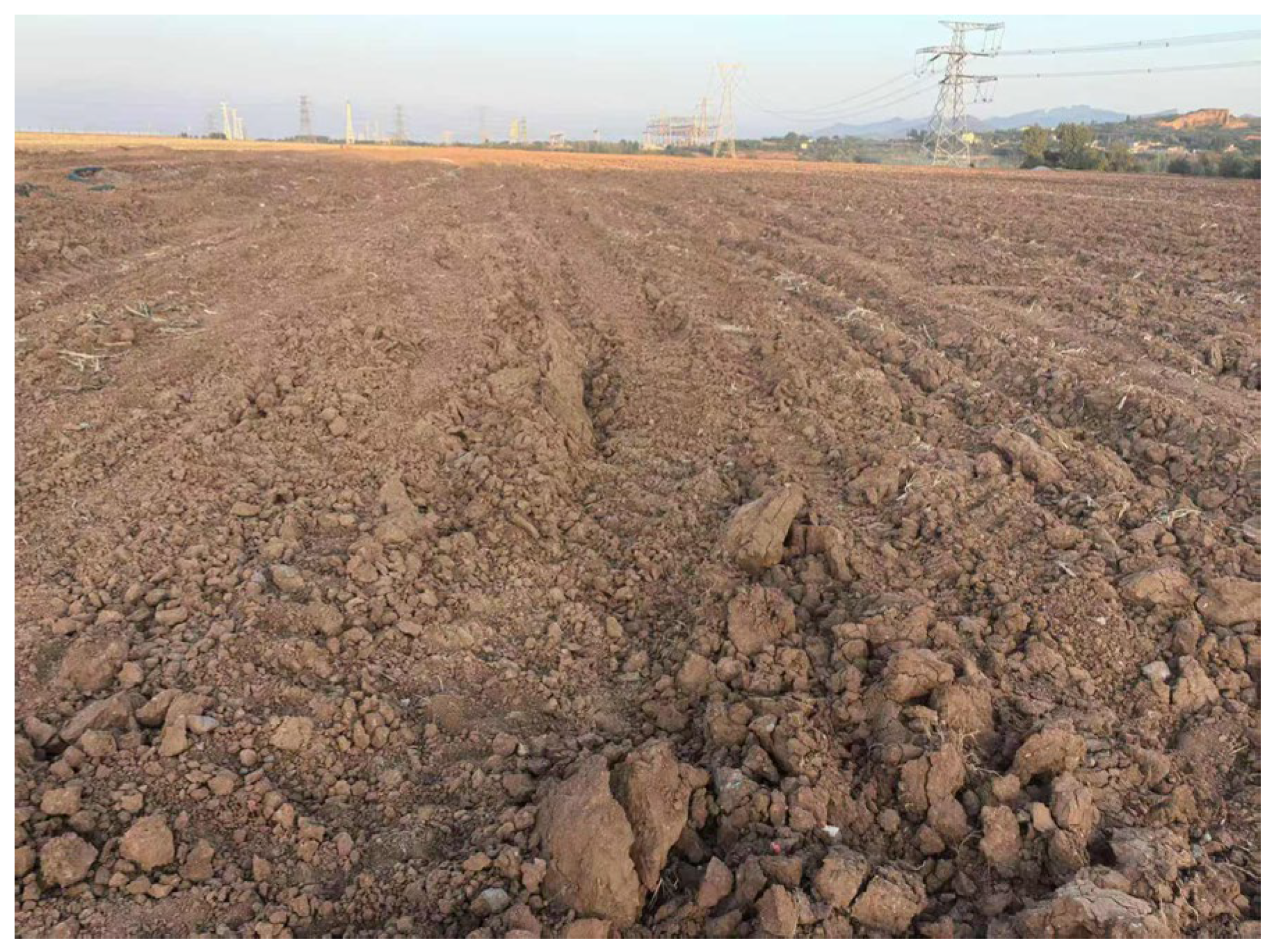
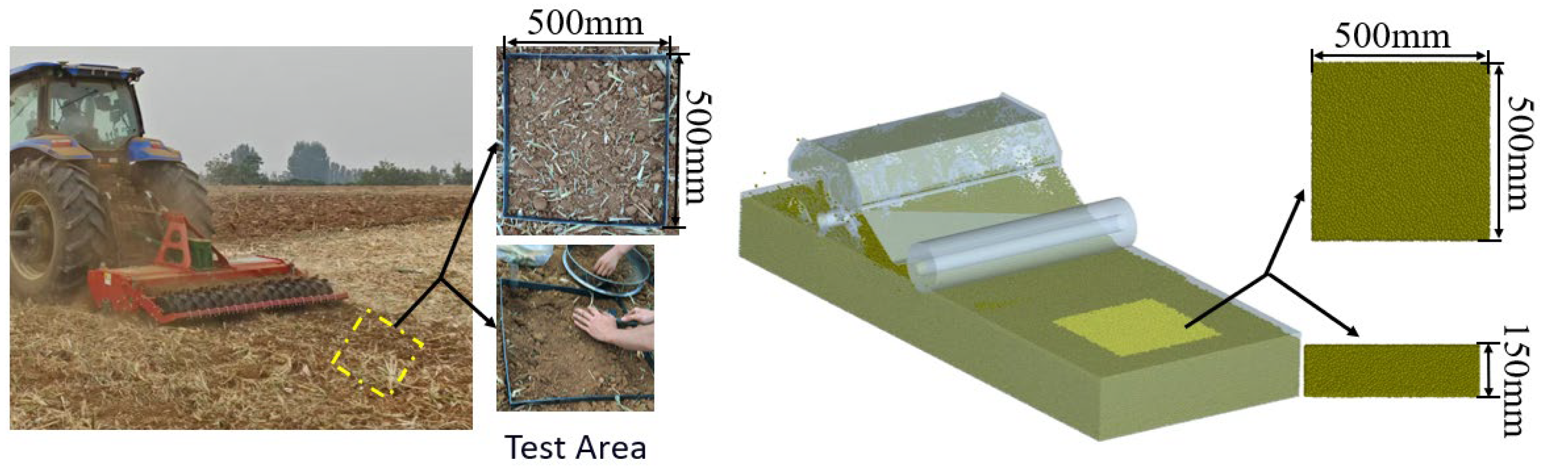
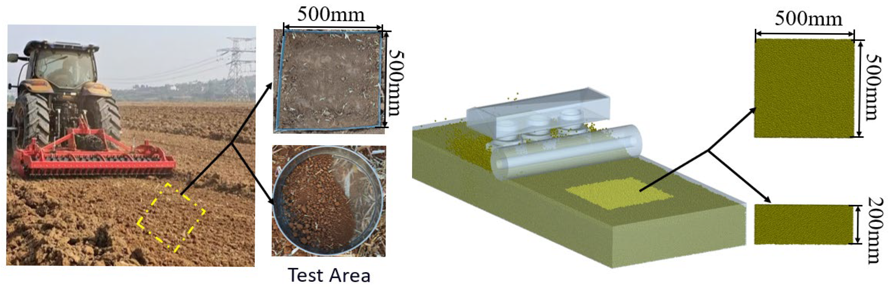
Funding

This research was funded by the Major Science and Technology Special Project of Henan Province, grant number 231100110200; the National Key R&D Program of China, grant number 2024YFB3714100; and the Science and Technology Research and Development Program Project of Henan Province, grant number 252102111182.

Institutional Review Board Statement

Not applicable.

Data Availability Statement

The data presented in this study are available upon request from the corresponding author. The data are not publicly available as they are part of ongoing research, and sharing them prematurely could compromise the results or findings.

Conflicts of Interest

The authors declare no conflicts of interest.

Abbreviations

The following abbreviations are used in this manuscript:
DEMDiscrete Element Method
AORAngle of repose
3DThree-dimensional
NSGA-IINon-dominated Sorting Genetic Algorithm II

References

  1. USS Working Group WRB. World Reference Base for Soil Resources 2014, Update 2015 International Soil Classification System for Naming Soils and Creating Legends for Soil Maps; World Soil Resources Reports No. 106; FAO: Rome, Italy, 2015. [Google Scholar]
  2. Shmulevich, I. State of the art modeling of soil–tillage interaction using discrete element method. Soil. Tillage Res. 2010, 111, 41–53. [Google Scholar] [CrossRef]
  3. Zhou, H.; Zhou, T.; Wang, X.; Hu, L.; Wang, S.; Luo, X.; Ji, J. Determination of Discrete Element Modelling Parameters of a Paddy Soil with a High Moisture Content (>40%). Agriculture 2022, 12, 2000. [Google Scholar] [CrossRef]
  4. Ucgul, M.; Fielke, J.M.; Saunders, C. Three-dimensional discrete element modelling (dem) of tillage: Accounting for soil cohesion and adhesion. Biosyst. Eng. 2015, 129, 298–306. [Google Scholar] [CrossRef]
  5. Li, S.; Hu, M.; Liu, Y.; Li, Y. Dem parameters of slope cultivated purple soil in southwest China and interaction mechanism between very narrow tine. Sci. Rep. 2024, 14, 18089. [Google Scholar] [CrossRef]
  6. Aikins, K.A.; Ucgul, M.; Barr, J.B.; Jensen, T.A.; Antille, D.L.; Desbiolles, J.M. Determination of discrete element model parameters for a cohesive soil and validation through narrow point opener performance analysis. Soil. Tillage Res. 2021, 213, 105123. [Google Scholar] [CrossRef]
  7. Xing, J.J.; Zhang, R.; Wu, P.; Zhang, X.R.; Dong, X.H.; Chen, Y.; Ru, S. Parameter Calibration of Discrete Element Simulation Model for Latosol Particles in Hot Areas of Hainan Province. Trans. Chin. Soc. Agric. Eng. 2020, 36, 158–166. [Google Scholar] [CrossRef]
  8. Yuan, N. Determination of soil field capacity by indoor ring-knife method. New Technol. New Prod. China 2014, 9, 184. [Google Scholar] [CrossRef]
  9. GB/T 5668-2017; Rotary Tiller, National Standard of The People’s Republic of China. Standardization Administration of the People’s Republic of China: Beijing, China, 2017.
  10. GB/T 25420-2021; Actuates the Raker, National Standard of The People’s Republic of China, Standardization Administration of the People’s Republic of China: Beijing, China, 2021.
  11. Al-Hashemi, H.M.B.; Al-Amoudi, O.S.B. A review on the angle of repose of granular materials. Powder Technol. 2018, 330, 397–417. [Google Scholar] [CrossRef]
  12. Bai, J.; Xie, B.; Yan, J.; Zheng, Y.; Liu, N.; Zhang, Q. Moisture content characterization method of wet particles of brown rice based on discrete element simulation. Powder Technol. 2023, 428, 118775. [Google Scholar] [CrossRef]
  13. Potyondy, D.O.; Cundall, P.A. A bonded-particle model for rock. Int. J. Rock. Mech. Min. Sci. 2004, 41, 1329–1364. [Google Scholar] [CrossRef]
  14. Aikins, K.A.; Ucgul, M.; Barr, J.B.; Awuah, E.; Antille, D.L.; Jensen, T.A.; Desbiolles, J.M.A. Review of Discrete Element Method Simulations of Soil Tillage and Furrow Opening. Agriculture 2023, 13, 541. [Google Scholar] [CrossRef]
  15. Fang, M.; Yu, Z.; Zhang, W.; Cao, J.; Liu, W. Friction coefficient calibration of corn stalk particle mixtures using Plackett-Burman design and response surface methodology. Powder Technol. 2022, 396, 731–742. [Google Scholar] [CrossRef]
  16. Yang, G.; Zhao, H.; Chen, Q.; Yu, X.; Li, Z.; Liu, K.; Zhang, M.; Liu, Z. Potassium chloride-modified urea phosphate with response surface optimization and its application effect on maize in saline-alkali soil. ACS Omega 2020, 5, 17255–17265. [Google Scholar] [CrossRef]
  17. Chen, G.; Wang, Q.; Li, H.; He, J.; Lu, C.; Sheng, S.; Zhang, X. Rapid acquisition method of discrete element parameters of granular manure and validation. Powder Technol. 2024, 431, 119071. [Google Scholar] [CrossRef]
  18. Wang, Z.; Zhu, T.; Wang, Y.; Ma, F.; Zhao, C.; Li, X. Optimal Discrete Element Parameters for Black Soil Based on Multi-Objective Total Evaluation Normalized-Response Surface Method. Processes 2023, 11, 2422. [Google Scholar] [CrossRef]
  19. Mudarisov, S.; Farkhutdinov, I.; Khamaletdinov, R.; Khasanov, E.; Mukhametdinov, A. Evaluation of the significance of the contact model particle parameters in the modelling of wet soils by the discrete element method. Soil. Tillage Res. 2022, 215, 105228. [Google Scholar] [CrossRef]
  20. Zhang, F.; Luo, Z.; Zheng, E.; Han, L.; Qian, J.; Yao, H.; Shi, Y.; Wang, X. Imitating pangolin scale structure for reducing adhesion and resistance of rotary tillage in wet-adhesive soil. Soil. Tillage Res. 2025, 245, 106306. [Google Scholar] [CrossRef]
  21. Du, J.; Heng, Y.; Zheng, K.; Luo, C.; Zhu, Y.; Zhang, J.; Xia, J. Investigation of the burial and mixing performance of a rotary tiller using discrete element method. Soil. Tillage Res. 2022, 220, 105349. [Google Scholar] [CrossRef]
  22. Jang, G.; Lee, S.; Lee, K.-J. Discrete element method for the characterization of soil properties in Plate-Sinkage tests. J. Mech. Sci. Technol. 2016, 30, 2743–2751. [Google Scholar] [CrossRef]
  23. Zhao, Z.; Hou, J.; Guo, P.; Xia, C.; Yan, H.; Wang, D. Analysis of Soil–Straw Movement Behavior in Saline–Alkali Soil Under Dual-Axis Rotary Tillage Based on EDEM. Agriculture 2025, 15, 337. [Google Scholar] [CrossRef]
  24. Zheng, S.; Lu, T.; Liu, J.; Tian, Y.; Han, M.; Tai, M.; Gao, S.; Liu, T.; Wang, D.; Zhao, Z. Discrete Element-Based Design of a High-Speed Rotary Tiller for Saline-Alkali Land and Verification of Optimal Tillage Parameters. Agriculture 2025, 15, 269. [Google Scholar] [CrossRef]
  25. Wu, Z.; Wang, X.; Liu, D.; Xie, F.; Ashwehmbom, L.G.; Zhang, Z.; Tang, Q. Calibration of discrete element parameters and experimental verification for modelling subsurface soils. Biosyst. Eng. 2021, 212, 215–227. [Google Scholar] [CrossRef]
  26. Liu, X.; Qi, H.; Wang, S.; Xu, Z.; Gao, P.; Fu, D.; Ma, Y. The Design and Experimentation of a Wing-Shaped Stubble-Breaking Device for Maize Stubbles. Agriculture 2024, 14, 2108. [Google Scholar] [CrossRef]
  27. Yang, Z.; Mo, Y.; Zhao, C.; Liu, H.; Zhang, Y.; Xiao, J.; Gong, S.; Bi, Y. Multi-Objective Optimization Design of the Small Flow Rate Emitter Structure Based on the NSGA-II Genetic Algorithm. Agriculture 2024, 14, 2336. [Google Scholar] [CrossRef]
  28. Liu, Z.; Ma, C.; Wei, X.; Xie, W. Experimental study on mechanical properties and failure modes of pre-existing cracks in sandstone during uniaxial tension/compression testing. Eng. Fract. Mech. 2021, 255, 107966. [Google Scholar] [CrossRef]
  29. Zhang, X.; Wang, H.; Wang, F.; Lian, Z. Parameter calibration of discrete element model for alfalfa seeds based on edem simulation experiments. Int. J. Agric. Biol. Eng. 2024, 17, 33–38. [Google Scholar] [CrossRef]
  30. Chen, S.; Chen, L.; Zhou, M.; Huang, J. Experimental investigation on factors influencing stable slope angle of granular accumulation. Appl. Mech. Mater. 2013, 438–439, 1238–1243. [Google Scholar] [CrossRef]
  31. Li, J.; Tong, J.; Hu, B.; Wang, H.; Ma, C.; Ma, Y. Calibration of parameters of interaction between clayey black soil with different moisture content and soil-engaging component in northeast China. Trans. CSAE 2019, 35, 130–140. [Google Scholar] [CrossRef]
  32. Shi, L.; Wu, J.; Zhao, W.; Sun, W.; Zhang, F.; Sun, B. Establishment and parameter verification of farmland soil model in uniaxial compression based on discrete element method. J. China Agric. Univ. 2015, 20, 174–182. [Google Scholar] [CrossRef]
  33. Li, Y.; Xu, Y. Comparison study between the soil uniaxial compression testand the discrete element simulation. J. China Agric. Univ. 2009, 14, 103–108. [Google Scholar] [CrossRef]
  34. Wankmüller, F.J.P.; Delval, L.; Lehmann, P.; Baur, M.J.; Cecere, A.; Wolf, S.; Or, D.; Javaux, M.; Carminati, A. Global influence of soil texture on ecosystemic water limitation. Nature 2024, 635, 631–638. [Google Scholar] [CrossRef] [PubMed]
  35. Yu, L.; Tian, R.; Zhang, R.; Liu, X.; Li, R.; Li, H. Coupling effects of humus and 2:1 type electrolyte on soil water movement. Geoderma 2020, 375, 114482. [Google Scholar] [CrossRef]
  36. Wang, F.; Zeng, Y.; Zhang, Z.; Xie, K.; Li, D.; He, Z. Parameter calibration of discrete element simulation model for Panax notoginseng planting soil. J. South. China Agric. Univ. 2024, 45, 588–597. [Google Scholar] [CrossRef]
  37. Wang, D.; Lu, T.; Zhao, Z.; Shang, S.; Zheng, S.; Liu, J. Calibration of Discrete Element Simulation Parameters for Cultivated Soil Layer in Coastal Saline-Alkali Soil. Trans. Chin. Soc. Agric. Mach. 2024, 55, 240–249. [Google Scholar] [CrossRef]
Figure 1. Yellow cinnamon soil experimental field.
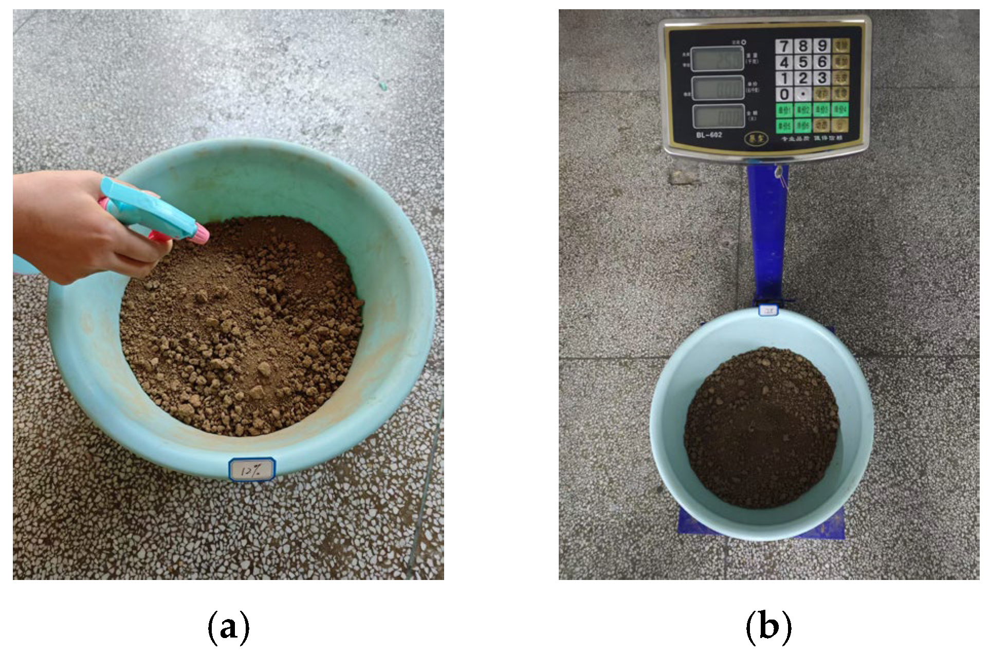
Agriculture 15 01365 g001
Figure 2. The soil moisture content ratioing process. (a) Soil moisture content calibration process. (b) Soil mass determination.
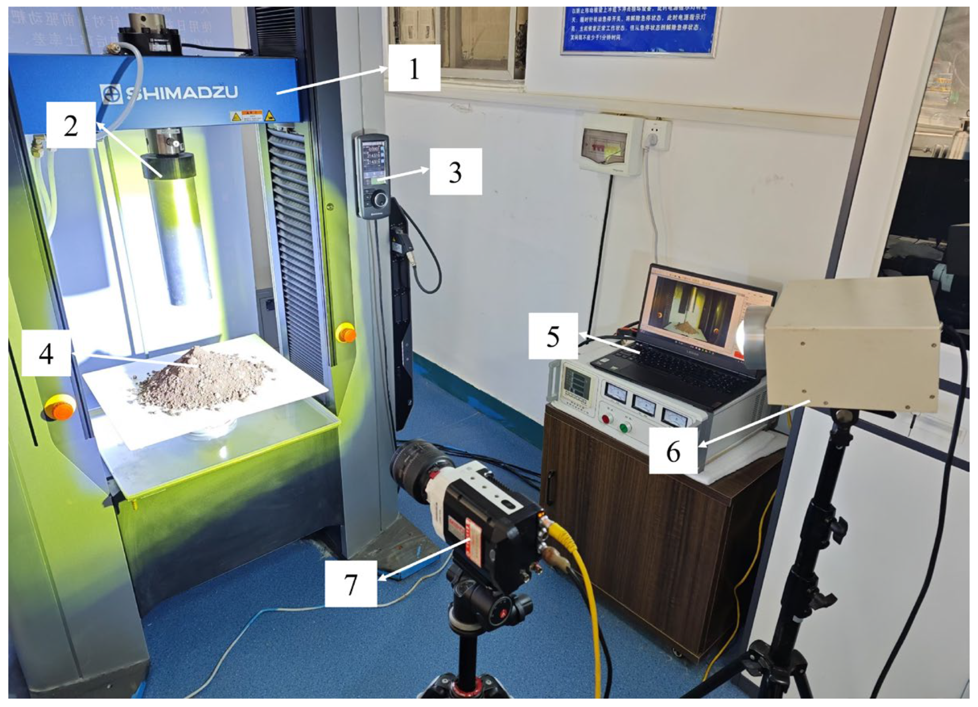
Agriculture 15 01365 g002
Figure 3. Cylindrical lifting test device. 1—Universal testing machine; 2—test cylinder; 3—control unit; 4—experimental soil specimen; 5—image acquisition interface; 6—ring light; 7—high-speed imaging system.
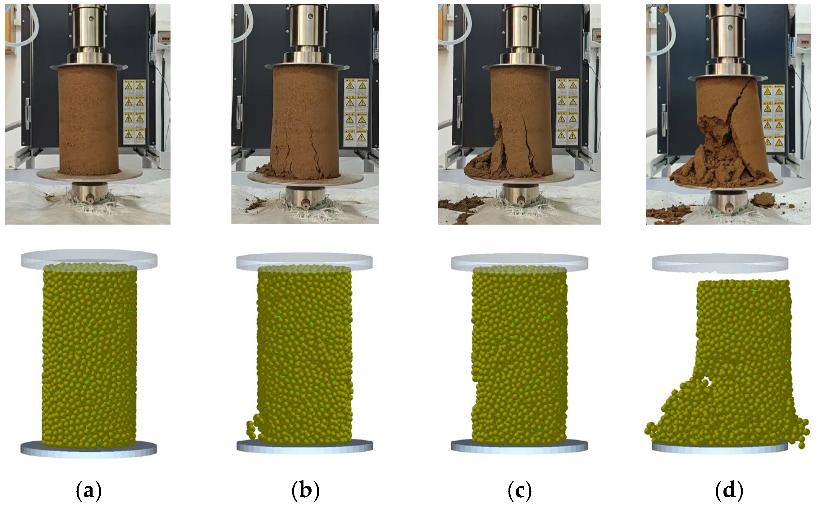
Agriculture 15 01365 g003
Figure 4. Uniaxial compression physical test soil collapse. Phases: 1—Universal testing machine; 2—plexiglass cylinder; 3—clamp collar; 4—force and displacement transducer; 5—compression platen; 6—caked soil. (a) Soil compaction phase. (b) Soil crushing phase.
Agriculture 15 01365 g004
Figure 5. Soil angle of repose at different moisture contents: (a) 4%, (b) 8%, (c) 12%, (d) 16%, (e) 20%, and (f) 24%.
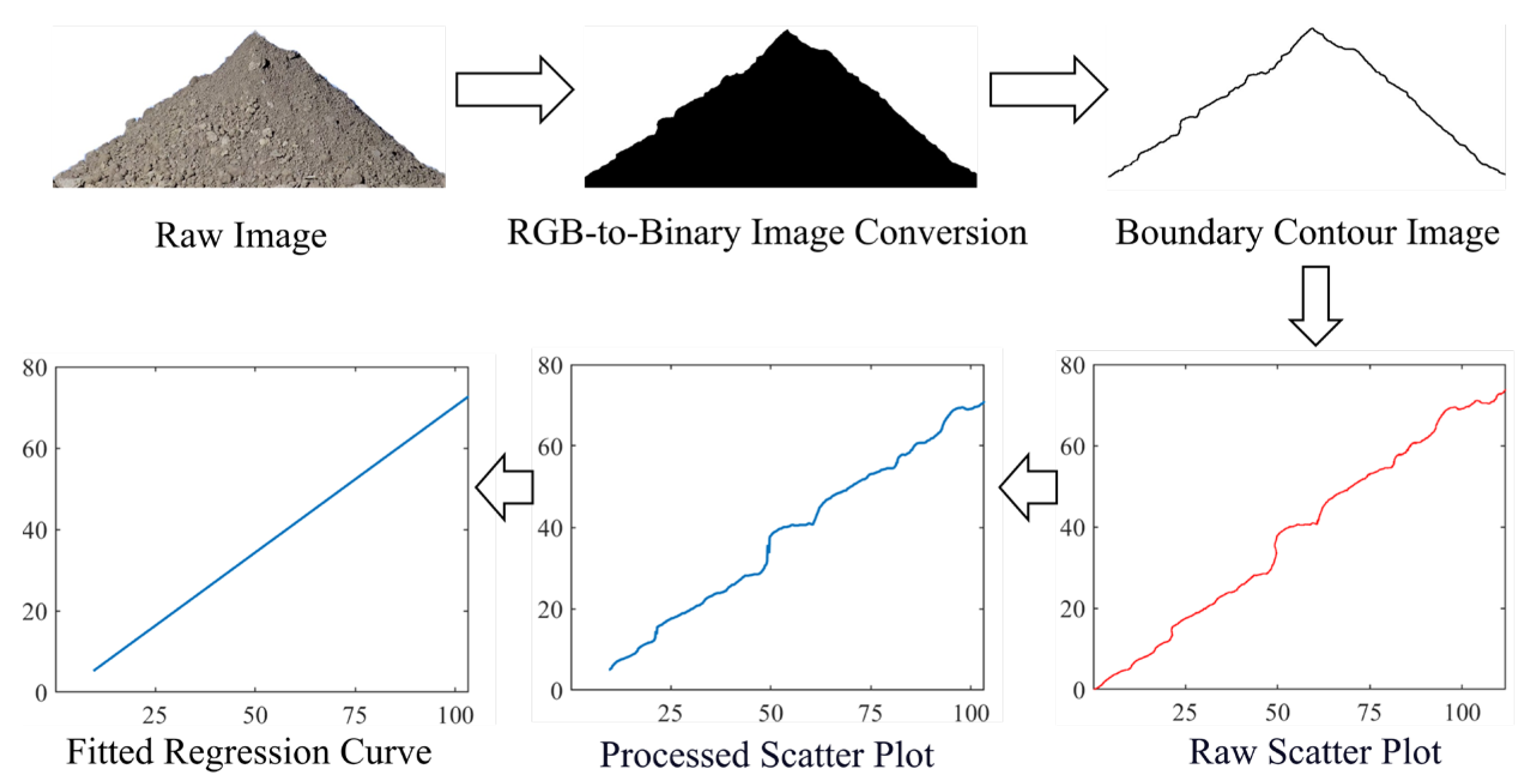
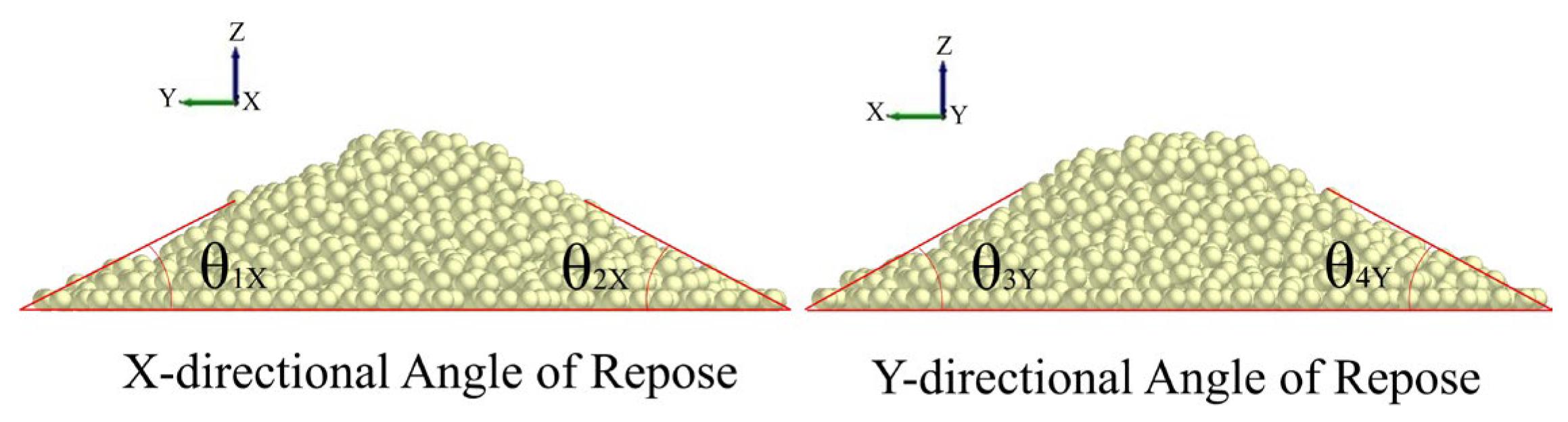
Agriculture 15 01365 g005
Figure 6. The process of acquiring images for angle of repose measurement.
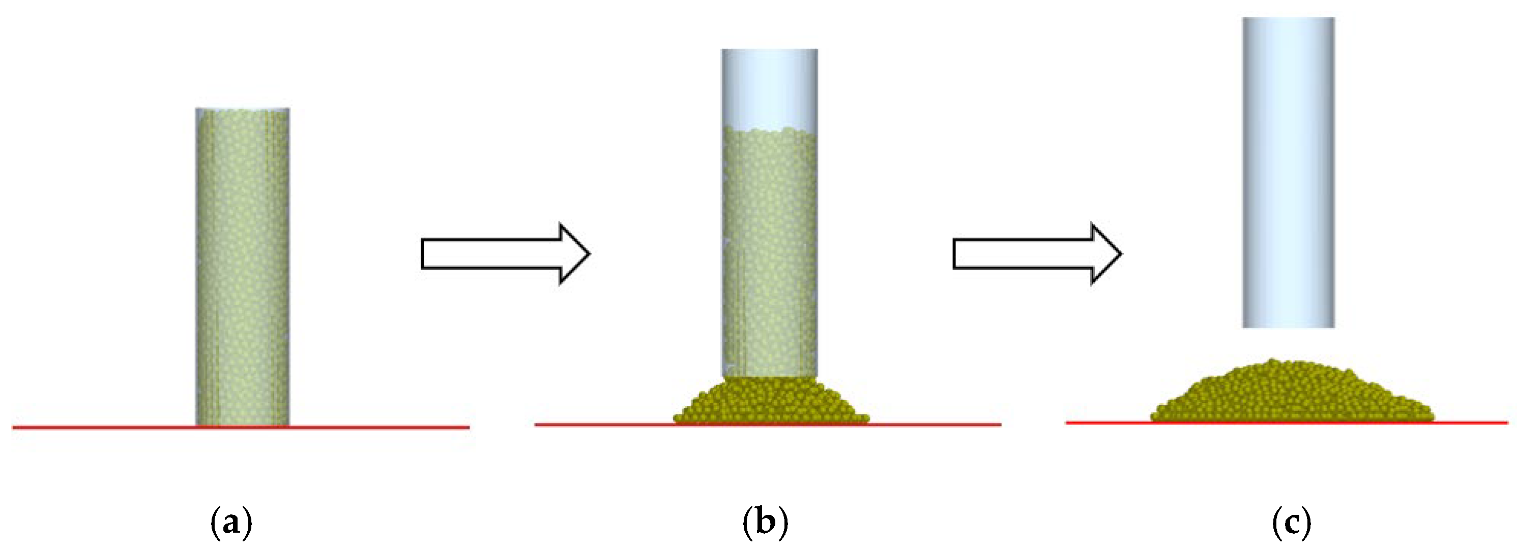
Agriculture 15 01365 g006
Figure 7. Angle of repose formation process. (a) Initiation of elevation process. (b) Elevation in progress. (c) Completion of elevation sequence.
Agriculture 15 01365 g007
Figure 8. Simulation test of soil angle of repose measurement.
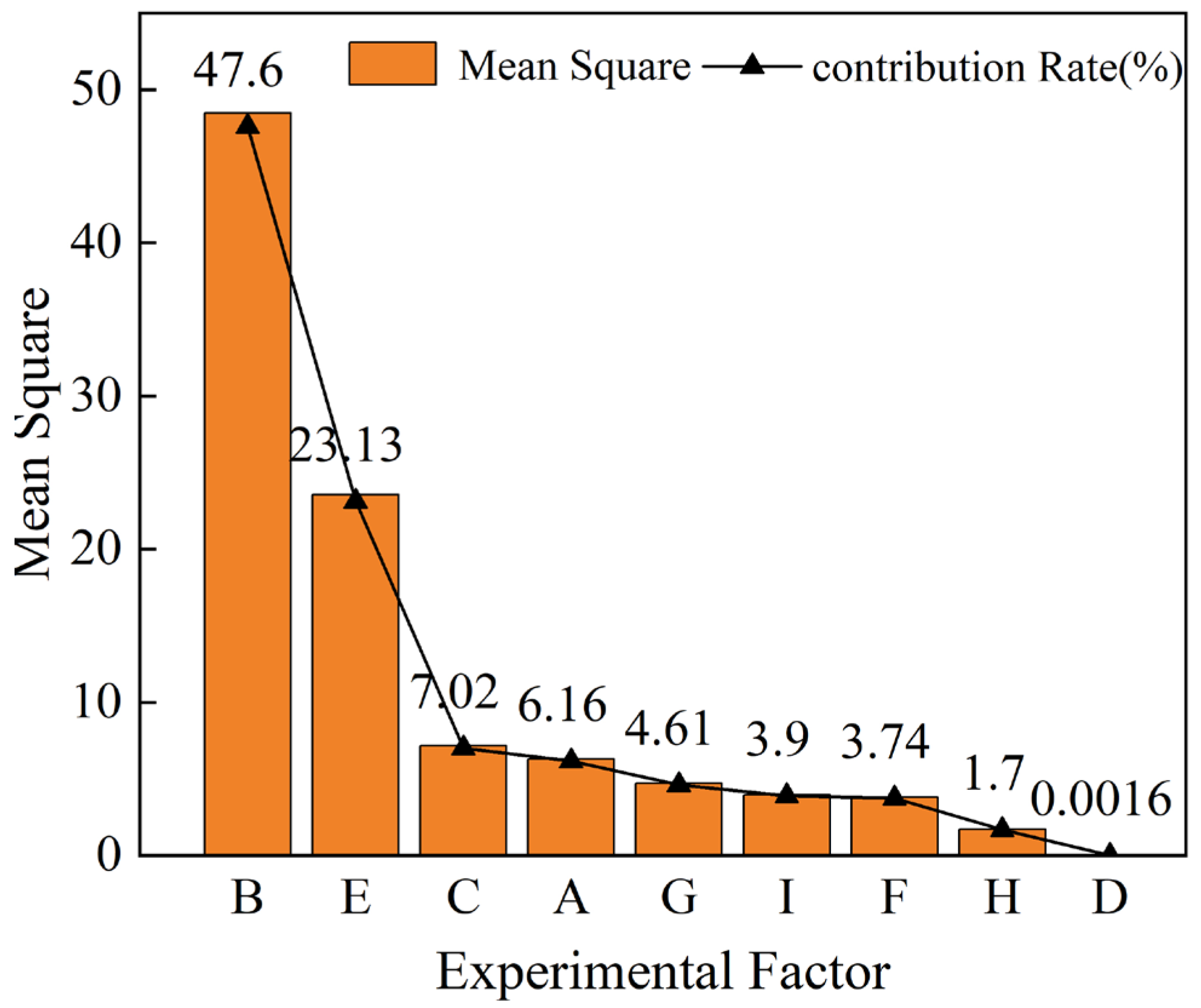
Agriculture 15 01365 g008
Figure 9. Pareto graph of experimental results.
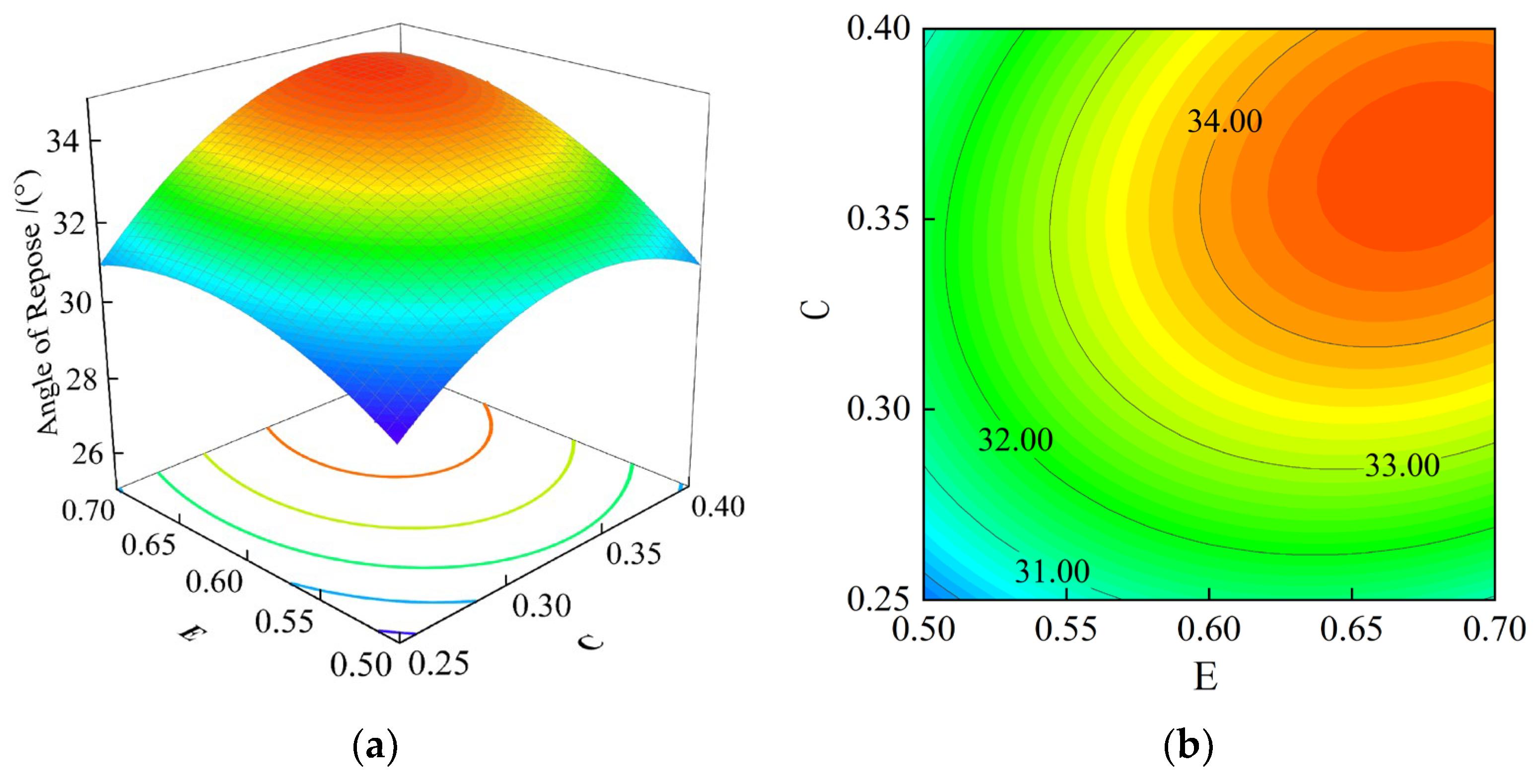
Agriculture 15 01365 g009
Figure 10. The influence of interaction parameters on soil accumulation angle. (a) Three-dimensional response surface (EC). (b) Contour plot (EC). The blue, green, yellow, and red colors in the figure sequentially represent the increasing trend of accumulation angle from minimum to maximum values.
Agriculture 15 01365 g010
Figure 11. Comparison of angle of repose between physical and simulation tests. (a) 4%. (b) 8%. (c) 12%. (d) 16%. (e) 20%. (f) 24%.
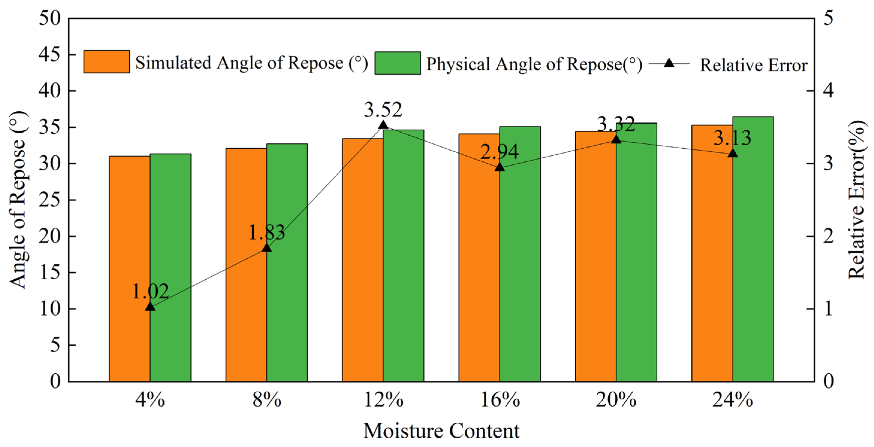
Agriculture 15 01365 g011
Figure 12. Physical experiment and simulation experiment: angle of repose error analysis.
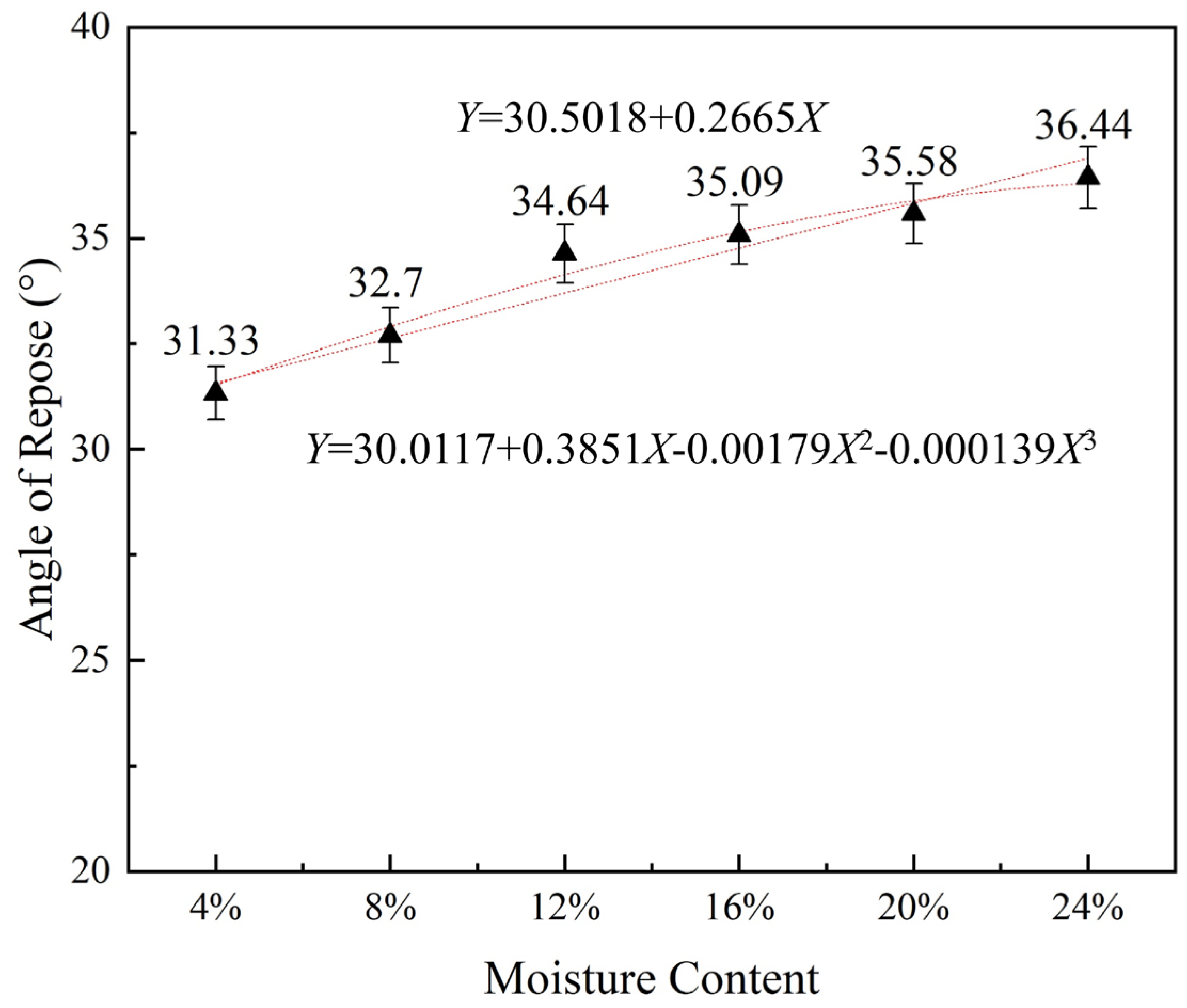
Agriculture 15 01365 g012
Figure 13. Soil moisture content and angle of repose relationship curve.
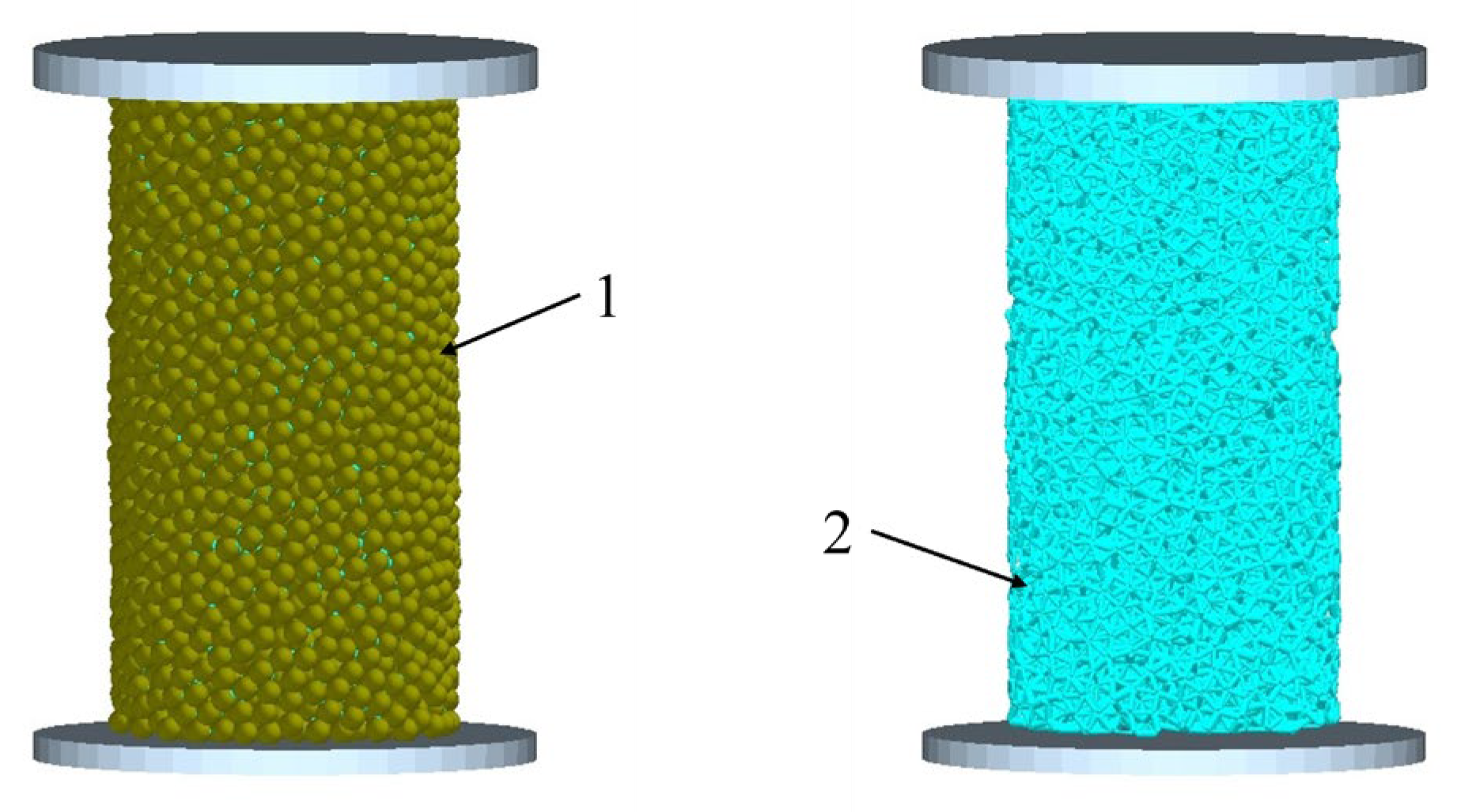
Agriculture 15 01365 g013
Figure 14. Uniaxial compression simulation test. 1—Soil block model; 2—interparticle bond.
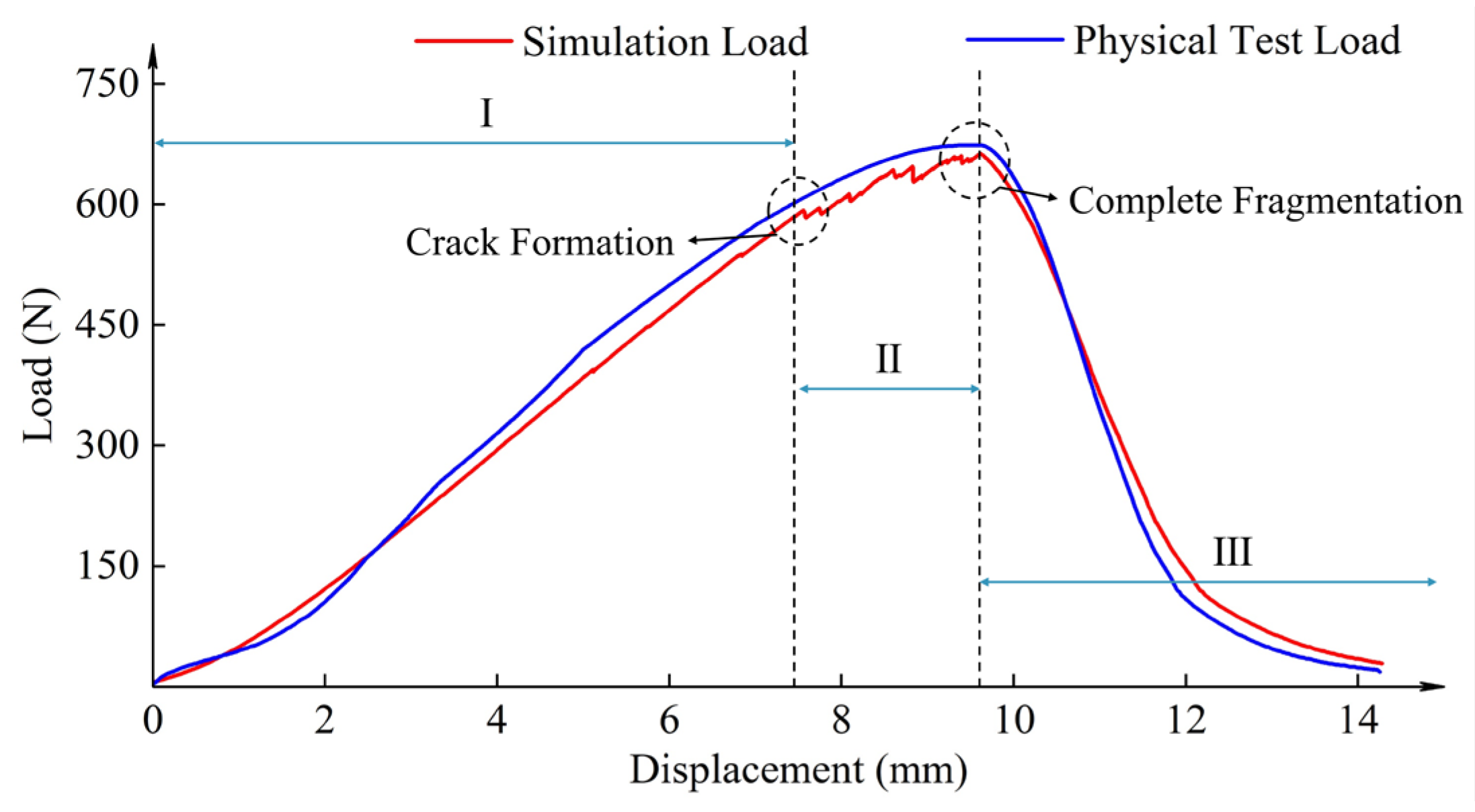
Agriculture 15 01365 g014
Figure 15. Comparison of displacement–load variations between uniaxial compression simulation tests and physical experiments.
Agriculture 15 01365 g015
Figure 16. Compressive deformation comparison. (a) Compression initiation. (b) Crack initiation. (c) Ultimate load. (d) Complete crushing.
Agriculture 15 01365 g016
Figure 17. Comparison chart of rotary tiller field test and simulation experiments.
Agriculture 15 01365 g017
Figure 18. Comparison chart of power-driven harrow field experiment and simulation experiments.
Agriculture 15 01365 g018
Table 1. Physical angle of repose test results.
Moisture ContentAngle of Repose (°)
12345Average
0%33.332.933.832.726.630.12
4%32.531.133.332.831.531.33
8%31.533.23330.535.232.7
12%35.7535.235.532.434.934.64
16%35.5335.134.8336.836.0535.09
20%35.733.233.434.235.235.58
24%33.133.93534.436.736.44
Table 2. Plackett–Burman test parameters.
Symbol Parameter Unit Factor Level
Level −1 Level +1
ACoefficient of restitution between soil particles/0.10.6
BCoefficient of the static friction between soil particles/0.30.7
CCoefficient of rolling friction between soil particles/0.10.4
DCoefficient of restitution between soil particles and 65Mn/0.160.6
ECoefficient of static friction between soil particles and 65Mn/0.30.7
FCoefficient of rolling friction between soil particles and 65Mn/0.010.4
GSoil particle Poisson’s ratio/0.250.4
HSoil particle shear modulusMPa12.99
ISoil particle densitykg·m−312002680
Table 3. Plackett–Burman experimental protocol and results.
No.ABCDEFGHIAngle of Repose (°)
111−1111−1−1−129.10
2−111−1111−1−130.10
31−111−1111−125.55
4−11−111−111127.09
5−1−11−111−11124.85
6−1−1−11−111−1120.96
71−1−1−11−111−125.97
811−1−1−11−11125.60
9111−1−1−11−1126.80
10−1111−1−1−11−126.85
111−1111−1−1−1123.80
12−1−1−1−1−1−1−1−1−119.70
Table 4. Plackett–Burman analysis of test results.
ParameterMean Sum of SquaresContribution Rate (%)p-ValuePriority Ranking
A4.404.500.0624 *5
B50.8851.950.0059 ***1
C7.577.730.0378 **3
D0.00910.0090.87859
E19.8920.310.0149 **2
F2.953.010.0892 *7
G3.603.670.0749 *6
H2.482.530.10378
I5.565.680.0504 *4
Note: An asterisk (*) indicates marginal significance (0.05 < p < 0.1); a double asterisk (**) indicates statistical significance (0.01< p < 0.05); and a triple asterisk (***) indicates high statistical significance (p < 0.01).
Table 5. Design and results of steepest ascent experiment.
No.Coefficient of Static Friction between Soil Particles (B)Coefficient of Static Friction Between Soil Particles and 65Mn (E)Coefficient of Rolling Friction Between Soil Particles (C)Angle of Repose (°)
10.30.30.121.80
20.40.40.17526.08
30.50.50.2532.03
40.60.60.32534.60
50.70.70.435.90
Table 6. Box–Behnken experimental factors and levels.
CodingParameters
BEC
+10.50.50.25
00.60.60.325
−10.70.70.4
Table 7. Box–Behnken experimental design plan and results.
No.Factor LevelsAngle of Repose (°)
BEC
10.50.60.2528.1
20.70.60.2533.15
30.50.60.430.9
40.70.60.434.3
50.50.50.32529.3
60.70.50.32532.8
70.50.70.32531.3
80.70.70.32535.4
90.60.50.2529.26
100.60.50.431.2
110.60.70.2530.68
120.60.70.434.4
130.60.60.32534.42
140.60.60.32533.62
150.60.60.32533.8
160.60.60.32533.5
Table 8. Pile angle regression model analysis of variance.
Source of VarianceSum of SquaresDegree of FreedomMean SquareF-Valuep-Value
Model67.1197.4644.89<0.0001 ***significant
B30.62130.62184.31<0.0001 ***
C9.8319.8359.210.0003 ***
E10.76110.7664.810.0002 ***
BE0.390610.39062.350.1760
BC0.160010.16000.96330.3643
EC1.1211.126.760.0406 *
B22.0812.0812.530.0122 **
E28.4218.4250.720.0004 ***
C23.7213.7222.370.0032 ***
Residual0.996660.1661
Lack of fit0.494730.16490.98570.5046not significant
Pure error0.501930.1673
Sum68.1115
Note: An asterisk (*) indicates marginal significance (0.05 < p < 0.1); a double asterisk (**) indicates statistical significance (0.01 < p < 0.05); and a triple asterisk (***) indicates high statistical significance (p < 0.01).
Table 9. Simulation experiment and physical experiment error analysis results.
Moisture
Content
BECSimulated Angle of Repose (°)Physical Angle of Repose (°)Relative
Error
4%0.5020.6020.33831.0131.331.02%
8%0.6380.5870.26732.1032.71.83%
12%0.6730.6260.333.4234.643.52%
16%0.6360.6830.35934.0635.092.94%
20%0.6880.6830.33734.4035.583.32%
24%0.70.6880.34935.3036.443.13%
Table 10. Optimal parameters for soil simulation with the actual moisture content.
Moisture Content (%)ParametersSimulated Angle of Repose (°)
BEC
17.30.60.690.35834.84
Table 11. Calibration range of bonding parameters for soil blocks.
LevelNormal Stiffness per Unit Area A (×107 N·m−3)Shear Stiffness per Unit Area B (×107 N·m−3)Critical Normal Stress C (×104 Pa)Critical Shear Stress D (×104 Pa)Bonded Disk Radius E (mm)
17752.74.8
287.563.45
39874.15.2
4108.584.85.4
Table 12. Calibration test scheme and results for soil blocks.
No.ABCDELoad (N)Displacement (mm)
17752.74.8182.819.08
277.563.45578.389.57
37874.15.2858.2012.32
478.584.85.4234.595.94
58764.15.4965.8911.07
687.554.85.21269.1314.29
78882.75152.936.71
888.573.44.81127.9512.48
99774.851279.1514.48
1097.584.14.8947.0011.66
119853.45.4564.718.48
1298.562.75.2152.195.04
1310783.45.2845.8310.26
14107.572.75.4454.015.98
1510864.84.81110.9312.71
16108.554.15809.059.52
Table 13. Variance analysis of the soil block calibration test results.
SourceSource of VariationDegree of FreedomSum of SquaresMean SquareF-Valuep-Value
DisplacementRegression595.007319.0025.010.015 **
Error1037.94363.794
Total15132.9508
LoadRegression51,522,849.65304,569.93.590.041 **
Error10848,541.8784,854.19
Total152,371,391.52
Note: An asterisk (*) indicates marginal significance (0.05 < p < 0.1); a double asterisk (**) indicates statistical significance (0.01 < p < 0.05); and a triple asterisk (***) indicates high statistical significance (p < 0.01).
Table 14. Critical bonding parameters of the soil.
ModelBonding ParameterData
Hertz–Mindlin with bondingNormal stiffness per unit area/×107 N·m−38.8
Tangential stiffness per unit area/×107 N·m−36.85
Critical normal stress/×104 Pa6
Critical shear stress/×104 Pa3.15
Bond radius/mm5.2
Table 15. Critical contact parameters of the soil.
ParameterData
The coefficient of restitution between soil particles0.35
Coefficient of the static friction between soil particles0.6
Coefficient of rolling friction between soil particles0.358
Coefficient of restitution between soil particles and 65Mn0.38
Coefficient of static friction between soil particles and 65Mn0.69
Coefficient of rolling friction between soil particles and 65Mn0.205
Soil particle Poisson’s ratio0.325
Soil particle shear modulus1.995
Soil particle density1940
Disclaimer/Publisher’s Note: The statements, opinions and data contained in all publications are solely those of the individual author(s) and contributor(s) and not of MDPI and/or the editor(s). MDPI and/or the editor(s) disclaim responsibility for any injury to people or property resulting from any ideas, methods, instructions or products referred to in the content.

