Article

Parameter Optimization Design and Experimental Validation of a Header for Electric Rice Reaper Binders Employed in Hilly Regions

1
College of Mechanical and Electrical Engineering, Fujian Agriculture and Forestry University, Fuzhou 350002, China
2
Fujian University Engineering Research Center for Modern Agricultural Equipment, Fujian Agriculture and Forestry University, Fuzhou 350002, China
*
Authors to whom correspondence should be addressed.
Agriculture 2025, 15(12), 1242; https://doi.org/10.3390/agriculture15121242
Submission received: 6 May 2025 / Revised: 29 May 2025 / Accepted: 5 June 2025 / Published: 6 June 2025
(This article belongs to the Section Agricultural Technology)

Abstract

The operation of electric rice reaper binders in hilly and mountainous areas currently faces the challenges of poor conveying efficiency and high harvest losses caused by the large dispersion of rice stem posture angles. In this study, we propose a multiparameter collaborative optimization method for improving header structure in an effort to address these challenges. First, key parameters influencing lifting performance and their operational ranges were determined based on a theoretical analysis of the stem-lifting mechanism’s kinematic characteristics. A dynamic model simulating the header’s lifting process was developed by using the ADAMS multibody dynamics platform. Subsequently, we designed a quadratic regression orthogonal rotation combination experiment with three factors, i.e., the stem-lifting speed ratio coefficient, the cutter installation position, and the header tilt angle, using the stem-lifting angle as the evaluation metric. The variance in the experimental data was analyzed with Design-Expert 13.0, and response surface methodology (RSM) was applied to elucidate the parameter interaction effects. The optimal parameter combination was identified as a speed ratio coefficient of 2.14, a cutter installation position of 258.79 mm, and a header tilt angle of 62.63°, yielding a theoretical stem-lifting angle of 2.36°. Field validation tests demonstrated an actual stem-lifting angle of 2.44° (relative error: 3.39%) and a header loss rate of 0.59%, representing a 49.6% reduction compared with the pre-optimized design. These results confirm that the optimized header satisfies operational requirements for hilly terrain rice harvesting, providing both theoretical guidance and technical advancements for the design of low-loss harvesting machinery.

1. Introduction

Rice serves as a staple food for over 50% of the global population, which underscores its strategic significance in ensuring food security [1]. While large-scale mechanized harvesting has been widely adopted in plains, hilly and mountainous regions—such as Southeast Asia—face persistent challenges due to fragmented fields and complex terrain. These constraints severely limit the deployment of medium- and large-scale harvesting machinery, rendering conventional large-area operational strategies impractical. Recent advancements in small-scale agricultural machinery have spurred progress in compact rice harvesters tailored for hilly terrains. As the core functional unit of such equipment, the header coordinates critical processes, including stem lifting, cutting, and conveying. The compatibility between its structural configuration and operational parameters directly governs harvesting quality, as mismatches can induce elevated missed-cutting rates and substantial grain losses. Consequently, the development of low-loss, high-efficiency headers is imperative for enhancing mechanized harvesting capabilities and ensure food security in these regions.
The contact between the stem and the stem-lifter mechanism’s lifting fingers involves friction and slip, constituting a nonlinear collision process. Traditional analytical methods struggle to accurately compute the transient variations in contact forces. The Contact module in ADAMS can simulate this contact behavior by configuring a nonlinear stiffness model. However, adjusting a single parameter of the header may trigger cascading effects on the overall operational state and structural dynamics. Multibody simulation enables the capture of cross-component dynamic transmission characteristics, facilitates the modeling of diverse working conditions, and circumvents the “trial-and-error” limitations inherent in conventional testing approaches.
Globally, headers for large- and medium-scale harvesters have benefited from extensive research and technical refinement. For instance, the C230 header developed by John Deere [2] integrates mature separation mechanisms and Crop Tracking System (CTS) technology, enabling efficient multi-crop harvesting with minimal losses. Similarly, the CLAAS VARIO header [3], designed for grain and rapeseed harvesting, achieves superior operational performance and high output, and adjusting its baseplate alignment under varying field conditions can increase overall machine efficiency by up to 10%. Case IH’s HDX- 2 sickle-bar header [4] employs dual sickle blades with recoil action for clean cutting and offers three adjustable cutting widths to accommodate diverse harvesting requirements. In parallel, researchers have focused on optimizing header dynamics. Li, Y. et al. [5] reduced frame vibrations by analyzing modal frequencies and vibration patterns, while Slaughter, D.C. et al. [6] identified counterbalance mass and positioning as critical factors influencing vibrational stability. Takashi, F [7] further advanced this understanding by modeling cutter drive system dynamics, demonstrating that counterbalance mass selection is independent of clearance between moving blades and connecting rods. Research studies on small-scale crop harvesting machinery (such as rice reaper binders, whose working process is shown in Figure 1) include the following: Cao, Z. et al. [8] addressed the poor adaptability and high harvesting loss rates in soybean–maize strip intercropping scenarios by designing a novel header based on multi-objective optimization and lightweight design methods. This header significantly reduced loss rates and achieved a weight reduction of 28.4 kg, improving the quality and efficiency of mechanized harvesting in strip intercropping systems. Shi, R. et al. [9] employed MBD-DEM combined simulation technology to analyze the causes of header entanglement and proposed an anti-entanglement device design. Field verification tests showed a total loss rate of 2.29%, with significantly improved operational efficiency. Liu, Y. et al. [10] designed a clamping and conveying device for headers to solve seed spattering during harvesting, constructing a test bench to conduct quadratic regression orthogonal rotation tests. Verification and comparative tests under optimal structural parameters demonstrated that this device significantly reduced sunflower seed loss rates. Liang, S. et al. [11] developed the 4LZG-3.0 millet combine harvester to address the challenges of difficult mechanized harvesting and high losses, effectively reducing header losses and significantly minimizing threshing and cleaning losses. Niu, Y. et al. [12] proposed a new profiling control strategy to solve the limitation of existing systems that they can only be adjusted vertically (they do not allow for the control of horizontal and cutting angles), verifying the system’s accuracy and stability with software simulation and field tests. Luo, Y. et al. [13] designed a 2-DOF adaptive header for forage harvesters, using fuzzy PID control to achieve the precise regulation of height (error ≤ 7.5 mm) and inclination (error ≤ 0.57°). Combined simulation and field validation showed strong system stability, meeting all-terrain operational requirements. Tan, H. et al. [14] developed an adaptive height adjustment system based on pressure wheel profiling and PID control to address low manual control accuracy in corn header systems. Tests showed that when the system was activated, the header height error decreased significantly, with both the coefficient of variation and the ear loss rate being reduced substantially. Qiu, S. et al. [15] developed a dual-chain millet (it can feed double rows of millet stems simultaneously) header based on contact mechanics principles, achieving significant loss reduction in field trials. Bawatharani, R. et al. [16] quantified the effects of cutting height and forward speed on grain loss and rice quality, whereas Zareei, S. et al. [17] identified forward speed as the dominant factor affecting header losses through multi-factorial experimentation. Tian, Y. et al. [18] redesigned the spiral conveyor and feeding chamber of a legacy pull-type harvester, significantly improving conveying efficiency and small-grain harvesting capacity. Liu, W. et al. [19] further reduced impurity and loss rates by introducing a spiral stepped cleaning device for headers. Wang, G. et al. [20] aimed to address the high failure rate of combine harvesters in China; thus, a load test system was developed, and field load tests were conducted. The results indicated that increased operating speeds and stubble heights led to elevated power consumption across components, with particularly significant power demands being observed in the chassis half-shafts. The average power consumption of the intermediate shaft reached 34.03 kW. 21. Qing, Y. et al. [21], designed a self-cleaning device for the harvester header by implementing optimization based on orthogonal combination experiments. Experimental results demonstrated a self-cleaning rate of 97.68%, providing theoretical guidance for the design and optimization of self-cleaning headers in rice production. Liu, W. et al. [22] designed a profiling header allowing for the adaptive adjustment of its height and levelness based on the theoretical analysis of the profiling mechanism and by employing a multi-objective optimization method. Bench tests demonstrated high ground profiling accuracy and confirmed the rationality of the structural design. Collectively, these studies focus on hotspots including multi-crop header design, improvement in component performance, intelligent header design, slope header design, and loss reduction technologies.
Despite these advancements, critical gaps persist in the dynamic parameter matching of stem-lifting mechanisms, particularly for headers in small electric rice reaper binders (where small devices are 2000 mm in length, 850 mm in width, and 800 mm in height). Such headers rely on synchronized interactions among stem-lifting devices, cutters, and conveying chains. The stem-lifting angle (γ)—defined as the posture angle of rice stems when they are supported by the stem-lifting mechanism at the cutting instant—critically influences conveying quality and loss rates. However, existing designs for small electric reaper binders often exhibit parameter mismatches among actuators, leading to stem collapse, missed cutting, and elevated losses. In this study, we establish a dynamic model of the stem-lifting process by using ADAMS software to address this limitation. A Box–Behnken experimental design is employed to analyze interactions among key operational parameters, enabling the identification of optimal parameter combinations. Field validation confirms the efficacy of the optimized header, providing a novel technical solution to enhance the harvesting performance of rice reaper binders employed on hilly terrains.

2. Materials and Methods

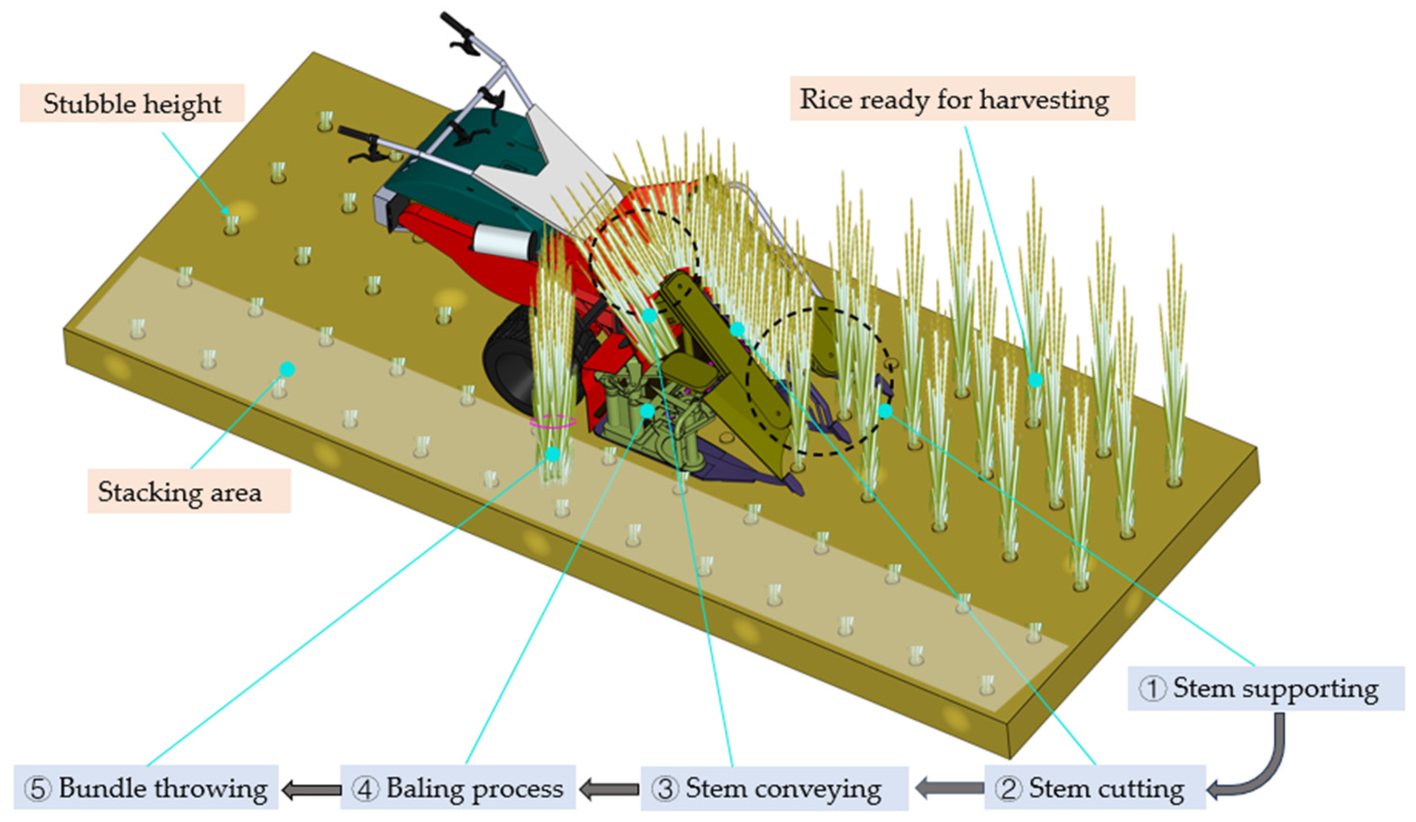
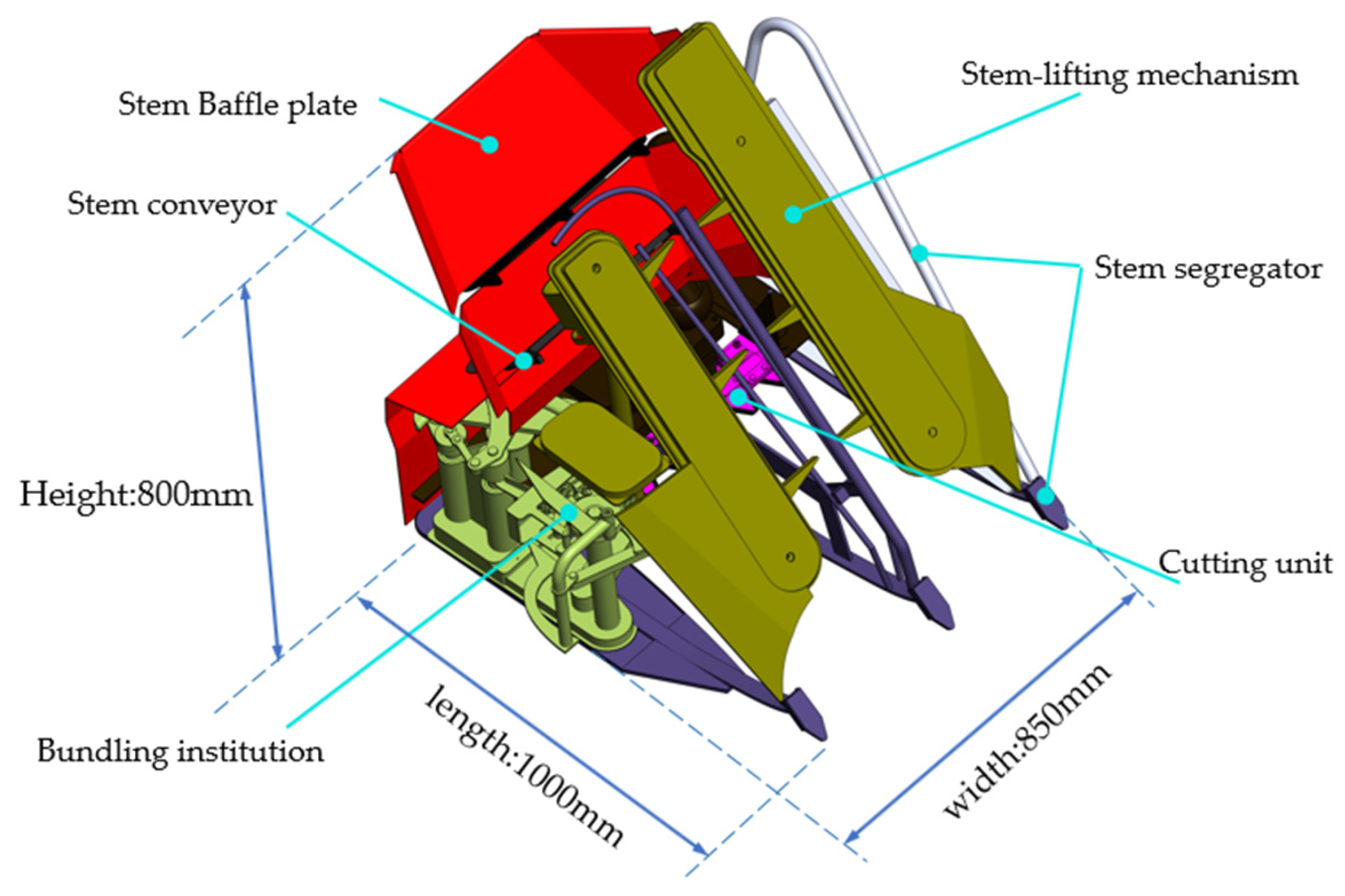
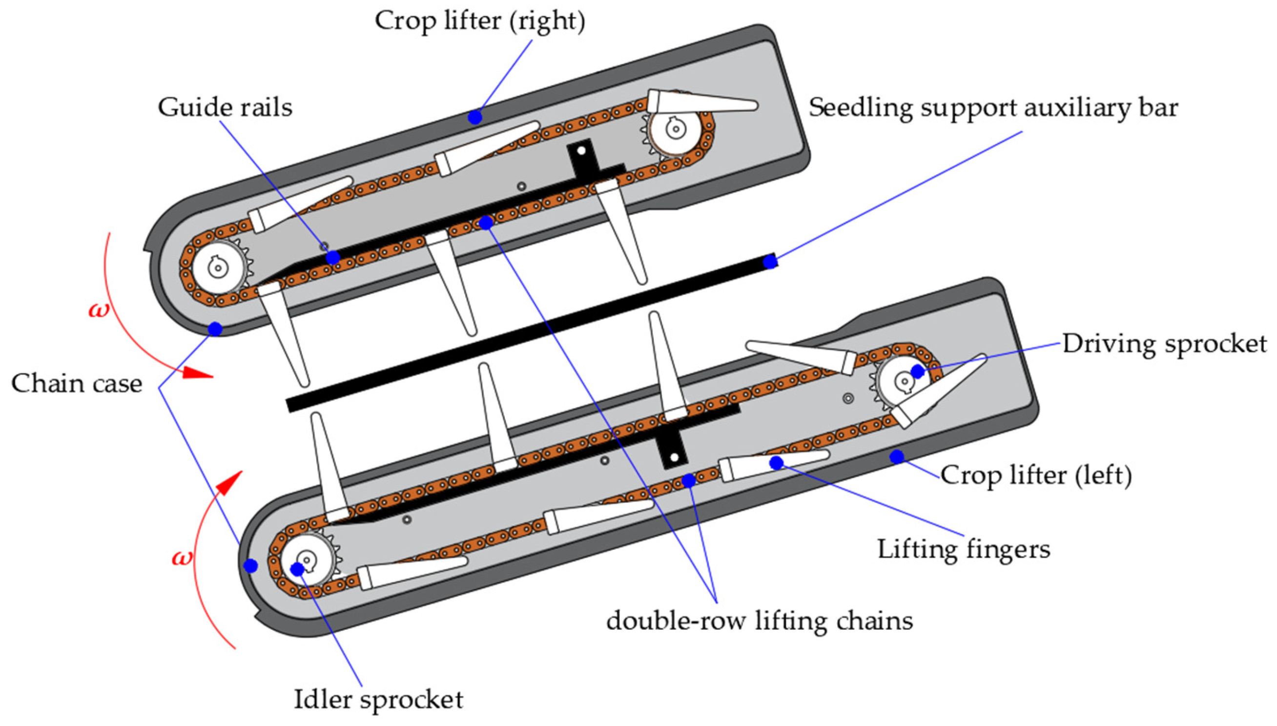
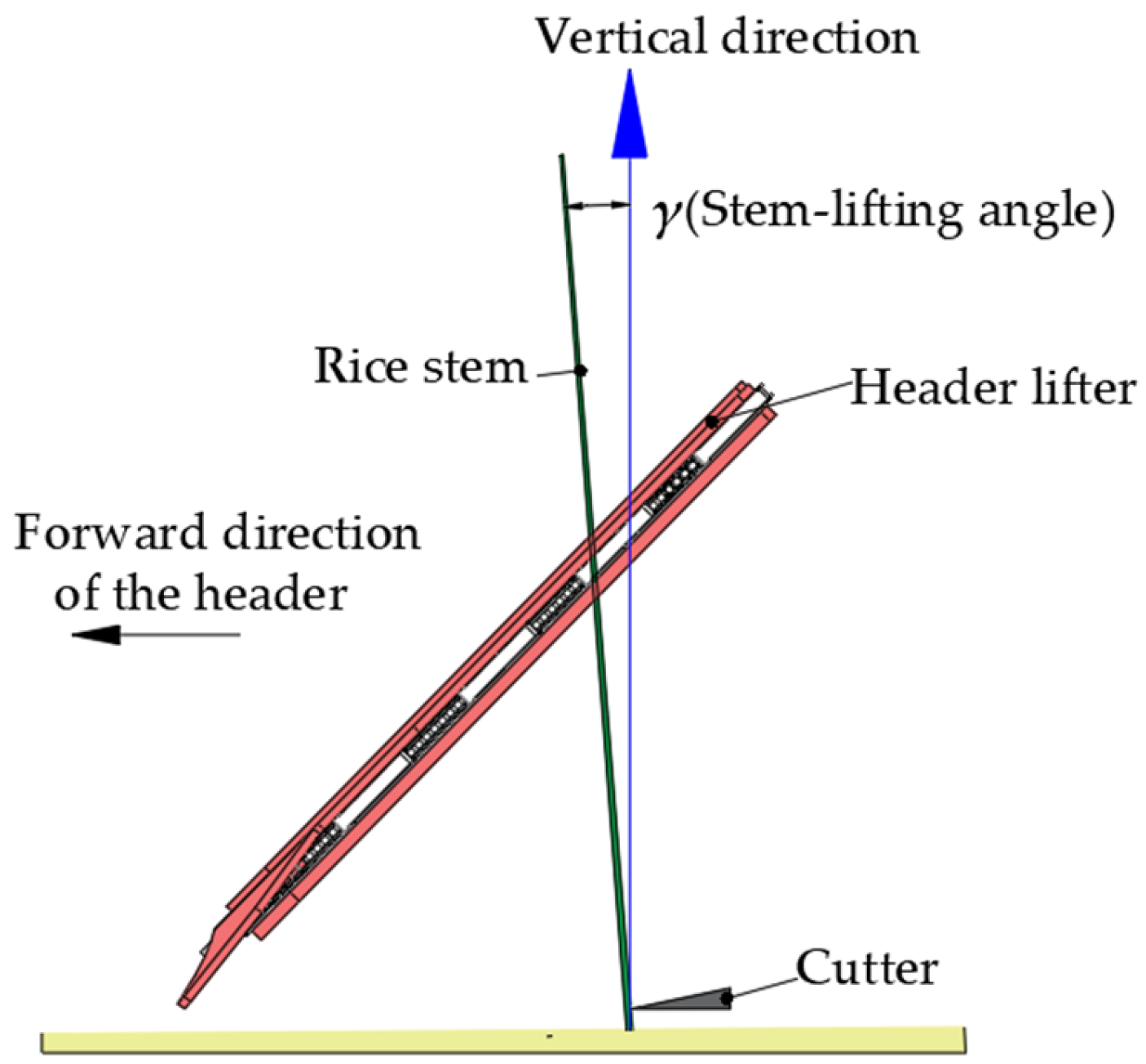
2.1. Working Principle of Header Stem-Lifting Mechanism

Headers (normally 1000 mm in length, 850 mm in width, and 800 mm in height) are categorized into vertical and horizontal types based on their structural characteristics. The vertical header, characterized by compactness, a lightweight design, and high maneuverability, demonstrates superior adaptability for small-field rice harvesting on hilly terrains. In this study, we aim to address operational challenges in these regions; to this end, we employ a vertical header structure with a working width of 0.5 m, enabling dual-row harvesting in a single pass while minimizing machine dimensions. The bundling mechanism incorporates a C-type knotter, selected for its compactness, cost-effectiveness, and operational simplicity, effectively meeting the practical demands of hilly terrain rice harvesting. The finalized header structure is illustrated in Figure 1, and the working process is shown in Figure 2.
The stem-lifting mechanism comprises dividers, lifting fingers, sprocket groups, double-row lifting chains, and a chain box with guide rails, as shown in Figure 3. The fingers, hinged to the lifting chain and positioned obliquely above the cutter, perform dual functions of stem division and lifting. During operation, the chain-driven finger assembly exhibits dual movements, including translational motion along the guide rails and periodic telescopic movements around the hinge axis. Initially, downward chain motion keeps the fingers retracted under guide rail constraints. Upon reaching the lower sprocket area, the curvature changes in the rails trigger finger extension, enabling insertion into the rice plant base for upward lifting. Subsequently, coordinated action with the cutter and clamping device ensures continuous stem conveyance to the cutting unit. After completing a lifting cycle, the fingers retract into the chain box, initiating the next operational phase.

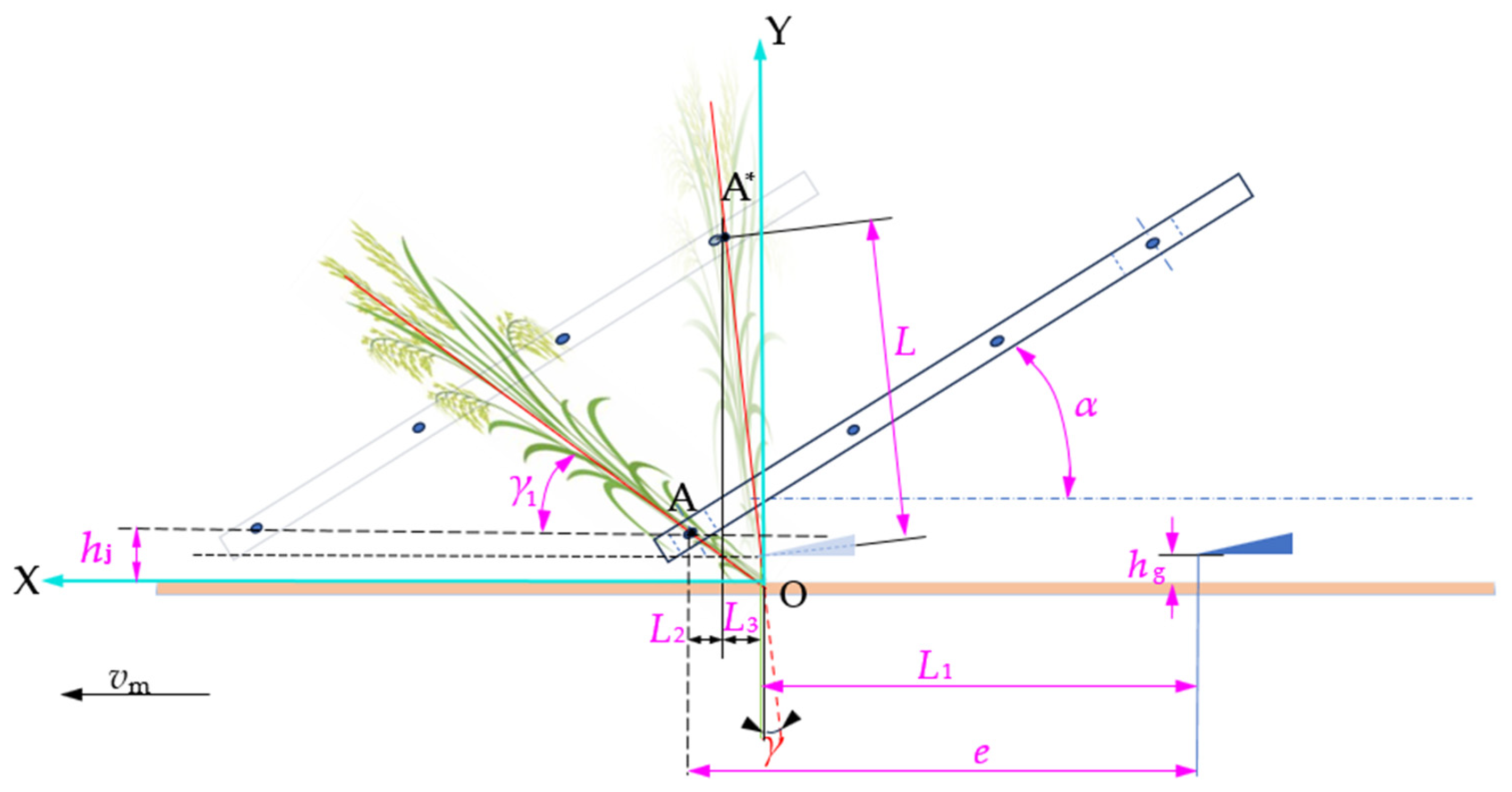
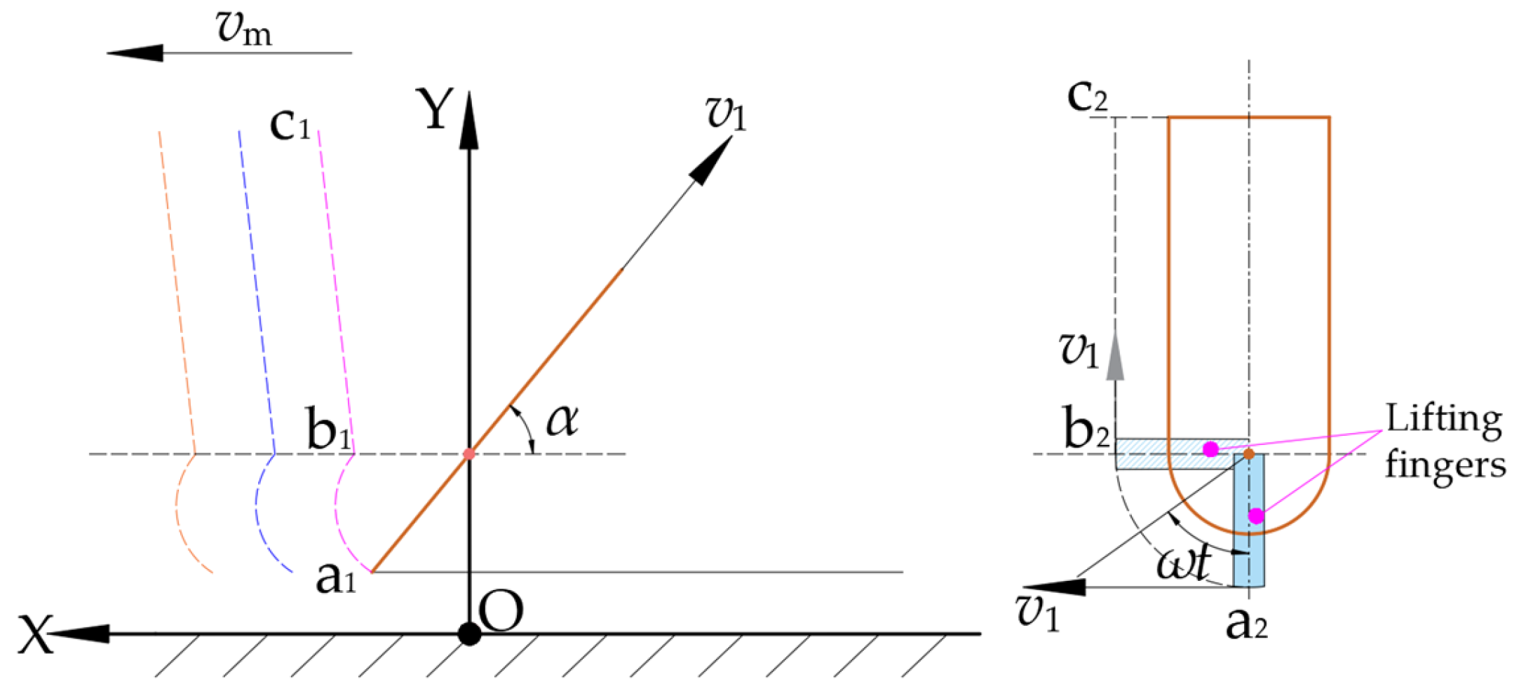
2.2. Analysis of Stem-Lifting Process

Effective rice harvesting requires cutting plants in an upright, clamped state to ensure orderly conveying [23]. The stem-lifting mechanism restricts the rice plant degrees of freedom perpendicular to the operational direction, enabling precise support along the header’s trajectory. However, parameters such as header forward speed, lifting speed, and header tilt angle may induce a variable stem-lifting angle, directly affecting conveying quality. In this study, we analyze stem posture variations during lifting to optimize these parameters. A Cartesian coordinate system (X-Y plane) is established with the stem’s growth point O as the origin, as illustrated in Figure 4, where the X-axis aligns with the header forward direction and the Y-axis extends vertically upward.
In the figure above, A and A* denote the initial and final stem-lifting positions, respectively; L corresponds to the supported crop length; L1 is the header advancement distance during one complete stem-lifting cycle; L2 quantifies the horizontal displacement between the initial A and final A* support positions; L3 is the X-axis projection of vector OA*; hj is the vertical distance from the lower sprocket center to the ground; hg defines the cutter height relative to the ground; γ is the stem-lifting angle at process completion; γ1 represents the complementary angle of rice lodging inclination; α denotes the header tilt angle; e refers to the cutter installation position; and vm corresponds to the header forward speed.
The motion of the stem support point is derived from the vector synthesis of header forward movement and finger linear motion. Taking initial support point A as the reference, the displacement equation for terminal support point A* is
x * = v 1 t g cos α y * = v 1 t g sin α
where v1 represents the traveling speed of the lifting fingers, tg is the time to complete a stem-lifting process, x* is the X-axis coordinate of stem-lifting position A*, and y* is the Y-axis coordinate of support point A*.
Based on the geometric relationships in Figure 4, the stem-lifting angle (γ) satisfies
tan γ = L 3 y * + h j L 3 = e L 1 L 2 L 1 = v m t g L 2 = x *
Solving Equation (2) yields
tan γ = e v m t g 1 k b cos α k b sin α + h j v m t g
where kb denotes the stem-lifting speed ratio coefficient, defined as the ratio of the finger linear velocity (v1) to the header forward speed (vm).
Equation (3) reveals that the stem-lifting angle (γ) depends on the cutter installation position (e), the stem-lifting speed ratio coefficient (kb), the header tilt angle (α), and the vertical distance from the lower sprocket center to the ground (hj). Following agricultural machinery standards [24] and hilly terrain requirements, hj is fixed at 150 mm, and the cutter installation position (e) ranges from 230 to 300 mm.
The header tilt angle (α) influences structural compactness and operational stability. A smaller header tilt angle (α) necessitates a larger cutter installation position (e) to maintain effective stem support length (L), increasing structural size and weight nonlinearly. Conversely, a larger header tilt angle (α) enhances compactness but exacerbates lateral disturbances, increasing stem collapse risk. Additionally, an increase in the operating speed of the lifting fingers intensifies the transmission system vibrations, reducing header durability. Drawing from prior optimization frameworks [25], the header tilt angle (α) is constrained to 50–70°.
Finger speed critically impacts harvesting quality due to direct panicle contact [26]. Kinematic analysis shows that fingers execute three sequential actions: extension for stem engagement, upward guidance, and retraction to avoid interference. The fingertip trajectory combines translational motion (in the header forward direction) and rotational motion (around the sprocket axis), as shown in Figure 5. Taking vertical projection point O of the passive sprocket center on the ground as the origin, a coordinate system is established, where the positive direction of the X-axis coincides with the forward direction of the machine, and the positive direction of the Y-axis is vertically upward from the ground. On the trajectory curve, segment ab represents the stem-dividing phase, and segment bc represents the stem-lifting phase. In the figure, trajectories a1b1c1 and a2b2c2 are the projections of stem-lifting trajectory abc onto the XOY plane and the chain box plane, respectively.
In the X-Y plane projection (a1b1c1), the fingertip velocity components are
v 1 = 2 π r b n b 60 v 2 = v m v 1 cos α v 3 = v 1 sin α
In the chain box plane projection (a2b2c2), the components become
v 2 * = v m v 1 * cos α sin ω b t b v 1 * = 2 π ( r b + l ) n b 60 v 3 * = v 1 * sin α sin ω b t b
where v1, v2, and v3 represent the rotational linear velocity, the X-axis component velocity, and the Y-axis component velocity of the lifting finger, respectively; v1*, v2*, and v3* denote the rotational linear velocity, the X-axis component velocity, and the Y-axis component velocity at the fingertip, respectively; nb, rb, and ωb correspond to the rotational speed, radius, and angular velocity of the passive sprocket, respectively; and tb and l are the lifting duration (the time taken for the stem-lifting finger to rotate from position a2 to b2) and finger length, respectively.
The absolute lifting velocity of the finger is synthesized from the header forward velocity (vm) and the finger rotational linear velocity (v1). It is specified that when the angle γ between v and the plumb direction is forward, the absolute lifting velocity of the finger is negative, and when γ is backward, it is positive, as shown in Figure 6.
The lifting equation of the fingers can be derived as
tan γ = v 1 cos α v m v 1 sin α = k b cos α 1 k b sin α
Equation (6) indicates that the lifting trajectory is dependent on the stem-lifting speed ratio coefficient (kb) and the header tilt angle (α). For shedding-prone rice varieties, optimal performance (minimized loss) requires a conveying velocity v1 ≤ 1.5 m/s [27] and γ = 0° [27]. Substituting these constraints into Equation (6) yields
50 ° α 70 ° v 1 cos α = v m v 1 1.5
Solving Equation (7) gives the parameter range of 1.56 ≤ kb ≤ 2.14.

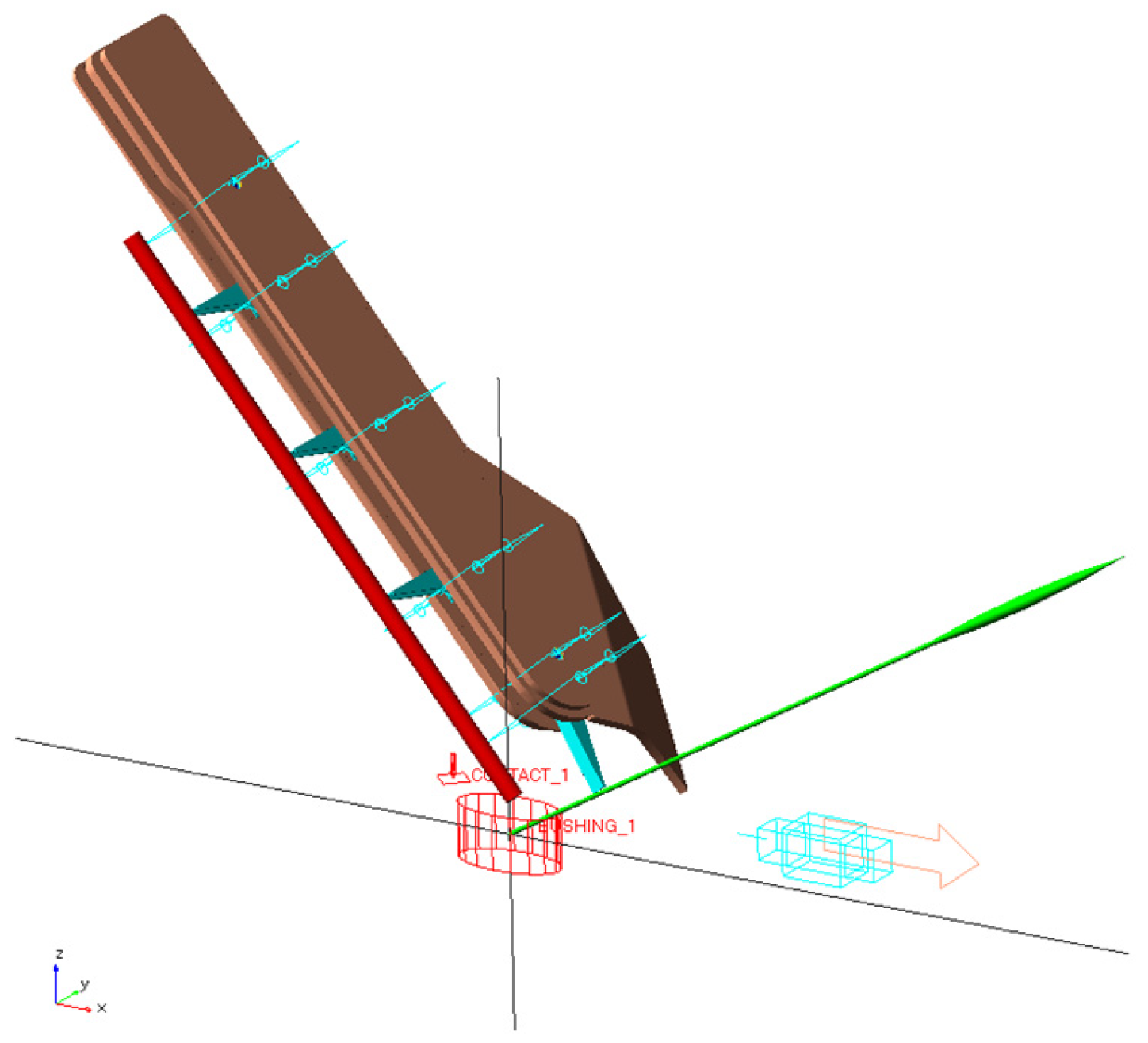
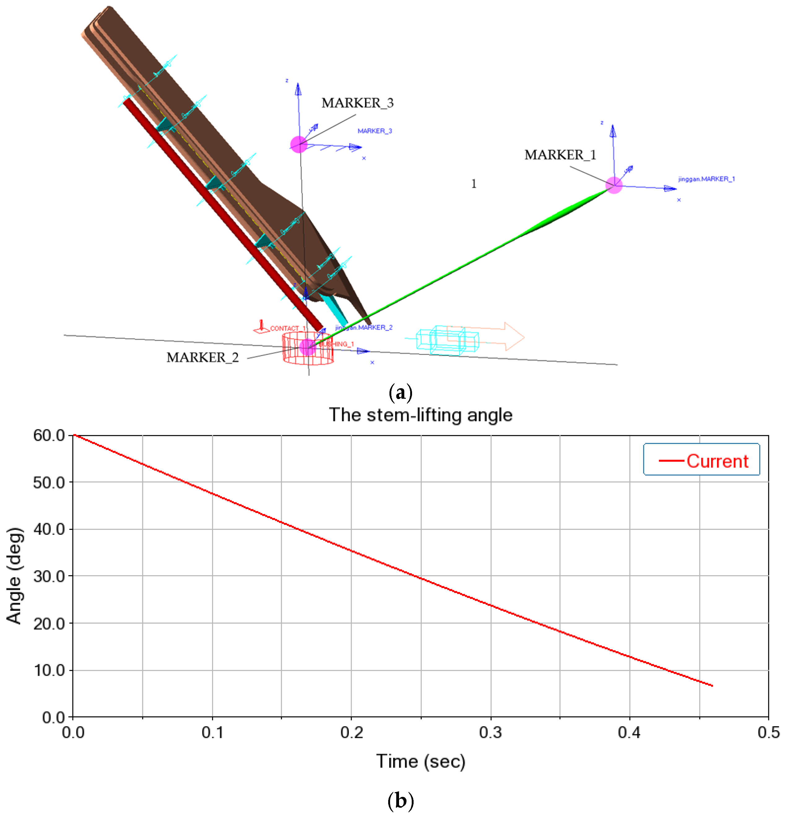
2.3. Dynamic Simulation Model of Header Stem-Lifting Mechanism

The header employs a symmetrical dual-lifting mechanism, where left and right lifters exhibit identical operational performance. Thus, the left lifter was selected for simulation to streamline analysis. A 3D model of the left lifter was developed in SolidWorks 2021 (as shown in Figure 7), exported in x_t format, and imported into the ADAMS 2020 multibody dynamics environment. Following import, Boolean merge operations were employed to unify the auxiliary lifting rods and finger guide rails. A ground coordinate system was established with translational constraints and linear motion drivers. A chain drive system was configured at the driving and driven sprocket positions by using the adams machinery module, with revolute joints being applied to the finger mechanism. The simulation duration was set to 0.46 s, 0.53 s, and 0.6 s (corresponding to cutter installation distances), using a step size of 200 steps.
Rice stems were modeled as rigid cylindrical bodies with uniform cross-sectional mass distribution [28], neglecting minor deformations and internodal variations during lifting. The stem lodging angle was fixed at 60°. Multibody contact relationships were defined between stems and components (lifting fingers, auxiliary rods, and guide rails). A soil interaction model was implemented at the stem root based on articulated constraints and bushing forces to simulate soil restraint dynamics [29]. The finalized rigid-body dynamic model is shown in Figure 8, with material properties and parameters detailed in Table 1 [30,31,32].
A motion analysis method based on feature marker points was developed to quantify the stem-lifting angles. Three markers (Marker_1, Marker_2, and Marker_3) were positioned at the stem apex, stem base, and along the Z-axis of the operational grid coordinate system, respectively, as shown in Figure 9a. The dynamic evolution of the stem-lifting angle (γ) during the operational cycle was obtained by tracking the spatial relationships among the markers in real time, as illustrated in Figure 9b, where each time point represents the instantaneous stem-lifting angle.

2.4. Box–Behnken Simulation Experimental Method

2.4.1. Experimental Factors and Levels

Building on the coupled dynamics model, a three-factor, three-level Box–Behnken design was implemented to optimize the stem-lifting parameters. The header forward speed was fixed at 500 mm/s, with the stem-lifting speed ratio coefficient (kb), the cutter installation position (e), and the header tilt angle (α) being selected as independent variables. The stem-lifting angle (γ) served as the response variable. Orthogonal experiments were conducted with the ADAMS simulation model to evaluate the factor effects on the stem-lifting angle. The coded factor levels are summarized in Table 2.

2.4.2. Evaluation Index

The stem-lifting mechanism’s primary function is to achieve stem uprightness and alignment for optimal vertical posture during cutting. The instantaneous stem-lifting angle (γ), defined as the planar angle between the stem axis and vertical direction, directly governs harvesting quality, as shown in Figure 10. Thus, the stem-lifting angle (γ) at the critical cutting instant was selected as the evaluation metric, with smaller values indicating superior uprightness and operational performance.

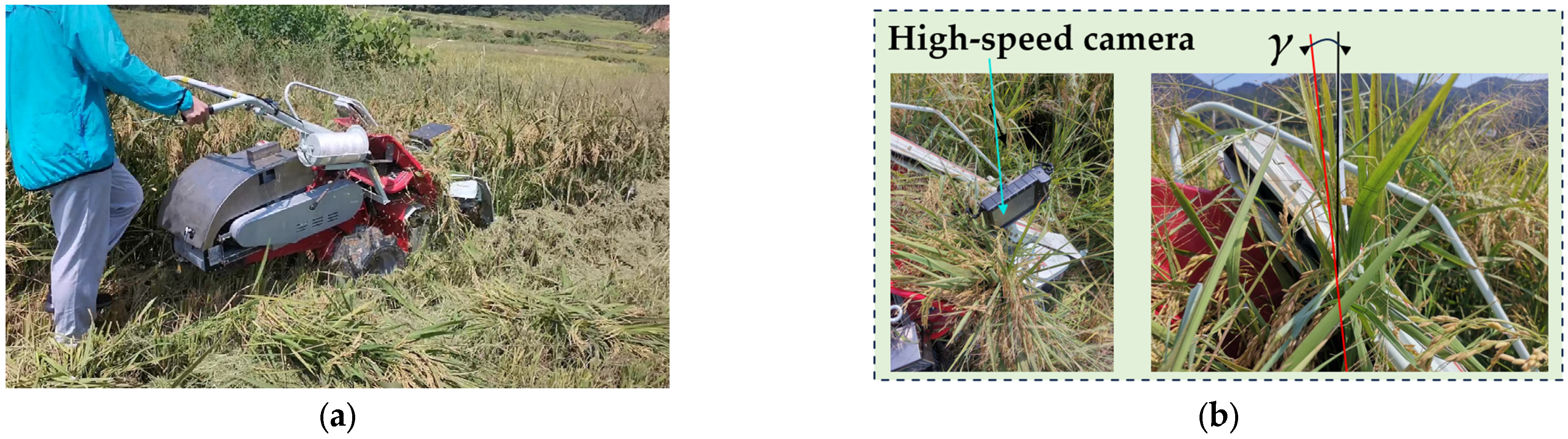
2.5. Field Experimental Method

A prototype electric rice reaper binder was assembled by integrating the self-developed header with a C-type knotter bundling mechanism to validate the optimized header design. Field trials were conducted in October 2024 at Wanxin Family Farm (Pucheng County, Nanping, China) by using mature Qingyou 308 rice (average plant height: 0.91 m; Figure 11a). The experiments adhered to Chinese National Standard GB/T 24686-2009 [33] and Industry Standard NY/T 498-2013 [34], with quantitative assessments focusing on the stem-lifting angle and the header loss rate.
Stem-lifting angle measurement: A high-speed camera (Fastec Imaging Corporation, TS3 100SC4, San Diego, CA, USA) was mounted on the right lifter’s platform, with a reference marker at the left lifter’s guide rail end. During stable operation, 10 s of continuous video was recorded in a flat field section. In post-processing, five frames were randomly selected, and the stem-lifting angle (γ) was measured by using image analysis software. This procedure was repeated five times, and the mean value was calculated as the final result, as shown in Figure 11b.
Header loss rate measurement: Before harvest, five 1 m2 plots were demarcated based on the five-point sampling method. Manual panicle cutting, threshing, and weighing were performed to determine the average grain mass per unit area (Wd1), and naturally shed grains (Wz1) were also collected. During trials, the prototype operated at 0.5 m/s, with a 30 m stable harvesting zone selected for testing. After harvest, three 2 m subplots (1 m2 each) were established to collect fallen grains from missed cutting or panicle shedding. The loss mass per unit area (Wq1) was measured. This procedure was repeated three times, and the header loss rate (Ws1) was calculated as
W s 1 = W q 1 W z 1 W d 1 × 100 %

3. Results

3.1. Regression Prediction Model for Lifting Performance

Seventeen simulation trials were conducted in ADAMS based on the orthogonal experimental design; each group was repeated three times, and the mean value was taken to reduce random errors, as shown in Table 3.

3.2. ANOVA Results

A regression analysis performed by using Design-Expert 13.0 allowed us to establish a predictive model for the stem-lifting angle (γ) as a function of the experimental factors. Significance testing and model fitness analysis were conducted, and the ANOVA results are presented in Table 4.
The ANOVA results in Table 4 indicate that the regression model for the stem-lifting angle (γ) is statistically valid with significant model terms (p < 0.05) and a non-significant lack of fit (p > 0.05). The regression model revealed that the stem-lifting speed ratio coefficient (kb), the cutter installation position (e), the header tilt angle (α), and their interactions (kbe and kbα) and quadratic terms (kb2, e2, and α2) significantly influenced the stem-lifting angle (γ). Notably, it can be seen from the p value that the interaction of showed no significant effect (0.2065 > 0.05). Based on the F-values [35], factor importance ranked as follows: kb > α > e. The derived regression equation is
γ = 2.18 2.19 k b 0.62 e + 1.57 α + 1.26 k b e 2.51 k b α 0.39 e α + 2.52 k b 2 + 2.08 e 2 + 3.62 α 2

4. Discussion

4.1. Analysis of Interaction Effects on Evaluation Index

A response surface analysis was conducted by using Design-Expert 13.0 to elucidate the interaction mechanisms between operational parameters influencing the stem-lifting angle (γ); the third factor was fixed at its 0 level, as shown in Figure 12.
Figure 12a demonstrates that, under a constant stem-lifting speed ratio coefficient (kb), the stem-lifting angle (γ) follows a nonlinear parabolic trend, initially decreasing and then increasing with larger cutter installation positions (e). Similarly, at fixed cutter installation positions (e), the stem-lifting angle (γ) exhibits a concave trajectory as the stem-lifting speed ratio coefficient (kb) increases. This behavior arises because moderate increases in either parameter enhance the header’s ability to support rice stems, improving upright posture and reducing the stem-lifting angle. However, excessive values overextend stems beyond 90°, causing the stem-lifting angle to rebound and form a parabolic pattern.
Figure 12b demonstrates that under a constant stem-lifting speed ratio coefficient (kb), the stem-lifting angle (γ) initially decreases and subsequently increases with the increase in the header tilt angle (α), reaching a minimum at α = 62–66°. Similarly, at fixed α, the stem-lifting angle (γ) follows a concave trajectory as kb increases, attaining minima at kb = 2.024–2.140. Mechanistically, excessively small tilt angles (α < 60°) induce stem over-tilting (>90°), while increasing α to the optimal range (62–66°) optimizes stem posture and minimizes the stem-lifting angle (γ). However, excessively large tilt angles (α > 66°) weaken the header’s stem support, leading to a rebound of the stem-lifting angle. Suboptimal coefficients (kb < 2.024) disrupt lifting continuity, causing partial stem fallback and elevated the stem-lifting angle (γ), whereas excessive coefficients (kb > 2.140) over-lift stems beyond 90°, as well as increasing the stem-lifting angle (γ). These findings underscore the necessity of balancing kb and α to maintain γ within the ideal operational range, thereby minimizing harvest losses and increasing the efficiency of rice reaper binders on hilly terrains.

4.2. Parameter Optimization

Minimizing the stem-lifting angle (γ) is critical to ensuring reliable, high-performance harvesting with an electric rice reaper binder. The operational parameters were optimized by defining an objective function and constraints to minimize the stem-lifting angle based on the optimization module in Design-Expert 13.0.
γ = max f ( k b , e , α ) s . t . 1.56 k b 2.14 230 e 300 50 α 70
We solved the multi-objective optimization equation and identified the optimal parameter combination as a stem-lifting speed ratio coefficient (kb) of 2.14, a cutter installation position (e) of 258.79 mm, and a header tilt angle (α) of 62.63°. Under these conditions, the theoretical stem-lifting angle (γ) was calculated as 2.36°. A multibody dynamics simulation was reconstructed in ADAMS with the optimal settings to validate the efficacy of the optimized parameters. The simulation results yielded a measured stem-lifting angle (γ) of 2.31°, showing a relative error of 2.12% against the theoretical value. This strong agreement confirms the reliability of the optimized parameters for practical applications.

4.3. Field Experimental Results and Analysis

Field experiments were conducted in standard test plots following the protocol outlined in Section 2.5 to validate the optimized header’s performance. The key metrics included the stem-lifting angle (γ) and the header loss rate measured post-harvest, and the results are summarized in Table 5 and Table 6.
The analysis of the experimental data in Table 5 and Table 6 revealed that the optimized header achieved a mean stem-lifting angle of 2.44°, exhibiting a 3.39% relative error compared with the theoretical value (2.36°). This alignment confirms the optimization strategy’s reliability. Notably, the design meets the stem-lifting angle (γ < 7°) threshold specified by the Agricultural Machinery Design Manual, with smaller angles correlating with higher operational quality. However, ideally, the relative measurement values of each group should not differ significantly. In the actual test, the relative measurement values of the fourth and fifth groups differed by 7.62%, which is a large gap. The reasons for this phenomenon are as follows: First, fluctuations in field topography or differences in straw moisture content changed the stem-lifting angle. Second, it is also related to the operator’s operation. If the operation is improper and the header does not fit the ground, this also causes large fluctuations in the stem-lifting angle. The third reason can be identified in the influence of the flexible deformation of rice stems on the stem-lifting angle. The optimized header reduced losses caused by excessive lodging, establishing a foundation for improving overall harvester efficiency. Harvesting trials further confirmed grain losses below 10 g/m2 across all test zones and an average header loss rate of 0.59%, representing a 49.6% reduction compared with pre-optimized performance and lower value than the national standard (1%). These results confirm that parameter optimization significantly enhances harvesting quality. The improved design not only fulfills agronomic requirements but also addresses seasonal challenges in hilly regions, providing robust technical support for boosting regional agricultural productivity and economic outcomes.

4.4. Improvement Directions

4.4.1. Comparative Analysis with Similar Studies

In this section, existing research is reviewed and compared with the present study. Liu et al. [10] optimized header parameters with orthogonal experiments, but their focus remained on single components, showing a lack of analysis of synergistic interactions among multiple mechanisms. The work by Liang, S. et al. [11] shared the same goal of reducing losses for small agricultural machinery employed on complex terrains as this study, but their research work targeted the overall optimization of combine harvesters, whereas we focused on dynamic parameter matching for headers. Niu et al. [12], while also combining simulation and field tests, primarily developed profiling control algorithms, providing technical complementarity to the structural parameter collaborative optimization in this study. Zareei et al. [17], similar to the authors of this study, used multi-factor analysis to reduce losses, but their conclusions based on statistical tests lacked support from dynamic mechanisms. Qing, Y. et al. [21] employed orthogonal combination tests, but their optimization focused on self-cleaning efficiency, whereas in this study, we innovatively established the stem-lifting angle (γ) as the core evaluation index for rice harvesting in hilly areas.
These studies generally focus on header optimization and harvest loss control, commonly based on methods such as orthogonal experiments, multi-factor analysis, or simulation modeling, with emphases on multi-crop header adaptability design, component lightweighting, or single-parameter optimization (e.g., self-cleaning efficiency, profiling control algorithms, and structural weight reduction). In contrast, in this study, we address the unique needs of small electric rice reaper binders employed on hilly terrains, take the stem-lifting angle as the core optimization index, and determine the multiparameter synergistic mechanism between stem posture and header parameters (the speed ratio coefficient, the cutter position, and the header tilt angle) by employing ADAMS multibody dynamics modeling. This represents an improvement upon the traditional optimization framework of “single component–single scenario”, providing a reference for the low-loss design of rice harvesting on complex terrains.

4.4.2. Limitations

In this study, we simplified rice stems as rigid cylinders, ignoring effects of flexible deformation and internodal differences. While this rigid model simplified dynamics calculations, it introduced limitations: Stem flexibility caused a 3.39% error in stem-lifting angles (a measured value of 2.44° vs. a theoretical value of 2.36°). Furthermore, the use of idealized contact forces due to internodal stiffness/mass variations may affect lodging risk predictions. However, for the lodging-resistant “Qingyou 308” variety (0.91 m plant height, with high basal strength), the model proved valid when the stem-lifting angle trends were optimized—parameter optimization reduced harvest losses by 49.6%—verifying core parameter interactions (among the speed ratio, the cutter installation position, and the header tilt angle). Notably, flexible deformation may amplify angle errors in tall, lodging-prone varieties. Future studies could integrate discrete element methods with internodal stiffness variations to enhance model universality.

4.4.3. Economic Evaluation and Engineering Application Prospects

The loss rate in the field test of the optimized header is 0.59%, a 49.6% reduction compared with the pre-optimized header. If we consider the economic evaluation under the conditions of an annual harvest of 100 mu and a yield of 500 kg per mu in hilly areas, the optimized electric rice reaper binder can reduce losses by approximately 3 kg of rice per mu. Additionally, using electricity can save costs, with a comprehensive annual economic benefit exceeding CNY 500, demonstrating a significant input–output ratio.

5. Conclusions

In this study, we integrated theoretical modeling, dynamic simulation, and field experimentation to optimize the header parameters of an electric rice reaper binder, achieving significant improvements in operational performance. The key findings are summarized as follows:
  • The theoretical analysis allowed us to identify the critical factors influencing stem-lifting performance, i.e., the stem-lifting speed ratio coefficient, the cutter installation position, and the header tilt angle, alongside their operational ranges. A multibody dynamic simulation model of the stem-lifting mechanism was developed by using the ADAMS platform, which enabled the visualization and analysis of the lifting process.
  • A Box–Behnken experimental design was adopted to develop a regression model with the stem-lifting angle as the response variable, quantitatively correlating the operational parameters with performance. Notably, it can be seen from the p value in the analysis of variance table that the interaction between the cutter installation position and the header tilt angle showed no significant effect on the test index, whereas all other factors and interactions exhibited statistically significant impacts.
  • Optimization based on response surface methodology yielded the optimal parameter combination, i.e., a stem-lifting speed ratio coefficient of 2.14, a cutter installation position of 258.79 mm, and a header tilt angle of 62.63°, achieving a theoretical stem-lifting angle of 2.36°. Field validation confirmed a measured stem-lifting angle of 2.44°, corresponding to a relative error of 3.39%. Concurrently, the harvesting loss rate was experimentally determined to be 0.59%, demonstrating a 49.6% reduction compared with pre-optimization levels. These outcomes verify the accuracy of the simulation model and the practical efficacy of the optimized header. The enhanced design not only fulfills operational requirements but also provides a viable technical solution for mechanized rice harvesting on hilly terrains, addressing critical challenges in regional agricultural productivity.

Author Contributions

Conceptualization, J.R., X.W. and S.Z.; methodology, J.R.; software, Z.L.; validation, C.Y.; formal analysis, Z.L.; investigation, Z.L.; resources, D.B.; data curation, D.B.; writing—original draft preparation, J.R. and D.B.; writing—review and editing, J.R., X.W. and S.Z.; visualization, J.W.; supervision, X.W. and S.Z.; project administration, J.R.; funding acquisition, X.W. and S.Z. All authors have read and agreed to the published version of the manuscript.

Funding

This research study was funded by the Fujian University Engineering Research Center for Modern Agricultural Equipment (grant number PTJH17004) and the Regional Development Project of Fujian Provincial Department of Science and Technology (grant number 2023H4032).

Institutional Review Board Statement

Not applicable.

Data Availability Statement

The data will be made available upon reasonable request from the corresponding author.

Acknowledgments

The authors would like to express their gratitude to the Fujian University Engineering Research Center for Modern Agricultural Equipment and the reviewers who provided helpful suggestions for this manuscript.

Conflicts of Interest

The authors declare no conflicts of interest.

Abbreviations

The following abbreviations are used in this manuscript:
ANOVAanalysis of variance
RSMresponse surface methodology

References

  1. Duppala, M.; Srinivas, T.; Rao, L.V.S.; Suneetha, Y.; Sundaram, R.M.; Prasannakumari, V.; Satyanaryana, P.V.; Abdulfiyaz, R.; Raveendra, C.H.; Singh, G. Marker-Assisted Pedigree Breeding to Enhance Resistance Against Bacterial Blight, Blast, And Tolerance to Low Soil Phosphorus in the Indian Elite Rice Cultivar Mtu1121. Cereal Res. Commun. 2025, 1–18. [Google Scholar] [CrossRef]
  2. John Deere. John Deere China Official Home Page. Available online: https://www.deere.com.cn/zh/ (accessed on 11 March 2025).
  3. CLAAS. CLAAS Group China Official Home Page. Available online: https://www.claas.com/zh-cn/agricultural-machinery/combines (accessed on 11 March 2025).
  4. Case IH. Case IH (China) Co., Ltd. Official Home Page. Available online: https://www.caseih-china.cn/ (accessed on 11 March 2025).
  5. Li, Y.; Li, Y.; Xu, L.; Hu, B.; Wang, R. Structural Parameter Optimization of Combine Harvester Cutting Bench. Trans. Chin. Soc. Agric. Eng. 2014, 30, 30–37. [Google Scholar]
  6. Slaughter, D.C.; Giles, D.K.; Downey, D. Autonomous Robotic Weed Control Systems: A Review. Comput. Electron. Agric. 2008, 61, 63–78. [Google Scholar] [CrossRef]
  7. Takashi, F. Collision Vibration Characteristics with Interspace in Knife Driving System of Combine Harvester. Eng. Agric. Environ. Food 2012, 5, 115–120. [Google Scholar]
  8. Cao, Z.; Li, Q.; Chen, L.; Zhou, Y.; Nie, J.; Chen, Q.; Xiao, Y.; Zhou, S.; Zhang, L. Structural Design and Testing of a Corn Header for Soybean–Corn Intercropping. Agriculture 2025, 15, 123. [Google Scholar] [CrossRef]
  9. Shi, R.; Dai, F.; Zhao, W.; Liu, X.; Liang, Z.; Pan, H.; Chen, J. Analysis of the Anti-Winding Mechanism for the Interaction Between Flax Stem and Harvest Header in Hilly Area. Trans. Chin. Soc. Agric. Eng. 2025, 41, 11–19. [Google Scholar]
  10. Liu, Y.; Luo, C.; Zong, W.; Huang, X.; Ma, L.; Lian, G. Optimization of Clamping and Conveying Device for Sunflower Oil Combine Harvester Header. Agriculture 2021, 11, 859. [Google Scholar] [CrossRef]
  11. Liang, S.; Jin, C.; Zhang, F.; Kang, D.; Hu, M. Design and Experiment of 4LZG-3.0 Millet Combine Harvester. Trans. Chin. Soc. Agric. Eng. 2015, 31, 31–38. [Google Scholar]
  12. Niu, Y.; Li, R.; Liu, W.; Rong, K.; Hong, H.; Zhang, G. Development and Testing of the Adaptive Control System for Profiling Grain Header. Agriculture 2025, 15, 473. [Google Scholar] [CrossRef]
  13. Luo, Y.; Liao, Z.; Shi, S.; Dai, J.; Yuan, K.; Zhao, J.; Li, Y.; Zhao, Z. Design and Testing of a 2-DOF Adaptive Profiling Header for Forage Harvesters. Agronomy 2024, 14, 1909. [Google Scholar] [CrossRef]
  14. Tan, H.; Wang, G.; Zhou, S.; Jia, H.; Qu, M.; Xiang, M.; Gao, X.; Zhou, Z.; Li, H.; Zou, Z. Design and Experiment of Header Height Adaptive Adjustment System for Maize (Zeamays L.) Harvester. Sustainability 2023, 15, 14137. [Google Scholar] [CrossRef]
  15. Qiu, S.; Li, K.; Hu, Y.; Pan, B.; Wang, Z.; Yuan, X.; Cui, Q.; Tang, Z. Design and Experimentation of the Millet Combine Harvester Header. Machines 2024, 12, 636. [Google Scholar] [CrossRef]
  16. Bawatharani, R.; Bandara, M.; Senevirathne, D. Influence of Cutting Height and Forward Speed on Header Losses in Rice Harvesting. Int. J. Agric. For. Plant. 2016, 4, 1–9. [Google Scholar]
  17. Zareei, S.; Pour, S.A.; Moghaddam, M.; Sahrayan, H. Optimum Setting of Combine Header for Wheat Harvesting Using Taguchi Method. Res. Crop. 2012, 13, 1142–1146. [Google Scholar]
  18. Tian, Y.; Leis, K.; Zeng, Z. Retrofitting and Testing of a Pull-Type Small-Grain Combine Harvester. Agronomy 2023, 13, 1057. [Google Scholar] [CrossRef]
  19. Liu, W.; Zeng, S.; Chen, X. Vortex Cleaning Device for Rice Harvester: Design and Bench Test. Agriculture 2024, 14, 866. [Google Scholar] [CrossRef]
  20. Wang, G.; Li, Y.; Wang, R.; Liu, Y. Dynamic load distribution property of transmission system during rice harvesting process. Adv. Mech. Eng. 2024, 16, 16878132231224175. [Google Scholar] [CrossRef]
  21. Qing, Y.; Chen, L.; Chen, D.; Wang, P.; Sun, W.; Yang, R. Simulation and Optimization of a Self-Cleaning Device for the Header of a Rice Seed Harvester Using Fluent–EDEM Coupling. Agriculture 2024, 14, 2312. [Google Scholar] [CrossRef]
  22. Liu, W.; Zeng, S.; Chen, X. Design and Experiment of Adaptive Profiling Header Based on Multi-Body Dynamics–Discrete Element Method Coupling. Agriculture 2024, 14, 105. [Google Scholar] [CrossRef]
  23. Shan, Y.; Liao, Q.; Wan, X.; Yuan, J.; Chen, L.; Liao, Y. Design and Experiment of Self-propelled Six-row Harvester for Oilseed Rape Shoot. Trans. Chin. Soc. Agric. Mach. 2024, 55, 93–104. [Google Scholar]
  24. China Academy of Agricultural Mechanization Sciences (Ed.) Agricultural Machinery Design Manual (Lower Volume); China Agricultural Science and Technology Press: Beijing, China, 2007; pp. 877–1028. ISBN 978-7-80233-335-2. [Google Scholar]
  25. Gong, Y. Design and Test of Boat-Type Harvesting Platform for Deep-Water Paddy Field. Master’s Thesis, Hunan Agricultural University, Changsha, China, 2021. [Google Scholar]
  26. Yan, X. The Design of Small Wheat and Cereal Grain Combine Harvester and Baler. Agric. Technol. Equip. 2021, 13–14+17. (In Chinese) [Google Scholar] [CrossRef]
  27. Li, B. (Ed.) Agricultural Mechanics; China Agricultural Press: Beijing, China, 2003; pp. 155–195. ISBN 7-109-08403-5. [Google Scholar]
  28. Chen, H.; Dun, G. Optimization of Parameters for Soybean Lifter Based on Dynamic Simulation of Virtual Prototype. Trans. Chin. Soc. Agric. Eng. 2012, 28, 23–29. [Google Scholar]
  29. He, Y.; He, J.; Fang, D.; Du, X.; Xu, F. Dynamic Simulation Test and Analysis of Cerasus humilis Lifting Branches Based on ADAMS. Trans. Chin. Soc. Agric. Eng. 2020, 10, 72–75. [Google Scholar]
  30. Lei, X.; Yang, W.; Yang, L.; Liu, L.; Liao, Q.; Ren, W. Design and Experiment of Seed Hill-seeding Centralized Metering Device for Rapeseed. Trans. Chin. Soc. Agric. Mach. 2020, 51, 54–64. [Google Scholar]
  31. Xu, C. Research and Experiment on the Stripping Mechanism of Concave Combs and Increasing Flow Header for Stripping Prior to Cutting. Ph.D. Dissertation, Northeast Agricultural University, Harbin, China, 2023. [Google Scholar]
  32. Xia, J.; Zhang, P.; Yuan, H.; Du, J.; Zheng, K.; Li, Y. Calibration and Verification of Flexible Rice Straw Model by Discrete Element Method. Trans. Chin. Soc. Agric. Mach. 2024, 55, 174–184. [Google Scholar]
  33. GB/T 24686-2009; Rice Reaper and Binder. Standardization Admi-nistration of the People’s Republic of China (SAC): Beijing, China, 2009.
  34. NY/T 498-2013; Combine Harvester—Operating Quality. Ministry of Agriculture and Rural Affairs of the People’s Republic of China: Beijing, China, 2013.
  35. Xin, S.; Zhao, W.; Shi, L.; Dai, F.; Feng, B.; Yan, Z.B.; Lv, D.Y. Design and Experiments of the Clamping and Conveying Device for the Vertical Roller Type Corn Harvesting Header. Trans. Chin. Soc. Agric. Eng. 2023, 39, 34–43. [Google Scholar]
Figure 1. The working process of the electric rice reaper binder header.
Agriculture 15 01242 g001
Figure 2. Structural configuration of electric rice reaper binder header.
Agriculture 15 01242 g002
Figure 3. Schematic diagram of the stem-lifting device.
Agriculture 15 01242 g003
Figure 4. Schematic diagram of the header stem-lifting process. (The “*” indicates the position of the supporting point A upon completion of the supporting-and-tilting movement, denoted as A*.)
Agriculture 15 01242 g004
Figure 5. Motion trajectory of lifting finger. (The dark blue area indicates the position of the lifting finger when it is at a2. The light blue indicates the position of the lifting finger when it is at b2.)
Agriculture 15 01242 g005
Figure 6. Absolute velocity analysis of fingertip stem-lifting.
Agriculture 15 01242 g006
Figure 7. Structural configuration of header stem-lifting mechanism.
Agriculture 15 01242 g007
Figure 8. Dynamic simulation model of stem-lifting device.
Agriculture 15 01242 g008
Figure 9. Marking and acquisition of stem-lifting angles during stem-lifting process. (a) Marker point labeling. (b) Header stem-lifting angle acquisition (conditions at this time: vm = 500 mm/s and v1 = 925 mm/s; therefore, kb = 1.85, e = 230 mm, and α = 50°).
Agriculture 15 01242 g009
Figure 10. Schematic diagram of stem-lifting angle.
Agriculture 15 01242 g010
Figure 11. Field experiment: (a) Field operation of electric rice reaper binder. (b) Stem-lifting angle measurement.
Agriculture 15 01242 g011
Figure 12. Response surface analysis of interaction effects on header stem-lifting angle. (a) Interaction effect of kb and e. (b) Interaction effect of kb and α.
Agriculture 15 01242 g012
Table 1. Material properties and coefficients for simulation model configuration.
NameParameterValue
Rice stemPoisson’s ratio0.4
Elastic modulus (Mpa)320
Density (kg/m3)222
SteelPoisson’s ratio0.29
Elastic modulus (Mpa)2.06 × 10⁸
Density (kg/m3)7800
ABSPoisson’s ratio0.394
Elastic modulus (Mpa)200
Density (kg/m3)1060
Rice stem–steel contact coefficientStatic friction coefficient0.46
Rolling friction coefficient0.03
Rice stem–ABS contact coefficientStatic friction coefficient0.41
Rolling friction coefficient0.3
Table 2. Test factors and levels.
Horizontal Coded ValueStem-Lifting Speed Ratio Coefficient,
kb
Cutter Installation Position,
e (mm)
Header Tilt Angle,
α (°)
−11.5623050
01.8526560
12.1430070
Table 3. Test methods and results.
Test No.kbe (mm)α (°)γ (°)
11.562306011.239
22.14230603.478
31.56300607.565
42.14300604.836
51.56265506.153
62.14265507.653
71.562657014.003
82.14265705.458
91.85230506.43
101.85300505.871
111.852307010.669
121.85300708.552
131.85265602.011
141.85265601.934
151.85265602.443
161.85265602.653
171.85265601.848
Table 4. ANOVA results of the stem-lifting angle.
Source of VariationSum of SquaresDegrees of FreedomMean SquareF-Valuep-Value
Model204.53922.7372.58<0.0001 **
kb38.43138.43122.74<0.0001 **
e3.1213.129.950.0161 *
α19.77119.7763.13<0.0001 **
kbe6.3316.3320.220.0028 **
kbα25.23125.2380.56<0.0001 **
0.606810.60681.940.2065
kb226.72126.7285.32<0.0001 **
e218.26118.2658.330.0001 **
α255.18155.18176.21<0.0001 **
Residual2.1970.3131
Lack of fit1.730.56664.60.0871
Error0.492240.123
Total206.7216
Note: ** indicates high significance (p < 0.01); * denotes significance (p < 0.05).
Table 5. Measurement results of stem-lifting angle.
Test NumberOptimized Theoretical Value
(°)
Experimental Value
(°)
Relative Error
(%)
1 2.516.36
2 2.474.66
32.362.283.39
4 2.380.85
5 2.568.47
Average value2.362.443.39
Table 6. Measurement results of harvesting loss rate.
No.Mass Loss Per Square Meter,
Wq1 (g)
Natural Shedding Mass, Wz1 (g)Rice Mass Per Square Meter,
Wd (g)
Harvesting Loss Rate,
Ws1 (%)
Pre-Improvement Field Trial Results (%)
18.15 913.570.55
29.373.12909.490.691.17
37.91 911.920.53
Average value8.483.12911.660.59
Disclaimer/Publisher’s Note: The statements, opinions and data contained in all publications are solely those of the individual author(s) and contributor(s) and not of MDPI and/or the editor(s). MDPI and/or the editor(s) disclaim responsibility for any injury to people or property resulting from any ideas, methods, instructions or products referred to in the content.

