Article

Automation of Rice Transplanter Using Agricultural Navigation

1
School of Agricultural Engineering and Food Science, Shandong University of Technology, Zibo 255000, China
2
College of Biosystems Engineering and Food Science, Zhejiang University, Hangzhou 310058, China
3
Shandong Provincial Key Laboratory of Smart Agricultural Technology and Intelligent Agricultural Machinery Equipment for Field Crops, Zibo 255000, China
*
Author to whom correspondence should be addressed.
Agriculture 2025, 15(11), 1125; https://doi.org/10.3390/agriculture15111125
Submission received: 23 April 2025 / Accepted: 21 May 2025 / Published: 23 May 2025
(This article belongs to the Section Agricultural Technology)

Abstract

:
Rice is the predominant grain crop in China, with its consumption showing a steady annual increase. Due to the diminishing labor force, China’s rice cultivation industry faces significant challenges and has an urgent requirement for automated rice transplanters. This study developed an agricultural navigation system integrating mechatronic-hydraulic control with navigation technologies to automate the rice transplanter’s driving and operational processes. The designed automation devices enable precise control over functions such as steering and working clutch. A path planning methodology was proposed to generate straight-line reference paths by giving target points and to determine the headland turning pattern based on the working width and turning radius of the rice transplanter. Additionally, an operational control strategy based on the finite state machine (FSM) was developed, enabling effective switching of the rice transplanter’s operational states through the designation of key points. The test results showed that the maximum lateral error of the rice transplanter along straight-line paths was 4.83 cm on the cement pavement and 6.30 cm in the field, with the maximum error in determining key points being 7.22 cm in the field. These results indicate that the agricultural navigation system developed in this study can achieve the automation of rice transplanters and provide certain inspiration for the research of autonomous agricultural vehicles.

1. Introduction

With the interdisciplinary convergence of mechanics, electronics, computer science, and automatic control into agriculture, the automation level in agricultural production has steadily increased. This advancement has not only mitigated labor intensity but also substantially boosted farmers’ income [1,2,3]. Agricultural vehicles are pivotal in crop production, and their degree of automation directly influences production efficiency [4,5,6]. Consequently, numerous scholars have devoted considerable effort to researching the automatic navigation and operation of agricultural vehicles [7,8,9].
Automatic navigation of agricultural vehicles typically relies on the real-time kinematic global navigation satellite system (RTK-GNSS) for position information acquisition. Ünal et al. [10,11,12,13] developed a residue measurement robot with automatic navigation capabilities using RTK-GNSS, achieving a navigation accuracy of less than 12 cm. Wang et al. [14] integrated RTK-GNSS with an inertial navigation system (INS) through Kalman filtering, effectively addressing the issue of accuracy degradation over extended operation periods. The modification of automatic steering systems for agricultural vehicles typically involves two primary approaches. The first approach entails replacing the original steering wheel with an electric motor. Aravindvas et al. [15,16] employ various types of motors and transmission mechanisms to replace the original steering wheel, achieving steering angle deflection by controlling the motor’s rotational speed and direction. This method results in minimal alteration of the original steering system of the agricultural vehicle but necessitates the design of a transmission mechanism tailored to the mechanical characteristics of the modified vehicle, as well as high installation precision. The second approach involves modifying the hydraulic oil circuit of the steering system. Hua Bo et al. [17] develop an integrated proportional control valve based on the hydraulic steering system of a tractor and evaluate its performance in target tracking. Liu Jinyi et al. [18] designed an automatic hydraulic steering circuit and steering controller to enable automated steering for tractors. This modification offers advantages such as fast response times and high execution precision; however, it is complex to implement and poses a risk of hydraulic oil leakage during the modification process. Path planning methods for agricultural vehicles mainly include global path planning [19] and local path planning [20]. Graf et al. [21] designed two circular path planning methods to minimize overall path length, while Utamima et al. [22,23] proposed evolutionary hybrid neighborhood search and evolutionary distributed algorithms to optimize non-working paths. Over the past few decades, researchers have developed various headland turning methods to reduce the space occupied by agricultural vehicles at the headlands and the time spent there. Martin et al. [24] propose various headland turning patterns, including swallowtail-shaped and Ω-shaped trajectories. In practical applications, the most suitable pattern is selected based on machine parameters and field conditions. Meng et al. [25] optimized working directions based on semi-circular, pear-shaped, and fish-tail turning patterns. Cariou et al. [26] proposed a turning method based on clothoid curves. Boryga et al. [27] proposed a headland turning method based on polynomial curves. However, the effectiveness of these methods has thus far only been evaluated in dryland environments, and their applicability to more complex terrains, such as paddy fields, remains unconfirmed. The majority of the aforementioned research focuses on algorithm optimization or control of a single aspect, such as straight-line navigation, headland turning, or operating mechanism control, lacking comprehensive consideration of whole-machine control. Specifically, an integrated automatic operation strategy tailored to the operational characteristics of agricultural vehicles has yet to be developed, and the influence of the lateral offset between the positioning antenna and the implement on operational accuracy remains unaddressed.
The objective of this research is to develop an agricultural navigation system capable of guiding the rice transplanter along straight paths and controlling its operational states. Automatic devices were designed by analyzing the overall structure and working principle of the chassis. A specialized path planning method was proposed based on the operational characteristics of the rice transplanter. Furthermore, through an analysis of the lateral offset between the positioning antenna and the implement center, an operational control strategy based on the FSM was developed, enabling precise and efficient switching of the rice transplanter’s operational states.

2. Materials and Methods

The rice transplanter platform utilized in this research was the 2ZGQ-6K ride-on high-speed type, a commercial product manufactured by Kubota Agricultural Machinery (Suzhou) Co., Ltd. (Suzhou, China), as depicted in Figure 1, with its main technical parameters outlined in Table 1. This platform is equipped with integrated hydraulic power steering, a hydrostatic transmission (HST), a throttle regulator, an implement height control clutch, a working clutch, and a six-row transplanting implement.
The dual-antenna RTK-GNSS receiver integrates the UM982 positioning and orientation module, developed by Unicore Communications, Inc. (Beijing, China), with the JY61P inertial measurement unit (IMU), manufactured by Witmotion Shenzhen Co., Ltd. (Shenzhen, China). UM982 supports RTK-GNSS positioning, achieving a horizontal positioning accuracy of 0.8 cm ± 1 ppm RMS error and a vertical positioning accuracy of 1.5 cm ± 1 ppm RMS error. It provides a heading range of 180° with a heading accuracy of 0.5°. The JY61P supports pitch angle detection within ±180° and roll angle detection within ±90°. The vehicle computer operates on the Windows 10 operating system and is equipped with an Intel® Core™ i7-8550U processor running at a frequency of 1.80 GHz, along with 8 GB of RAM. It features a CAN (controller area network) bus and an RS232 interface, enabling it to receive data from the dual-antenna GNSS receiver. The vehicle computer runs navigation software responsible for key operations, including motion command output for the rice transplanter, navigation process monitoring, path planning, and map management. Upon receiving navigation commands from the vehicle computer, the system controller processes these commands and transmits them via the CAN bus. Subsequently, the controllers, upon receiving the relevant commands, control the corresponding devices to execute the required actions.

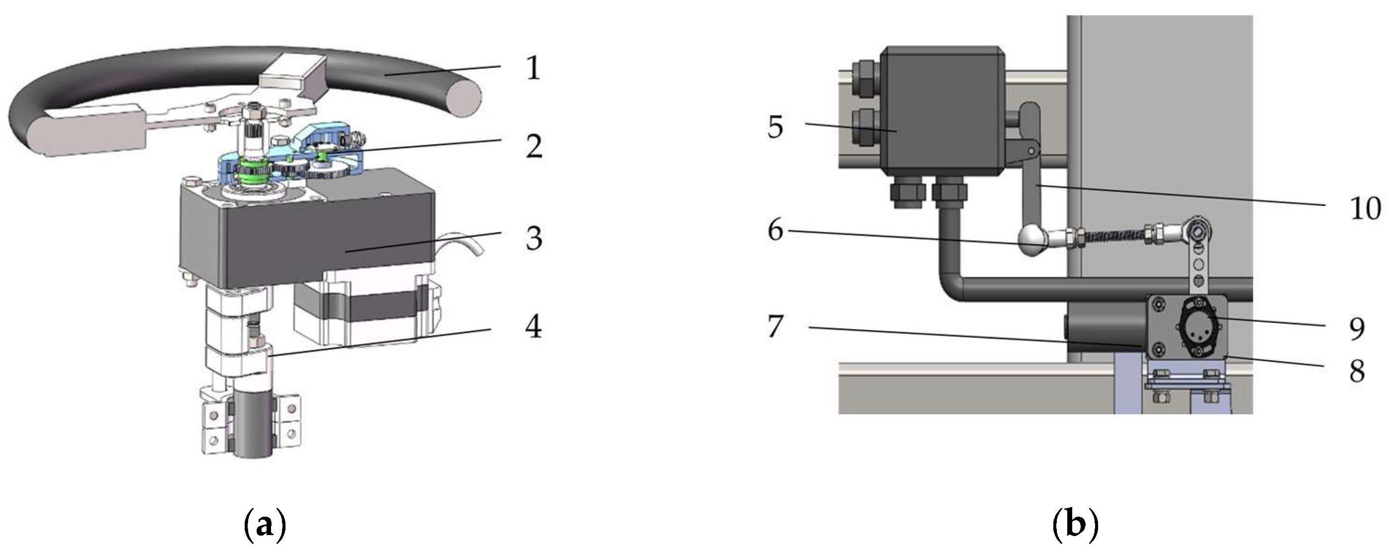
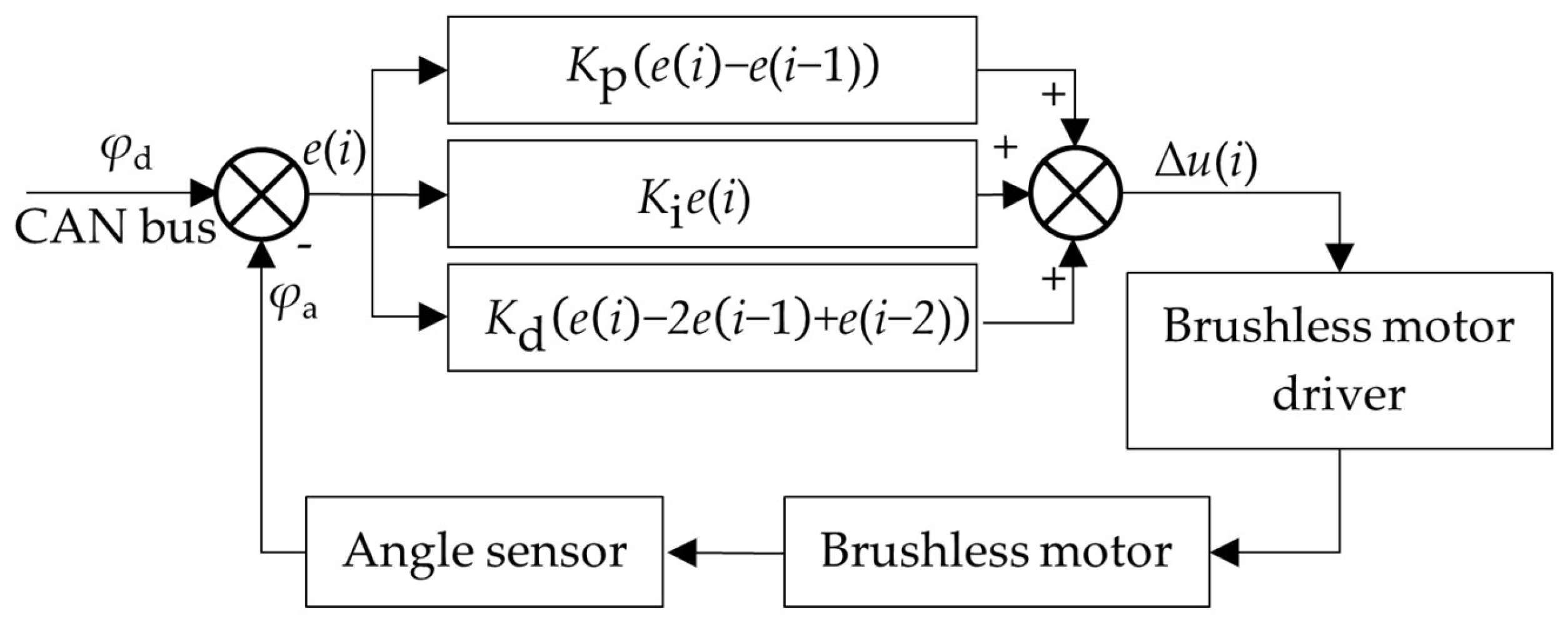
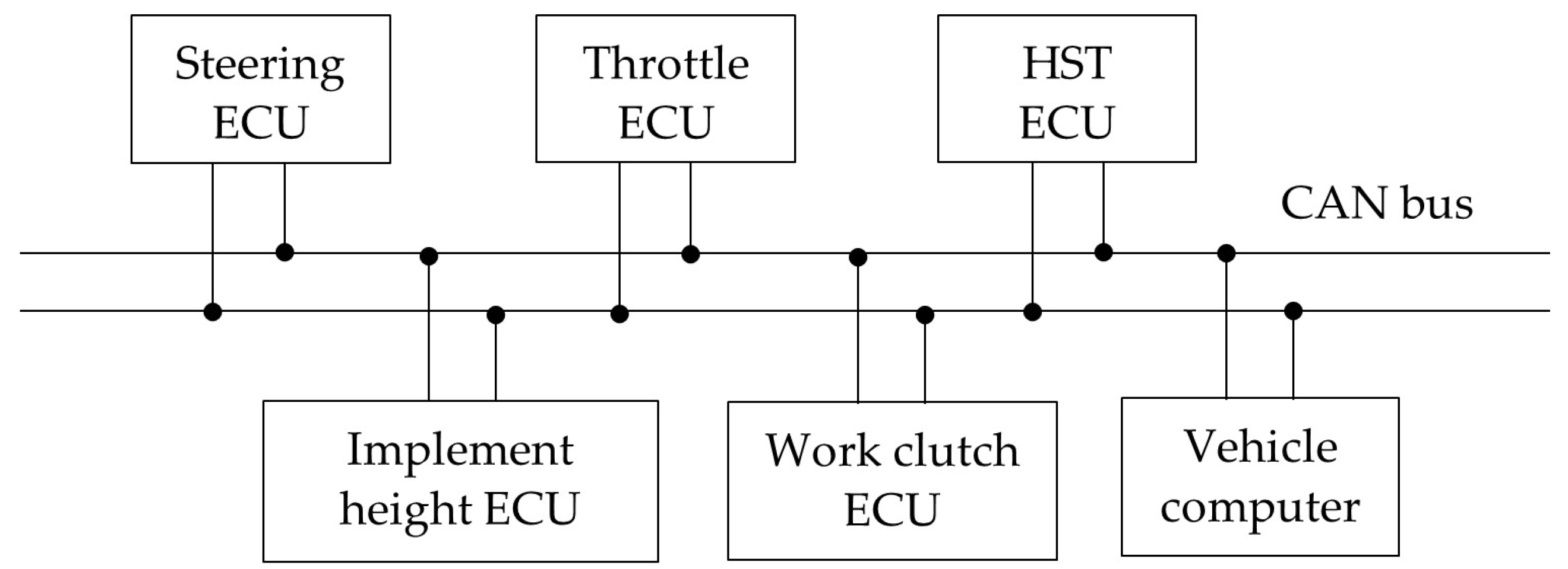
2.1. Realization of Automatic Operation
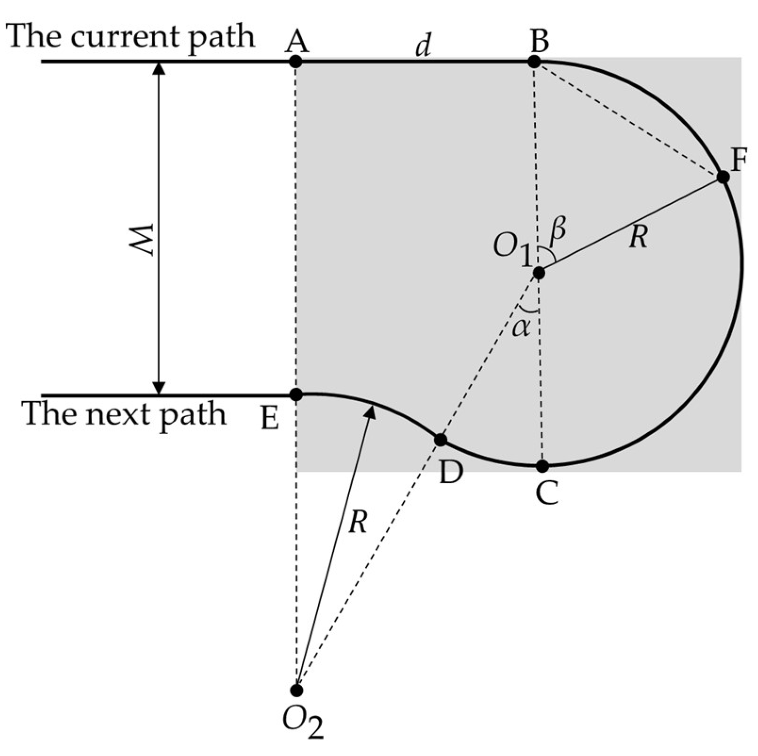
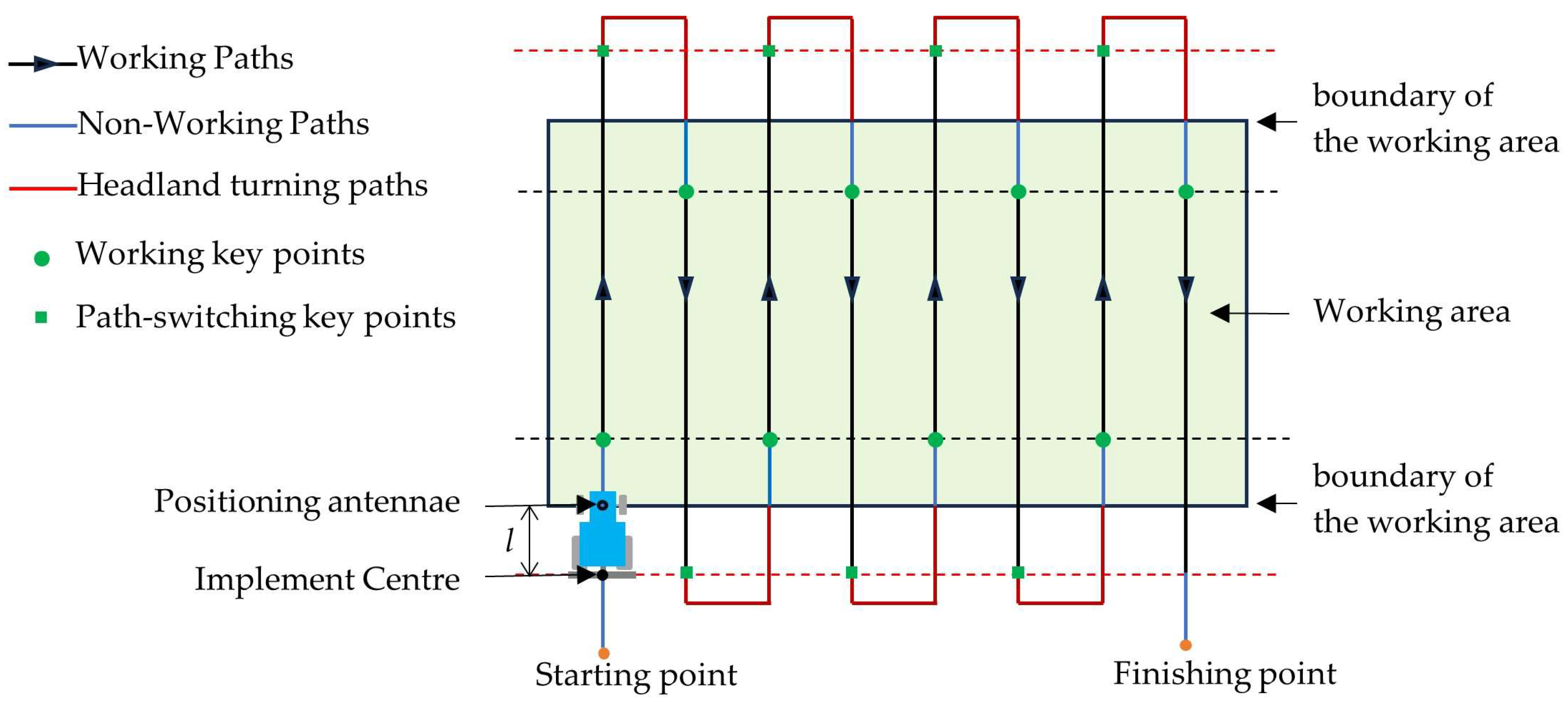
To achieve automatic control of rice transplanters, automatic devices were developed for steering, implement height adjustment, working clutch engagement, throttle regulation, and HST control. Considering the similarities in control methodologies among the automatic devices for implement height adjustment, working clutch engagement, throttle regulation, and HST control, this research presents the methods for achieving automated operation of rice transplanters, using the automatic implement height device and automatic steering device as illustrative examples.
This research designed an automatic steering device for rice transplanter steering control, designed to replace manual operation. As depicted in Figure 2a, the device primarily comprises a steering wheel, a brushless motor, a steering shaft, an angle sensor, and a reduction mechanism. The maximum torque applied to the steering shaft was measured as 9.6 N·m using a torque wrench. Consequently, a brushless motor manufactured by Ningbo Zhongda Leader Intelligent Transmission Co., Ltd. (Ningbo, China), with a voltage of 12 V, power of 100 W, torque of 12 N·m, and speed of 75 rpm, was selected to provide the required steering torque. Given that the rice transplanter is equipped with a closed-loop hydraulic power-assisted steering system, the rotation angle of the steering shaft exhibits a linear correlation with the steering angle of the steering wheel. Therefore, the angle sensor used to detect the steering angle is installed on the steering shaft rather than the front axle [28,29]. The maximum rotation angle of the steering shaft is 720°, whereas the detection range of the angle sensor is limited to 0–180°. To address this discrepancy, a reduction mechanism is incorporated between the steering shaft and the angle sensor.
As depicted in Figure 2b, the position of the hydraulic valve rotary arm determines the height of the implement. An automatic implement height device was developed to provide the torque necessary for automated control. This device comprises an angle sensor, a brushless motor, a reducer, and a tie rod mechanism. Both the angle sensor and the tie rod mechanism are coaxially coupled with the brushless motor. Driven by the brushless motor, the tie rod mechanism rotates to adjust the position of the hydraulic valve rotary arm, thereby regulating the height of the implement. The input shaft of the angle sensor rotates synchronously with the tie rod mechanism to measure the rotational position of the hydraulic valve rotary arm.
The control principle of the brushless motor utilized in automatic steering, implement height adjustment, and other automatic devices is illustrated in Figure 3. To achieve stable rotational angle control, an incremental PID algorithm is implemented. This algorithm computes the control signal ∆u(i) based on the difference e(i) between the commanded angle φd transmitted via the CAN bus and the actual steering angle φa feedback from the angle sensor. Subsequently, the control signal is transmitted to the brushless motor driver to regulate the operation of the brushless motor.
The incremental PID algorithm is shown in Equation (1).
u i = K p e i e ( i 1 ) + K i e ( i ) +   K d e i 2 e i 1 + e ( i 2 )
where Δu(i) is the increment of the current control cycle; Kp, Ki, and Kd are the proportional, integral, and differential coefficients, respectively; and e(i), e(i − 1), and e(i − 2) are the differences between the target and actual angles in the current, (i − 1)th, and (i − 2)th control cycles, respectively.
The rice transplanter is equipped with electronic control units (ECUs) for multiple automatic devices, including steering, throttle, HST, implement height, and working clutch. All these ECUs require receiving control instructions from the vehicle computer. To facilitate efficient data transmission among the ECUs, this research designed a CAN bus communication network, as depicted in Figure 4.
The vehicle computer processes RTK-GNSS positioning data to make control decisions for ECUs associated with steering control, implement height adjustment, working clutch operation, and other functions, which are subsequently transmitted via the CAN bus.

2.2. Path Planning

Path planning constitutes a critical component of rice transplanter operations within the field [30,31]. In this research, a path planning approach tailored for quadrilateral fields is proposed, considering parameters such as the width of the working area, the operational width of the rice transplanter, and its turning radius. This method establishes the coordinates of the starting and ending points, the linear equations, the working direction, and the headland turning pattern for each path.
The dual-antenna RTK-GNSS receiver is utilized to obtain the positions of point A1 (the starting point), point B1 (the ending point) of the first path, and boundary point G, thereby defining the target working area. For the purpose of path planning, the acquired raw map data are transformed into the Universal Transverse Mercator (UTM) coordinate system. Within the target working area, a line connecting points A1 and B1 serves as the baseline, with subsequent paths being generated parallel to this baseline. The spacing between adjacent paths is set to be equivalent to the working width of the rice transplanter. The final set of generated paths is presented in Figure 5.
The coordinates of points A1 and B1 are (EA1, NA1) and (EB1, NB1), respectively. The coordinates of the starting and ending points for the subsequent paths are presented as follows:
E A n = E A 1 + ( i 1 ) W cos θ N A n = N A 1 + ( i 1 ) W sin θ
E B n = E B 1 + ( i 1 ) W cos θ N B n = N B 1 + ( i 1 ) W sin θ
where i is the sequence number of the paths, { i | i N , 1     i     n } , and W is the working width of the rice transplanter.
The linear equations corresponding to each path are presented as follows:
y i = k x +   d i k = N B 1 N A 1 E B 1 E A 1 d i = E B i N A i N B i E A i E B i N A i
The coordinates of point G are (EG, NG). SGH denotes the width of the working area and is computed as follows:
S G H = k E G N G + d 1 k 2 + 1 + 0.5 W
The working direction is determined based on the relative position of the rice transplanter at point P prior to the commencement of navigation with respect to the target path. If the heading direction ψ of the rice transplanter does not exceed 90° relative to the A 1 B 1 , then the working direction is consistent with the vector A 1 B 1 ; otherwise, it is opposite to A 1 B 1 .
Given that the distance between point G and line segment A1B1 cannot be ensured to be an exact integer multiple of the working width W of the rice transplanter, the paths are categorized into standard paths and a residual path. The total number of paths, denoted as n, is computed as follows:
  n   = S GH W
where W is the working width of the rice transplanter.
The presence of the residual path is determined by the total number of working paths, the width of the working field, and the working width of the rice transplanter.
n ( S GH W ) = 0 ,   T h e   r e s i d u a l   p a t h   i s   n o t   p r e s e n t 1 ,   T h e   r e s i d u a l   p a t h   i s   p r e s e n t
The rice transplanter’s implement comprises six transplanting mechanisms, each of which can be independently controlled. During field operations, the number of activated transplanting mechanisms can be adjusted according to actual conditions. On standard paths, given the sufficient working width, all transplanting mechanisms will be activated to ensure efficient rice transplanting. On residual paths, however, as the path width may be less than the working width when all transplanting mechanisms are simultaneously activated, it is necessary to calculate the number of transplanting mechanisms, denoted as j, that need to be activated on the residual paths.
j = nW S GH m
where m is the spacing between adjacent transplanting implements.
Developing a rational approach for headland turning represents an effective strategy for enhancing work efficiency and reducing operational time [32,33]. Considering the substantial slip rate in rice paddies, the minimum turning radius of the rice transplanter is 1.5 m, and its working width is 1.8 m. As a result, the procedure for headland turning from the current path to the next one, as depicted in Figure 6, has been devised.
(1) Travel straight from point A to point B over the distance d. Owing to variations in slip rates across different regions, the values of d and the turning radius R during each headland turn are not fixed. The values of d and R are determined as follows:
  d = 4 R 2 W 2
  R = BF 2 sin β 2
(2) Execute a right turn from point B to point C. The current coordinates and heading are acquired through RTK-GNSS. At point C, the heading angle of the rice transplanter is 180° relative to its orientation at point B, and the distance between the two points is equal to 2R.
(3) Execute a left turn from point C to point D at an angle of α. The value of α is determined as follows:
  α =   cos 1 W 2 R
(4) Execute a circular motion from point D to point E with a radius of R, thereby completing the headland turn and transitioning into the next path.

2.3. An Operational Control Strategy Based on the FSM

The rice transplanter utilized in this research platform is front-wheel steered, with the GNSS positioning antenna mounted on the suspension above the front wheels to represent the position of the rice transplanter. Installing the GNSS positioning antenna at this location enables more precise tracking of the steering angle compared to other potential installation positions. However, a considerable distance exists between the implement and the positioning antenna, leading to a lag in the implement reaching the target working points relative to the antenna’s position. Consequently, it is impractical to control the working states of the rice transplanter based solely on the relative position of the positioning antenna to the boundaries of the working area. This research adopts an operational control strategy based on the FSM [34]. By defining key points and segmenting the working area into distinct paths, the rice transplanter operates in specific operational states for each type of path. This method significantly elevates the degree of automation for rice transplanters during field operations. The configuration of key points and path segmentation is illustrated in Figure 7.
By defining key points, the planned path is segmented into working paths, non-working paths, and headland turning paths. This ensures that the implement remains in the lowered and operational state within the working area and transitions to the raised and non-operational state outside the working area. The field working is thereby simplified into a process where the rice transplanter exhibits distinct operational states at different stages based on its positional information. In accordance with the actual working requirements of the rice transplanter and the fundamental control strategy of the FSM, the system states of the FSM are designed as presented in Table 2.
The navigation controller switches system states based on the position information provided by the positioning antenna to control the working state of the rice transplanter. The workflow is as follows:
After the navigation controller completes navigation path planning, it transmits the current position information to the FSM, enters the Start state, and initiates automatic alignment with the planned path. When the positioning antenna of the rice transplanter reaches the boundary of the working area while the implement has not yet arrived, the non-working path is triggered, and the system transitions into the S1 non-working state. In this state, the rice transplanter travels along the straight-line path, the implement is raised, and no transplanting work is performed.
As the rice transplanter continues to travel a distance l, the positioning antenna reaches a working key point, and the implement simultaneously arrives at the boundary of the working area. The working path is then triggered, and the system transitions into the S2 working state. In this state, the rice transplanter maintains straight-line travel, the implement is lowered to its working position, and transplanting work begins.
When the positioning antenna of the rice transplanter reaches a path-switching key point, the implement has just reached the opposite boundary of the working area. The headland turning path is triggered, and the system transitions into the S3 path-switching state. In this state, the implement is raised, and transplanting work is suspended. After completing the path-switching state, the system repeats the workflow from S1 to S3 until all paths are completed, transitioning into the Stop state. In the Stop state, the rice transplanter ceases movement, the implement remains in the raised position, and transplanting work halts.
During the navigation process, it is crucial to continuously evaluate the relative position of the rice transplanter with respect to the key points. As depicted in Figure 8, if the distance between the rice transplanter and the key point is less than the predefined threshold s, it is assumed that the rice transplanter has reached the key point. However, due to factors such as adverse weather conditions and obstructions, satellite navigation accuracy may be compromised, resulting in significant lateral errors. This can lead to situations where the rice transplanter has already reached the key point, yet the distance between the rice transplanter and the key point still exceeds the set threshold. In such cases, the following method is employed for determination.
The initial position of the rice transplanter is represented by point C′. When γ > 90°, the rice transplanter has not yet reached the working key point; when γ = 90°, the rice transplanter reaches the working key point, and the implement reaches the boundary of the working area; when γ < 90°, this indicates that the rice transplanter has passed the working key point, and the implement has entered the working area. Once the implement enters the working area, the position of the rice transplanter is indicated by point D′, which is determined through the calculation of δ. When δ < 90°, the rice transplanter remains within the working area; when δ = 90°, the rice transplanter reaches the path-switching key point, and the implement reaches the boundary at the opposite end of the working area; when δ > 90°, the rice transplanter has passed the path-switching key point, and the implement exits the working area. The formulas for calculating the values of γ and δ are as follows:
  γ = cos 1 C A A B C A A B
  δ =   cos 1 A B B D A B B D
The entire process of operational state transition for the rice transplanter is illustrated in Figure 9.

3. Results and Discussion

To evaluate the straight-line navigation performance of the rice transplanter and the accuracy of key point determination, a series of experiments were carried out on cement pavement and in fields in Hangzhou, China.

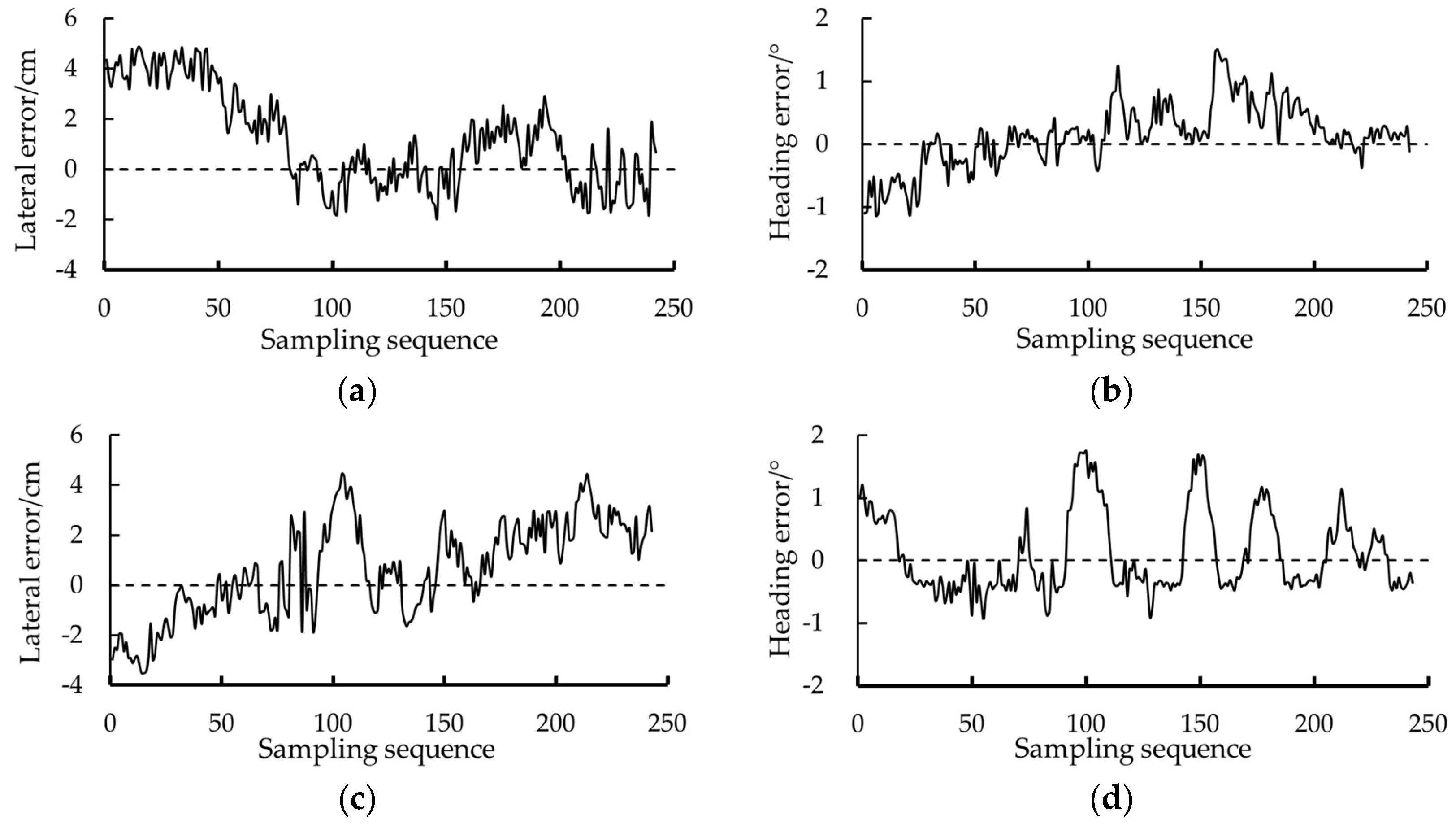
3.1. Navigation Performance Evaluation on the Cement Pavement

Figure 10 depicts the testing environment of the rice transplanter on the cement pavement. The coordinates of points A11 (732,110.262, 3,344,925.517), B11 (732,108.721, 3,344,946.837), and C1 (732,108.265, 3,344,929.075) were measured using the RTK-GNSS dual-antenna receiver. These coordinates were subsequently utilized to define the working area and generate the straight-line path.
As depicted in Figure 11, the rice transplanter initiates its journey from point P1 at a speed of 1 m/s, proceeds along path 1, and subsequently transitions to path 2 upon reaching the headland.
Table 3 presents the lateral and heading errors of the rice transplanter along two paths during the straight-line navigation phase on the cement pavement. The maximum lateral error of the rice transplanter on the cement pavement along two straight paths is 4.83 cm, while the maximum heading error is 1.13°. These maximum errors occur immediately after the rice transplanter completes a headland turn. The average lateral errors for the two paths are 1.57 cm and 1.20 cm, respectively. The average heading errors along the two straight paths are 0.25° and 0.26°, respectively. The RMS lateral errors along the two straight paths are 1.94 cm and 1.51 cm, respectively. The RMS heading errors along the two straight paths are 0.31° and 0.38°, respectively. Based on these results, it can be concluded that the rice transplanter exhibits excellent straight-line tracking performance on cement pavement.

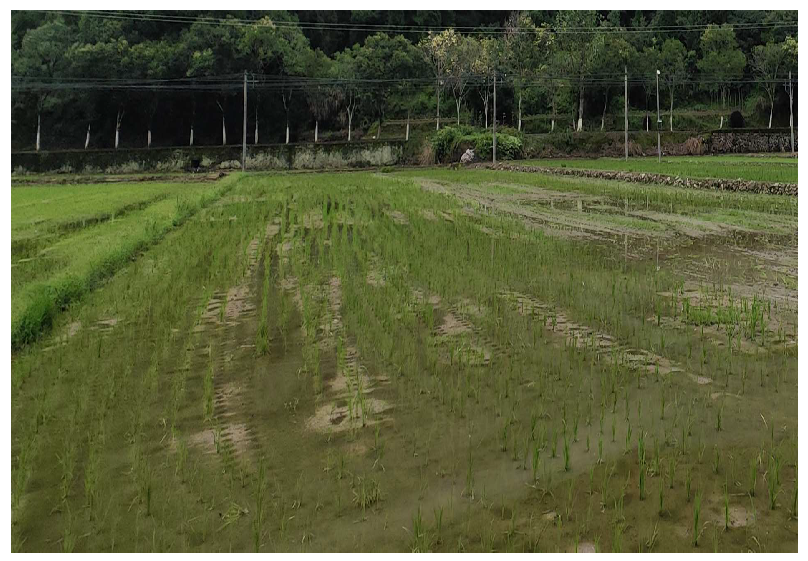
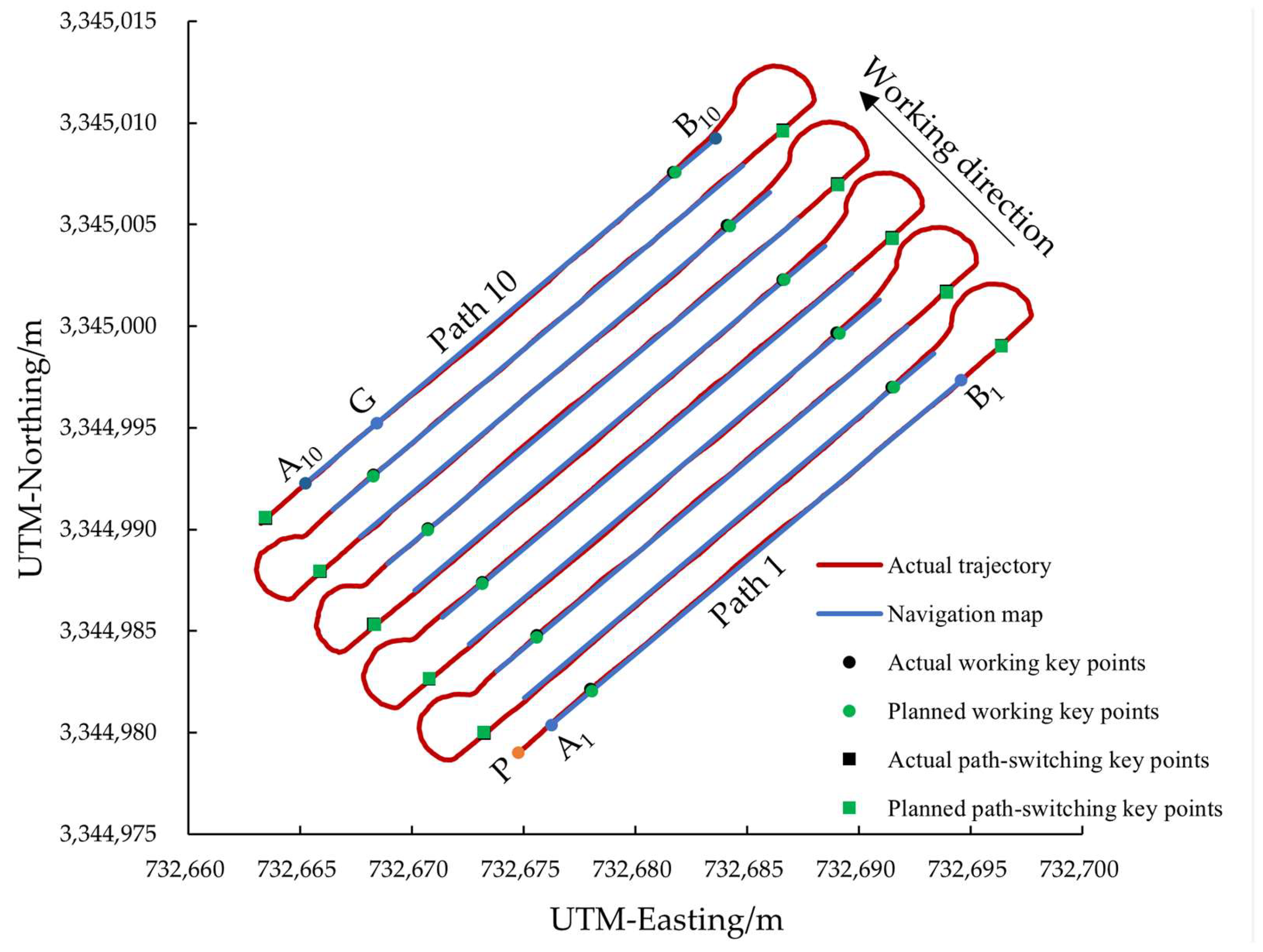
3.2. Navigation Performance Evaluation in the Field

To further evaluate the navigation performance of the rice transplanter equipped with the agricultural navigation system, a field trial was conducted in a field located in Hangzhou, Zhejiang Province. The experimental field is shown in Figure 12.
During the autonomous navigation process, Figure 13 illustrates the navigation map, actual trajectory in the field, planned key points, and actual key points of the rice transplanter. Within the experimental area, the coordinates of points A1 (732,676.253, 3,344,980.382), B1 (732,694.589, 3,344,997.341), and G (732,668.927, 3,344,995.671) were measured using the dual-antenna RTK-GNSS receiver. Based on these coordinates, the agricultural navigation system generated the initial path A1B1 as well as additional paths.
Under the guidance of the agricultural navigation system, the rice transplanter initiated its travel from point P and proceeded along path 1 at a speed of 1 m/s. Upon reaching the designated working key points, the implement was lowered to commence the transplanting process. When arriving at the path-switching key points, the implement was raised, the transplanting operation was suspended, and the headland turning procedure was executed to transition to the next path. This sequence of operations continued until all paths were completed. Throughout the entire operation, the lateral errors, heading errors, and errors in key point determination were systematically recorded and calculated.

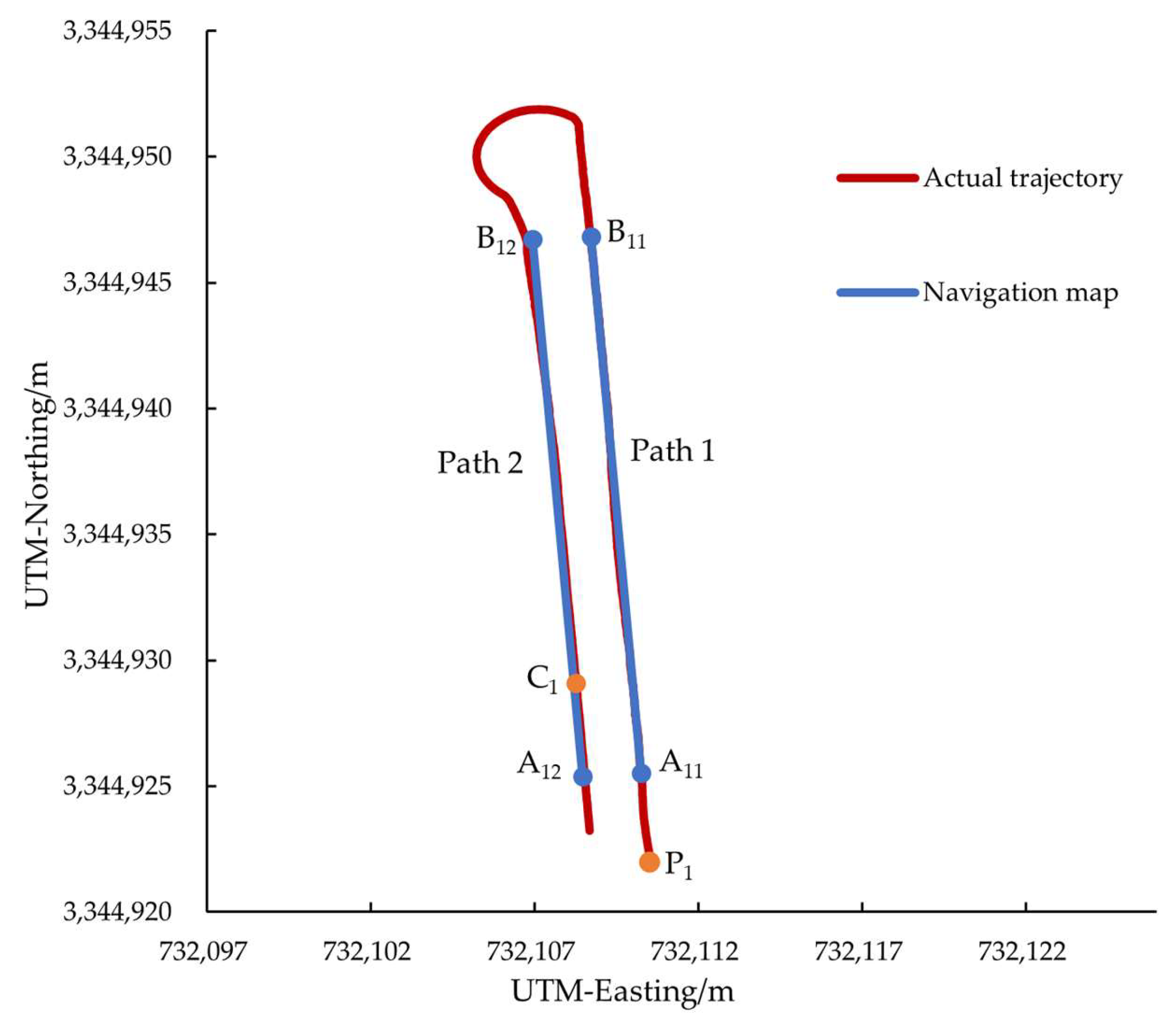
3.2.1. Evaluation of Straight-Line Path Navigation

Table 4 presents the lateral and heading errors of the rice transplanter along 10 paths during the straight-line navigation phase in the field. Among these, the maximum lateral error was 6.30 cm, while the maximum heading error was 2.25°. These maximum errors occurred after the rice transplanter completed a headland turn and entered the next path, which is an unavoidable phenomenon. The lateral RMS errors for each path were 2.22, 2.20, 1.99, 2.74, 3.12, 2.97, 2.62, 3.60, 2.78, and 3.27 cm, respectively. The heading RMS errors for each path were 0.64°, 0.51°, 0.65°, 0.63°, 0.60°, 0.40°, 0.58°, 0.68°, 0.53°, and 0.80°, respectively. The similar RMS values of lateral and heading errors across different paths indicate the satisfactory stability of the navigation system. Compared with previous studies, the error values obtained in this study are relatively smaller [35,36].
The lateral error and heading error for the straight-line path navigation of paths 2 and 3 are presented in Figure 14. For path 2, the maximum lateral error was 4.86 cm, and the maximum heading error was 1.51°. For path 3, the maximum lateral error was 4.46 cm, and the maximum heading error was 1.76°. Negative error values indicate that the rice transplanter deviated to the left relative to the planned path, whereas positive error values indicate deviation to the right.
Owing to the rice transplanter’s turning diameter being larger than its working width, during headland turns, it is necessary for the machine to first cross over the boundary of the next path prior to swinging back onto it. This results in the following two scenarios:
(1) The lateral error and heading error for the straight-line path navigation of path 2 are presented in Figure 14a,b. The next path is situated on the left side of the rice transplanter; upon completing a left headland turn, the rice transplanter will deviate to the right relative to the planned path. To minimize lateral error, the front of the rice transplanter is steered to the left, thereby generating a positive initial lateral error and a negative initial heading error. Following adjustments, the lateral and heading errors fluctuate near zero.
(2) The lateral error and heading error for the straight-line path navigation of path 3 are presented in Figure 14c,d. The next path is situated on the right side of the rice transplanter; upon completing a right headland turn, the rice transplanter will deviate to the left relative to the planned path. To minimize lateral error, the front of the rice transplanter is steered to the right, resulting in a positive initial lateral error and a negative initial heading error. Following adjustments, the lateral and heading errors fluctuate near zero.

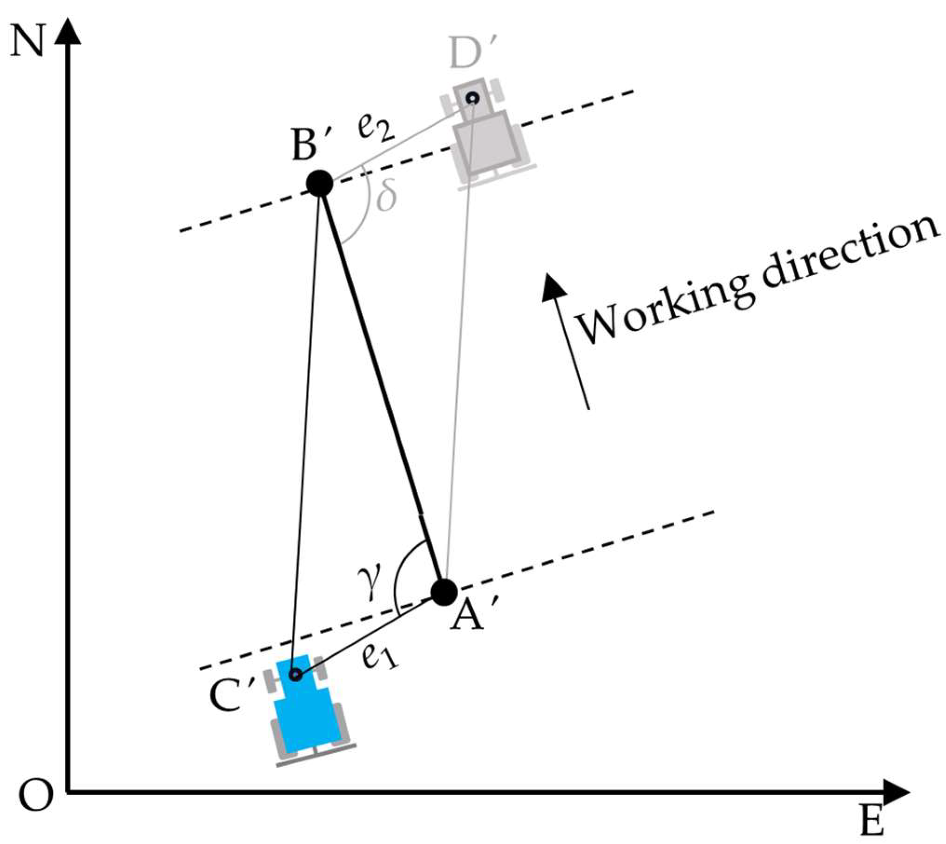
3.2.2. Evaluation of Key Points Determination

Previous studies have predominantly focused on the lateral and heading deviations of agricultural vehicles from the planned path during navigation, with limited attention to the precise control of the implement’s operational state [37,38]. In this study, key points are employed as the basis for switching the operational states of the rice transplanter. The agricultural navigation system identifies the key points of the FSM to control the working states of the rice transplanter. When the transplanter reaches the designated working key point of each path, the system transitions to the working state, lowering the implement to initiate the transplanting process. Upon reaching the designated path-switching key point of each path, the system transitions to the headland turning state, raising the implement, suspending the transplanting operation, and executing the headland turning procedure.
As presented in Table 5, the errors in working key points determined by agricultural navigation systems were 7.22 cm, 4.77 cm, 6.72 cm, 6.41 cm, 5.29 cm, 5.02 cm, 3.26 cm, 6.93 cm, 4.35 cm, and 5.86 cm, with an RMS error of 5.71 cm. For path-switching key points, the errors were 2.23 cm, 4.55 cm, 4.73 cm, 2.95 cm, 4.02 cm, 2.68 cm, 3.38 cm, 3.12 cm, 4.01 cm, and 3.89 cm, with an RMS error of 3.64 cm.
The key point error is defined as the discrepancy between the planned key point and the actual key point at which the rice transplanter completes the state transition during operation. A positive error indicates a delay in the navigation system’s determination, meaning that the actual key point occurs after the planned key point. Conversely, a negative error signifies an earlier determination by the navigation system, indicating that the actual key point occurs before the planned key point. Experimental results demonstrate that the errors at both working and path-switching key points are positive, with the errors at working key points generally being larger than those at path-switching key points. Figure 15 illustrates the determination of key points for paths 1 to 4, serving as an example for further analysis of the experimental results.
As the rice transplanter approaches the end of the current path, the lateral error has been maintained within a relatively small range through prior adjustments. When the rice transplanter reaches a point at a threshold distance from the path-switching key point, the agricultural navigation system transitions to the turning state slightly in advance. However, due to the inherent execution time of the automatic devices, the actual path-switching key point occurs slightly later than the planned path-switching key point, thereby introducing a delay in the state transition.
Following the completion of the headland turn, the rice transplanter experiences a relatively significant lateral error within a brief period, which precludes the lateral error from being reduced below the threshold s at the working key point. As a result, the agricultural navigation system transitions to the working state only after the rice transplanter has surpassed the planned working key point. Influenced by the inherent execution time of the automatic devices, the actual working key point exhibits a more pronounced lag relative to the actual path-switching key point.
To minimize the error in key point determination by the agricultural navigation system, future research could concentrate on the following two aspects: (1) optimizing the control algorithms of the automatic devices to reduce their response time and (2) expanding the width of the headland turning area by extending the straight-line distance after the rice transplanter reaches the path-switching key point. This adjustment would provide additional space for the rice transplanter to complete the headland turn and more effectively correct the lateral error prior to entering the next path.

4. Conclusions

This study developed an agricultural navigation system specifically designed for rice transplanters. The system integrates automated operation, path planning, and an operational control strategy based on the FSM. Unlike prior research that predominantly focused on lateral and heading deviations during navigation, this study defines key points to effectively switch the operational states of the rice transplanter, thereby significantly enhancing its level of automation. The rice transplanter equipped with this navigation system was tested on cement pavement and in field conditions, demonstrating reliable and stable navigation performance that meets the requirements for practical field operations.
The agricultural navigation system developed in this study is fully compatible with the 2ZGQ-6K ride-on high-speed type rice transplanter. For other rice transplanter models, minor adjustments to the automatic control device based on their mechanical structure are sufficient for complete integration, thereby offering significant practical implications. However, this study has certain limitations. Firstly, it is highly dependent on GNSS signals and lacks real-time environmental adaptability, which may affect system performance under obstructed or dynamic field conditions. Consequently, under conditions of occlusion or dynamic field environments, the system’s performance may be compromised. Secondly, the execution time of the automatic device significantly influences the determination of key points.
Future research will prioritize the optimization of the control algorithms for automatic devices and operational control strategies, as well as the integration of advanced sensors, including LiDAR and stereo cameras, to enhance positioning accuracy and environmental perception capabilities of the agricultural navigation systems. Additionally, efforts will be made to improve the universality of this agricultural navigation system for application to a broader range of agricultural wheeled vehicles. This research lays the groundwork for the development of smarter and more efficient agricultural machinery and contributes to the advancement of modern agriculture.

Author Contributions

Conceptualization, X.Y. and Z.Z.; methodology, Z.Z. and Y.Y.; software, X.Y.; validation, J.D. and Y.L.; formal analysis, Z.Z. and J.Z.; investigation, Y.Y. and J.Z.; resources, X.Y.; data curation, X.Y. and Z.Z.; writing—original draft preparation, Z.Z.; writing—review and editing, X.Y. and Z.Z.; visualization, J.Z.; supervision, X.Y.; project administration, Y.L.; funding acquisition, X.Y. All authors have read and agreed to the published version of the manuscript.

Funding

This research was funded by National Natural Science Foundation of China (Grant No. 32171910); the National Key Research and Development Program of China (Grant No. 2021YFD2000502); Key R&D Program of Shandong Province, China (Grant No. 2022SFGC0201); Zhejiang province agricultural machinery research, manufacturing and application integration project (Grant No. 2023-YT-06).

Institutional Review Board Statement

Not applicable.

Data Availability Statement

The original contributions presented in the study are included in the article; further inquiries can be directed to the corresponding author.

Conflicts of Interest

The authors declare no conflicts of interest.

References

  1. Zhang, D.; Qi, H.; Guo, X.; Sun, H.; Min, J.; Li, S.; Hou, L.; Lv, L. Integration of UAV Multispectral Remote Sensing and Random Forest for Full-Growth Stage Monitoring of Wheat Dynamics. Agriculture 2025, 15, 353. [Google Scholar] [CrossRef]
  2. Cui, B.; Cui, X.; Wei, X.; Zhu, Y.; Ma, Z.; Zhao, Y.; Liu, Y. Design and Testing of a Tractor Automatic Navigation System Based on Dynamic Path Search and a Fuzzy Stanley Model. Agriculture 2024, 14, 2136. [Google Scholar] [CrossRef]
  3. Chai, S.; Wen, M.; Li, P.; Zeng, Z.; Tian, Y. DCFA-YOLO: A Dual-Channel Cross-Feature-Fusion Attention YOLO Network for Cherry Tomato Bunch Detection. Agriculture 2025, 15, 271. [Google Scholar] [CrossRef]
  4. Lei, G.; Zhou, S.; Zhang, P.; Xie, F.; Gao, Z.; Shuang, L.; Xue, Y.; Fan, E.; Xin, Z. Stability Control of the Agricultural Tractor-Trailer System in Saline Alkali Land: A Collaborative Trajectory Planning Approach. Agriculture 2025, 15, 100. [Google Scholar] [CrossRef]
  5. Ren, H.; Wu, J.; Lin, T.; Yao, Y.; Liu, C. Research on an Intelligent Agricultural Machinery Unmanned Driving System. Agriculture 2023, 13, 1907. [Google Scholar] [CrossRef]
  6. Zhang, Y.; Song, Y.; Lu, F.; Zhang, D.; Yang, L.; Cui, T.; He, X.; Zhang, K. Design and Experiment of Greenhouse Self-Balancing Mobile Robot Based on PR Joint Sensor. Agriculture 2023, 13, 2040. [Google Scholar] [CrossRef]
  7. Saha, S.; Morita, T.; Ospina, R.; Noguchi, N. A Vision-Based Navigation System for an Agricultural Autonomous Tractor. IFAC-PapersOnLine 2022, 55, 48–53. [Google Scholar] [CrossRef]
  8. Utamima, A.; Reiners, T. Navigating Route Planning for Multiple Vehicles in Multifield Agriculture with a Fast Hybrid Algorithm. Comput. Electron. Agric. 2023, 212, 108021. [Google Scholar] [CrossRef]
  9. Liu, Y.; Wang, J.; Shi, Y.; He, Z.; Liu, F.; Kong, W.; He, Y. Unmanned Airboat Technology and Applications in Environment and Agriculture. Comput. Electron. Agric. 2022, 197, 106920. [Google Scholar] [CrossRef]
  10. Ünal, İ.; Topakci, M. Design of a Remote-Controlled and GPS-Guided Autonomous Robot for Precision Farming. Int. J. Adv. Robot. Syst. 2015, 12, 194. [Google Scholar] [CrossRef]
  11. Xie, K.; Zhang, Z.; Zhu, S. Enhanced Agricultural Vehicle Positioning through Ultra-Wideband-Assisted Global Navigation Satellite Systems and Bayesian Integration Techniques. Agriculture 2024, 14, 1396. [Google Scholar] [CrossRef]
  12. Ding, F.; Zhang, W.; Luo, X.; Zhang, Z.; Wang, M.; Li, H.; Peng, M.; Hu, L. Design and Experiment for Inter-Vehicle Communication Based on Dead-Reckoning and Delay Compensation in a Cooperative Harvester and Transport System. Agriculture 2022, 12, 2052. [Google Scholar] [CrossRef]
  13. Marucci, A.; Colantoni, A.; Zambon, I.; Egidi, G. Precision Farming in Hilly Areas: The Use of Network RTK in GNSS Technology. Agriculture 2017, 7, 60. [Google Scholar] [CrossRef]
  14. Wang, G.; Han, Y.; Chen, J.; Wang, S.; Zhang, Z.; Du, N.; Zheng, Y. A GNSS/INS Integrated Navigation Algorithm Based on Kalman Filter. IFAC-PapersOnLine 2018, 51, 232–237. [Google Scholar] [CrossRef]
  15. Aravindvas, V.; Srinivas, U.; Rayudu, M.V.; Subhash, T.; Prashanth, B.N. Design and Development of Sensor Based Automatic Steering Control System for Automobiles. Mater. Today Proc. 2021, 46, 5176–5181. [Google Scholar] [CrossRef]
  16. Yang, Y.; Zhang, G.; Zha, J.; Li, Y.; Zhang, T.; Chen, L. Design of Automatic Steering System Based on Direct Connection of DC Motor and Full Hydraulic Steering Gear. Trans. Chin. Soc. Agric. Mach. 2020, 51, 44–54. [Google Scholar] [CrossRef]
  17. Bo, H.; Liang, W.; Yuefeng, D.; Zhenghe, S.; Enrong, M.; Zhongxiang, Z. Design and Experiment on Integrated Proportional Control Valve of Automatic Steering System. IFAC-PapersOnLine 2018, 51, 389–396. [Google Scholar] [CrossRef]
  18. Liu, J.; Tan, J.; Mao, E.; Song, Z.; Zhu, Z. Proportional Directional Valve Based Automatic Steering System for Tractors. Front. Inf. Technol. Electronic. Eng. 2016, 17, 458–464. [Google Scholar] [CrossRef]
  19. Ljungqvist, O.; Evestedt, N.; Axehill, D.; Cirillo, M.; Pettersson, H. A Path Planning and Path-Following Control Framework for a General 2-Trailer with a Car-like Tractor. J. Field Rob. 1377, 36, 1345. [Google Scholar] [CrossRef]
  20. Zhou, J.; He, Y. Research Progress on Navigation Path Planning of Agricultural Machinery. Trans. Chin. Soc. Agric. Mach. 2021, 52, 1–14. [Google Scholar] [CrossRef]
  21. Graf Plessen, M.M. Partial Field Coverage Based on Two Path Planning Patterns. Biosyst. Eng. 2018, 171, 16–29. [Google Scholar] [CrossRef]
  22. Utamima, A.; Reiners, T.; Ansaripoor, A.H. Optimisation of Agricultural Routing Planning in Field Logistics with Evolutionary Hybrid Neighbourhood Search. Biosyst. Eng. 2019, 184, 166–180. [Google Scholar] [CrossRef]
  23. Utamima, A.; Reiners, T.; Ansaripoor, A.H. Evolutionary Estimation of Distribution Algorithm for Agricultural Routing Planning in Field Logistics. Procedia Comput. Sci. 2019, 161, 560–567. [Google Scholar] [CrossRef]
  24. Holpp, M.; Kroulik, M.; Kviz, Z.; Anken, T.; Sauter, M.; Hensel, O. Large-Scale Field Evaluation of Driving Performance and Ergonomic Effects of Satellite-Based Guidance Systems. Biosyst. Eng. 2013, 116, 190–197. [Google Scholar] [CrossRef]
  25. Meng, Z.; Liu, H.; Wang, H.; Fu, W. Optimal Path Planning for Agricultural Machinery. Trans. Chin. Soc. Agric. Mach. 2012, 43, 147–152. [Google Scholar] [CrossRef]
  26. Cariou, C.; Gobor, Z.; Seiferth, B.; Berducat, M. Mobile Robot Trajectory Planning Under Kinematic and Dynamic Constraints for Partial and Full Field Coverage. J. Field Robot. 2017, 34, 1297–1312. [Google Scholar] [CrossRef]
  27. Boryga, M.; Kołodziej, P.; Gołacki, K. Application of Polynomial Transition Curves for Trajectory Planning on the Headlands. Agriculture 2020, 10, 144. [Google Scholar] [CrossRef]
  28. Wu, C.; Wang, D.; Chen, Z.; Song, B.; Yang, L.; Yang, W. Autonomous driving and operation control method for SF2104 tractors. Trans. Chin. Soc. Agric. Eng. 2020, 36, 42–48. [Google Scholar] [CrossRef]
  29. An, G.; Yu, C.; Du, J.; Yin, X.; Ni, Y.; Jin, C. Development of the Electric Automatic Steering System for Agricultural Vehicles. Int. J. Agric. Biol. Eng. 2024, 17, 209–214. [Google Scholar] [CrossRef]
  30. Liu, L.; Wang, X.; Liu, H.; Li, J.; Wang, P.; Yang, X. A Full-Coverage Path Planning Method for an Orchard Mower Based on the Dung Beetle Optimization Algorithm. Agriculture 2024, 14, 865. [Google Scholar] [CrossRef]
  31. Yang, S.; Zhang, E.; Liu, Y.; Du, J.; Yin, X. ZPTM: Zigzag Path Tracking Method for Agricultural Vehicles Using Point Cloud Representation. Sensors 2025, 25, 1110. [Google Scholar] [CrossRef] [PubMed]
  32. Zhou, K.; Jensen, A.L.; Bochtis, D.D.; Sørensen, C.G. Quantifying the Benefits of Alternative Fieldwork Patterns in a Potato Cultivation System. Comput. Electron. Agric. 2015, 119, 228–240. [Google Scholar] [CrossRef]
  33. Wei, S.; Li, S.; Zhang, M.; Ji, Y.; Xiang, M.; Li, M. Automatic navigation path search and turning control of agricultural machinery based on GNSS. Trans. Chin. Soc. Agric. Eng. 2017, 33, 70–77. [Google Scholar] [CrossRef]
  34. Zhou, Z.; Yu, X.; Liang, L.; Xiang, Y.; Chen, Y.; Luo, X. Design and Experiment of Translation and Line Feed Navigation Control System for Four Wheel Steering Sprayer. Trans. Chin. Soc. Agric. Mach. 2023, 54, 68–78. [Google Scholar] [CrossRef]
  35. Huang, S.; Pan, K.; Wang, S.; Zhu, Y.; Zhang, Q.; Su, X.; Yu, H. Design and Test of an Automatic Navigation Fruit-Picking Platform. Agriculture 2023, 13, 882. [Google Scholar] [CrossRef]
  36. Yang, T.; Jin, C.; Ni, Y.; Liu, Z.; Chen, M. Path Planning and Control System Design of an Unmanned Weeding Robot. Agriculture 2023, 13, 2001. [Google Scholar] [CrossRef]
  37. Baltazar, J.d.A.; Coelho, A.L.d.F.; Valente, D.S.M.; de Queiroz, D.M.; Villar, F.M.d.M. Development of a Robotic Platform with Autonomous Navigation System for Agriculture. AgriEngineering 2024, 6, 3362–3374. [Google Scholar] [CrossRef]
  38. Zhai, W.; Wang, D.; Chen, Z.; Dong, L.; Zhao, X.; Wu, C. Autonomous operation path planning method for unmanned agricultural machinery. Trans. Chin. Soc. Agric. Eng. 2021, 37, 1–7. [Google Scholar] [CrossRef]
Figure 1. Composition of the test platform.
Agriculture 15 01125 g001
Figure 2. Automatic steering device and automatic implement height device: (a) Automatic steering device: 1, steering wheel; 2, angle sensor and reduction mechanism; 3, brushless motor; 4, steering shaft. (b) Automatic implement height device: 5, hydraulic valve; 6, tie rod mechanism; 7, brushless motor; 8, reducer; 9, angle sensor; 10, hydraulic valve rotary arm.
Agriculture 15 01125 g002
Figure 3. Brushless motor control principle.
Agriculture 15 01125 g003
Figure 4. CAN bus communication network.
Agriculture 15 01125 g004
Figure 5. Path generation.
Agriculture 15 01125 g005
Figure 6. Procedure for headland turning from the current path to the next one.
Agriculture 15 01125 g006
Figure 7. The FSM key points setting and path segmentation.
Agriculture 15 01125 g007
Figure 8. Key point determination for the FSM: A′, the working key point; B′, the path-switching key point; C′ and D′, the position of rice transplanter; γ, the angle between C A and A B ; δ, the angle between A B and B D . e1, the distance between the rice transplanter and the working key point. e2, the distance between the rice transplanter and the path-switching key point.
Agriculture 15 01125 g008
Figure 9. Flowchart for switching operational states.
Agriculture 15 01125 g009
Figure 10. Experimental environment on the cement pavement.
Agriculture 15 01125 g010
Figure 11. Navigation map and actual trajectory on the cement pavement.
Agriculture 15 01125 g011
Figure 12. Experimental field.
Agriculture 15 01125 g012
Figure 13. Navigation map and actual trajectory in the field.
Agriculture 15 01125 g013
Figure 14. The lateral errors and heading errors for the straight-line path navigation of paths 2 and 3: (a) Lateral error of path 2; (b) Heading error of path 2; (c) Lateral error of path 3; (d) Heading error of path 3.
Agriculture 15 01125 g014
Figure 15. Determination of key points for path 1 to path 4.
Agriculture 15 01125 g015
Table 1. Main technical parameters of the Kubota 2ZGQ-6K ride-on high-speed rice transplanter.
Technical ParametersValue
Length × width × height (mm)3275 × 2265 × 2605
Turning radius (mm)1500
Row spacing (mm)300
Number of working rows6
Transplanting depth (mm)10~52
Speed (km·h−1)0~5.6
Engine power (kW)16.1
Table 2. The system states of the FSM.
System StatesOperational StatesDriving ControlImplement Control
StartStart stateInitializationU, N
S1Non-working stateStraight aheadU, N
S2Working stateStraight aheadD, Y
S3Path-switching state Headland turningU, N
StopWork completion stateCessationU, N
Note: U indicates implement lifting, D denotes implement lowering, Y represents the rice transplanter performing transplanting, and N indicates that the rice transplanter is not performing transplanting.
Table 3. Lateral error and heading error on the cement pavement.
PathLateral Error/cmHeading Error/°
Average
Values
Maximum ValuesRMSAverage
Values
Maximum ValuesRMS
Path 11.574.831.940.251.030.31
Path 21.203.471.510.261.130.38
Table 4. Lateral errors and heading errors for the straight-line path navigation in the field.
PathLateral Error/cmHeading Error/°
Average
Values
Maximum ValuesRMSAverage
Values
Maximum ValuesRMS
Path 11.596.222.220.541.680.64
Path 21.704.862.200.391.510.51
Path 31.674.461.990.521.760.65
Path 42.275.232.740.432.250.63
Path 53.036.183.120.481.700.60
Path 62.315.972.970.301.280.40
Path 72.274.992.620.471.660.58
Path 83.166.303.600.502.090.68
Path 92.485.572.780.431.660.53
Path 102.896.093.270.592.130.80
Table 5. Errors in key points determined by the agricultural navigation system.
Path12345678910
Errors in working key points /cm7.224.776.726.415.295.023.266.934.355.86
Errors in path-switching key points /cm2.234.554.732.954.022.683.383.124.013.89
Disclaimer/Publisher’s Note: The statements, opinions and data contained in all publications are solely those of the individual author(s) and contributor(s) and not of MDPI and/or the editor(s). MDPI and/or the editor(s) disclaim responsibility for any injury to people or property resulting from any ideas, methods, instructions or products referred to in the content.

