Article

Optimizing Active Disturbance Rejection Control for a Stubble Breaking and Obstacle Avoiding Control System

Faculty of Modern Agricultural Engineering, Kunming University of Science and Technology, Kunming 650500, China
*
Author to whom correspondence should be addressed.
Agriculture 2024, 14(5), 786; https://doi.org/10.3390/agriculture14050786
Submission received: 9 April 2024 / Revised: 14 May 2024 / Accepted: 15 May 2024 / Published: 20 May 2024
(This article belongs to the Section Agricultural Technology)

Abstract

:
In order to improve the obstacle avoidance control performance and anti-interference ability of a stubble breaking device of a no-tillage planter, a back-propagation neural network (BPNN)-optimized fuzzy active disturbance rejection control (ADRC) controller was designed to optimize the control performance of a servo motor. Firstly, a negative feedback mathematical model was established for the obstacle avoidance control system. Then, the nonlinear state error feedback (NLSEF) parameters in the fuzzy ADRC were intelligently optimized by the BPNN algorithm. In this way, a fuzzy ADRC controller based on BPNN optimization was formed to optimize the control process of a servo motor. Matlab/Simulink (R2022b) was used to complete the simulation model design and parameter adjustment. Consequently, the response time was 0.089 s using the BPNN fuzzy ADRC controller, which was shorter than the 0.303 s of the ADRC controller and the 0.100 s of the fuzzy ADRC controller. The overshoot was 0.1% using a BPNN fuzzy ADRC controller, which was less than the 2% of the ADRC controller and the 1% of the fuzzy ADRC controller. After noise signal interference was introduced into the control system, the regression steady state time of the BPNN fuzzy ADRC controller was 0.22 s, which was shorter than the 0.56 s of the ADRC controller and the 0.45 s of the fuzzy ADRC controller. A hardware-in-the-loop simulation experimental platform of the obstacle avoidance control system was constructed. The experiment results show that the servo motor control system has a fast dynamic response, small steady-state error and strong anti-interference ability for obstacle avoidance at the target height. Then, the control system error was within the allowable range. The servo motor control effect of the BPNN fuzzy ADRC was better than the ADRC and fuzzy ADRC. This optimized servo motor control method can provide a reference for improving the obstacle avoidance control effect problem of no-tillage seeders in stubble breaking operations on rocky desertification areas.

1. Introduction

Southwest is one of the three major maize production zones of China [1], accounting for about 10% of the nation’s planted area in 2022 [2]. However, the karst landform in this region is the largest area of rocky desertification in the world and the most profoundly affected by disasters [3], with an exposed area of about 50 million hectares [1]. The food security of the southwest region is seriously affected by the thin soil layer, infertile soil, and poor water and fertilizer retention capacity of arable land [4]. Conservation tillage is an advanced farming technique to improve soil fertility and drought resistance. It aims to achieve stable yields and increase income by applying no-till or minimal tillage and covering the ground with crop straw to reduce wind and water erosion [5,6]. Moreover, an achieving stable yield and increased yield in the southwest maize-growing region are crucial to implement conservation tillage technology. However, when the no-till seeding operation is implemented in this region, the stubble breaking corrugated disc cutter is susceptible to damage from exposed bedrock and gravel in the field. This issue seriously affects the working performance and lifespan of no-till seeders. Therefore, researching the autonomous obstacle avoidance control of a no-till planter stubble breaking operation is of great practical significance.
Nevertheless, the no-till seeding operation in the southwest rocky desertification area is characterized by complex working conditions and large disturbances. This presents higher requirements for the robustness and adaptiveness of the stubble breaking operation obstacle avoidance control system. To meet these control requirements, Han Jingqing [7] proposed the active disturbance rejection control method based on PID control. This method retains the advantages of PID control and can be adapted to nonlinear systems to overcome unknown disturbances. Tian et al. [8] used the dynamic adjustment ability of fuzzy rules to optimize the discovery probability parameters in the traditional cuckoo search. They then applied the optimized cuckoo search to intelligently search for the ten parameters in ADRC to find the best combination. Furthermore, it was found that under the condition of eliminating the need for manual tuning of parameters, the control effect of the controller could still meet the requirements of use. Wang et al. [9] combined active disturbance rejection technology and a load torque observer in the speed loop of a permanent magnet synchronous motor. They designed an improved second-order active disturbance rejection controller to effectively enhance the dynamic and static characteristics of the speed control system. Li et al. [10] designed a radial basis function (RBF) neural network and sought optimal solutions for ADRC parameters in real time. This approach addressed the issue of complicated ADRC parameter settings. Qu et al. [11] combined ADRC with sliding mode control without the need for establishing an accurate mathematical model of the permanent magnet synchronous motor. This approach exhibited good anti-interference performance while reducing the buffeting effect caused by sliding mode control. However, it only applied the improved technique to the current loop, while the speed loop still used traditional PI control. Tian et al. [12] proposed an adaptive control method that can compensate for changes in controlled object parameters and modify control parameters in real time. Li et al. [13] applied ADRC to the clamping force control system, and proposed and implemented a CPSO–ADRC system by optimizing the key parameters of an ordinary self-resistant controller using a chaotic particle swarm algorithm.
Many scholars at home and abroad combine different algorithms with ADRC to improve the response accuracy of the controlled system, which requires a large number of manually adjusted parameters and complicated parameter settings. There is also little research on the parameter settings of the nonlinear-state error feedback device in ADRC. Usually, empirical methods are used to try and improve the current methods, resulting in poor control effects of the controller.
In order to realize the rapid response of the servo motor and improve the interference immunity during the obstacle avoidance process of the stubble breaking device, the obstacle avoidance process was studied, a negative feedback mathematical model of the obstacle avoidance control system was established, and a fuzzy ADRC controller for the servo motor speed was designed. The BPNN algorithm with an independent learning ability is introduced to optimize the parameters of the nonlinear-state error feedback device in fuzzy ADRC, which improves the stability and immunity of the servo motor control system.

2. Materials and Methods

2.1. System Structure Composition and Working Principle

2.1.1. System Structure Composition

The overall structure of the obstacle avoidance control system of the stubble breaking device is shown in Figure 1, which mainly consists of four parts: a mechanical body, an input module, a control module, and an actuator. The mechanical body includes a traction frame, profiling wheel mechanism, and guide wheel. The input module is composed of an ultrasonic sensor and an A/D converter. The control module includes a PLC and servo driver. The actuator includes a servo motor, synchronous belt, screw slide module, and stubble breaker.

2.1.2. Working Principle of the Obstacle Avoidance Device

The stubble breaking device is part of a no-till seeder and is pulled by a tractor. The ultrasonic sensor is installed on the bottom plate of the stubble breaking device above the center line of the two stubble breaking knives to detect its height from the ground in real time. When the ultrasonic sensor detects that the distance to the surface is less than the set surface distance, it is approximately considered that there are obstacles such as larger stones and rocks on the surface at this time. The ultrasonic sensor transmits the detected signal to the main control PLC through the A/D converter, and the PLC outputs the signal to the servo driver to drive the servo motor, driving the screw slider in the screw slide module to move up. The stubble knives are connected to realize the improvement of the stubble breaker. When the ultrasonic sensor detects that the distance to the ground is equal to the set surface distance, it is considered that there are no obstacles on the ground at this time, and the PLC sends instructions to control the servo motor to lower the stubble-breaking knife to the surface height, and the stubble breaking operation can be carried out normally, thereby realizing the autonomous obstacle avoidance control process of the stubble breaking device.

2.1.3. Hardware System Design

In the hardware design of the stubble breaking obstacle avoidance control system, the maximum height that needs to be detected is 400 mm from the bottom plate of the stubble breaking device to the ground. Therefore, the ultrasonic sensor is selected as the KS103 model, and its measurement range is 100–5000 mm. It can use a 485 mm communication interface to connect with the main controller. The main controller chosen is the Mitsubishi FX3U-16MT PLC (MITSUBISHI ELECTRIC, Dalian, China), which is a third-generation PLC of Mitsubishi, with a built-in independent three-axis 100 kHz positioning function (transistor output), and high-speed processing capability, suitable for obstacle avoidance control system requirements. The screw slide table is Yuanuo 125, and its effective stroke is 200 mm, which meets the obstacle avoidance stroke range of the stubble breaking device, and the vertical load of 80 kg, which is larger than the total weight of 30 kg of the stubble cutter and connecting rod. According to the load of stubble breaker and the parameter requirements of the screw, the Lichuan LCMT-04L2NB-60M0133C DC servo motor (LiCHUAN ELECTRICAL, Shenzhen, China) is chosen, which is equipped with the Lichuan LCDA4 04B202-LB632 servo driver (LiCHUAN ELECTRICAL, Shenzhen, China).

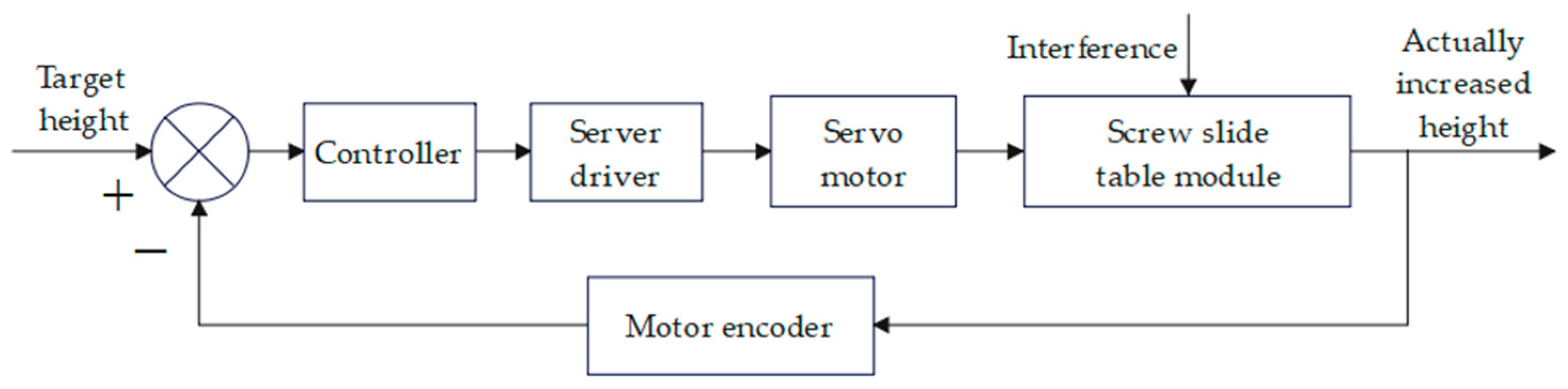
2.2. Obstacle Avoidance Control System Modeling

The obstacle avoidance control system primarily relies on ultrasonic sensors as input signals. These sensors detect obstacles like exposed bedrock and gravel in the field, and the height information of the circular corrugated cutter in relation to the obstacles is sent to the controller. Based on the desired control requirements, the controller adjusts the speed and direction of the DC servo motor, which in turn drives the target control requirements and the circular corrugated cutter to reach the target height using the timing belt and screw slide module. This autonomous obstacle avoidance is then achieved, and a displacement sensor installed above the circular corrugated cutter provides real-time feedback on the rise height. This creates a closed-loop negative feedback control system for obstacle avoidance. The block diagram of the stubble breaking and obstacle avoidance control system is illustrated in Figure 2.
Considering the system’s structure, it becomes evident that the servo motor and screw mechanism are at the core of the obstacle avoidance control system. Additionally, the relationship between the screw’s rise height h and the motor’s speed ω can be determined based on the screw lead x [14]: ω = h / x . Consequently, the system only needs to model the control process of the servo motor, and by controlling the speed and direction of the servo motor, the position of the screw can be effectively controlled. The servo motor control model primarily comprises the voltage balance equation, induced electromotive force equation, electromagnetic torque equation, and torque balance equation [15].
Voltage balance equation:
U a = R · I a + L d I a d t + E a
Induced electromotive force equation:
E a = K e · ω
Electromagnetic torque equation:
T = K t · I a
Torque balance equation:
T = J d ω d t + T L
where R is the stator resistance, Ω; Ia is the armature current, A; Ea is the counter emf, V; Ke is the back electromotive force coefficient; Ua is the armature voltage, V; Kt is the torque coefficient; L is the armature equivalent inductance, H; J is the moment of inertia, kg·m2; TL is the load torque; and T is the electromagnetic torque.
Equations (1)–(4) are simultaneous and the Laplace transformation yields
G ( s ) = 1 / K e T m T e s 2 + T m s + 1
where Tm = JR/KtKe; Te = L/R.
According to the design requirements to select the model servo motor and screw lifting module, the required technical parameters of the collated system are listed in Table 1.
When substituting the obtained parameters into Equation (5), the transfer function of the mathematical model of the obstacle avoidance control system is obtained as
G ( s ) = 1.27 1.6 × 10 5 s 2 + 0.016 s + 0.01016

2.3. Obstacle Avoidance Controller Design

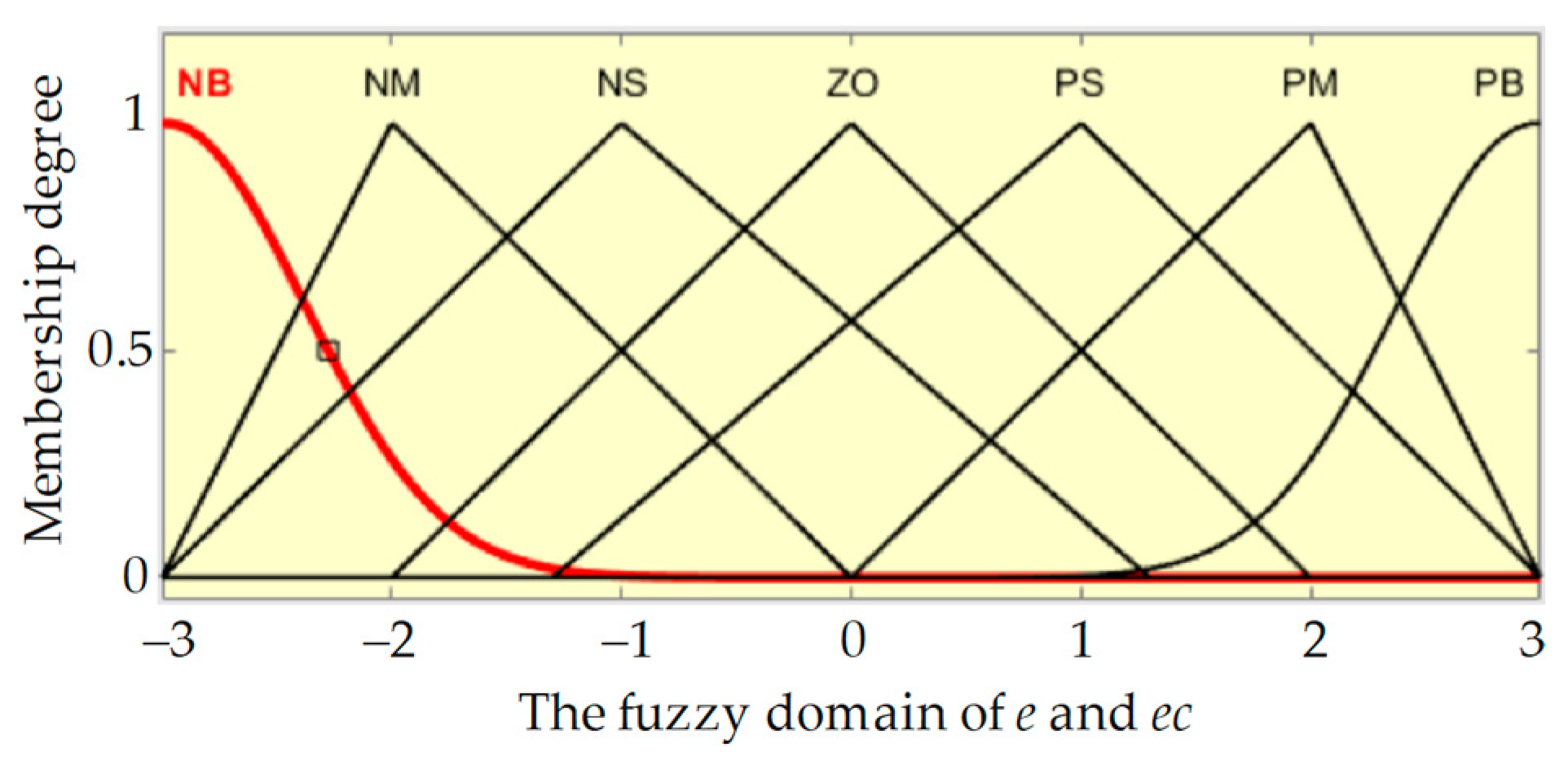
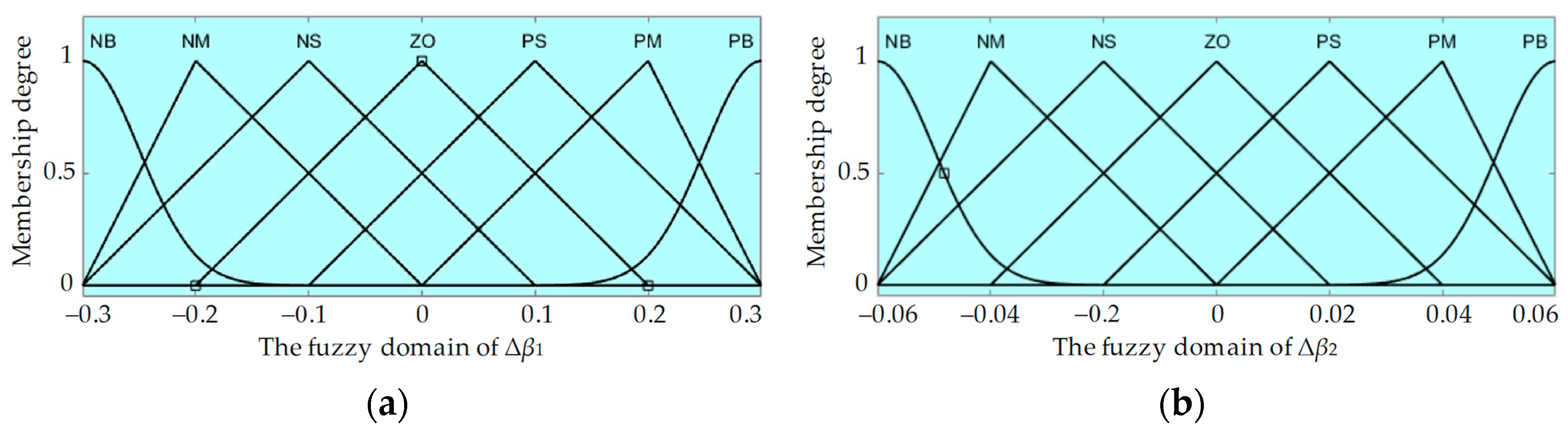
2.3.1. Fuzzy ADRC Controller Design

The fuzzy ADRC controller consists of two parts: fuzzy algorithm and ADRC control.
Han Jingqing [16] proposed an ADRC that includes a tracking differentiator (TD) [17], a nonlinear-state error feedback (NLSEF) [18], and an extended-state observer (ESO) [19]. The core of ADRC technology is to estimate and compensate the total disturbance of the system by reducing the unmodeled dynamic disturbance and the out-of-position disturbance of the system.
TD in ADRC can track the input signal interfered with by noise and extracting its differential signal. The discrete expression of TD is
v 1 ( k + 1 ) = v 1 ( k ) + h v 2 ( k ) v 2 ( k + 1 ) = v 2 ( k ) + h f h ( v 1 ( k ) v 0 ( t ) , v 2 ( k ) , r 0 , h 0 )
where v is the input signal; r0 is the speed factor; h is the integration step; h0 is the filter factor; k is the current moment; fh is the fastest control function of the discrete system.
ESO is the core part of ADRC, which is mainly used to detect the input and output of the system to estimate the interference of the system. For common second-order systems, the ESO discrete expression is
e ( k ) = z 1 ( k ) y ( k ) z 1 ( k + 1 ) = z 1 ( k ) + h [ z 2 ( k ) β 01 e ] z 2 ( k + 1 ) = z 2 ( k ) + h [ z 3 ( k ) β 02 f a l ( e , α 1 , δ ) + b u ] z 3 ( k + 1 ) = z 3 ( k ) + h β 03 f a l ( e , α 2 , δ ) ]
where z1 is the observed value of the system output y; z2 is the observed value of the system output differential; z3 is the observed value of the total disturbance of the system; α1, α2, β01, β02, and β03 are adjustable parameters of the controller; b is the compensation factor of the system; and fal is the noise filter nonlinear function.
NLSEF obtains the actual control quantity of the system through a nonlinear combination of the difference between the estimated value and the actual value observed by ESO. The discrete expression of NLSEF is
e 1 ( k + 1 ) = v 1 ( k + 1 ) z 1 ( k + 1 ) e 2 ( k + 1 ) = v 2 ( k + 1 ) z 2 ( k + 1 ) u 0 ( k + 1 ) = β 1 f a l ( e 1 ( k + 1 ) , α 0 , δ ) + β 2 f a l ( e 2 ( k + 1 ) , α 1 , δ ) u ( k + 1 ) = u 0 ( k + 1 ) z 3 ( k + 1 ) b
where v1 is the tracking signal output from the TD module; v2 is the differentiation of the tracking signal output from the TD module; β1 and β2 are nonlinear error gains and are parameters to be adjusted; u is the final control amount of the system; and u0 is the control amount of the system when it is not compensated. The calculation process of the nonlinear function is the same as that of the ESO part.
From the above, it can be observed that the ADRC controller needs to set more parameters. For instance, the second-order active disturbance rejection controller necessitates the tuning of 14 parameters, with the value range of β01 being [100, 104]. The setting of these parameters significantly increases the difficulty of practically applying the ADRC controller.
Fuzzy control is an intelligent control method that achieves control requirements by simulating human fuzzy reasoning behavior and decision making behavior [20]. The fuzzy control algorithm adaptively adjusts the parameters of NLSEF in ADRC to reduce the time required for parameter setting and enhance the system’s control capability during the design of the active disturbance rejection controller.
The designed fuzzy ADRC controller is illustrated in Figure 3. The equation representing the fuzzy control algorithm for setting the NLSEF parameters is shown as Equation (9). The control process is as follows. The controller compares the theoretical lifting height of the stubble breaking obstacle avoidance device with the actual measured value of the displacement sensor. This comparison yields the error amount e and the error rate ec, which are then converted into fuzzy quantities using the membership function. These fuzzy quantities serve as inputs to the fuzzy controller. The change amounts Δβ1 and Δβ2 corresponding to the gain coefficients β1 and β2 in the NLSEF are also transformed into fuzzy quantities through the membership function, serving as outputs of the fuzzy controller. The controller applies fuzzy inference based on control rules, and ultimately, the output parameters are defuzzified using the center of gravity method to obtain the compensation values of the NLSEF parameters [21].
e 1 ( k + 1 ) = v 1 ( k + 1 ) z 1 ( k + 1 ) e 2 ( k + 1 ) = v 2 ( k + 1 ) z 2 ( k + 1 ) u 0 ( k + 1 ) = ( β 1 + Δ β 1 ) f a l ( e 1 ( k + 1 ) , α 0 , δ ) + ( β 2 + Δ β 2 ) f a l ( e 2 ( k + 1 ) , α 1 , δ ) u ( k + 1 ) = u 0 ( k + 1 ) z 3 ( k + 1 ) b
According to the control process of the fuzzy controller, seven fuzzy linguistic variables are defined as follows: PB (positive large), PM (positive medium), PS (positive small), ZO (zero value), NS (negative small), NM (negative medium), and NB (negative large) [22]. Additionally, based on the experience of parameter regulation of NLSEF in ADRC [23], the theoretical domain of input quantities e and ec is [−3, 3], the theoretical domain of output quantity Δβ1 is [−0.3, 0.3], and the theoretical domain of Δβ2 is [−0.06, 0.06].
The input and output membership functions are formulated by combining Gaussian and triangular functions. Triangular functions are used in the central region, while Gaussian functions are employed on both sides. The choice of a triangular membership function in the middle region simplifies calculations, reduces the number of operations, improves the speed of the controller’s speed, and has less impact on the fuzzy values. On the other hand, the selection of smooth curves and fast convergence Gaussian-type membership functions on the edges of the interval is crucial as they have a greater impact on the system. The membership function curves of the fuzzy controller’s input and output variables are illustrated in Figure 4 and Figure 5.
After establishing the input and output universes and membership functions, fuzzy rules are formulated. The commonly used fuzzy inference methods include the Mamdani method, Zadeh method, Yager method, and Zadeh method. In this paper, the Mamdani method is chosen for fuzzy inference in conjunction with the MATLAB Fuzzy Toolbox. Through repeated debugging and experience summarization, it has been found that the role of Δβ1 is to enhance the system response speed; the larger the value of Δβ1, the faster the system response speed. However, increasing Δβ1 can lead to overshoot and reduce system stability. On the other hand, the role of Δβ2 is to enhance the system dynamic response speed and increase the stability of the system. However, increasing Δβ2 will increase the system regulation time. Based on the variables’ influence on the system, the following fuzzy rules are established:
  • When the deviations of e and ec are large, set Δβ1 as large and Δβ2 as zero or small to increase the system’s response speed and reduce overshoot;
  • When the deviation of e and ec is moderate, set Δβ1 as small and Δβ2 as moderate to ensure a reasonable response time and overshoot range;
  • When e and ec are small, set Δβ1 as large and Δβ2 as large to improve the system’s steady-state performance. The fuzzy rules for Δβ1 are listed in Table 2, and the fuzzy rules for Δβ2 are in Table 3.
The output of fuzzy inference yields a fuzzy value. In practical engineering applications, when the input signal of a control system is an exact value, defuzzification is employed to extract an exact value that best represents the fuzzy set obtained through fuzzy inference. Commonly used defuzzification methods include the regional center of gravity method, weighted average method, maximum criterion method, and maximum membership method. In this study, the regional center of gravity method is selected as the defuzzification method due to its advantages of encompassing all information in the fuzzy subset, providing a smooth inference control output, and achieving a high data utilization rate. The equation for calculating the defuzzified value is as follows:
v 0 = i = 1 m v i μ U ( v ) d v i = 1 m μ U ( v ) d v
where m is the number of fuzzy rules; and U(v) is the output fuzzy set; vi is the value corresponding to the area center of the membership function of the fuzzy subset U, which corresponds to the conclusion of the inference of the ith rule.

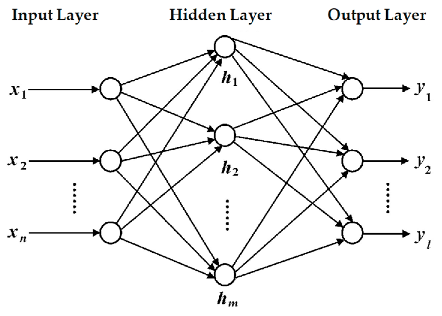
2.3.2. BPNN-Optimized Fuzzy ADRC Controller Design

Although fuzzy control can optimize ADRC parameters to some extent, it has limitations in terms of learning ability and steady-state error. This paper proposes the application of the BPNN algorithm to the fuzzy ADRC controller by inputting the optimized Δβ1 and Δβ2 to the fuzzy ADRC controller to optimize the empirically designed fuzzy controller. This approach not only enhances the system’s nonlinear tracking ability, but also ensures improved system robustness.
In 1985, Rumelhart et al. proposed the BP neural network, which is a multilayer feedforward network utilizing an error backpropagation algorithm. It possesses excellent nonlinear generalization and information processing capabilities. The learning process of the BP neural network primarily involves forward transmission and backpropagation. The standard BP model consists of an input layer, a hidden layer, and an output layer [24]. The network topology is illustrated in Figure 6, with n input nodes, m hidden layer nodes, and one output node.
In this paper, the BPNN algorithm is employed to predict and adjust the β1 and β2 parameters of the fuzzy ADRC. The adjusted parameters Δβ1 and Δβ2 are then input into the NLSEF of the ADRC, enabling parameter sub-regulation of the nonlinear feedback control. The structure diagram of the fuzzy ADRC control based on BPNN is illustrated in Figure 7.
When taking output Δβ1 as an example, the prediction is performed by the BP neural network-optimized fuzzy control. The BP neural network consists of five layers of neurons with a network structure of 2 × 14 × 7 × 7 × 1. The layers include the input layer i, fuzzified layer j, fuzzy rule layer k, output membership layer l, and output layer m. The network utilizes forward propagation and error backward propagation for its operations. The main roles of each layer are as follows:
  • Fuzzified layer: This layer represents the membership function layer, where neurons connected with e and ec are the corresponding seven fuzzy language variables. This layer mainly fuzzifies the two input variables and calculates the membership functions of the fuzzy sets of e and ec belonging to each language variable value, respectively.
  • Fuzzy rule layer: Each neuron in the fuzzy rule layer represents a fuzzy rule and is responsible for calculating the fitness of each rule.
  • Output membership layer: The output membership layer calculates the language variable values of each rule’s output variable.
  • Output layer: The output layer is responsible for defuzzification and obtaining the adjustable parameters of the active disturbance rejection controller. The calculation process of the BPNN optimal fuzzy control is as follows:
    I j = O i , O j = f i j ( x i ) = exp [ O i m i j 2 2 θ i j 2 ] , ( j = 1 , 2 , 49 ) I k = O j , O k = a k = 1 2 i = 1 2 f i j ( x j ) , ( k = 1 , 2 , 49 ) I l = O k , O l = α k m = a k g [ f k m ( z i ) ] , ( m = 1 , l = 1 , 2 , 49 ) , f k m ( z ) = exp [ z i μ k m 2 2 σ i j 2 ] I m = O l , O m = Z m = z α k m z d z z α k m d z = k = 1 49 σ k m μ k m a k k = 1 49 σ k m a k , ( m = 1 )
    where mij is the central value of the membership function of the jth language variable of the ith input variable xi; θij is the width of the membership function of the jth language variable of the ith input variable xi; I is the input of each layer neuron; O is the output of each layer neuron; ukm is the central value of the language-valued membership function of the mth output variable of the first rule; and σ is the width value of the language-valued membership function of the mth output variable of the first rule.

3. Results and Discussion

3.1. Simulation Comparison and Analysis

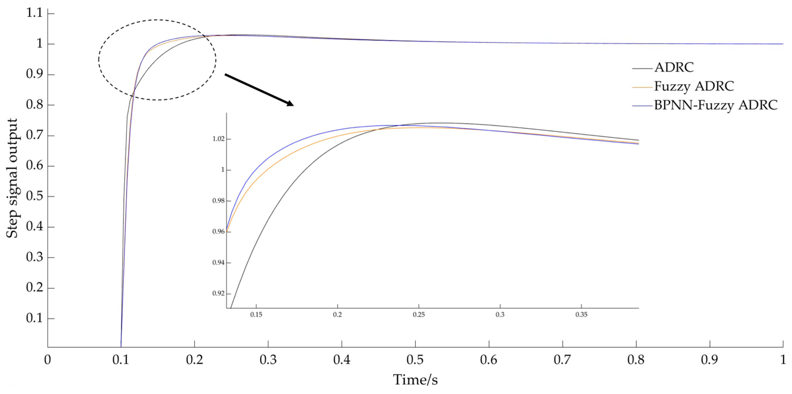
3.1.1. Step Signal Simulation

When avoiding obstacles, the stubble breaking device needs to quickly and stably control the rising and falling positions of the screw slide. Its core is to require the servo motor to work quickly and stably at the target speed, so a step response simulation of the obstacle avoidance control system is performed.
Different controller simulation models of the stubble obstacle avoidance control system are established through the Simulink module in MATLAB software (R2022b). A step signal with an amplitude of 1 is input at time t = 0.1 s, and the response curve is shown in Figure 8. The response characteristics under different control algorithms are shown in Table 4.
According to the ADRC controller simulation test, 14 parameters of the ADRC controller are adjusted. The results are as follows: the integration step size h is 0.01; the filter factor h0 is generally the same as h, which is 0.01; the larger the speed factor r0, the faster the tracking speed. This controller is used for obstacle avoidance control and requires a quick response from the motor, so r0 is set to 1000. The function of β01 and β02 is to suppress vibration. When the system oscillates, the system vibration can be reduced by increasing β01 and β02. β03 mainly affects the hysteresis of system disturbance estimation, that is, the larger its value, the smaller the lag, but excessive expansion of the value of β03 will cause the system to oscillate. Based on experience, β01 is attempted to be made 120, β02 260, and β03 55. The compensation factor of the system is an estimated value, taking 5; a1 takes 0.75; a2 takes 1.25; and δ takes 0.01. β1 functions to improve the system response speed, taking 10; β2 functions to improve the system dynamic response speed, taking 0.001.
From the response curve in Figure 8, we know that the rise time of the fuzzy ADRC and BPNN controller is 0.039 s, both 0.017 s faster than ADRC. The overshoot of the BPNN fuzzy ADRC controller is 0.1%, which is less than 1% of fuzzy ADRC and 2% of ADRC; The adjustment time of the BPNN fuzzy ADRC is 0.089 s, which is smaller than the 0.100 s of the fuzzy ADRC and the 0.303 s of the ADRC. Compared with the fuzzy ADRC and ADRC, the BPNN fuzzy ADRC control system responds more quickly, has a smaller overshoot, and has the shortest time to reach the system steady state. Its significance lies in that when the system detects obstacles, the servo motor can sound quickly, and reach the target value stable state in 0.089 s, the response process is stable, the maximum overshoot is only 0.1%, and there is no steady-state error. The fuzzy ADRC optimized by BPNN has a very significant control effect.

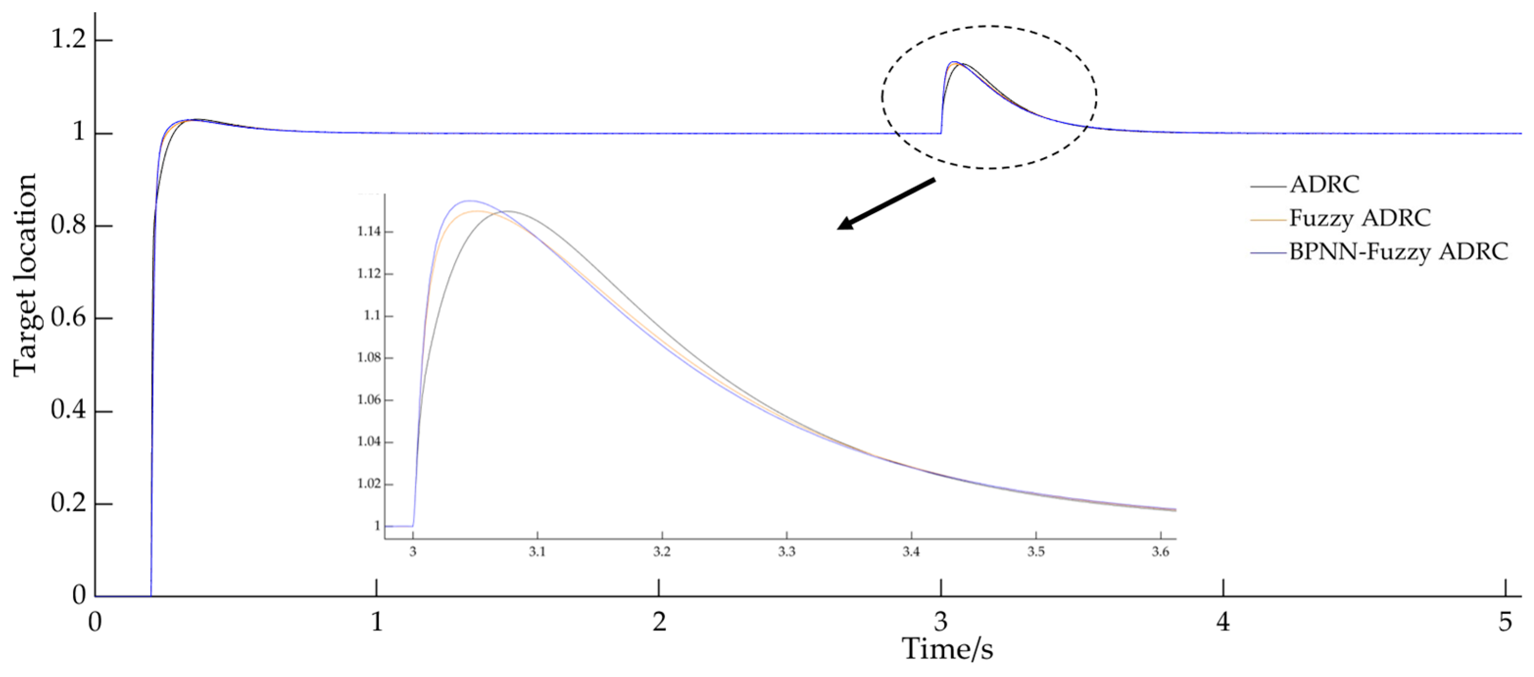
3.1.2. Anti-Disturbance Simulation

When the stubble breaking device is working in the field, the sudden change of ground load will make the servo motor system fluctuate. In order to simulate this working condition, the motor control system is given a noise signal with an amplitude of 1 and a duration of 1 s when simulating 3 s. The response of the system is shown in Figure 9.
It can be seen from Figure 9 that when the servo motor control system receives interference from external signals, the motor response will suddenly change under the three control algorithms. The time for the BPNN fuzzy ADRC to return to the steady state is 0.22 s, which is less than the 0.45 s of the fuzzy ADRC and the 0.56 s of the ADRC. Compared with the fuzzy ADRC and ADRC controller, the fuzzy ADRC optimized using the BPNN algorithm can return to the target value the fastest when subjected to load fluctuations, indicating that the servo motor system is least affected by external interference and improves the stability of the obstacle avoidance control system. Therefore, the use of the BPNN fuzzy ADRC can effectively complete the tracking control of the servo motor to the target signal in the case of load fluctuations.
In summary, the BPNN fuzzy ADRC controller can quickly respond to the tracking control of the target signal and has good dynamic response characteristics. In addition, it can quickly reach the steady-state value when there is load interference, and has stronger anti-interference ability. Its impact in the agricultural environment is that when the no-till planter is operating in stubble breaking and obstacle avoidance, the servo motor can quickly respond to the change in the height position of the obstacle, and under the interference of sudden changes in ground load, it can quickly return to the target value, realizing efficient obstacle avoidance control of obstacles.

3.2. Hardware-in-the-Loop Simulation Platform Experiment

A hardware-in-the-loop simulation, also known as a mathematical–physical simulation, is a method that combines physical and mathematical models with physical objects for testing purposes. This approach combines the intuition and image of physical model-based simulation methods with the speed and convenience of mathematical model-based simulation methods. As a result, it can reduce research costs and shorten the research and development cycle.
While the Simulink module in MATLAB offers powerful computational capabilities and enables the creation of control algorithms for complex systems through various modules, the complex models built in Simulink are primarily intended for simulation test verification purposes. These models are challenging to transfer directly to existing controllers. In many cases, PLCs or industrial controllers serve as the main controllers in existing control systems. However, these controllers often face difficulties in implementing complex algorithms, and their capabilities are typically limited to PID controller algorithms. Therefore, a hardware-in-the-loop simulation platform is established using Simulink (R2022b), PLC (FX3U-16MT), and Kingview software (6.55). This platform allows for the analysis and experimental verification of the control system designed in this paper.

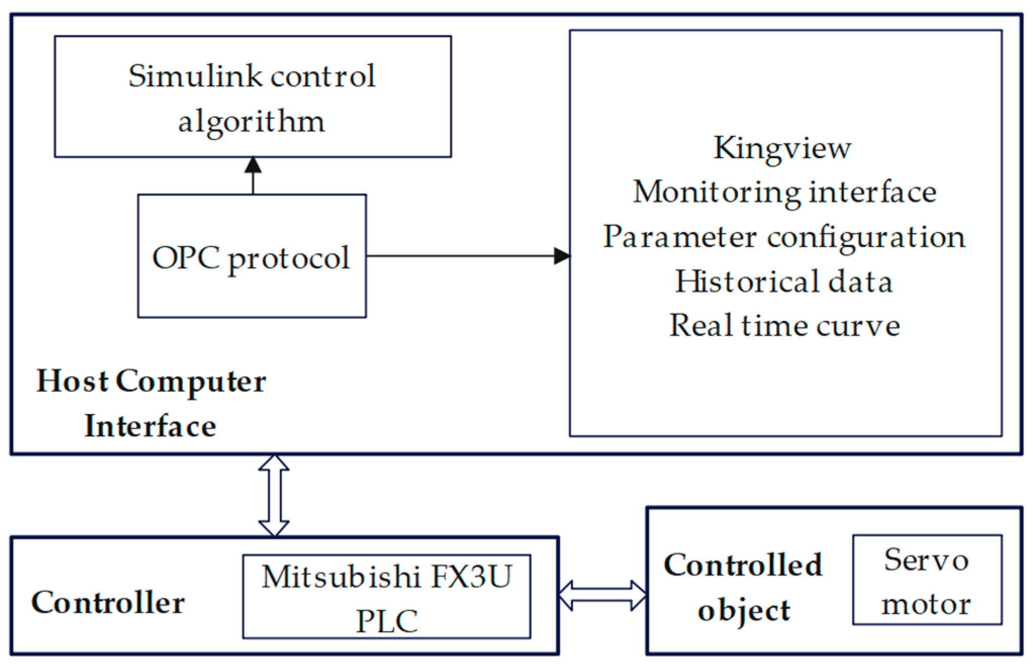
3.2.1. Hardware-in-the-Loop Simulation Platform Building

The hardware-in-the-loop simulation platform adopts the “virtual controller + physical object” configuration, consisting of three main components: the host computer, the controlled object, and the PLC. The overall structure of the platform is depicted in Figure 10. The host computer is a PC equipped with Kingview 6.55 software and MATLAB. Kingview facilitates data communication between MATLAB and the PLC, as well as real-time monitoring of the servo motor speed. MATLAB is utilized for implementing complex algorithms. Since the stubble breaking obstacle avoidance control system primarily involves modifying the speed and steering of the servo motor, the test focuses on the Lichuan servo driver and servo motor chosen for this paper. The main controller employed is the Mitsubishi FX3U-16MT PLC.
OPC communication technology [25] is employed for communication between Simulink and Kingview software, while the R232 serial port facilitates communication between Kingview and the PLC. The configured Simulink model, PLC, Kingview software, sensors, servo drives, servo motors, and power supply are interconnected to establish the hardware-in-the-loop simulation test platform, as illustrated in Figure 11.

3.2.2. Control System Dynamic Performance Experiment

The target height information collected by the ultrasonic sensor, that is, the height of the obstacle, is input into the mathematical model of obstacle avoidance control built in Matlab through the A/D conversion module, and the control instructions are sent to the servo driver by PLC to drive the servo motor. The variation curve of motor speed ω with the target height h is observed. The value of h represents the measured value from the sensor. Figure 12a shows the real-time changing image of the input signal h, while Figure 12b displays the real-time variation curve of the monitored speed ω in Kingview.
From Figure 12, it can be seen that when the input value of h changes, the value of ω adjusts accordingly to reach the target value within 1 s. The experimental results show that the BPNN fuzzy ADRC controller proposed in this paper has strong dynamic response performance for servo motor tracking control.

3.2.3. Control System Error Analysis

From Figure 12a, it can be observed that when the value of h changes continuously in the 2–10 s time period, the value of ω responds quickly to approach the target value. However, overshoot occurs, with the overshoot ranging from 8% to 10%. To investigate the cause of this error, the same signal was simulated in Simulink, and the simulation plot of the speed change was obtained, as shown in Figure 13. Comparing the actual speed image of the servo motor monitored in Kingview with the simulation image, it can be seen that there is no overshoot in the simulation image. Hence, it can be concluded that the cause of the overshoot is not related to the BPNN-based fuzzy control algorithm designed in this paper. Furthermore, when the servo motor’s actual speed was monitored by Kingview outside the 2–10 s time period and compared with the given theoretical values, it can be observed from the ten sets of experimental data listed in Table 5 that the maximum error is 1.9 r/min.
A test was conducted on the PLC and servo motor using Kingview to send ten different sets of speed commands to the servo motor. The actual speed values of the servo motor corresponding to each speed command were recorded on the servo motor display. The test data obtained are listed in Table 6.
From Table 5, it can be seen that the maximum error is 4 r/min, and the average error is 1.4 r/min in the ten sets of tests. This is consistent with the difference between the actual speed and the theoretical speed of the servo motor in the time period other than 2–10 s. Therefore, it can be concluded that the overshoot observed during the time period of 2 to 10 s, when the speed changes continuously and rapidly, is due to the communication delay between MATLAB and Kingview, which is inherent to the system itself.
The results show that the control system error of the BPNN fuzzy ADRC controller designed in this paper is within a certain reasonable range and can meet the requirements of obstacle avoidance control of stubble breaking device in the agricultural field.
In summary, through the hardware-in-the-loop simulation platform built, the physical control of the servo motor of the controlled object is realized by the BPNN fuzzy ADRC controller designed in this paper. The experimental results show that the BPNN fuzzy ADRC controller has better control performance, which verifies the rationality of the BPNN controller designed in this paper.

4. Conclusions

Due to the presence of a large number of rocks and exposed bedrock in the fields of the rocky desertification area of southwest China, the application of no-tillage seeders for stubble breaking operations is restricted. Solving the problem of autonomous obstacle avoidance control of the stubble breaking device is of great significance for improving the service life of the machine and efficient production.
In order to improve the obstacle avoidance control performance and anti-interference ability of a stubble breaking device of a no-tillage planter, a BPNN fuzzy ADRC controller is designed to optimize the control performance of a servo motor. Establishing a mathematical model for obstacle avoidance control of the stubble breaking device, and simulation analysis and hardware-in-the-loop simulation experiment are conducted for servo motor control performance optimization using the ADRC, fuzzy ADRC, and BPNN fuzzy ADRC controller. The following main conclusions are obtained:
  • Through the analysis of the implementation of conservation tillage technology in the rocky desertification areas of southwest China, an autonomous obstacle avoidance control system for stubble breaking devices was designed, and a model of the stubble breaking and obstacle avoidance control system was built. The method of obstacle avoidance control using the BPNN-algorithm-optimized fuzzy ADRC was proposed. Moreover, the experiments show that optimizing the NLSEF parameters of the fuzzy ADRC controller using the BPNN algorithm with strong learning ability can improve the system’s control performance and anti-inference capability while avoiding overly relying on expert experience in fuzzy control.
  • According to the performance indexes of the simulation results, it can be seen that the fuzzy ADRC obstacle avoidance control system based on BPNN optimization reduces the regulation time by 70.6% and 1.1%, and the overshoot is reduced by 95% and 90%, respectively. Moreover, the system can return to a steady state as soon as possible after introducing noise signal interference, proving that the model has high dynamic stability and anti-interference capability.
  • A hardware-in-the-loop simulation experiment platform of the obstacle avoidance control system was built, and the results demonstrated that the BPNN fuzzy ADRC controller has a regulation time of less than 1 s for each servo motor response speed change when the input signal is a continuous step signal. When the target position h changes rapidly and continuously in the 2–10 s, at this time, although the speed ω can quickly approach the target value, there will be an overshoot, and the overshoot is 8–10%, which is different from the simulation results. After theoretical analysis, it is concluded that the source of error is an unavoidable system error. Therefore, the control system proposed still has an excellent control effect within the error range. The hardware-in-the-loop platform experiment could verify the reasonableness and feasibility of the BPNN fuzzy ADRC controller designed in this paper.
The designed BPNN fuzzy ADRC controller improves the stability and interference immunity of servo motor control and has practical significance for solving real-time autonomous obstacle avoidance during stubble breaking operations of no-tillage seeders in rocky desertification areas of southwest China. The service life of the stubble breaking device and agricultural production efficiency are improved. This research can provide reference for the design and improvement of the autonomous obstacle avoidance control system of the stubble breaking device when operating no-tillage seeders in rocky desertification areas of southwest China. The serious rocky desertification of the soil in southwest China has made it more difficult for the practical application of no-till seeders in stubble breaking operations. It is also necessary to strengthen the research on machine vision detection algorithms for field gravels and stones to improve the obstacle recognition rate, thereby improving the stubble breaking operations and device obstacle avoidance performance.

Author Contributions

Conceptualization, H.Z.; Data curation, H.Z. and T.H.; Formal analysis, T.H.; Funding acquisition, H.Z.; Investigation, T.H.; Project administration, L.B.; Resources, L.B.; Software, W.Z.; Supervision, L.B.; Validation, W.Z.; Writing—original draft, T.H. and W.Z.; Writing—review and editing, T.H. and L.B. All authors have read and agreed to the published version of the manuscript.

Funding

This research was funded by the National Natural Science Foundation of China, grant numbers 51865022 and 52265033.

Institutional Review Board Statement

Not applicable.

Data Availability Statement

The analyzed datasets are available from the corresponding author on reasonable request.

Conflicts of Interest

The authors declare no conflicts of interest.

References

  1. Pan, D.H.; Jia, H.C.; Chen, F.; He, Y.H.Z. Impacts of rocky desertification on maize drought risk in Southwest China. Trans. Chin. Soc. Agric. Eng. 2017, 33, 172–178. [Google Scholar]
  2. National Bureau of Statistics of China. China Statistical Yearbook; China Statistics Press: Beijing, China, 2023.
  3. Song, L.H.; Wang, K.H.; Yan, X.M. Characteristics of soil fauna communities in the Karst region, Southwest China, based on meta-analysis. Acta Ecol. Sin. 2018, 38, 984–990. [Google Scholar]
  4. Liu, X.; Wang, R.T.; Zhang, F. Research on evaluation of food security in southwest China. J. Southwest Univ. (Nat. Sci. Ed.) 2024, 46, 115–124. [Google Scholar]
  5. He, J.; Li, H.W.; Chen, H.T.; Lu, C.Y.; Wang, Q.J. Research progress of conservation tillage technology and machine. Trans. Chin. Soc. Agric. Mach. 2018, 49, 1–19. [Google Scholar]
  6. Wang, Q.J.; Cao, X.P.; Wang, C.; Li, H.W.; He, J.; Lu, C.Y. Research progress of no/minimum tillage corn seeding technology and machine in northeast black land of China. Trans. Chin. Soc. Agric. Mach. 2021, 52, 1–15. [Google Scholar]
  7. Han, J.Q. Auto- disturbances- rejection controller and it’s applications. Control Decis. 1998, 13, 19–23. [Google Scholar]
  8. Tian, H.T.; Xie, Y.; Shi, L.L.; Liu, H. Application of fuzzy cuckoo search algorithm in active disturbance rejection control of variable pitch of wind turbines. Acta Energiae Solaris Sin. 2021, 42, 222–229. [Google Scholar]
  9. Wang, S.M.; Fan, W.C. Simulation application of improved second order ADRC in PMSM. Fire Control Command Control 2020, 45, 162–166. [Google Scholar]
  10. Li, J.Z.; Xu, P.F.; Zhou, H.P.; Zheng, C.L. Research on traction motor control strategy of mine electric locomotive based on improved ADRC. Coal Technol. 2022, 41, 177–181. [Google Scholar]
  11. Qu, L.Z.; Qiao, W.; Qu, L.Y. Active-disturbance-rejection-based sliding-mode current control for permanent-magnet syn-chronous motors. IEEE Trans. Power Electron. 2021, 36, 754. [Google Scholar] [CrossRef]
  12. Tian, B.; Cui, J.; Lu, H. Adaptive finite-time attitude tracking of quadrotors with experiments and comparsons. IEEE Trans. Ind. Electron. 2019, 66, 9428–9438. [Google Scholar] [CrossRef]
  13. Li, F.P. Study on ADRC parameter optimization using CPSO for clamping force control system. Math. Probl. Eng. 2018, 2018, 2159274. [Google Scholar] [CrossRef]
  14. Yang, Y.; Sun, Q.; Zhu, Q.X.; Chen, S. Dynamic performance optimization of machine tool ballscrew feed system based on comprehensive indicators. Trans. Chin. Soc. Agric. Mach. 2019, 50, 404–412. [Google Scholar]
  15. Jeong, H.S. Novel torque motor model for performance design and analysis of a servo valve with permanent magnets. J. Mech. Sci. Technol. 2018, 32, 2253–2259. [Google Scholar] [CrossRef]
  16. Han, J.Q. From PID technique to active disturbances rejection control technique. Control Eng. China 2002, 9, 13–18. [Google Scholar]
  17. Han, J.Q.; Wang, W. Nonlinear tracking-differentiator. J. Syst. Sci. Math. Sci. 1994, 14, 177–183. [Google Scholar]
  18. Han, J.Q. Nonlinear state error feedback control law-NLSEF. Control Decis. 1995, 10, 221–225. [Google Scholar]
  19. Han, J.Q. The “extended state observer” of a class of uncertain systems. Control Decis. 1995, 10, 85–88. [Google Scholar]
  20. Boukhalfa, G.; Belkacem, S.; Chikhi, A. Genetic algorithm and particle swarm optimization tuned fuzzy PID controller on direct torque control of dual star induction motor. J. Cent. South Univ. 2019, 26, 1886–1896. [Google Scholar] [CrossRef]
  21. Tian, M.; Bai, J.B.; Li, J.Q. Variable rate fertilization control system for liquid fertilizer based on genetic algorithm. Trans. Chin. Soc. Agric. Eng. 2021, 37, 21–30. [Google Scholar]
  22. Zhang, K.F.; Jiang, T.; Shao, L.; Su, L.C.; Ye, T. Research on precision temperature control of laser diode based on the novel fuzzy-PID conrol unit. Opt. Precis. Eng. 2017, 25, 648–655. [Google Scholar] [CrossRef]
  23. Zhang, C.Y.; Dong, W.J.; Xiong, Z.Q.; Hu, Z.Q.; Wang, D.H.; Ding, Y.C. Design and experiment of fuzzy adaptive pure pursuit control of crawler-type rape seeder. Trans. Chin. Soc. Agric. Mach. 2021, 52, 105–114. [Google Scholar]
  24. Zhang, D.S.; Yang, G.; Zhao, X.T.; Yang, X.Q.; Gao, X.F. Optimization design of vane diffuser and volute in vertical centrifugal pump based on back propagation neural network. Trans. Chin. Soc. Agric. Mach. 2022, 53, 130–139. [Google Scholar]
  25. Qing, Y.; Liu, Z.Y.; Zhang, Y. Research and Practice of Neural Network PID Process Control Algorithm Based on Offshore Oil and Gas Platform. J. Phys. Conf. Ser. 2020, 1486, 032039. [Google Scholar]
Figure 1. The overall structure. Note: 1. profile wheel; 2. machine frame; 3. guide wheel; 4. stubble breaker; 5. lifting connecting rod; 6. ultrasonic sensor; 7. servo motor; 8. synchronous belt; 9. screw slide table module; 10. PLC; 11. servo driver.
Agriculture 14 00786 g001
Figure 2. Block diagram of the stubble breaking and obstacle avoidance control system.
Agriculture 14 00786 g002
Figure 3. Fuzzy active disturbance rejection control structure block.
Agriculture 14 00786 g003
Figure 4. Input variable membership function graph.
Agriculture 14 00786 g004
Figure 5. Output variable membership function graph. (a) Membership function graph of Δβ1; (b) membership function graph of Δβ2.
Agriculture 14 00786 g005
Figure 6. BP network topology.
Agriculture 14 00786 g006
Figure 7. Schematic diagram of the BPNN-optimized fuzzy ADRC.
Agriculture 14 00786 g007
Figure 8. Step response comparison.
Agriculture 14 00786 g008
Figure 9. Disturbance response comparison of different controllers.
Agriculture 14 00786 g009
Figure 10. Overall structure of the hardware-in-the-loop simulation experiment platform.
Agriculture 14 00786 g010
Figure 11. Physical structure of the hardware-in-the-loop simulation experiment platform.
Agriculture 14 00786 g011
Figure 12. Kingview real-time monitoring screen. (a) Real-time changing image; (b) ω changes images in real time with h.
Agriculture 14 00786 g012
Figure 13. Speed change diagram obtained by the Simulink simulation.
Agriculture 14 00786 g013
Table 1. Lift control system parameters.
ParameterSymbolValueUnit
LoadG80kg
Screw diameterd10cm
Lifting effective strokex200mm
Lifting speedV0.1m/s
Screw leadPAo10mm/r
Motor powerP400w
Motor rated speedω3000rpm
Motor rated torqueT1.28N·m
Rotor moment of inertiaJ0.008kg·m2
Torque coefficientKt1.27N·m
Armature inductanceL0.002H
Stator resistanceR2Ω
Back EMF coefficientKe0.008V/rpm
Number of pole pairsPn4
Table 2. Fuzzy control rule table of Δβ1.
ecNBNMNSZOPSPMPB
e
NBPBPBPMPMPSZOZO
NMPBPBPMPSPSZONS
NSPMPMPMPSZONSNS
ZOPMPMPSZONSNMNM
PSPSPSZONSNSNMNM
PMPSZONSNMNMNMNB
PBZOZONMNMNMNBNB
Table 3. Fuzzy control rule table of Δβ2.
ecNBNMNSZOPSPMPB
e
NBPSNSNBNBNBNMPS
NMPSNSNBNMNMNSZO
NSZONSNMNMNSNSZO
ZOZONSNSNSNSNSZO
PSZOZOZOZOZOZOZO
PMPBPSPSPSPSPSPB
PBPBPMPMPMPMPSPB
Table 4. Response results of different control algorithms.
TypeRise Time/sOvershoot/%Adjustment Time/s
ADRC0.05620.303
Fuzzy ADRC0.03910.100
BPNN Fuzzy ADRC0.0390.10.089
Table 5. Experiment data 1.
Test NumberKingview Input Command (r/min)Servo Motor Speed (r/min)
100
26060
3120121
4300302
5500499
6800795
712001198
815001504
920001997
1025002501
Table 6. Experiment data 2.
Test NumberKingview Input Command (r/min)Servo Motor Speed (r/min)
100
28081
3100102
4300299
5500496
6800800
712001198
818001800
920002001
1028002797
Disclaimer/Publisher’s Note: The statements, opinions and data contained in all publications are solely those of the individual author(s) and contributor(s) and not of MDPI and/or the editor(s). MDPI and/or the editor(s) disclaim responsibility for any injury to people or property resulting from any ideas, methods, instructions or products referred to in the content.

