Article

The Mechanical Analysis and Comparative Performance Test of the Roller-Type Pulling Mechanism for the Whole Cotton Stalk Pulling Machine

1
College of Electromechanical Engineering, Xinjiang Agricultural University, Xinjiang Uygur Autonomous Region, Urumqi 830052, China
2
Nanjing Institute of Agricultural Mechanization, Ministry of Agriculture and Rural Affairs, Nanjing 210014, China
*
Author to whom correspondence should be addressed.
Agriculture 2024, 14(3), 506; https://doi.org/10.3390/agriculture14030506
Submission received: 6 February 2024 / Revised: 12 March 2024 / Accepted: 16 March 2024 / Published: 21 March 2024
(This article belongs to the Section Agricultural Technology)

Abstract

:
In order to address the common difficulties in pulling and harvesting whole cotton stalks, such as high pulling resistance, high miss-pulling rate, and high breakage rate, which severely hinder the recycling of cotton stalks, three different pulling mechanisms with different pulling principles (wrapping-type pulling mechanism, clamping-type pulling mechanism, transverse roller-type pulling mechanism) were designed. The pulling force on cotton stalks during the pulling process of the three different roller-type pulling mechanisms was compared and analyzed, clarifying the mechanism of roller-type whole cotton stalk pulling mechanisms and identifying situations with optimal pulling force. Field comparative experiments were conducted to compare the working performance of different roller-type pulling mechanisms in the field, and a comprehensive analysis of two key indicators in pulling cotton stalks, miss-pulling rate and breakage rate, was carried out. The results showed that the pulling method and pulling force of the pulling mechanism played a crucial role in the successful pulling of cotton straws. Comparative analysis of the three pulling mechanisms revealed that the clamping-type pulling mechanism had the highest pulling force. The standard deviation means of the missed pull rates for mechanisms X1, X2, and X3 were 0.83%, 0.59%, and 0.43%, respectively, while the standard deviation means of the breakage rates were 1.48%, 1.79%, and 0.49%, respectively. The enveloping-type pulling mechanism had a higher missed pull rate with an average of 8.32%, and the clamping-type pulling mechanism resulted in excessive breakage of cotton straw during operation, with an average breakage rate of 14.10%. In contrast, the transverse roller-type straw pulling mechanism performed the best in the field performance test, as it did not require precise alignment and had an average missed pull rate of 4.55% and an average breakage rate of only 7.55%. Considering the practical needs of agriculture production, the transverse roller-type straw pulling mechanism is recommended as the pulling device for cotton straw harvesting. The research results can provide a reference for the design selection of whole-plant straw pulling mechanisms.

1. Introduction

Whole-stalk cotton straw harvesting, as a practical technology to enhance agricultural sustainability, aims to effectively utilize the additional value of cotton straw. It can be used for composting, manufacturing mixed feed, compressed boards, and microwave carbon cracking, thereby comprehensively utilizing renewable agricultural biomass resources. China is the world’s largest producer of cotton [1,2] with a unique advantage in cotton resources. The majority of cotton planting in China adopts the mulch-drip irrigation planting mode. After the cotton is harvested using the cotton picker [3,4], joint operation machines are commonly used for cotton straw crushing and residual film recovery. However, there are challenges in the decomposition of cotton straw stubble and roots left in the field after straw crushing [5,6,7,8], as well as the difficulty of separating cotton straw from the residual film due to the cutting of straw using the straw crusher [9,10]. This mixture of cotton straw and residual film makes it difficult to carry out residual film recovery work effectively.
The roller-type cotton straw harvesting mechanism is the main equipment currently used for whole-stalk cotton straw harvesting. Whole-stalk cotton straw harvesting not only generates certain economic benefits but also helps maintain the integrity of the plastic film after harvesting [11,12,13,14,15,16,17], which is beneficial for the operation of the residual film recovery machine. Currently [2,18], researchers (China, United States, India, Sudan, Egypt) have conducted in-depth research on the performance of cotton straw harvesting mechanisms from the aspects of machine structure parameters and operating objects. They have developed various types of mechanisms for whole-stalk cotton straw harvesting. However, existing models often experience the breaking or missing of cotton straw during operation [19,20,21,22], which limits the widespread adoption of whole-stalk cotton straw harvesting. Therefore, it is necessary to comparatively analyze the relationship between the influence of the force on the cotton stalks and the pulling performance indexes under different methods of cotton stalk pulling.
In order to improve the efficient utilization, intensification, and circular use of cotton straw resources, reduce the impact of residual root stubble on residual film recovery, and promote the further development of the cotton industry towards precision farming [23], it is necessary to develop a cotton straw harvesting mechanism that does not damage the plastic film, leave root stubble, and achieve high rates of clean straw extraction while minimizing straw leakage. Based on the mechanical analysis of different roller-type cotton straw harvesting mechanisms [24], it is necessary to conduct field comparative experiments to find the most effective mechanism for whole-stalk cotton straw harvesting. This research aims to provide valuable insights for the design and improvement of cotton straw harvesting mechanisms, thereby fundamentally solving the challenges associated with whole-stalk cotton straw harvesting.

2. Materials and Methods

2.1. Working Principle of the Pinch Roller Extraction Mechanism

2.1.1. Basic Working Principle

As shown in Figure 1, the pinch roller-type of cotton stalk pulling mechanisms is mainly divided into four motion stages, including the initial contact between the pulling part and the cotton stalks, the clamping stage, the pulling stage, and the throwing stage.
Cotton stalks are subjected to the clamping force Fn and Fn’ of the pinch rollers, the gravity of the cotton stalks themselves G, the tensile force of the cotton stalks and the soil resistance Fs when pulling, the machine forward on the cotton stalks produced by the forward thrust Fm, the pinch rollers through the clamping of the cotton stalks and the static friction required for the pulling of the cotton stalks f. When the soil resistance is greater than the pulling force, the cotton stalks can not be pulled out; when the soil resistance Fs is less than the pulling force from the initial contact with the cotton stalks by the pulling parts of the clamping force and the machine forward, with the combined force of the thrust, it was pulled out of the soil surface; when the soil resistance Fs is greater than the cotton stalks and the tensile force is greater than the friction f, the phenomenon of leakage of pulling occurs; when the soil resistance Fs is greater than the friction f, which is then greater than the tensile force of the cotton stalks, the phenomenon of pulling off occurs.

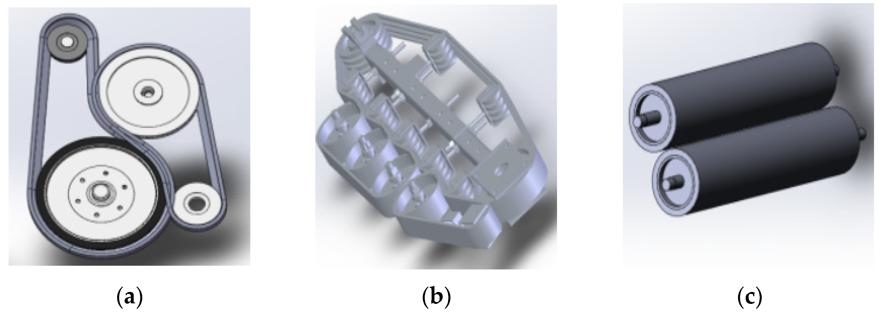
2.1.2. Types of Pinch Roller Extraction Mechanisms

At present, in the domestic design and development of more types of cotton stalk pulling mechanisms, the more commonly used is the wrapping-type pulling mechanism, followed by the clamping-type pulling mechanism and cross roller-type pulling mechanism. For this reason, the above three kinds of cotton stalk pulling mechanism are selected for research and analysis. As shown in Figure 2, the three kinds of pulling mechanism are Figure 2a for the wrapping type (commonly used), Figure 2b for the clamping type (commonly used), and Figure 2c for the cross roller type (a new design, that does not need two rows of the pulling and harvesting mechanism). The three kinds of pulling components work at the height of the pulling point, which is 40 to 60 mm, according to the structure of the different pulling mechanisms that have been selected.

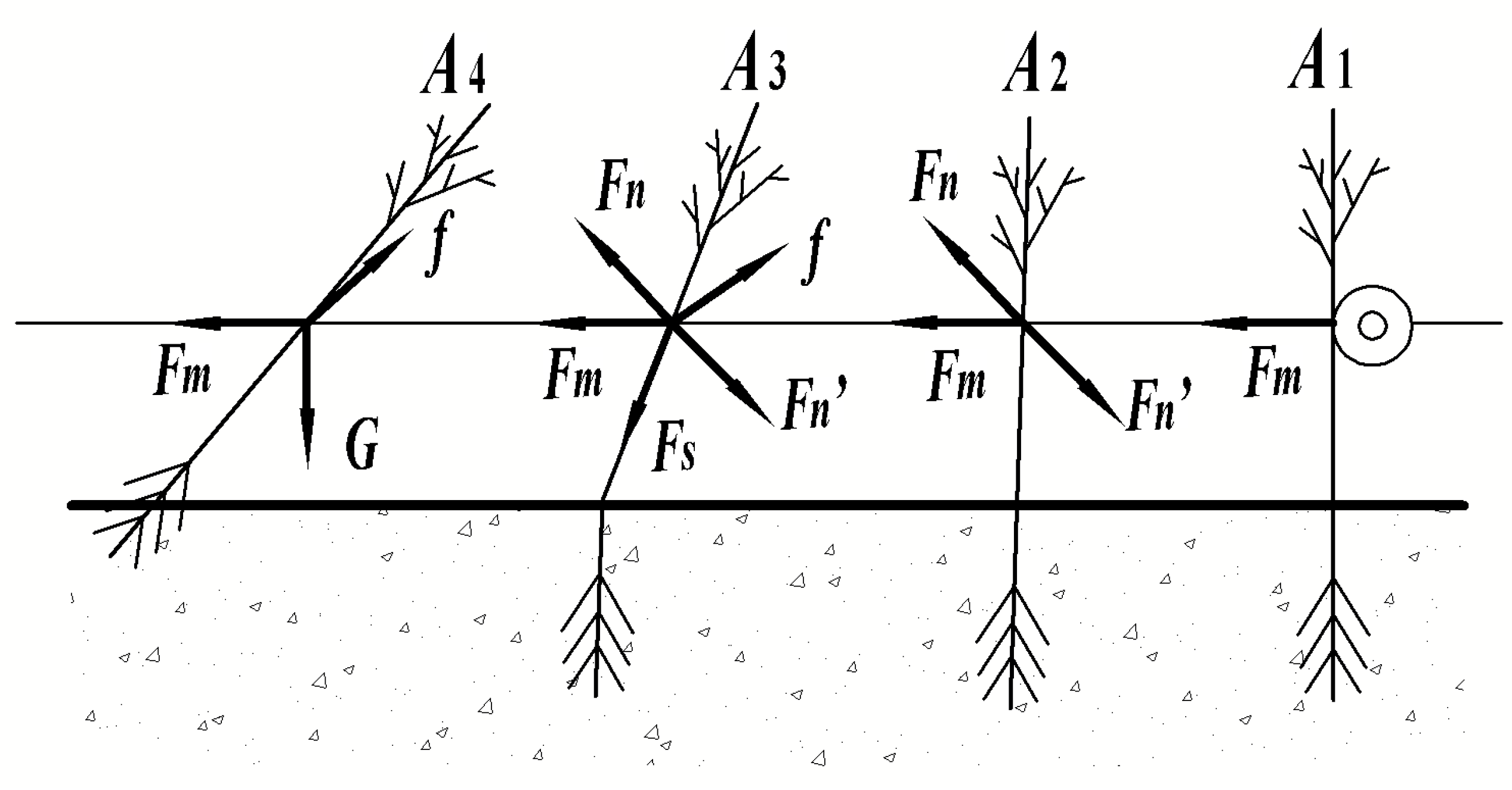
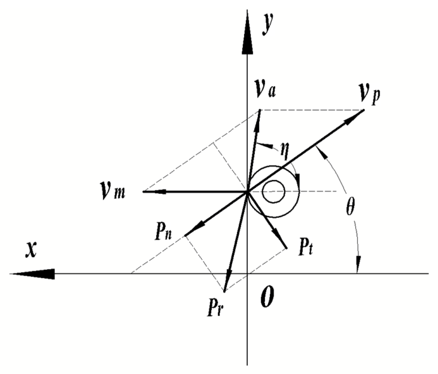
2.2. Mechanical Analysis of Nip-Roller-Type Cotton Stalk Whole Plant Plucking Mechanism

The basic working parameters of the pinch roller plucking mechanism include the plucking angle θ (the angle of inclination of the plucking mechanism and the horizontal plane), the linear velocity of the plucking mechanism of the pinch roller vp. These factors ensure that the plucking process of the plucking force and the direction of the vertical axis of the cotton stalks is the same, to prevent the cotton stalks from being subjected to too large a radial force in the process of the whole plucking and breaking, thus reducing the rate of plucking breakage of the cotton stalks. In the work process of the pinch roller plucking mechanism, the cotton stalks are affected by the horizontal forward speed direction of the plucking mechanism and the plucking mechanism plucking linear speed direction; the combined speed between the two is the direction of the speed of the cotton stalks plucking process. In order to make the direction of the plucking speed of the cotton stalks tilted upward, it is necessary to adjust the plucking mechanism plucking direction and the direction of the mechanism forward to the direction reversal of the oblique backward movement, as shown in Figure 3.
Concerning the cotton straw plucking rubber belt, the plucking resistance is Pr, where the Pr force is separated into Pt and Pn forces; Pt for the rubber belt friction overheating failure slippery force, Pn in the plucking conditions to make the rubber belt fracture force. Their relationship is as follows:
P t = P r cos θ P n = P r sin θ ,
Pulling up both sides of the pressure to the rubber belt, in the rubber belt, positive pressure distribution is not uniform; the closer to the pinch roller side, the larger the pinch roller mechanism to ensure that there is enough friction to tighten the cotton stalks. This also acts to eliminate a part of the harmful resistance and to prevent the edge of the rubber belt to open up resulting in the leakage of the cotton stalk’s pulling.
The absolute velocity va of the cotton stalks entering into the pinch roller gap can be determined according to the following formula:
δ = v p v m v a = v m 2 + v p 2 2 v p v m cos θ v a = v m 1 + δ 2 2 δ cos θ ,
The direction of the absolute velocity va can be determined from the velocity triangle, then:
v a v m = sin θ sin ( η θ ) = 1 + δ 2 2 δ cos θ ,
The direction of the absolute velocity va is determined by the angle η, which is obtained by coupling Equations (2) and (3):
η = arcsin sin θ 1 + δ 2 2 δ cos θ + θ ,
The η angle is related to the θ angle and the speed ratio of vm and va. From Equation (4), when the θ angle is a constant, the smaller the δ value, the larger the η angle, and the greater the degree of forward tilt of the cotton stalks.
If η = π/2, then
v m = v p cos θ ,
From the perspective of the pulling force required for uprooting, it is advantageous for the mechanism to uproot the cotton stalk in this way. Equation (5) does not consider the slipping effect generated when the mechanism fractures the cotton stalk structure during the clamping moment.
The following mechanism analysis is carried out for each of the three types of cotton straw whole-plant uprooting mechanism in the uprooting stage; the cotton straw root force is about to be out of the soil anchoring effect of the moment of the ideal state.

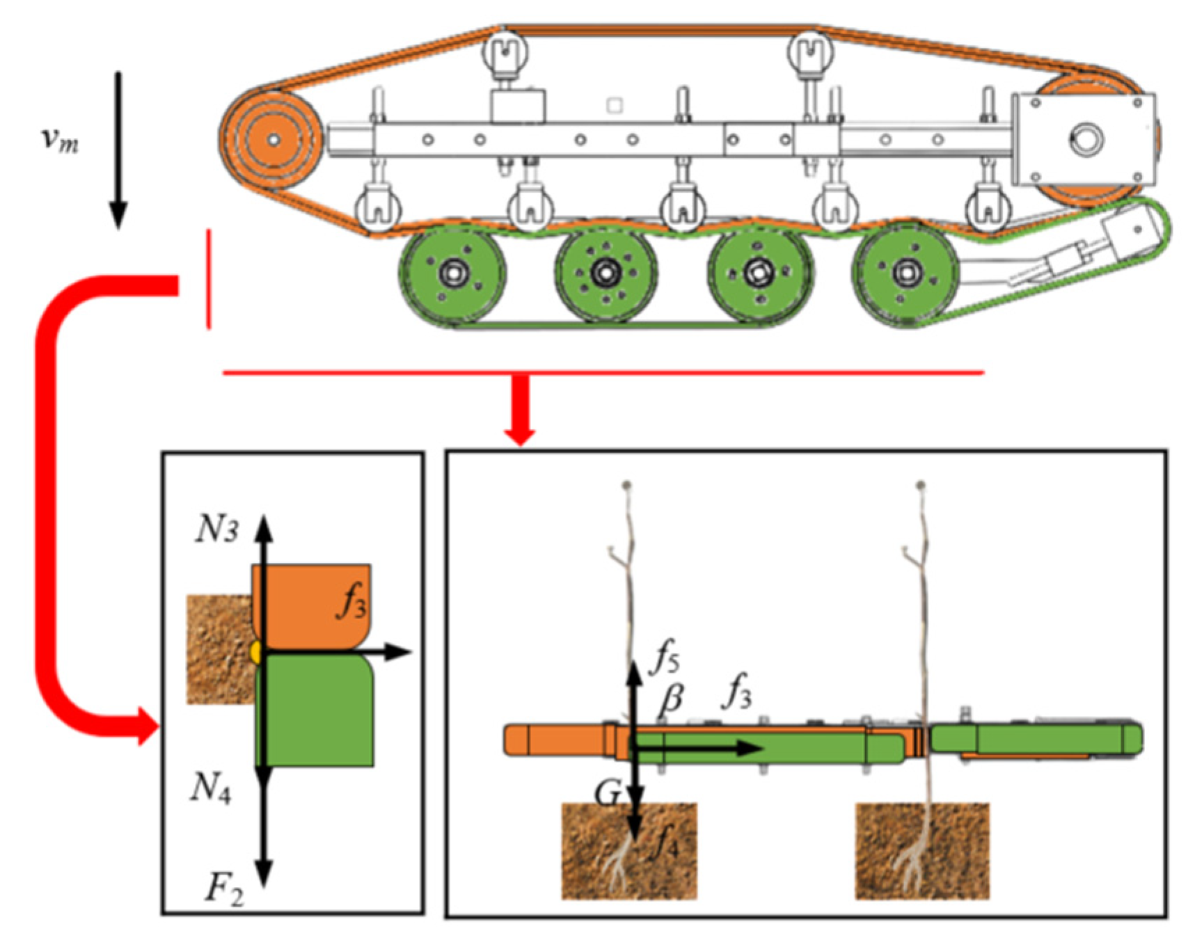
2.3. Analysis of Lifting Mechanism of Wrapping-Type Lifting Mechanism

The wrapping-type lifting mechanism is more commonly used in the area of cotton field agricultural machinery plucking mechanisms, mainly used for whole plant plucking and harvesting. As a whole-plant plucking mechanism, the two sides of the belt pinch rollers use a staggered cross-arrangement. The flexible rubber pinch roller has a curved path of whole-plant plucking, and the structure of it is relatively simple, very reliable, and its manufacturing costs are relatively low.
However, the initial contact of the agency is more difficult to align; the cotton stalks need to pass through the extra grain splitter cluster in order to be accurately sent to the tractor under the traction of the flexible rubber clamping roller gap, and ultimately by the relative movement of the flexible rubber clamping roller pulling the root out of the soil, as the whole cotton stalks are pulled up and then thrown to the side of the agency upon the ground’s surface.
The wrapping-type lifting mechanism’s movement for the composite movement works through the forward movement of the machine and the lifting mechanism of the rotation of the composition. The forward movement of the machine provides forward thrust F1 (N), and pinch rollers rotate in the opposite direction to produce friction f2 (N). Figure 4 shows the force analysis of the wrapped lifting mechanism.
The sufficient conditions for the whole cotton stalk to be lifted out of the soil anchorage using the pinch roller mechanism are:
f 2 c o s α > F 1 f 2 s i n α > f 1 f 2 cos a F 1 = m a 1 x f 2 sin a ( f 1 + G 1 ) = m a 1 y μ ( N 1 + N 2 ) = f 2 ,
where α is the wrap-around mechanism and ground inclination (°), μ is the coefficient of friction between belt and straw, α1 is the acceleration in the forward direction of the wraparound mechanism (m/s2), F1 is the thrust on the cotton stalks by the forward movement of the wrapping mechanism (N), N1 is the extrusion force of active rollers on cotton stalks (N), N2 is the squeezing force of the follower rollers on the stalks (N), f2 is the friction of double belts on cotton stalks (N), f1 is the soil resistance during lifting (N), and G1 is the cotton Straw Gravity (N).
The wrapping-type lifting mechanism operation, where the cotton stalks can be pulled up smoothly using the pinch roller rubber and the friction generated by the clamping of the cotton stalks to determine the equilibrium equation, is
f 2 = 0 J 2 π ρ z K 1 h d h ,
From Equations (6) and (7), the equations for the acceleration a1x (m/s2) in the forward direction of the mechanism and the acceleration a1y (m/s2) in the vertical direction at the instant of cotton stalk uplift can be derived as
a 1 x = μ ( N 1 + N 2 ) cos a F 1 m a 1 y = μ ( N 1 + N 2 ) sin a 0 J 2 π ρ z K 1 h d h G 1 m ,
where ρ is the maximum static friction factor between soil and roots of cotton stalks, Z is the heavy soil (°), K1 is the lateral earth pressure coefficient, h is the height of culm clamping area from the ground (mm), J is the cotton stalk length (mm), a1x is the acceleration of cotton stalks in the horizontal direction at the time of upliftment (m/s2), and a1y is the acceleration in the vertical direction at the time of straw pull-up (m/s2).
The greater the acceleration of cotton stalks plucking, the greater the plucking force of the wrapping-type lifting mechanism. The greater the speed of the wrapped plucking mechanism, the faster the forward speed; in the case of a certain distance between the cotton stalks, the cotton stalks are fed into the pinch roller gap in a shorter time. When the acceleration in the horizontal direction of the cotton stalks pulling up is more than the vertical direction of the cotton stalks pulling up’s acceleration, it makes part of the cotton stalks feeding untimely, resulting in the stalks being unable to enter the pinch roller gap without leakage pulling.

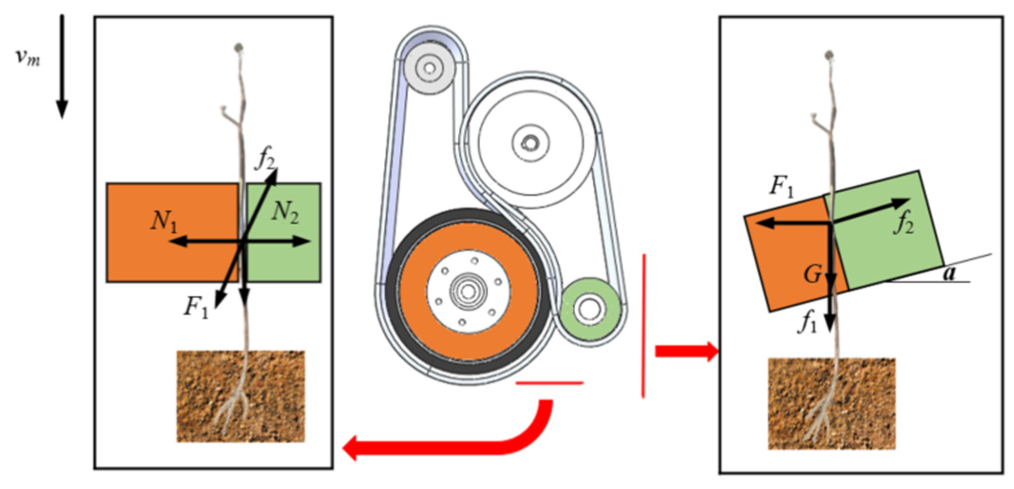
2.4. Clamping-Type Lifting Mechanism Lifting Mechanism Analysis

The clamping-type lifting mechanism is unilateral in conveying after rotary plucking. The active pinch roller is driven by a hydraulic motor to rotate, and under the action of static friction, the active pinch roller drives the rubber belt to rotate, and pluck and convey the cotton stalks.
The mechanism, using the front suspension fixed in front of the tractor operation, can prevent the tractor forward process on the cotton stalks plant growth state damage. As a result of the consideration of cotton planting for wide and narrow spacing, the design of the clamping stroke is relatively long; in order to avoid blocking the cotton stalks, and to ensure that the acceleration of the cotton stalks via the pulling and conveying is high enough, the clamping mechanism in the pulling stage has to pull out at the moment of the cotton stalks’ extraction. The force is shown in Figure 5.
a 2 = F 2 + N 3 N 4 m ,
a 2 x = μ f 3 cos β m a 2 y = f 5 0 J 2 π η r k h d h G 2 m ,
where β is the nip rollers and horizontal line angle (°), F2 is the push of the gripper mechanism forward against the cotton stalks (N), N3 is the squeezing force of the front nip roller belt on the cotton stalks (N), N4 is the squeezing force of the rear nip roller belt on the cotton stalks (N), f3 is the friction of double belts on cotton stalks (N), f4 is the soil resistance during lifting (N), f5 is the overcome the upward friction of the straw’s own mass (N), a2 is the acceleration in the forward direction of the clamping mechanism (m/s2), a2x is the acceleration in the horizontal direction at the moment of straw uplifting (m/s2), a2y is the acceleration in the vertical direction at the moment of lifting of the cotton stalks (m/s2), and G2 is the cotton Straw Gravity (N).
According to the Formulae (9) and (10), the faster the acceleration in the forward direction of the mechanism, the shorter the time that the cotton stalks are clamped, and the pulling direction is basically perpendicular to the forward direction, which is easy to lead to a tugging fracture in the cotton stalks not yet completely detached from the soil anchorage when the mechanism is forward. The greater the acceleration of the active pinch roller wheel, the greater the acceleration in the vertical direction at the moment of plucking the cotton stalks, and the easier it is to pull off the cotton stalks.
In the clamping-type lifting mechanism in the cotton field operation, the greater the acceleration in the forward direction, the higher the operating efficiency and the more cotton stalks will enter the pinch roller rubber gap. But, when the acceleration in the forward direction of the mechanism is less than the acceleration of the active pinch roller wheel, the cotton stalks are too long to be discharged in a timely manner, which will result in the straw not being transported in a timely manner and making them prone to cause clogging.

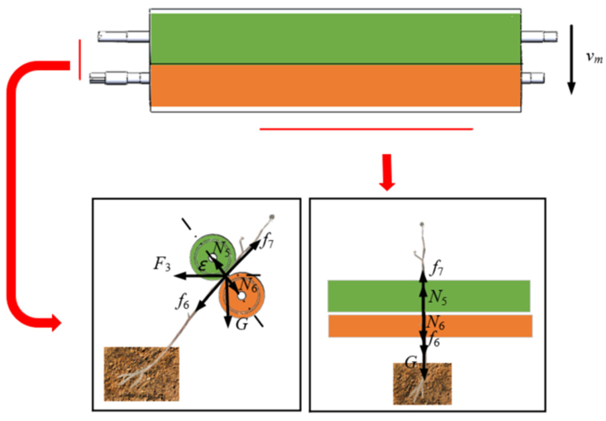
2.5. Cross Roller Drawing Mechanism Analysis of Pulling Mechanism

The cross roller drawing mechanism adopts the rear traction mode to hook up on the tractor, and the tractor power output shaft provides power for it. The agency utilizes the traction force generated by the pinch rollers rotating and pulling in opposite directions to complete the operation, as when the cotton is not planted widely, but instead in particularly narrow rows, a dense planting mode can be used for the cross roller operation width of 1250 mm. In a single pass, it can extract four rows of cotton stalks, with high operational efficiency.
A separately installed straw pressure mechanism will be bent to the upper and lower pinch roller gap, the top of the cotton straw, through the pulling rollers rotating in the opposite direction of the traction, then feed into the pinch rollers. Then, the cotton straw of the pinch rollers, as well as the backward pulling force pull up the cotton stalks of the whole plant, and are thrown back to the surface of the ground.
For the cross roller drawing mechanism during the pulling operation, the force analysis is shown in Figure 6. Because the cotton stalks from the top of the tip directly feed into the pinch roller plucking, plucking the moment of the horizontal direction of the acceleration is negligible; plucking the moment the cotton stalks are in the vertical direction of the force has the following relationship:
f 7 f 6 F 3 cos ( π 2 ε ) G 3 cos ε = m a 3 y ,
a 3 y = f 7 ( 0 J 2 π ρ z k 1 h 1 d h 1 + F 3 sin ε + G cos ε ) m ,
where ε is the nip rollers and horizontal line angle (°), F3 is the cross-roller mechanism forward thrust on cotton stalks (N), G3 is the cotton Straw Gravity (N), N5 is the squeezing force of the rubber band of the upper stalk puller on the cotton stalks (N), N6 is the squeezing force of the rubber band of the lower stalk puller on the cotton stalks (N), f7 is the friction of upper and lower nip rollers on cotton stalks (N), f6 is the soil resistance during lifting (N), a3y is the acceleration in the vertical direction at the moment of lifting of the cotton stalks (m/s2), and h1 is the height of the culm clamping area from the ground (mm).
Through the above analysis and calculation, it can be concluded that the plucking force of the clamping-type lifting mechanism is the largest of the three (the combined acceleration of the cotton stalks by the plucking force is directly proportional to the plucking force), but the rubber belt transverse clamping stroke is large, the plucking time is long, and the lateral conveying of cotton stalks is easy to cause tugging off, while conveying the cotton stalks can cause blockage; the cross roller drawing mechanism plucking force is second only to the clamping-type lifting mechanism, and the cross roller drawing mechanism of the simple structure does not require a feed to the line. The upper and lower pinch roller pulling force can be rotated to ensure the stability of the pulling; in the field operation, conditions are complex, and occasionally there is pull off leakage, for example, when some of the cotton stalks fall down, it is easy for the cotton picker operation to cause leakage of pulling. Furthermore, cotton picker operation can partially break the cotton stalks, and it is easy to cause the pull off phenomenon in the process of pulling. The wrapping-type lifting mechanism pulling force is the smallest of the three. Due to the use of the active and passive cross-arrangement of the pulley flexible belt wrapped lifting mode, with a longer pulling path stroke, there is a certain protective effect on the pulling of cotton stalks, effectively reducing the amount of damage to the cotton stalks’ xylem structure caused by the pulling rate. But, if the pulling of the culms operating speed is too fast, it is impossible to avoid the phenomenon of leakage of the pulling of cotton stalks from occurring.

2.6. Comparative Test of Pinch Roller-Type Extraction Mechanism

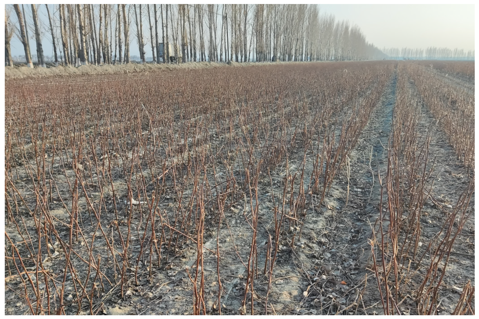
2.6.1. Test Condition

The theoretical analysis and comparison of the force situation on three different structures of cotton stalk pulling mechanisms have been conducted. In order to analyze the relationship between the force situation at the moment of stalk lifting and the operational effectiveness of the pulling mechanism, field comparative experiments were carried out on the devices equipped with three different structures of cotton stalk pulling mechanisms. These experiments were undertaken in the demonstration area of the integrated pilot project for research, development, manufacturing, and promotion of agricultural machinery in Yuli County, Bayingolin Mongol Autonomous Prefecture, Xinjiang, China (as shown in Figure 7 before the experiment), operated by Jifei Company’s Super (Location: Yuli County, China) Cotton Field, located on the northern side of the 802 km mark in the direction of Kuwei on National Highway 218.
Cotton stalks were planted in the test site with a row spacing of 760 mm, a plant spacing of 200 mm, and a plant height of 900~1200 mm. The test was conducted on 14–16 November 2022. The cotton field was planted with wide and narrow rows in an under-membrane drip irrigation planting pattern (660 mm + 100 mm). The cotton variety was Xinluzhong No. 66, and the cotton stalks had a water content of 55~57% and a diameter of about 12 mm (50 mm at the upper end of the ground surface). The cotton was harvested. The land was leveled sandy soil, where the soil water content was 14%, the soil pulling resistance was 500~800 N with an average of about 650 N, the soil hardness was 4.5~5.5 kg/cm2, and the drip irrigation belt was recovered. The machine operating speed was 2.5 km/h, with supporting power provided by the Dongfanghong LX804 (Manufacturer: YTO Group, Luoyang City, Henan Province, China) tractor (engine nominal power of 59 kW). In order to ensure that have the same ground clearance, the pulling point distance from the ground was 50 mm. See Figure 8 for the three different types of pinch roller class institutions pulling test results.

2.6.2. Test Indicators and Methods

In order to compare the pulling effect of the three different types of pinch roller pulling institutions, with reference to China Standards GB/T5262-2008 [25] “General Provisions on the Determination of Testing Conditions for Agricultural Machinery” and DB65/T4580-2023 “Quality of Cotton Straw Removal Machinery Operations”, a local standard of China, we selected the rate of missed pulling of cotton stalks and pulling breakage rate as the evaluation indexes. The test-selected operating length was 450 m and the operating width was 180 m, on the relatively flat terrain of the cotton field. The test object was divided from the nine test object areas, where the three kinds of pinch roller-type cotton straw pulling mechanisms each performed three repetitions of the test. From each of the test object areas, five test points were selected (with a unit area of 1 m × width of the operation); before the test, the statistics of each test area indicate the number of cotton stalks for each of the A, respectively. Before the test, the number of cotton stalks in each test area was counted as A. The number of cotton stalks omitted from the test points of the three different pinch-roller-types of cotton stalk pulling organizations was calculated as Am, and the number of cotton stalks broken was calculated as Ab.
In order to test the effect of the different types of pinch roller cotton stalk pulling mechanisms, the test area of the leakage rate of cotton stalks test point N1 and the cotton stalks pulling rate N2 were used as an evaluation index; the leakage rate of cotton stalks N1 and the cotton stalks pulling rate N2 is calculated as in Equation (13)
N 1 = A m A × 100 % N 2 = A b A × 100 % ,
And, taking the standard deviation of the mean value of the data of cotton straw leakage rate and cotton straw pulling breakage rate at each testing point, to indicate the degree of high and low pulling performance of the mechanism, we can see the relevant measurement data as shown in Table 1 and Table 2.

3. Results and Discussion

After the field comparison test of the three different types of pinch rollers, the evaluation indexes of the cotton stalk pulling performance of the three types of mechanisms are shown in Figure 9, Figure 10 (Version number of the software: Origin 2018) and Table 1 and Table 2 below, respectively.
As can be seen from Figure 9, for the leakage rate, the cross roller drawing mechanism extraction mechanism has a small leakage rate and high stability, followed by the wrapping-type lifting mechanism, and the clamping-type lifting mechanism, which shows an unstable state and large fluctuation. As can be seen in Figure 10, for the breakage rate, the highest breakage rate and test data fluctuations are found in the clamping-type lifting mechanism, whereas the wrapping-type lifting mechanism and cross roller drawing mechanism breakage rate fluctuation trends are more similar, although the latter fluctuation is smaller.
From the test data (Table 1 and Table 2) and field operation comparison of the actual results, it can be seen that the cross roller drawing mechanism X3 operation of the standard deviation has a leakage rate mean value of 0.43%, which is much smaller than the wrapping-type lifting mechanism X1 operation of the standard deviation of the leakage rate mean value of 0.83%. The average value of the standard deviation of the leakage rate of the clamping-type lifting mechanism X2 is 0.59%, which is better than the average value of the standard deviation of the leakage rate of the wrapping-type lifting mechanism X1 of 0.83%, and the gap between the leakage rate and the leakage rate of the cross roller drawing mechanism X3 is small. The average value of the standard deviation of pulling rate of the clamping-type lifting mechanism X2 is 1.79%, the highest, and the average value of the standard deviation of pulling rate of the wrapping-type lifting mechanism X1 is 1.48%, which is the second. The average value of the standard deviation of the pulling rate of the cross roller drawing mechanism X3 is 0.49%, the lowest. The cross roller drawing mechanism X3 average leakage rate is only 4.55%, and the average plucking rate is only 7.55%. There is no congestion of cotton stalks in the process of work, and the work process is smooth, although the cross roller drawing mechanism X3 is not the largest in the theoretical analysis of the starting pulling force, but with the wrapping-type lifting mechanism X1 and the cross roller drawing mechanism X3, compared to the top of the tip of the stalks from the roots in the longitudinal extraction of the unique plucking method, the first two institutions transversely plucked cotton stalks in the longitudinal direction. Compared with the first two institutions, the transverse plucking of cotton stalks in the lower part of the plucking performance indicators are better; the best effect of the whole straw plucking operation of cotton stalks, the horizontal roller-type plucking mechanism, can effectively solve the problem of whole straw plucking and the harvesting of cotton stalks, so it can be consequently used in actual cotton production.

4. Conclusions

1.
The size of the plucking force of the pinch roller-type straw pulling mechanism is directly proportional to the acceleration in the vertical direction at the moment of plucking, and the larger the combined acceleration is, the more the maximum static friction resistance to plucking resistance is. In the comparison of the three kinds of structure of the pinch roller-type cotton straw pulling mechanisms, the analysis and calculation results indicate that the clamping-type lifting mechanism pulling force is larger, but the initial feeding point of pulling is high and has low requirements. The wrapping-type lifting mechanism of the pulling force is small, while the cross roller drawing mechanism of the pulling force is in the middle, with most of its major advantages being the maximum width of the working width and the fact that it does not need to work in rows.
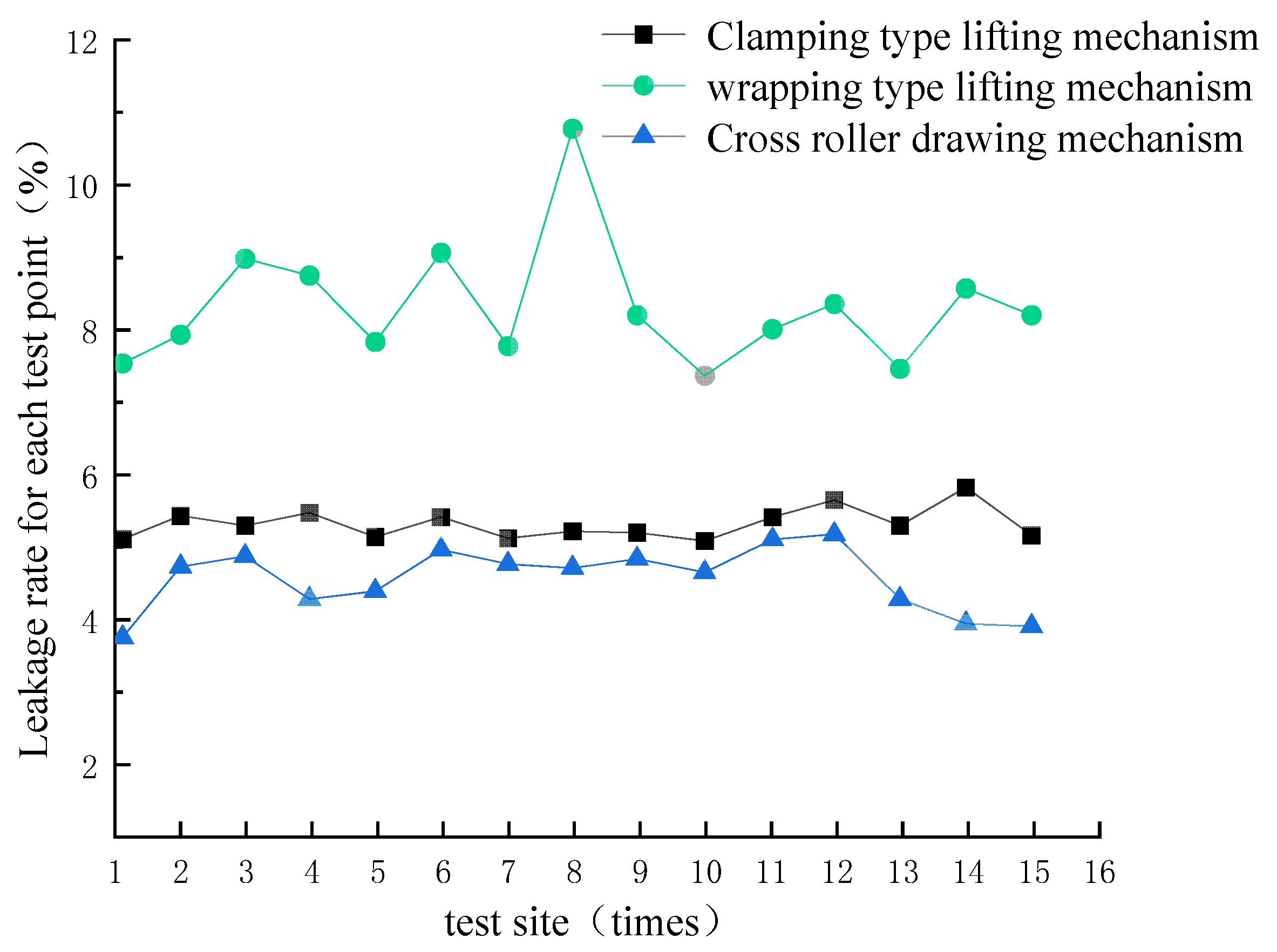
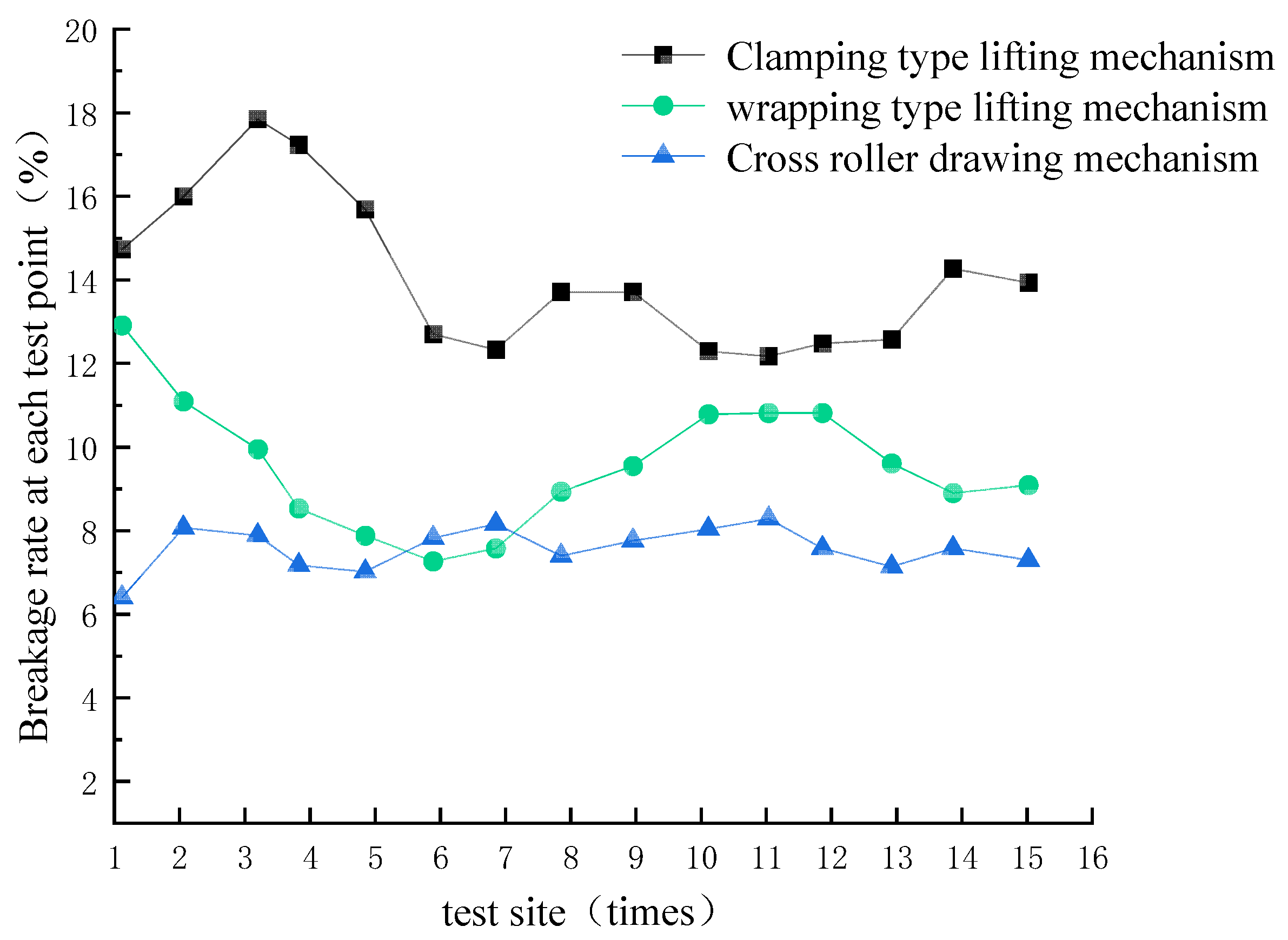
2.
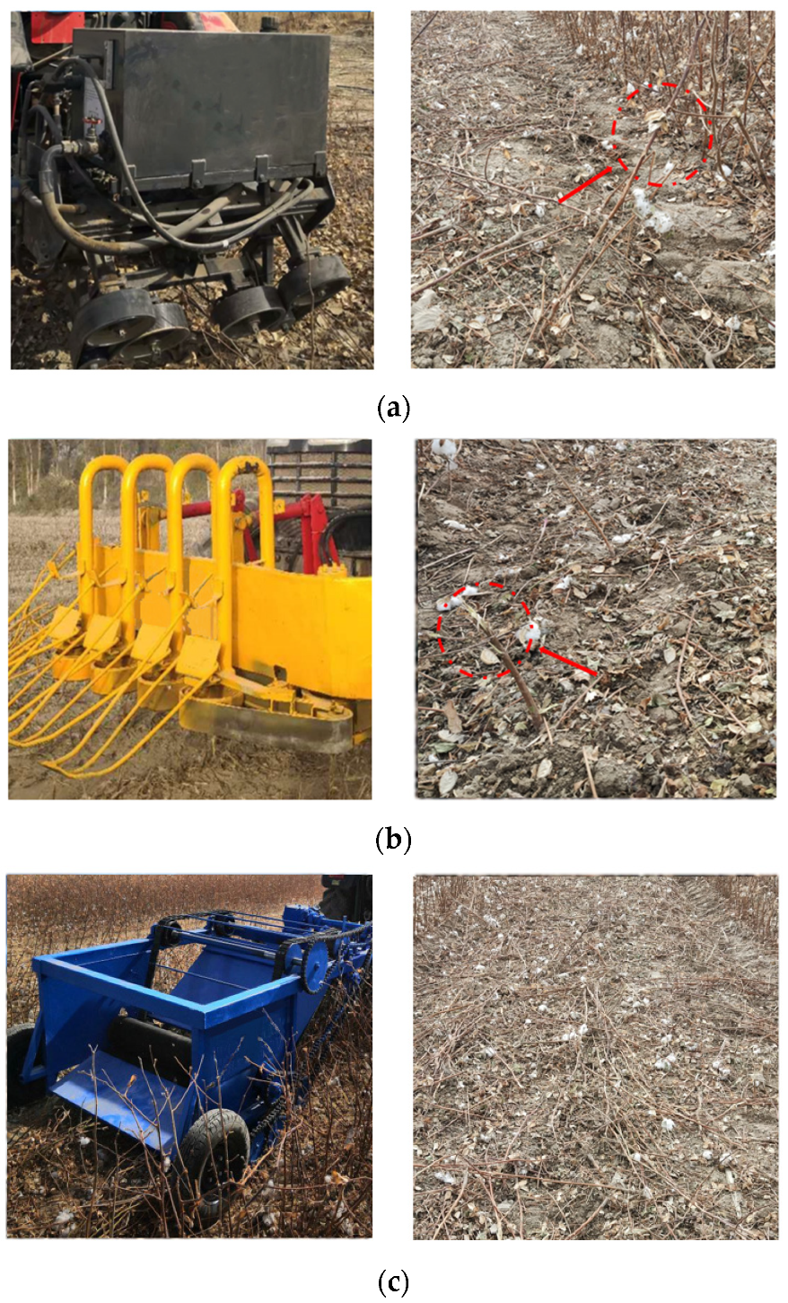
The wrapping-type lifting mechanism, clamping-type lifting mechanism and cross roller drawing mechanism are three different kinds of plucking mechanisms installed in the test device to carry out the test of cotton stalk pulling. The test data of the X1, X2, X3 plucking mechanisms of the standard deviation of the leakage rate are 0.83%, 0.59%, 0.43%, the standard deviation of the pulling rate of the mean value are 1.48%, 1.79%, 0.49%, respectively. Through the field test, we see that the best mechanism is the cross roller drawing mechanism; although the pulling force is not the largest among the three, the cross roller drawing mechanism leaks less cotton stalks. The average leakage rate of cotton stalks is only 4.55%, and does not block the stalks. The measurement of the cotton stalks whole straw plucking mechanism as an indication of the quality of the operation is another key point. When the cotton straw plucking rate is low enough, the reason for this is that after the plucking of broken cotton stalks, they basically cannot enter the pinch roller gap, directly affecting the total amount of cotton stalks whole straw plucking. So, in order to pursue a high quality of operation regarding the straw plucking mechanism, reduce the average leakage rate of the cotton stalks whole straw plucking, and the average rate of pulling off the rows during work, using the cross roller-type pulling mechanism for whole straw pulling and harvesting after autumn is the best method.
3.
At present, the domestic and foreign cotton stalk plucking, planning, digging, shoveling, and cutting, have reached a high theoretical and technological level, but are not applicable to the current planting mode of cotton stalk plucking production needs. The use of pinch roller-type in institutions means that soil plucking is not completed to ensure a low plucking breakage rate and a low leakage plucking rate during harvesting, but instead is used to completely harvest cotton stalks, in order to maximize the use of biological resources in the later stage. In this paper, we mainly study the influence of different pulling mechanisms on the performance of cotton stalk pulling, under the condition of long time operation, and the mechanical property failure caused by heat generation that exists in the pinch roller pulling parts. Subsequent research should also be carried out for the material characteristics of the pulling parts.

Author Contributions

Conceptualization, Y.W. and J.Z.; methodology, Y.W., J.Z. and Y.H.; software, Y.W. and J.Z.; validation, Y.W., J.Z., Y.H. and Z.W.; formal analysis, Y.W. and J.Z.; investigation, Y.W., J.Z., Y.H. and J.L.; data curation, Y.W., J.Z. and Y.H.; writing—original draft preparation, Y.W., J.Z. and Y.H.; writing—review and editing, Y.H., J.Z. and S.S.; visualization, Y.W., J.L. and S.S.; supervision, J.Z.; funding acquisition, J.Z. All authors have read and agreed to the published version of the manuscript.

Funding

This work was financially supported by the National Natural Science Foundation of China (52365038), the National Natural Science Foundation of China (51865058) and the China Agricultural Science and Technology Extension and Service Program (NTFW-2022-17).

Institutional Review Board Statement

Not applicable.

Data Availability Statement

Data are contained within the article.

Acknowledgments

The authors thank the editor and anonymous reviewers for providing helpful suggestions for improving the quality of this manuscript.

Conflicts of Interest

The authors declare no conflicts of interest.

References

  1. Zhao, W.; Xie, J.; Wang, Z.; Gao, Q.; Chen, M. Investigation of mechanical properties of cotton stalk based on multi-component analyses. Int. Agrophys. 2022, 31, 7–11. [Google Scholar] [CrossRef]
  2. Pan, Z. Research on Cotton Stalk Harvester Based on Double Roller Type. Adv. Mater. Res. 2014, 945–949, 286–289. [Google Scholar] [CrossRef]
  3. Baker, K.D.; Hughs, E.; Foulk, J.A. Cotton Quality as Affected by Changes in Spindle Speed. Appl. Eng. Agric. 2010, 26, 363–369. [Google Scholar] [CrossRef]
  4. Han, L.; Francis, K.; Mao, H.; Hu, J. Design and Tests of a Multi-pin Flexible Seedling Pick-up Gripper for Automatic. Appl. Eng. Agric. 2019, 6, 949–957. [Google Scholar] [CrossRef]
  5. Ghahraei, O.; Ahmad, D.; Khalina, A.; Suryanto, H.; Othman, J. Cutting Tests of Kenaf Stems. Trans. ASABE 2011, 54, 51–56. [Google Scholar] [CrossRef]
  6. Gupta, R.; Singh, S.; Sharda, V. Study on mechanical properties of cotton stalks in relation to plant pulling machinery. J. Res. 2007, 44, 66–69. [Google Scholar]
  7. Kumar, V.J.F.; Parvathi, S. Ergonomics of rural women for selected dry farming operations. Madras Agric. J. 2022, 29, 43–50. [Google Scholar]
  8. Kirkpatrick, C.; Viollier, P. A polarity factor takes the lead in chromosome segregation. EMBO J. 2010, 29, 3035–3036. [Google Scholar] [CrossRef]
  9. Sarkari, M.; Minaee, S. Evaluation of a cotton stalk puller performance. Am.-Eurasian J. Sustain. Agricult. 2008, 2, 19–24. [Google Scholar]
  10. Kumar, C.; Prakash, K.; Reddy, S. Development of Cotton stalk harvesting machine for ex-situ application. Ecol. Environ. Conserv. 2022, 16, 154–165. [Google Scholar] [CrossRef]
  11. Dong, S.; Wang, F.; Qiu, Z. Design and experiment of self-propelled cotton stalk picking harvester. Ecology. Trans. Chin. Soc. Agric. Mach. 2010, 41, 99–102. [Google Scholar]
  12. Xie, J.; Wu, S.; Cao, S. Design and testing of clamping roller type cotton stalk extraction device. Trans. Chin. Soc. Agric. Mach. 2023, 54, 101–111. [Google Scholar]
  13. Xu, X.; Li, L.; Ren, B. Dynamic Characterization of Spatial Axis Cross-Angle Herringbone Planetary Gear System. J. Mech. Eng. 2023, 59, 141–150. [Google Scholar]
  14. Cai, J.; Zhang, J.; Ye, T. Design and testing of a gripper belt type cotton stalk harvester. Trans. Chin. Soc. Agric. Eng. 2020, 51, 86–98. [Google Scholar]
  15. Hou, J.; Li, C.; Lou, W. Design and Test of Floating Clamping Device forGarlic Combine Harvester. Trans. Chin. Soc. Agric. Mach. 2023, 54, 137–145. [Google Scholar]
  16. Zhang, G.; Li, Y.; Li, Z. Measuring system of cotton stalk real-time pull force in the field based on LabVIEW. In Proceedings of the ASABE 2014 Annual International Meeting, Montreal, QC, Canada, 13–16 July 2014; p. 141912493. [Google Scholar] [CrossRef]
  17. Chen, X.; Li, Y.; Li, Z. Parameter Calibration of Discrete Element Model for Cotton Rootstalk–Soil Mixture at Harvest Stage in Xinjiang Cotton Field. Agriculture 2023, 13, 1344. [Google Scholar] [CrossRef]
  18. Zhang, B.; Liang, R.; Li, Z. Test and Analysis on Friction Characteristics of Major Cotton Stalk Cultivars in Xinjiang. Agriculture 2022, 12, 906. [Google Scholar] [CrossRef]
  19. Zhang, J.; Rui, Z.; Cai, J. Design and testing of a front-mounted belt clamping and conveying cotton stalk puller. Trans. Chin. Soc. Agric. Mach. 2021, 52, 77–152. [Google Scholar]
  20. Dong, X.; Zhang, Z. Soil properties, root morphology and physiological responses to cotton stalk biochar addition in two continuous cropping cotton field soils from Xinjiang, China. PeerJ 2022, 10, e12928. [Google Scholar] [CrossRef]
  21. Li, Y.; Cheng, C.; Xu, L. Design and experiment of baler for 4L-4.0 combine harvester of rice and wheat. Trans. Chin. CSAE 2021, 32, 29–35. [Google Scholar]
  22. Zhang, J.; Gao, Z.; Cai, J. Design and test of transverse-axis counter-roller type cotton stalk pulling device. Trans. Chin. Soc. Agric. Eng. 2021, 37, 43–52. [Google Scholar]
  23. Tang, Z.; Han, Z.; Gan, B. Design and testing of a harvesting stand for cotton straw pulling in the wrong row. Trans. Chin. Soc. Agric. Mach. 2010, 41, 80–85. [Google Scholar]
  24. Zhang, B.; Chen, X. Cotton stalk restitution coefficient determination tests based on the binocular high-speed camera technology. Int. J. Agric. Biol. Eng. 2022, 28, 75–92. [Google Scholar] [CrossRef]
  25. GB/T 5262-2008; General Provisions on Methods for Determining Test Conditions for Agricultural Machinery. Standardization Administration of China: Beijing, China, 2008.
Figure 1. Schematic diagram of the picking process of the nip roller type cotton stalk whole plant picking mechanism.
Agriculture 14 00506 g001
Figure 2. Nip-roller-type cotton straw whole plant plucking mechanism type: (a) wrapping-type lifting mechanism; (b) clamping-type lifting mechanism (c) cross roller drawing mechanism.
Agriculture 14 00506 g002
Figure 3. Nip roller type cotton straw whole plant plucking mechanism starting and pulling instant movement diagram.
Agriculture 14 00506 g003
Figure 4. Force analysis diagram of wrapping-type lifting mechanism.
Agriculture 14 00506 g004
Figure 5. Clamping-type lifting mechanism lifting force analysis diagram.
Agriculture 14 00506 g005
Figure 6. Cross roller drawing mechanism pulling force analysis diagram.
Agriculture 14 00506 g006
Figure 7. Jifei Company’s Super Cotton Field.
Agriculture 14 00506 g007
Figure 8. Comparison of the lifting and pulling performance of the pressure roller-type cotton stalk picking mechanisms in field tests: (a) wrapping-type lifting mechanism pulling performance test; (b) clamping-type lifting mechanism pulling performance test; (c) cross roller drawing mechanism pulling performance test.
Agriculture 14 00506 g008
Figure 9. Comparison of the leakage rate of three different types of clamping roller lifting mechanisms (wrapping-type lifting mechanism leakage rate is the highest).
Agriculture 14 00506 g009
Figure 10. Comparison of pullout rate of three different pinch roller-type pulling mechanisms (clamping-type lifting mechanism has the highest breakage rate).
Agriculture 14 00506 g010
Table 1. Cotton straw leakage rate index test results.
Pinch Roller-Type Stalk Pulling Mechanism TypeLeakage Rate for Each Test PointAverage Leakage Rate
(%) (Standard Deviation Mean)
Detection Point 1
(%)
Detection Point 2
(%)
Detection Point 3
(%)
Detection Point 4
(%)
Detection Point 5
(%)
wrapping-type
X1
17.537.938.988.747.838.32
(0.83)
29.067.7610.778.197.35
38.008.357.458.568.19
clamping-type
X2
43.105.425.295.465.135.18 (0.59)
55.415.115.215.195.07
65.405.645.295.825.15
cross roller
X3
73.744.724.864.274.384.55 (0.43)
84.954.754.704.824.64
95.105.174.273.933.89
Table 2. Cotton straw pulling rate index test results.
Pinch Roller-Type Stalk Pulling Mechanism TypeBreakage Rate at Each Test PointAverage Breakage Rate
(%) (Standard Deviation Mean)
Detection Point 1
(%)
Detection Point 2
(%)
Detection Point 3
(%)
Detection Point 4
(%)
Detection Point 5
(%)
wrapping-type
X1
112.9011.089.938.517.859.56 (1.48)
27.247.558.919.5310.76
310.7910.809.588.879.06
clamping-type
X2
414.7215.9817.8417.2315.6814.10 (1.79)
512.6812.3113.6913.7012.28
612.1612.4612.5614.2613.92
cross roller
X3
76.378.047.857.156.987.55 (0.49)
87.798.137.377.738.01
98.267.557.117.557.27
Disclaimer/Publisher’s Note: The statements, opinions and data contained in all publications are solely those of the individual author(s) and contributor(s) and not of MDPI and/or the editor(s). MDPI and/or the editor(s) disclaim responsibility for any injury to people or property resulting from any ideas, methods, instructions or products referred to in the content.

