
Study on Shifting Performance of Tractor Multi-Clutch under Different Engagement Rules

Abstract
1. Introduction
2. Structure and Mathematical Modeling of Engine and Power Shift Transmission
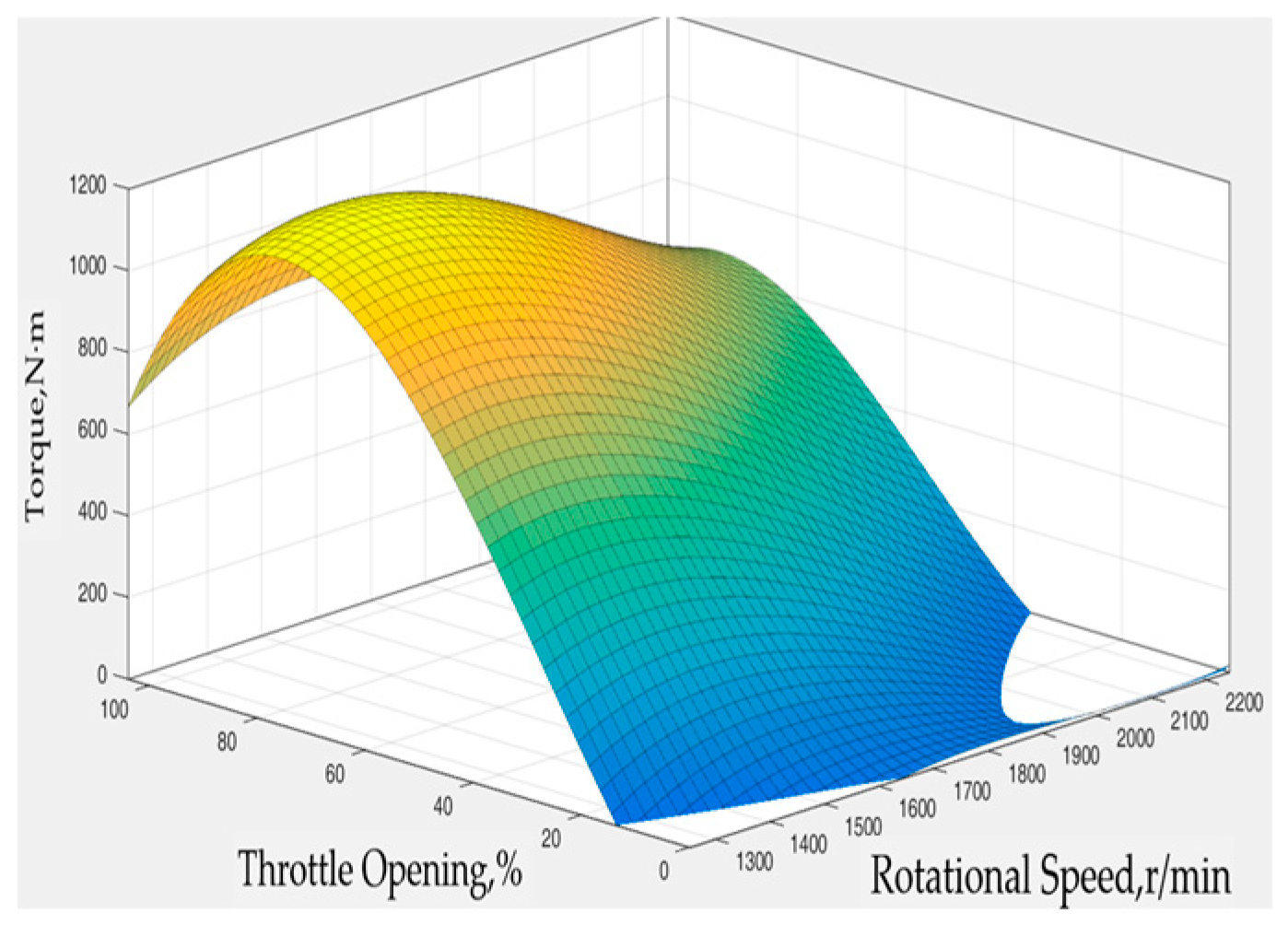
2.1. Engine Model
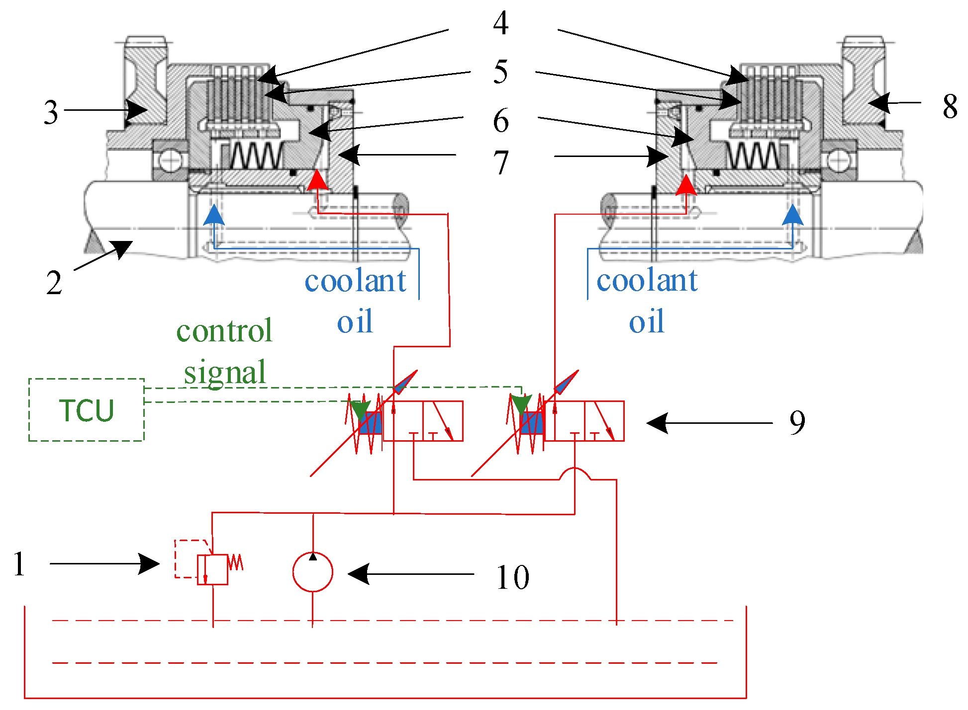
2.2. PST Structure
2.3. Power Shift Principle
3. Dynamic Analysis of Tractor Dynamic Shift Process
3.1. Switching Rule A
3.2. Switching Rule B
3.3. Switching Rule C
4. Combined Process Dynamic Modeling and Simulation
4.1. Model Construction
4.2. Evaluation Method of Shift Characteristics
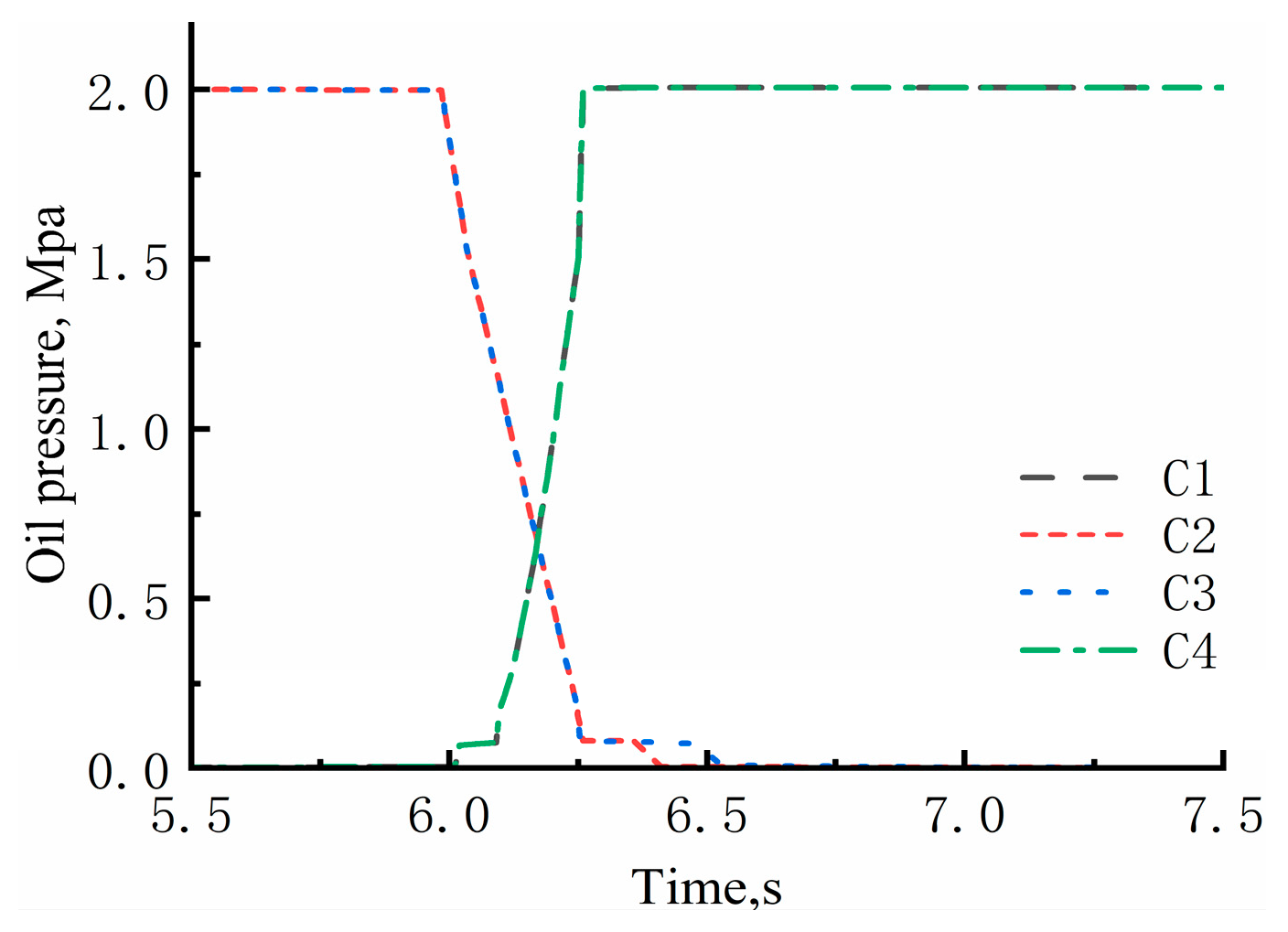
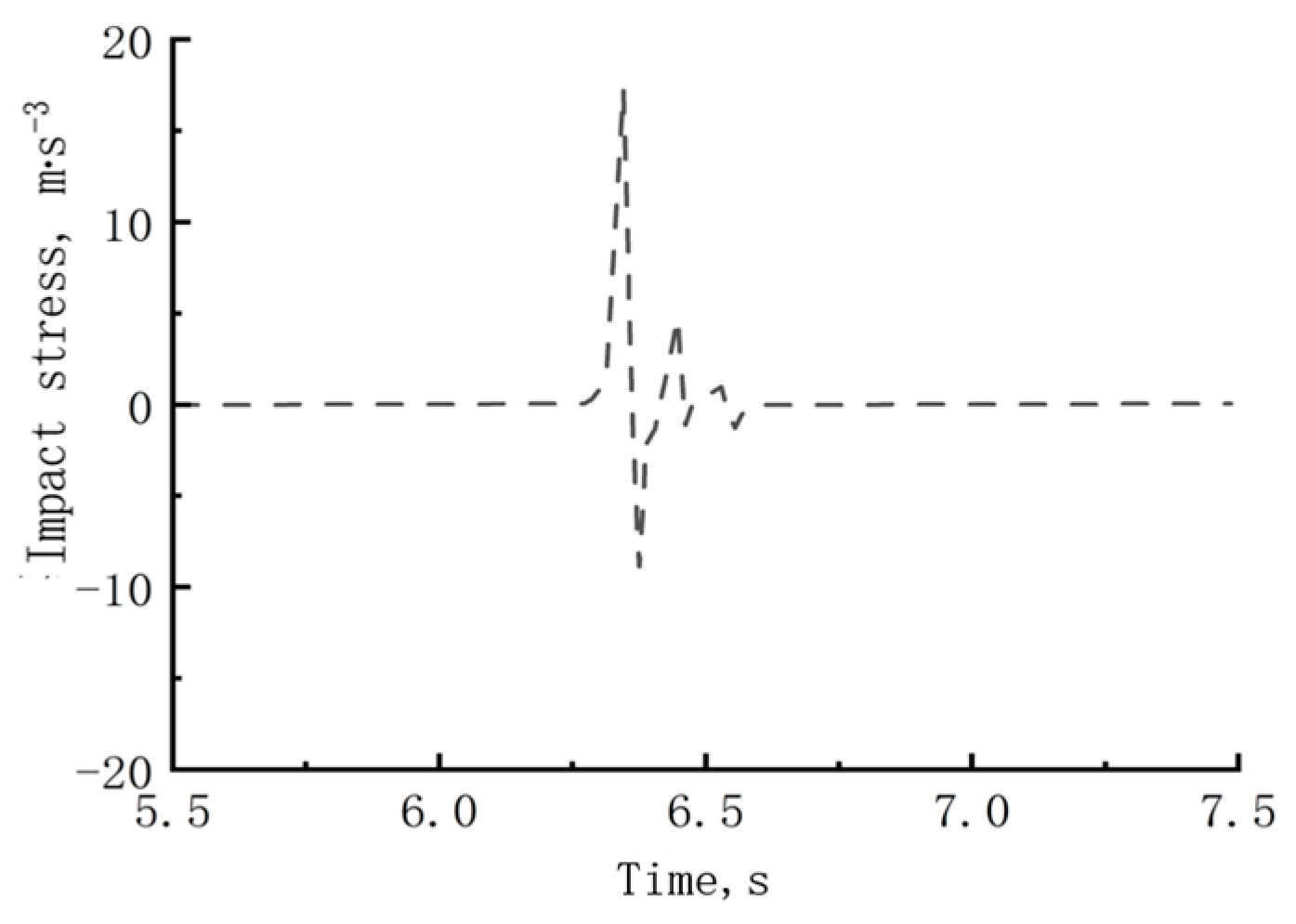
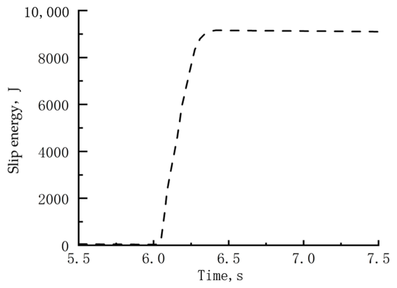
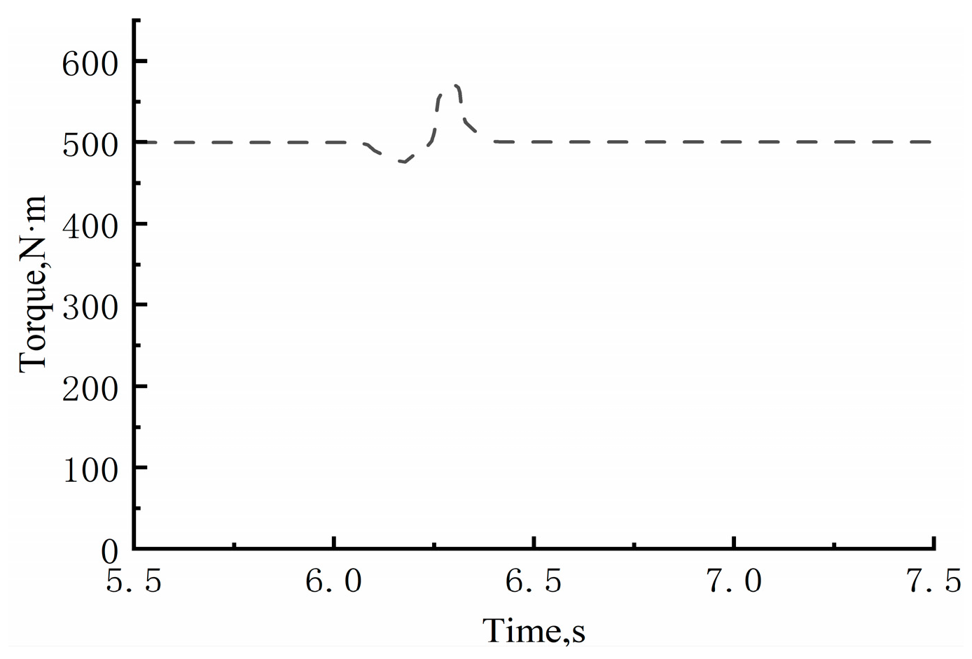
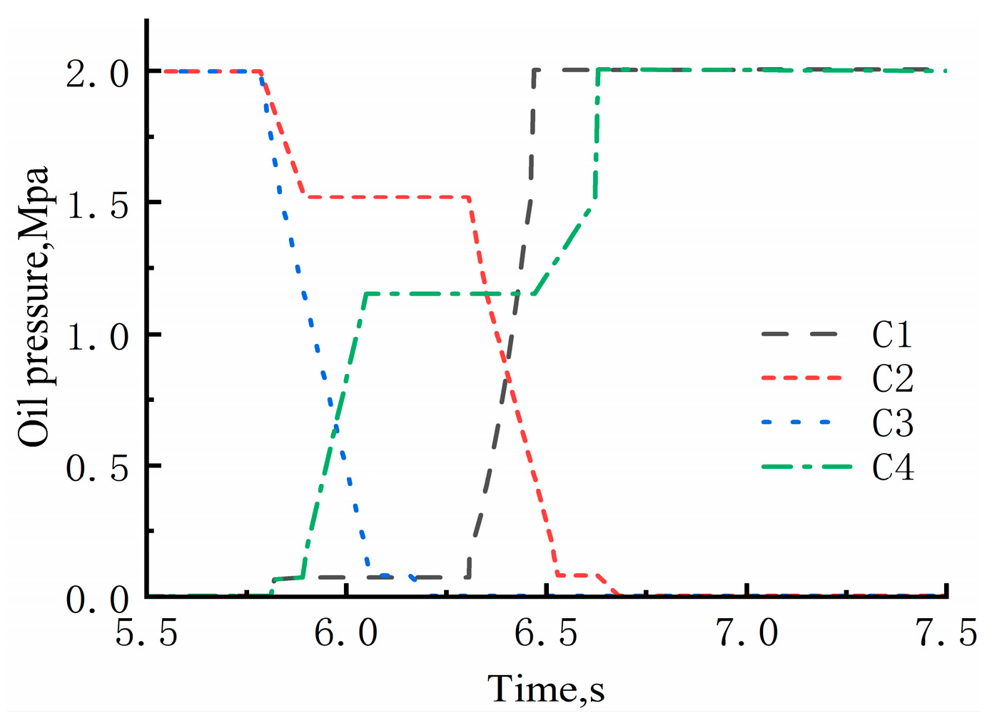
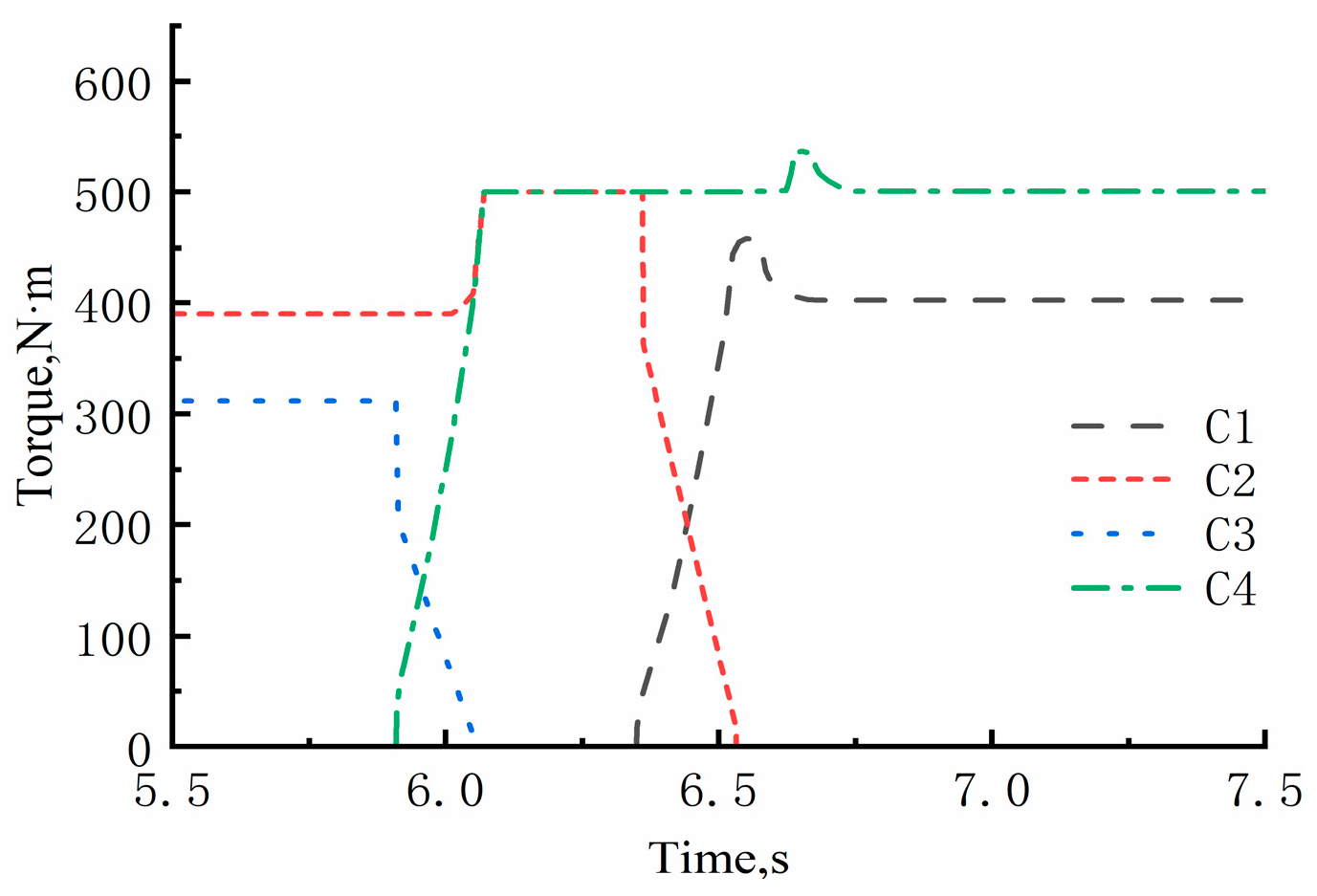
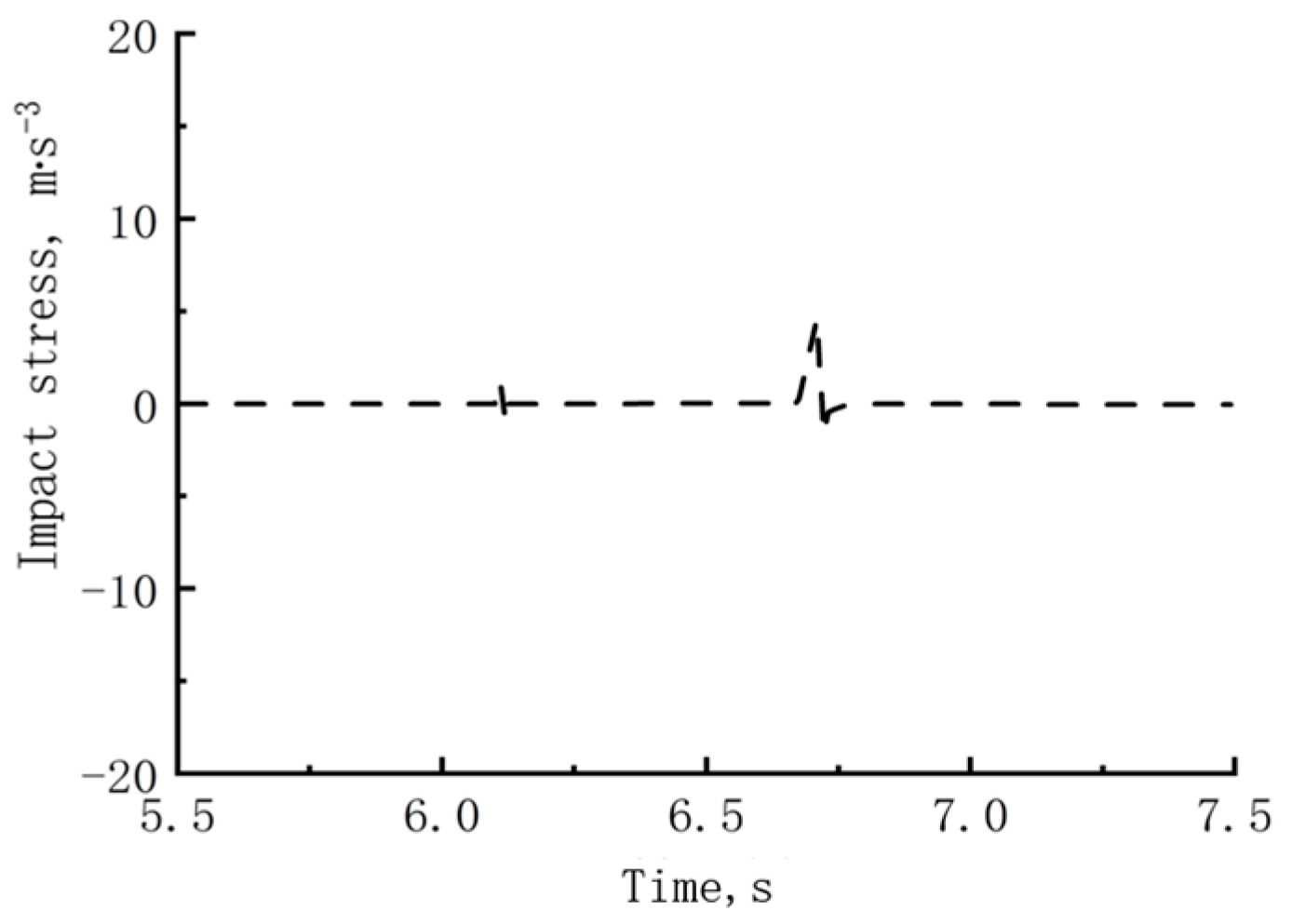
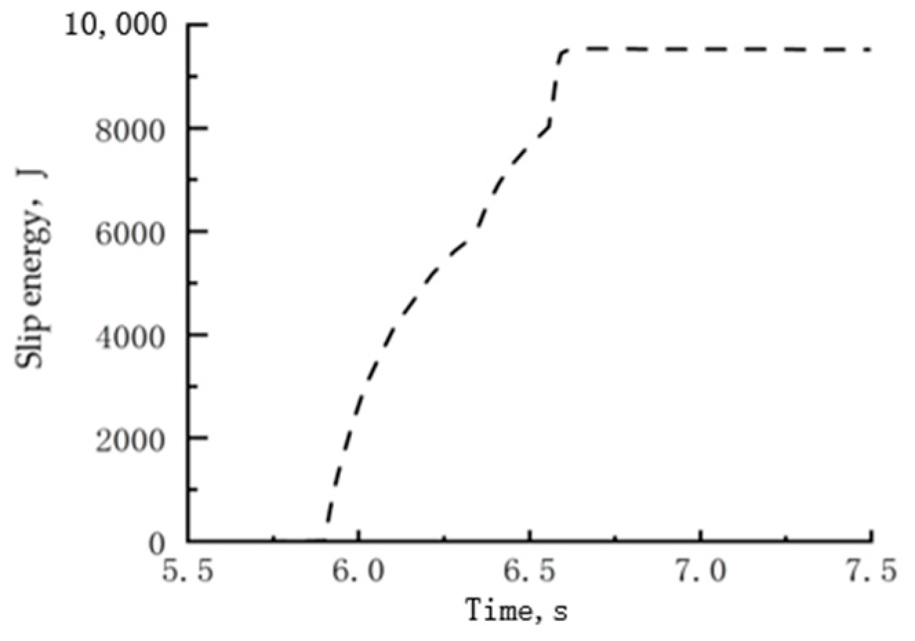
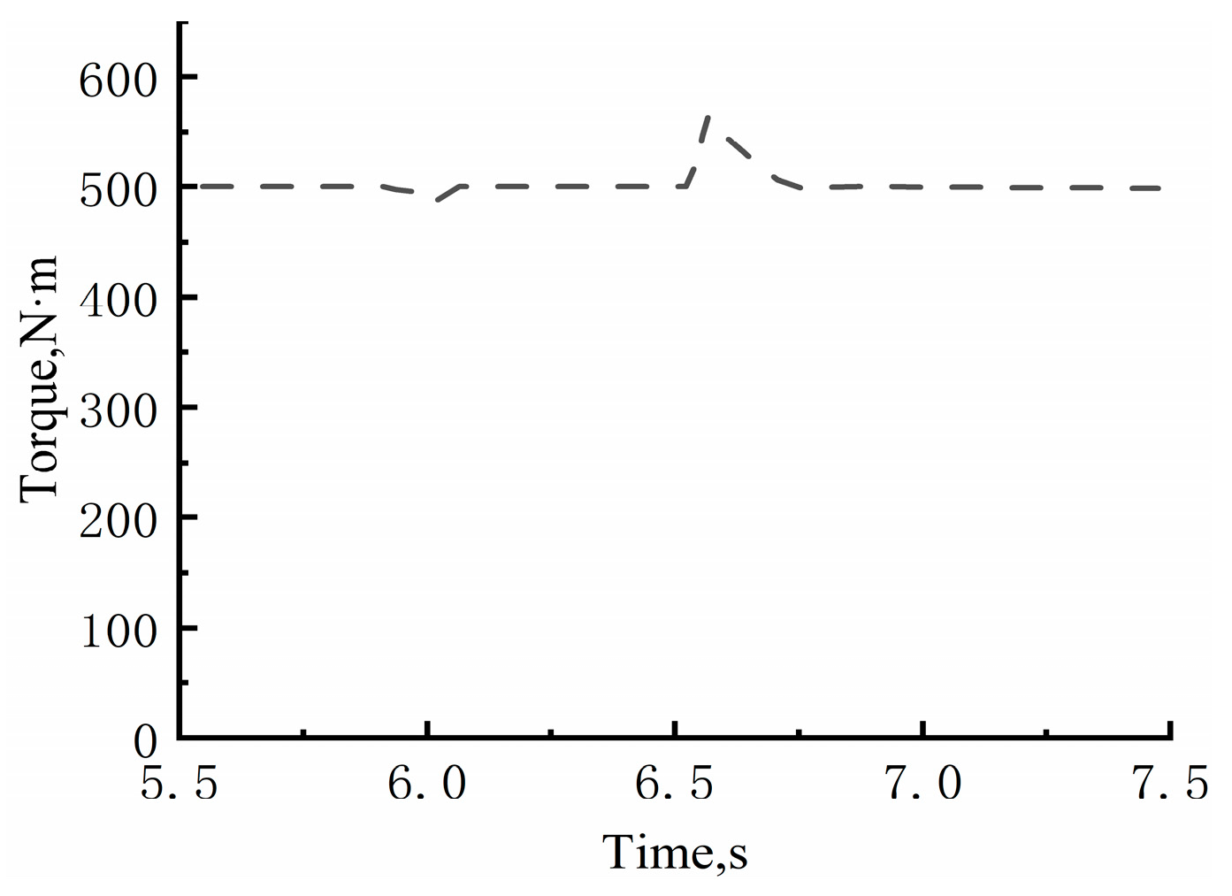
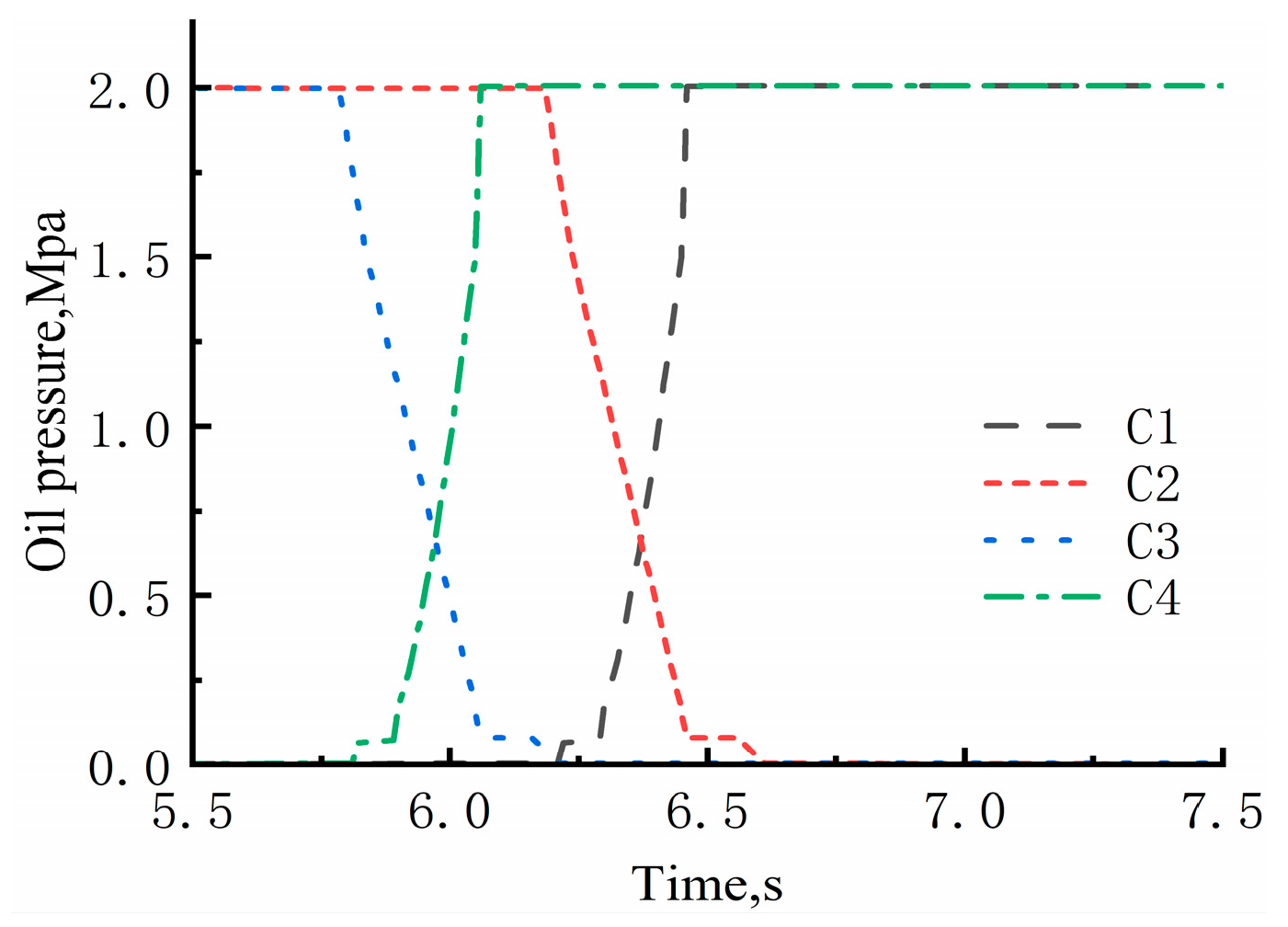
4.3. Analysis of Simulation Results
5. Conclusions
Author Contributions
Funding
Institutional Review Board Statement
Data Availability Statement
Conflicts of Interest
References
- Xie, B.; Wu, Z.; Mao, E. Development status and prospect of key technologies of agricultural tractor. Trans. Chin. Soc. Agric. Mach. 2018, 49, 1–17. [Google Scholar]
- Shi, F.; Ma, M.; Zhou, Y.; Hu, H. Power shift tractor gearbox off-line running-in test bench. Mod. Agric. Equip. 2022, 43, 26–30. [Google Scholar]
- Zhang, Y.; Xin, Z.; Du, Y.; Shao, M.; Sun, E.; Zhang, F. Rapid design method and software development of tractor gearbox box. Trans. Chin. Soc. Agric. Eng. 2020, 36, 49–55. [Google Scholar]
- Zhang, H.; Tian, J.; Chen, Z.; Xu, G.; Zhou, P. Study on hydraulic shifting characteristics of gearbox of engineering vehicle. Mech. Trans. 2015, 39, 173–176. [Google Scholar]
- Wang, Y.; Lu, L.; Sun, M.; Ni, H.; Yi, Y. Research on control system of tractor power shift transmission under CAN intelligent node. J. Chongqing Univ. Technol. (Nat. Sci. Ed.) 2022, 36, 245–250. [Google Scholar]
- Fu, S.; Zhang, Y.; Zhang, W.; Mao, E.; Wang, G.; Du, Y. PST shift strategy and hardware-in-the-loop test considering random load adaptive compensation. Trans. Chin. Soc. Agric. Mach. 2022, 53, 408–416. [Google Scholar]
- Fu, S.; Gu, J.; Li, Z.; Mao, E.; Du, Y.; Zhu, Z. Pressure control method of wet clutch of power shift gearbox based on MFAPC. Trans. Chin. Soc. Agric. Mach. 2020, 51, 367–376. [Google Scholar]
- Sun, C.; Si, T.; Zhu, M.; Yang, B. Research on power shift quality optimization based on wet clutch oil pressure segmentation control strategy. Chin. J. Agri. Mech. 2022, 43, 106–112+117. [Google Scholar]
- Sun, D.; Chen, X.; Li, B.; Yang, B. Dynamic control method of tractor power shift process based on genetic algorithm. J. Chongqing Univ. 2019, 42, 1–14. [Google Scholar]
- Zhang, Z.; Chen, J.; Yao, L.; Zheng, Y. Target torque control of two-speed DCT clutch based on GA-LQR. Mech. Trans. 2020, 44, 28–33. [Google Scholar]
- Zhu, S.; Wu, G. Simulation study on optimal control of shifting process of hydromechanical automatic transmission. Mech. Trans. 2014, 38, 15–19. [Google Scholar]
- Roozegar, M.; Angeles, J. Gear-Shifting in a Novel Modular Multi-Speed Transmission for Electric Vehicles Using Linear Quadratic Integral Control. Mech. Mach. Theory 2018, 128, 359–367. [Google Scholar] [CrossRef]
- Kim, S.; Oh, J.; Choi, S. Gear Shift Control of a Dual-Clutch Transmission Using Optimal Control Allocation. Mech. Mach. Theory 2017, 113, 109–125. [Google Scholar] [CrossRef]
- Xi, Z.; Zhou, Z.; Zhang, M.; Cao, Q. Research on shifting characteristics and control strategy of tractor power shift transmission. Trans. Chin. Soc. Agric. Mach. 2016, 47, 350–357. [Google Scholar]
- Mishra, K.D.; Srinivasan, K. Robust Control and Estimation of Clutch-to-Clutch Shifts. Control Eng. Pract. 2017, 65, 100–114. [Google Scholar] [CrossRef]
- Shi, X.; Xia, G. Research on shift control under traction conditions of high-horsepower tractor. J. Hefei Univ. Technol. (Nat. Sci. Ed.) 2019, 42, 601–607. [Google Scholar]
- Zheng, X. Research on Optimal Control Algorithm of Shifting Process of Hydromechanical Automatic Transmission for Off-Road Vehicles. Master’s Thesis, Jilin University, Changchun, China, 2018. [Google Scholar]
- Li, B.; Sun, D.; Hu, M.; Zhou, X.; Wang, D.; Xia, Y.; You, Y. Automatic Gear-Shifting Strategy for Fuel Saving by Tractors Based on Real-Time Identification of Draught Force Characteristics. Biosyst. Eng. 2020, 193, 46–61. [Google Scholar] [CrossRef]
- Tian, Y.; Ma, Y.; Wang, C. Study on shifting characteristics of tractor power shift gearbox. J. Agric. Mech. Res. 2020, 42, 226–230. [Google Scholar]
- Zhang, Z.; Wu, X.; Yang, C.; Zou, B. Research on precise control method of clutch torque in wet DCT shifting process. Chongqing Univ. Technol. (Nat. Sci. Ed.) 2023, 37, 8–18. [Google Scholar]
- Cao, Q. Research on Key Technology of Tractor PST Control System. Doctor’s Thesis, Xi’an University of Technology, Xi’an, China, 2018. [Google Scholar]
- Zheng, X.; Sun, W. Engine performance analysis and modeling based on MATLAB fitting toolbox. Shandong Indus. Technol. 2017, 18, 1–2. [Google Scholar]
- Yan, X. Research on Key Technologies of Virtual Test of Tractor Power Shift Drive Train. Doctor’s Thesis, Henan University of Science and Technology, Luoyang, China, 2020. [Google Scholar]
- Cai, Z.; Zhan, D. Research on multi-clutch shift control strategy of power shift transmission. Eng. Mach. 2022, 53, 8–13+7. [Google Scholar]
- Dang, H. Research on shift quality of dual clutch automatic transmission. Auto Time 2017, 10, 103–105. [Google Scholar]


| Parameters | Definition | Unit |
|---|---|---|
| Engine output torque | N·m | |
| , , , | Torque transmitted by clutch C1, C2, C3, C4 | N·m |
| Resistance moment of the wheel | N·m | |
| Engine crankshaft, flywheel, input solid shaft and associated gears and clutches C1, C2 driving disc equivalent moment of inertia | kg·m2 | |
| Equivalent moment of inertia of clutch C1 driven disk, solid shaft and clutch C3 driving disk | kg·m2 | |
| Equivalent moment of inertia of clutch C2 driven disc, solid shaft and clutch C4 driving disk | kg·m2 | |
| Equivalent moment of inertia of clutch C3 driven disk and drive gear | kg·m2 | |
| Equivalent moment of inertia of clutch C4 driven disk and solid shaft and associated gear | kg·m2 | |
| Equivalent moment of inertia of vehicle equivalent to wheel | kg·m2 | |
| Angular velocity of engine crankshaft | rad·s−1 | |
| , , , | Angular velocity of driven discs C1, C2, C3, C4 of the clutch | rad·s−1 |
| Angular velocity of the wheel | rad·s−1 | |
| The first gear transmission ratio | / | |
| The third gear transmission ratio | / | |
| The fourth gear transmission ratio | / |
| Gear | Clutch C1 | Clutch C2 | Clutch C3 | Clutch C4 |
|---|---|---|---|---|
| I | ◯ | × | ◯ | × |
| II | × | ◯ | ◯ | × |
| III | ◯ | × | × | ◯ |
| IV | × | ◯ | × | ◯ |
| Parameters | Unit | Value |
|---|---|---|
| Oil supply pressure | MPa | 2 |
| Hydraulic oil density | kg·m−3 | 850 |
| Hydraulic oil volume elastic modulus | Pa | 1.7 × 10⁹ |
| Equivalent mass of clutch piston | kg | 0.65 |
| Clutch piston outside radius | mm | 62.5 |
| Clutch piston inner radius | mm | 27.5 |
| Clutch spring stiffness | N·m−1 | 25,600 |
| Initial force of clutch return spring | N | 2150 |
| Clutch piston kiss point | mm | 2.8 |
| Initial volume of clutch cylinder | m3 | 2.27 × 10⁻⁴ |
| Number of clutch friction pieces | / | 6 |
| Clutch inlet diameter | mm | 6 |
| Clutch dynamic friction coefficient | / | 0.06 |
| Clutch static friction coefficient | / | 0.12 |
| Equivalent rotational inertia of the engine and flywheel | kg·m−2 | 0.6 |
| Equivalent rotational inertia of the transmission output shaft | kg·m−2 | 6 |
| Driving wheel radius, | m | 0.95 |
| Final gear ratio | / | 46.35 |
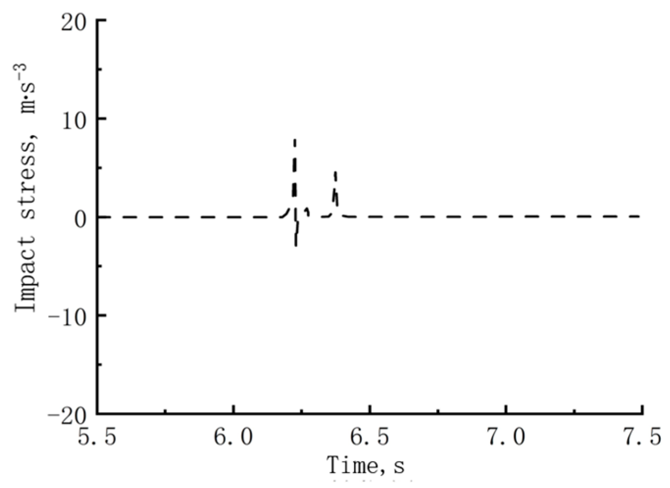
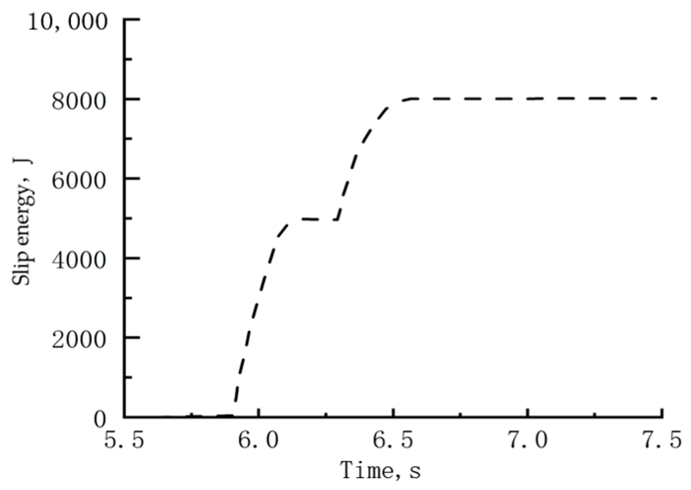
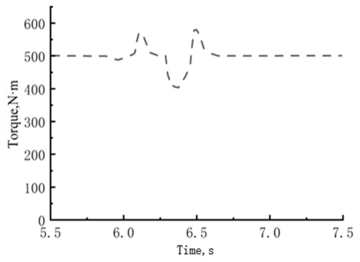
| Shift Time, s | Impact Stress, m·s−3 | Slip Energy, J | Minimum Output Torque, N·m | |
|---|---|---|---|---|
| Switching rule A | 0.7 | 17 | 9102 | 475 |
| Switching rule B | 0.9 | 4.8 | 9517 | 485 |
| Switching rule C | 0.85 | 8 | 8014 | 403 |
Disclaimer/Publisher’s Note: The statements, opinions and data contained in all publications are solely those of the individual author(s) and contributor(s) and not of MDPI and/or the editor(s). MDPI and/or the editor(s) disclaim responsibility for any injury to people or property resulting from any ideas, methods, instructions or products referred to in the content. |
© 2024 by the authors. Licensee MDPI, Basel, Switzerland. This article is an open access article distributed under the terms and conditions of the Creative Commons Attribution (CC BY) license (https://creativecommons.org/licenses/by/4.0/).
Share and Cite
Zhang, J.; Liu, X.; Wei, H.; Liu, M.; Huang, W.; Yan, X. Study on Shifting Performance of Tractor Multi-Clutch under Different Engagement Rules. Agriculture 2024, 14, 254. https://doi.org/10.3390/agriculture14020254
Zhang J, Liu X, Wei H, Liu M, Huang W, Yan X. Study on Shifting Performance of Tractor Multi-Clutch under Different Engagement Rules. Agriculture. 2024; 14(2):254. https://doi.org/10.3390/agriculture14020254
Chicago/Turabian StyleZhang, Jingyun, Xiaohui Liu, Haijiang Wei, Mengnan Liu, Wenlong Huang, and Xianghai Yan. 2024. "Study on Shifting Performance of Tractor Multi-Clutch under Different Engagement Rules" Agriculture 14, no. 2: 254. https://doi.org/10.3390/agriculture14020254
APA StyleZhang, J., Liu, X., Wei, H., Liu, M., Huang, W., & Yan, X. (2024). Study on Shifting Performance of Tractor Multi-Clutch under Different Engagement Rules. Agriculture, 14(2), 254. https://doi.org/10.3390/agriculture14020254