Article

Tillage Depth Detection and Control Based on Attitude Estimation and Online Calibration of Model Parameters

School of Agricultural Engineering, Jiangsu University, Zhenjiang 212013, China
*
Author to whom correspondence should be addressed.
Agriculture 2024, 14(12), 2130; https://doi.org/10.3390/agriculture14122130
Submission received: 27 October 2024 / Revised: 21 November 2024 / Accepted: 22 November 2024 / Published: 25 November 2024
(This article belongs to the Section Digital Agriculture)

Abstract

:
Aiming at solving the problems of inaccurate tillage depth detection and unstable tillage depth control, this study proposes a tillage depth detection and control method based on attitude estimation and online calibration of model parameters. First, a tillage depth detection model based on the attitude measurement of the plow is established. The attitude estimation method is designed to measure the horizontal attitude of the plow. An adaptive Kalman filter is utilized to perform an online calibration of the model parameters between the rotation angle of the lifting arm and the pitch angle of the plow. The dynamic and accurate detection of tillage depth is achieved using the tillage depth detection model. Second, a tillage depth control device using an STM32 microcontroller is developed in this study. The PID controller controls the tractor’s suspension system to adjust the plow through the solenoid valve, thus achieving stable control of the tillage depth. Finally, the experimental results obtained from simulation and field tests show that the tillage depth can be stably controlled within the set target interval during the tractor plowing operation, proving the effectiveness and feasibility of the proposed tillage depth detection and control method.

1. Introduction

A reasonable cultivation method according to the crop type and soil hardness is crucial for optimizing soil structure, improving crop water-use efficiency, and increasing crop yield [1,2,3]. Deep tillage is a widely used agricultural operation method that uses a high-power tractor with a deep plow for soil cultivation in the field [4,5,6]. The advantages and functions of plowing mainly include increasing the tillage depth, loosening soil, improving soil porosity, promoting crop root growth, and removing weeds [7,8,9]. Therefore, deep plowing is an important measure to develop ecological agriculture and increase crop yield.
The tillage depth is an important parameter for evaluating the quality of cultivation [10,11]. Adjusting for a reasonable and uniform tillage depth according to the crop type and soil hardness is crucial for achieving high-quality cultivation. Real-time detection and autonomous control of the tillage depth are important means of achieving precise field preparation and improving the intelligence level of agricultural machinery and equipment [12,13]. With the rise of autonomous driving technology for unmanned tractors, autonomous control technology for tillage depth is gradually shifting from functional requirements to precision requirements. Therefore, this article mainly focuses on methods to detect and regulate the tillage depth.
Methods of automatically detecting the tillage depth have been fully researched by many scholars around the world [14,15,16]. Depending on the detection principle, there are three main types of tillage depth detection schemes: tillage depth detection based on distance measurement [17,18], tillage depth detection based on feeler wheels [19,20], and tillage depth detection based on attitude measurement [21,22]. Using the tillage depth detection scheme based on distance measurement, Lou et al. obtained the real-time tillage depth by measuring the change in height of the plow above the ground with ultrasonic sensors. When analyzing the original data obtained from the ranging sensors, Jiang et al. utilized the Kalman filter fusion algorithm to filter out the clutter in the data to improve the accuracy of the tillage depth detection. However, the emitted signal of the ranging sensors undergoes signal attenuation due to the presence of stubble on the ground, resulting in a serious degradation of the ranging accuracy. Therefore, tillage depth detection based on distance measurement is not suitable for application in fields with rice and wheat stubble. When using tillage depth detection based on feeler wheels, the tillage depth of the plow can be measured in real time by installing a self-designed jig with an inclinometer at the bottom of the plow. However, this scheme requires the design of specialized feeler wheels. A set of feeler wheels needs to be installed on each plow, which is not convenient for the popularization and application of such a tillage depth detection device. Using the attitude measurement-based tillage depth detection scheme, Wang et al. constructed a geometric relationship model for tillage depth, and indirectly obtained the tillage depth by measuring the change in the pitch angle of the plow. In a comprehensive analysis, the attitude measurement-based tillage depth detection scheme is more convenient for large-scale popularization and application by virtue of its advantages of easy installation, higher accuracy, and lack of influence from crop stubble.
Since the pitch angle of the plow and the lower link are important parameters of a tillage depth detection model, the performance of the third type of tillage depth detection scheme is extremely dependent on the accuracy of the attitude measurement. In the existing literature, most of the tillage depth detection schemes directly utilize and substitute the output of the inclination sensor into the tillage depth detection model [22,23]. During the process of a tractor tillage operation, the attitude detection accuracy of the plow and the lower link is very susceptible to the impact of tractor motion, plow vibration, and other factors, resulting in the poor dynamic performance of the tillage depth measurement. Using an attitude estimation method based on a filter model can effectively suppress the influence of high-frequency noises on attitude solving, and this has become the main means of improving the accuracy of attitude measurements of agricultural implements [24,25]. Huang et al. [26] used the adaptive Kalman filter method to achieve attitude measurements of agricultural implements and conducted turntable and field experiments to verify its effectiveness. VIEIRA et al. [27] proposed a GNSS/IMU (Global Navigation Satellite System/Inertial Measuring Unit) integrated navigation architecture for the positioning and attitude estimation of an autonomous agricultural vehicle. Although this method demonstrates better accuracy in attitude detection, it relies on an external GNSS for information fusion, which undoubtedly increases the cost of detecting the attitude of agricultural implements. Therefore, a robust attitude estimation method is designed in this study to achieve precise and stable detection of the plow attitude using the raw data of the inclination sensor, thus improving the tillage depth detection accuracy. Meanwhile, a measurement and control system for tillage depth is developed in this study. Field tests are carried out to verify the effectiveness and feasibility of the proposed tillage depth detection and control system.
The remainder of this paper is organized as follows: The proposed robust attitude estimation method and the tillage depth detection model are described in Section 2. The tillage depth control system is designed in Section 3. The results of the simulation and field tests carried out to verify the effectiveness of the tillage depth measurement and control system are presented in Section 4. Finally, the conclusions are drawn in Section 5.

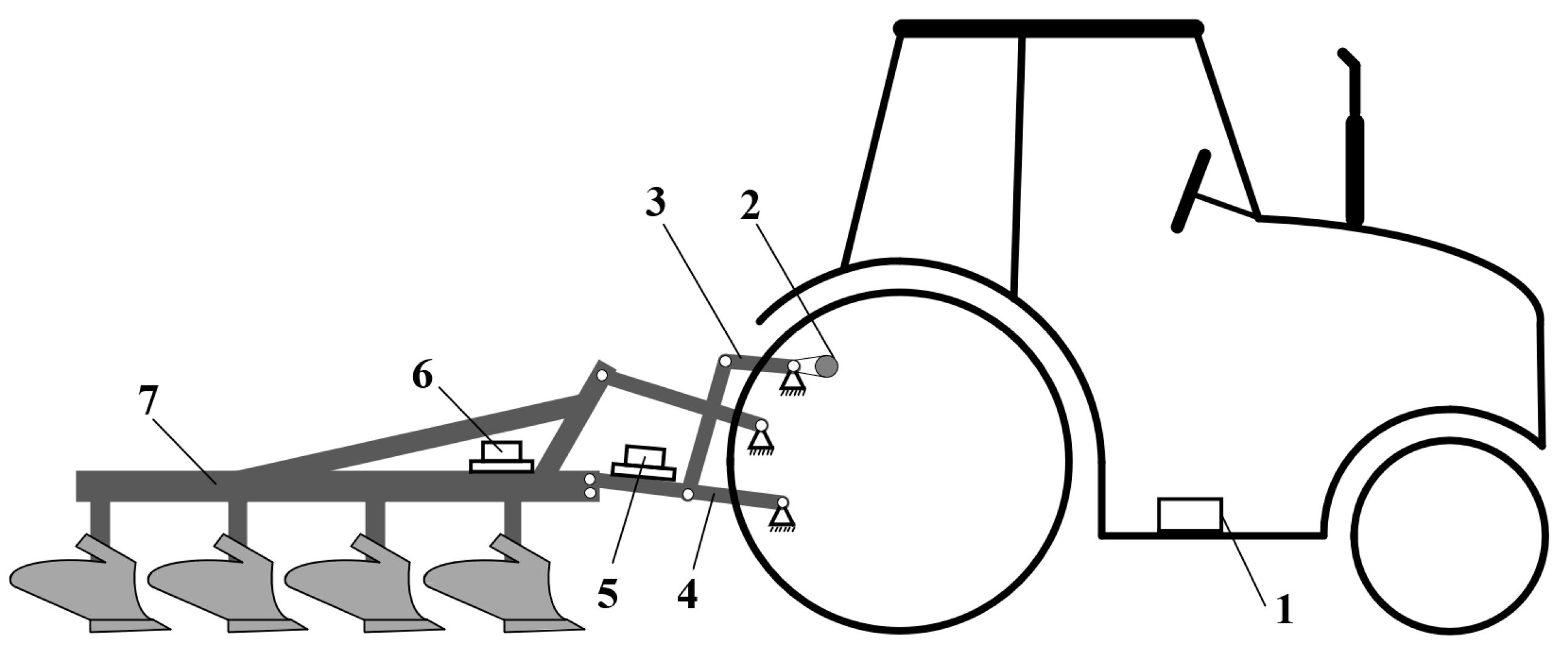
2. Tillage Depth Detection Scheme

As shown in Figure 1, a tractor tillage depth detection method based on attitude anti-disturbance estimation is proposed in this study. The hardware system for tractor tillage depth detection includes two IMUs, a rotary encoder, and a microcontroller. One of the IMUs is laid at the lower link of the tractor suspension system to measure the horizontal attitude of the lower link. The other IMU is placed above the share plow to measure the horizontal attitude of the plow implement. The Y-axis direction of both IMUs points in the forward direction of the tractor. The rotary encoder is mounted and fixed with the lifting arm of the suspension system and is used to measure the rotation angle of the lifting arm. The microcontroller is located in the tractor cab. On the one hand, the microcontroller receives raw data from the two IMUs and solves the horizontal attitude. On the other hand, it receives data from the rotary encoder and performs online calibration of the tillage depth detection model parameters.

2.1. Tillage Depth Detection Model

A tillage depth detection model based on multiple attitudes is built, taking into account the actual tillage operation scenario of tractors. In this model, multiple attitude sensors are deployed to detect horizontal attitudes at different positions and thus achieve real-time measurement of tillage depth. The length of the lever arm and the attitudes at different positions are important parameters that affect the accuracy of tillage depth detection. The geometric length parameters used in the tillage depth detection model need to be measured in advance, mainly including the length of the lower link L S and the longitudinal arm length of the plow L P . The attitude detection of the lower link and the plow uses the algorithm presented in Section 2.2.
The attitude of the plow implement on the horizontal ground needs to be marked in advance before the actual cultivation. When the plow implement is connected with the horizontal ground, the pitch angle of the lower link is indicated as θ S 0 and the pitch angle of the plow is indicated as θ P 0 . The tillage depth of the plow can be adjusted by controlling the lifting and lowering of the suspension system during the plowing process of the tractor. The real-time pitch angle of the lower link is denoted as θ S n , and the real-time pitch angle of the plow is denoted as θ P n . The model for tillage depth detection based on attitude measurement is developed as follows:
H i = L S sin θ S n sin θ S 0 + L P _ y i sin θ P n sin θ P 0
where H i ,   i = 1,2 , 3,4 denotes the tillage depth of the four plow bottoms of the share plow and L P _ y i ,   i = 1,2 , 3,4 denotes the lever-arm length of the four plow bottoms of the share plow. The lateral view of the tractor plowing operation, with the lever-arm length of the share plow, is shown in Figure 2.
Before conducting tillage tests, after the plow is mounted on the tractor, the length of the arms of the tractor’s three-point hitch system is adjusted to ensure that the plow remains as level as possible (close to 0 degrees) at the target tillage depth. This ensures that the tillage depths of the four plowshares are theoretically consistent. In this case, when measuring the initial pitch angle θ P 0 , only the first plowshare contacts the ground theoretically. Therefore, the calculation result of the first plowshare can be used as the final plowing depth.

2.2. Attitude Estimation Method

The definitions of each coordinate system used in this article are provided as follows:
(1)
b-frame: SINS body frame, IMU-centered orthogonal reference frame aligned with Right–Forth–Up (RFU) axes. In this paper, the IMU is placed above the share plow. Therefore, the origin of the b-frame is the IMU, and the directions of the b-frame are rightward, forward, and upward of the tractor–plow, respectively.
(2)
n-frame: navigation frame, equivalent to geographic frame, carrier-centered orthogonal reference frame aligned with East–North–Up (ENU) geodetic axes. In this paper, the origin of the n-frame is the IMU, and the directions of the n-frame are eastward, northward, and upward of the tractor–plow, respectively.
(3)
e-frame: earth frame, Earth-centered Earth-fixed (ECEF) orthogonal reference frame. In this paper, the origin of the e-frame is the geocentric. The x-axis of the e-frame points to the intersection of the tractor–plow’s meridian and the equator. The z-axis points to the North Pole. The y-axis, along with the x-axis and z-axis, forms a right-handed coordinate system.
(4)
b0-frame: inertially non-rotating frame aligned with the b-frame at t0.
(5)
n0-frame: inertially non-rotating frame aligned with the n-frame at t0.
(6)
e0-frame: inertially non-rotating frame aligned with the e-frame at t0.
The body frame of an IMU is denoted as the b-frame, and the geographic frame is selected as the navigation frame and denoted as the n-frame. The attitude matrix C b n t from the b-frame to the n-frame can be decomposed into three sub-matrices as follows:
C b n t = C b t n t = C n 0 n t C b 0 n 0 C b t b 0
where n0-frame is the n-frame at time t0; b0-frame is the b-frame at time t0; C b 0 n 0 is the attitude matrix C b t n t at time t0; C n 0 n t is the attitude matrix of n-frame from time t0 to time t; and C b t b 0 is the attitude matrix of the b-frame from time t to time t0.
The initial values of C n 0 n t and C b t b 0 are both 3-dimensional identity matrices, namely, C n 0 n t 0 = C b t 0 b 0 = I 3 . The differential equations of the directional cosine matrices C n 0 n t and C b t b 0 are expressed as follows:
C ˙ n t n 0 = C n t n 0 ω i n n ×
C ˙ b t b 0 = C b t b 0 ω i b b ×
where C ˙ n t n 0 is the differential form of the attitude matrix C n t n 0 ; C n t n 0 is the transpose matrix of C n 0 n t , namely, C n t n 0 = C n 0 n t T ; C ˙ b t b 0 is the differential form of the attitude matrix C b t b 0 ; ω i n n denotes the projection of the rotational angular velocity of the n-frame with respect to the i-frame under the n-frame; and ω i b b denotes the projection of the rotational angular velocity of the b-frame with respect to the i-frame under the b-frame.
When the tractor is stationary, the linear speed is zero. At this point, the specific force equation of the IMU is expressed as follows:
0 = C b n t f b + g n
where f b is the specific force measured by the accelerometer; g n = 0 0 g T is the gravitational acceleration vector; and g is the local gravitational acceleration value.
Combining Equations (2) and (5) yields
C b t b 0 f b = C n 0 b 0 C n t n 0 g n
where C n 0 b 0 is the transpose matrix of C b 0 n 0 .
The vector observation model based on apparent gravity can be constructed as
f b 0 = C n 0 b 0 g n 0
where f b 0 and g n 0 , respectively, represent the observation vector and reference vector.
The specific calculation equations are as follows:
f b 0 = C b t b 0 f b g n 0 = C n t n 0 g n
The Earth frame is denoted as the e-frame, and the e0-frame is the e-frame at time t0. The observation vector is calculated as follows:
f b 0 = C n 0 b 0 g n 0 = C n 0 b 0 C e 0 n 0 C e e 0 C n e g n
where the attitude matrices C n 0 b 0 , C e 0 n 0 and C n e are all constant matrices. Only the attitude matrix C e e 0 is a time-varying matrix. The attitude matrices C e 0 n 0 and C n e are only related to the longitude and latitude of the tractor. The attitude matrix C e e 0 changes with the rotation of the Earth. The expressions for the attitude matrices C e 0 n 0 , C n e , and C e e 0 are as follows:
C e 0 n 0 = C n e T = sin λ cos λ 0 cos λ sin L sin λ sin L cos L cos λ cos L sin λ cos L sin L
C e e 0 = cos ω i e t sin ω i e t 0 sin ω i e t cos ω i e t 0 0 0 1
where λ represents the longitude of the tractor, L represents the latitude of the tractor, and ω i e represents the rotational velocity of the Earth.
The constant attitude matrix C n 0 b 0 can be represented as C n 0 b 0 = c h j , h = 1,2 , 3 ; j = 1,2 , 3 . Combined with Equations (9)–(11), the observation vector can be further solved as follows:
f b 0 = c 11 c 12 c 13 c 21 c 22 c 23 c 31 c 32 c 33 sin λ cos λ 0 cos λ sin L sin λ sin L cos L cos λ cos L sin λ cos L sin L cos ω i e t sin ω i e t 0 sin ω i e t cos ω i e t 0 0 0 1 sin λ cos λ sin L cos λ cos L cos λ sin λ sin L sin λ cos L 0 cos L sin L 0 0 g = c 11 c 12 c 13 c 21 c 22 c 23 c 31 c 32 c 33 sin λ cos λ 0 cos λ sin L sin λ sin L cos L cos λ cos L sin λ cos L sin L g cos λ cos L g sin λ cos L 0 g cos λ cos L g sin λ cos L 0 0 0 g sin L cos ω i e t sin ω i e t 1 = κ 11 κ 12 κ 13 κ 21 κ 22 κ 23 κ 31 κ 32 κ 33 cos ω i e t sin ω i e t 1 = K cos ω i e t sin ω i e t 1
In practical applications, it is necessary to consider the measurement errors contained in the output data of the IMU, as well as the impact of high-frequency vibrations caused by the tractor’s engine. The outputs of the gyroscope and the accelerometer contain errors and are denoted as ω ~ i b b and f ~ b , respectively. The observation vectors containing measurement errors are represented as follows:
f ~ b 0 = K cos ω i e t sin ω i e t 1 + C ~ b t b 0 b + w a b ϕ ~ b 0 × C ~ b t b 0 f ~ b + C ~ b t b 0 a b
where C ~ b t b 0 represents the attitude matrix updated by ω ~ i b b , b represents the bias vector of the accelerometer, w a b represents the measurement noise vector of the accelerometer, ϕ ~ b 0 represents the misalignment angle between C ~ b t b 0 and C b t b 0 , and a b represents the interference acceleration caused by tractor vibration.
The vector observation model in Equation (13) only utilizes the vector information at the current moment, and all previous vector information is discarded. To reduce the influence of random error terms and fully utilize all vector information in the attitude solving process, a vector observation model based on apparent velocity is derived and constructed by integrating vector information on both sides of Equation (13):
C ~ b t b 0 f ~ b d t = S cos ω i e t sin ω i e t t 1 + δ v
where δ v represents the measurement noise of the apparent velocity vector. Equation (14) provides the relationship between the true apparent velocity vector and time. By taking matrix K as the state variable, Equation (14) can be utilized as the observation equation to calculate the reconstructed apparent velocity vector.
In the parameter identification model, it is assumed that all three channels of the apparent gravity vector are uncoupled. Therefore, the three channels are represented by a unified parameter identification model as follows:
Χ p , M = Χ p , M 1 β ~ p , M = H t M Χ p , M + δ β p , M
where M represents the discrete time, namely, t M = Μ · Δ t , where Δ t represents the sample interval of the IMU. Χ p , M represents the state vector at time t M . H t M represents the measurement update matrix at time t M . The term p = x , y , z represents the three channels of the vector. The term β ~ p , M represents the measurement information of channel p, namely β ~ p , M = f ~ p , M b 0 . The term δ β p , M represents the measurement noise of channel p.
The observation vector β ~ M obtained at time t M can be expressed as the sum of the trigonometric and power functions, which can be decomposed into a power series. A polynomial fitting model is established as follows:
β ~ p , M = k = 0 n a p , k x k + δ β ~ p , M = a p , 0 + a p , 1 x + a p , 2 x 2 + + a p , u x u + δ β ~ p , M
where p = x , y , z represents the three channels of the observation vector, a p , l , l = 0,1 , 2 , , u , indicates the parameters to be estimated, x l , l = 0,1 , 2 , , u represent the dependent variable of the fitted model, and δ β ~ p , M is the residual fitting error of the observation vector of channel p.
The real observation vector can be expressed as a polynomial function of time. If the sampling time is set as the dependent variable Δ t , the Equation (16) can be rewritten as follows:
β ~ p , M = a p , 0 + a p , 1 Δ t + a p , 2 Δ t 2 + + a p , u Δ t u + δ β ~ p , M = H M X p , M + V p , M
where V p , M represents the measurement noise vector, namely, V p , M = δ β ~ p , M . H M represents the measurement update matrix at time t M . H M and X p , M are, respectively,
H M = 1 Δ t Δ t 2 Δ t u
X p , M = a p , 0 a p , 1 a p , 2 a p , u T
It is assumed that after polynomial fitting, only the random error remains in the channel p of the observation vector. Then, V p , M follows a zero-mean Gaussian distribution, i.e., E V p , M = 0 , E V p , M V p , M T = R M . Based on the model given in Equation (17), the recursive least squares method is used to estimate the state vector X p , M . The specific estimation process is as follows:
K M = P M 1 H M T H M P M 1 H M T + R M 1
X ^ p , M = X ^ p , M 1 + K M β ~ p , M H M X ^ p , M 1
P M = I K M H M P M 1
where K M represents the filter gain matrix at time t M , P M 1 represents the mean square error matrix of state estimation error at time t M , R M represents the covariance matrix of the measurement noise at time t M , X ^ p , M represents the state estimation vector at time t M , and X ^ p , M 1 represents the one-step prediction vector of the state at time t M .
After estimating the state vector using the recursive least squares algorithm, the fitted apparent gravity vector can be recalculated using the estimated parameters:
β ^ p , M = H M Χ ^ p , M
where β ^ p , M represents the fitted observation vector. Then, a new vector observation model can be represented as follows:
β ^ M = C n 0 b 0 α M + δ β M
where β ^ M represents the observation vector after reconstruction at time t M ,and δ β M represents the remaining error after fitting the observation vector. The reference vector is represented as follows:
α M = 0 t C n t n 0 g n d t = k = 0 M 1 t k t k + 1 C n t n 0 g n d t = k = 0 M 1 C n t k n 0 t I 3 + t 2 2 ω i n n × g n
where C n t k n 0 represents the attitude matrix of the n-frame from time t k to time t 0 .
The vector observation model is represented in quaternion form:
β M = q n 0 b 0 α M q n 0 b 0 *
where β M represents the observation vector after ignoring the remaining error, q n 0 b 0 represents the quaternion corresponding to the attitude matrix C n 0 b 0 , represents the multiplication operation of two quaternions, and · * represents the conjugate quaternion.
Multiplying quaternion q n 0 b 0 on both sides of the equation constructs two matrices as follows:
M α = 0 α M T α M α M ×
M β = 0 β M T β M β M ×
where M α represents the matrix corresponding to the reference vector α M , and M β represents the matrix corresponding to the observation vector β M .
The measurement model in Equation (26) can be rephrased as:
M β M α q n 0 b 0 = 0
Using the constraint idea of least squares, the following cost function is obtained from Equation (26):
L q n 0 b 0 = min q n 0 b 0 0 t M β M α q n 0 b 0 2 d t = min q n 0 b 0 q n 0 b 0 T 0 t M β M α T M β M α d t q n 0 b 0
K = 0 t M β M α T M β M α d t
The quaternion q n 0 b 0 that satisfies the minimum cost function L q n 0 b 0 is the eigenvector corresponding to the minimum eigenvalue λ m i n of the matrix K .

2.3. The Calibration Model

The high-precision horizontal attitude estimation of a tractor in a stationary state can be achieved as shown in Section 2.2. However, in the actual cultivation process of farmland operation, the horizontal attitude of the plow and the lower link fluctuates greatly, while the detection of the dynamic rotation angle of the lifting arm is good. Therefore, an online calibration model for the rotation angle of the lifting arm and the horizontal attitude of the plow is established using the rotary encoder and IMU to achieve dynamic real-time estimation of the horizontal attitude of the plow and lower link.
The calibration model for the rotation angle of the lifting arm and the pitch angle of the lower link is established and shown in Equation (32). The calibration model for the rotation angle of the lifting arm and the pitch angle of the plow is established and shown in Equation (33).
θ S = a 1 α S 2 + b 1 α S + c 1 = H X 1
θ P = a 2 α S 2 + b 2 α S + c 2 = H X 2
where a 1 b 1 c 1 and a 2 b 2 c 2 are the calibration parameters to be estimated. The term α S represents the rotation angle of the lifting arm measured by the rotary encoder. Vector H = α S 2 α S 1 is the observation vector. X 1 = a 1 b 1 c 1 T and X 2 = a 2 b 2 c 2 T are the parameter vectors to be estimated.
The adaptive Kalman filter method is utilized to estimate the calibration parameters X i , where i = 1,2 . Taking the parameter vector X 1 as an example, the specific estimation process is as follows:
e d = θ ^ S H d X 1 , d 1
R d = R d 1 + 1 d e d e d T R d 1
K d = P d 1 H d T H d P d 1 H d T + R d 1
X 1 , d = X 1 , d 1 + K d e d
P d = P d 1 K d H d P d 1 H d T + R d K d T
where d represents the sample time t d of the rotary encoder and IMU, e d represents the innovation vector at the time t d , X 1 , d 1 represents the one-step predicted state vector at the time t d , R d represents the error covariance matrix of the measurement noise of the lower link’s pitch angle at the time t d , H d represents the measurement matrix at the time t d , K d represents the filtering gain at the time t d , P d 1 represents the mean square error of the state estimation at the time t d , and X 1 , d represents the state vector at the time t d .
After identifying the fitting parameters X i , where i = 1,2 , using the adaptive Kalman filter algorithm, the fitted pitch angles of the lower link θ ^ S and the plow θ ^ P are recalculated using the identified parameters as follows:
θ ^ S = a 1 α S 2 + b 1 α S + c 1 = H X 1
θ ^ P = a 2 α S 2 + b 2 α S + c 2 = H X 2
During the parameter calibration process, the plow is first raised to the highest position, and the lifting arm is controlled to slowly lower the plow to the lowest position. The microcontroller continuously records the raw data sent by the rotary encoder and the two IMUs and calculates the parameter identification results in real time.

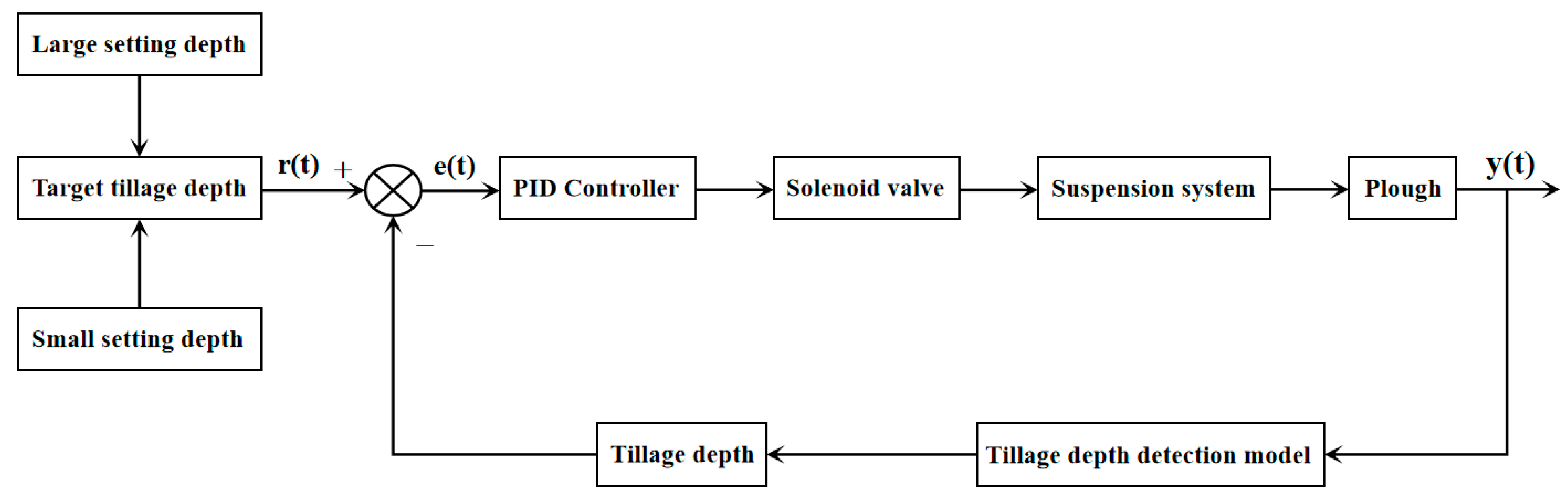
3. Tillage Depth Control Scheme

An autonomous tractor plowing operation can not only improve the efficiency of cultivation and guarantee its quality, but also facilitate the popularization and application of unmanned tractor autonomous operation technology. This section focuses on the calibration method for the parameters of the tillage depth detection model and the algorithm of tillage depth control. Finally, the complete process of autonomous control of tractor tillage depth is summarized.

3.1. The PID Control Algorithm

After measuring real-time plowing depth results, the use of electronically controlled hydraulic valves can accomplish online regulation and control of the tillage depth. To avoid the frequent adjustment of the controller caused by tillage depth detection errors and random interferences, a control strategy combining the interval target value and PID algorithm is adopted. The PID control algorithm is a kind of feedback control strategy that regulates the output of the system through the linear combination of proportional, integral, and differential control methods to realize the precise control of the set value. Using the PID control algorithm, the response speed of the control system can be improved by adjusting the proportional parameter. The steady error of the control system can be eliminated by adjusting the integral parameter. The dynamic performance of the control system can be ameliorated by adjusting the differential parameter. The structure of the PID controller is shown in Figure 3.
In Figure 3, r t is the system input target value, e t e(t) is the system deviation, u t is the control output, and y t is the actual output value.
The control output expression of the PID control algorithm is as follows:
u t = K P e t + 1 T I 0 t e t d t + T D d e t d t
where K P denotes the proportional gain, T I denotes the integral time constant, and T D denotes the differential time constant.
A schematic diagram of the tillage depth control algorithm is shown in Figure 4. First, the target tillage depth interval value is input to the controller. Then, the controller calculates the error between the actual measured tillage depth and the target tillage depth, as well as the corresponding control output according to the PID control algorithm. Finally, the controller controls the tractor suspension system through the solenoid valve to drive the plow to reach the target plowing depth. At the same time, the tillage depth detection system measures the actual tillage depth and provides the information back to the controller to form a closed-loop control.

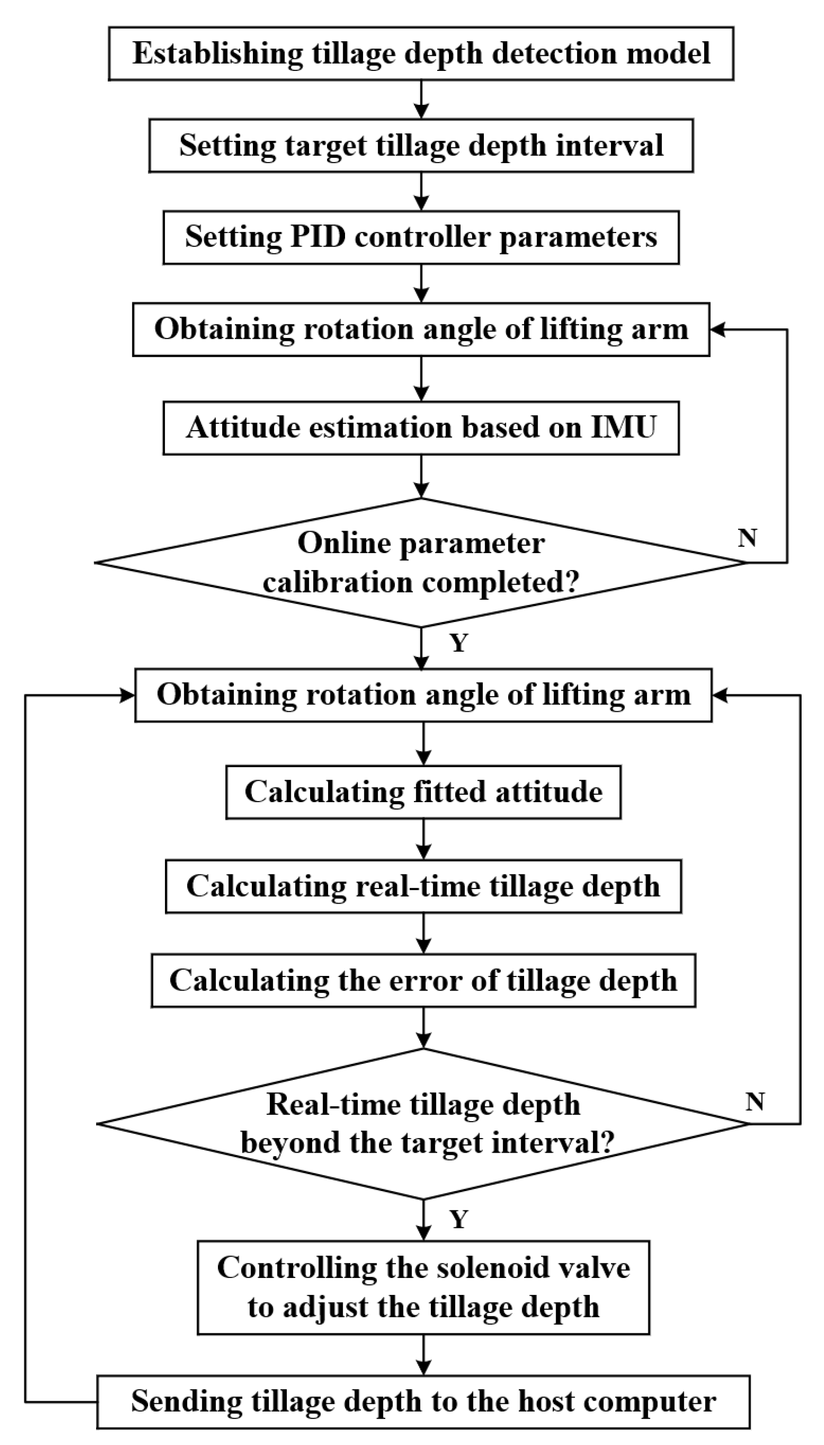
3.2. The Tillage Depth Control Process

The complete process of the proposed real-time detection and automatic control system for tractor tillage depth is shown in Figure 5. The whole process can be divided into four parts as follows:
(1)
Initialization: The tractor tillage depth detection model is first established. Then the target tillage depth interval during the plowing operation and the parameters of the PID controller are set.
(2)
Parameter calibration: The model parameters between the rotation angle of the lifting arm and the pitch angle of the plow implement are calibrated. First, the rotation angle of the lifting arm is obtained. Second, the attitude estimation method proposed in Section 2.2 is used to solve the horizontal attitude of the lower link and the plow implement. Finally, the model parameters are estimated online using the adaptive Kalman filter algorithm.
(3)
Tillage depth detection: The real-time tillage depth detection during the tractor plowing operation is achieved. The fitted pitch angles of the lower link and the plow implement are calculated using the rotation angle of the lifting arm and the calibration model. The real-time tillage depth is solved by substituting the fitted pitch angle into the tillage depth detection model.
(4)
Tillage depth control: The autonomous control of the tillage depth during the tractor plowing operation is completed. The tillage depth error is calculated using the real-time tillage depth detection results. The PID controller outputs the control parameters to the solenoid valve according to the tillage depth error. By controlling the tractor suspension system to drive the plow, the tillage depth control system accomplishes the autonomous regulation and control of tillage depth.

4. Simulation and Field Tests

This section describes the simulation and field tests of the tillage depth detection and regulation methods in Section 2 and Section 3 to validate the effectiveness of the proposed methods.

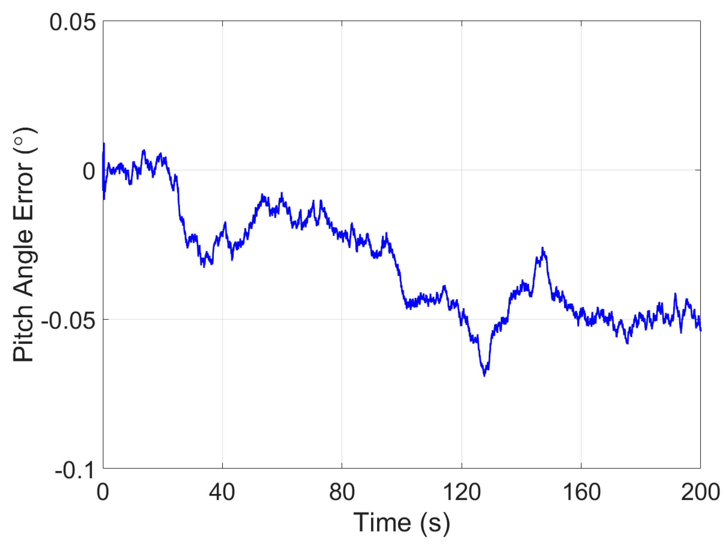
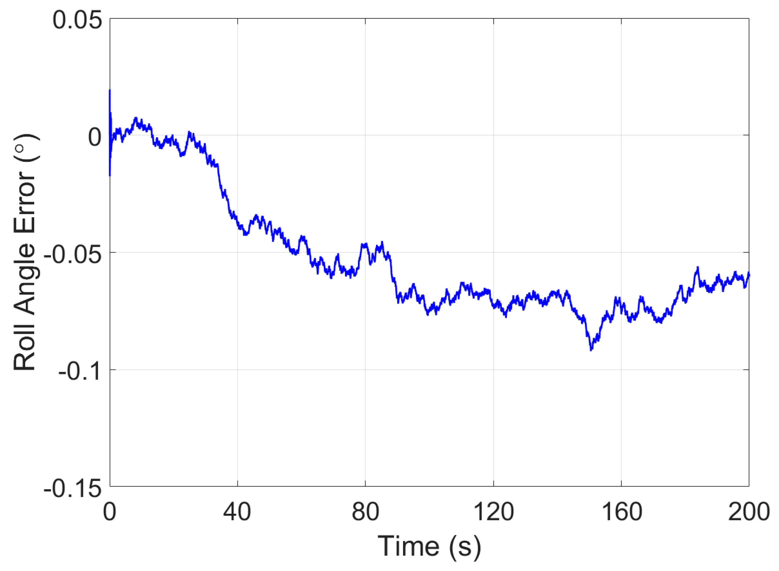
4.1. Simulation Test of Attitude Estimation

A simulation test was conducted to verify the effectiveness of the proposed attitude estimation method for the plow implement in Section 2.2. The parameters of the IMU in the simulation test were set as described in Table 1.
During the attitude estimation simulation test on a stationary base, the real attitude was set as follows: pitch angle of −1°, roll angle of 2°, yaw angle of −3°. The initial attitude of the attitude estimation in the simulation was set as follows: pitch angle of 0°, roll angle of 0°, yaw angle of 0°. The simulation test lasted for 200 s.
Figure 6 and Figure 7 present the horizontal attitude error plots of the proposed attitude estimation method under stationary conditions. For low-cost IMUs, a large device error seriously affects the accuracy of attitude estimation. In this study, the observation vector based on apparent velocity was used to effectively eliminate the effect of random white noise through integration. Meanwhile, vector reconstruction further reduced the effect of device error on the observation vector during attitude estimation. As shown in the figures, the attitude estimation method can achieve stable convergence of the horizontal angle attitude error within 0.1°. Therefore, the method provides a good basis for accomplishing horizontal attitude estimation under tractor vibration.

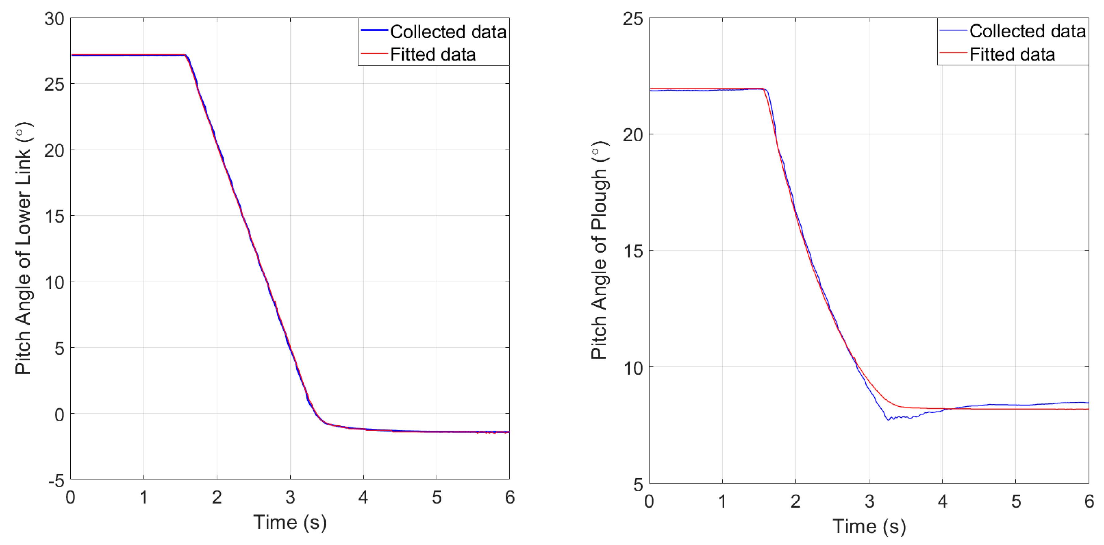
4.2. Online Calibration Test of Model Parameters

A parameter calibration method based on an adaptive Kalman filter was developed for the online calibration of model parameters between the rotation angle of the lifting arm and the pitch angle of the plow and the lower link. The specific steps are as follows:
(1)
The plow implement is lifted to the highest place by the tractor suspension system. Pressing and holding the “Calibration” button on the microcontroller panel for more than 5S is utilized as the opening signal for initiating the calibration process. The microcontroller uses the received data to start the parameter identification process of the calibration model, including the rotation angle of the lifting arm and the horizontal attitude of the lower link and the plow.
(2)
The plow implement is lowered slowly by the tractor suspension system. The microcontroller records in real time the rotation angle of the lifting arm, as well as the horizontal attitude of the lower link and the plow and continues the parameter identification.
(3)
The plow implement is lowered to the lowest position by the tractor suspension system. Pressing and holding the “Calibration” button on the microcontroller panel for more than 5S is utilized as the end signal of the calibration process. The microcontroller stops the parameter identification process and saves the results.
(4)
The microcontroller starts to use the calibration parameters and the rotation angle of the lifting arm to calculate the pitch angle of the lower link and the plow when the tractor is plowing. Finally, the dynamic measurement of tillage depth can be completed according to the tillage depth detection model.
The results of the data fitting process are shown in Figure 8.
The fitted model between the rotation angle of the lifting arm and the pitch angle of the lower link is expressed as follows:
θ ^ S = 0.001 α S 2 0.6671 α S + 34.9362
where θ ^ S is the fitted pitch angle of the lower link and α S is the rotation angle of the lifting arm. The curve of the fitted results is shown on the left side of Figure 8.
The fitted model between the rotation angle of the lifting arm and the pitch angle of the plow is expressed as follows:
θ ^ P = 0.0069 α S 2 0.782 α S + 29.9627
where θ ^ P is the fitted pitch angle of the lower link and α S is the rotation angle of the lifting arm. The curve of the fitted result is shown on the right side of Figure 8.

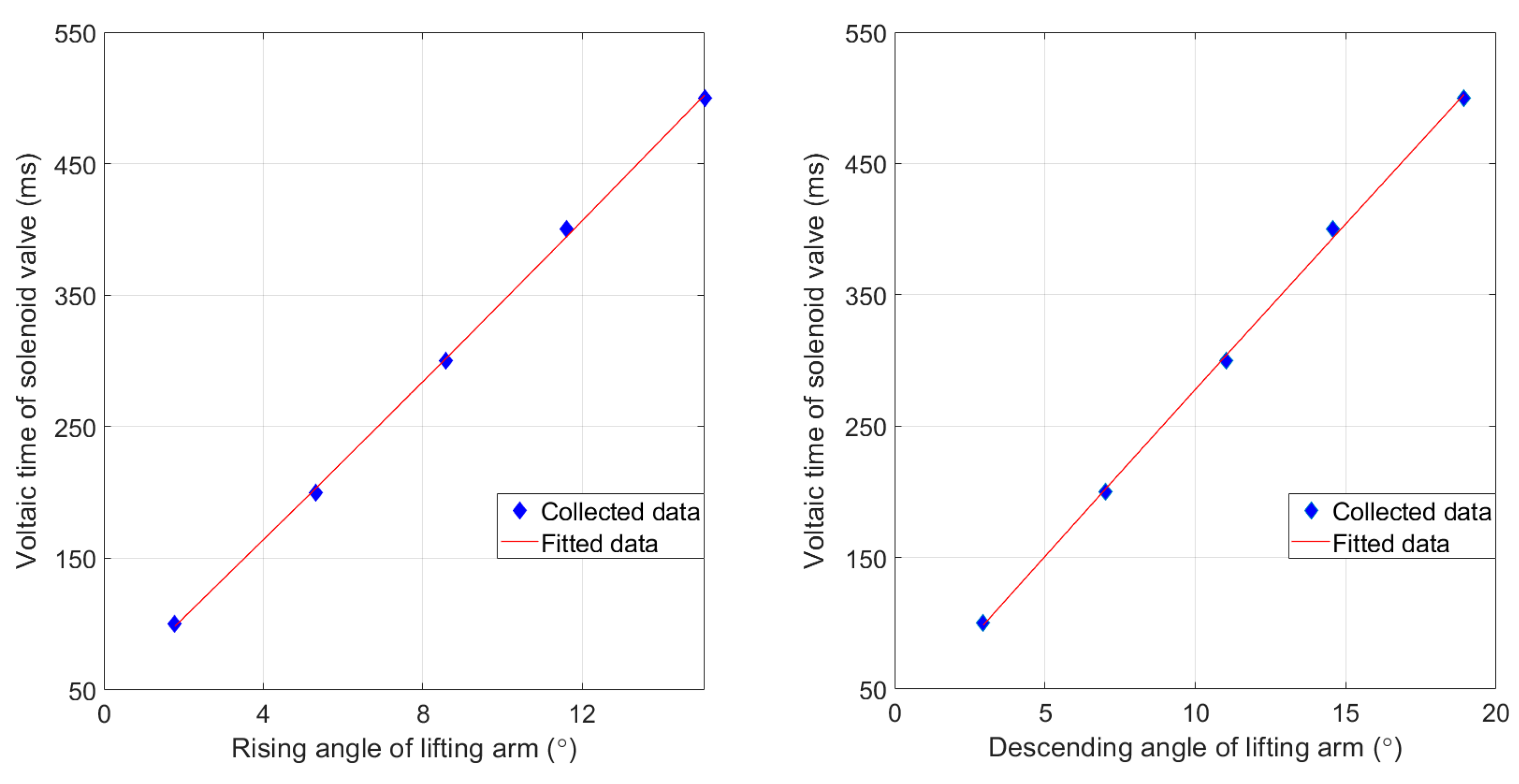
4.3. Parameter Test of Solenoid Valve
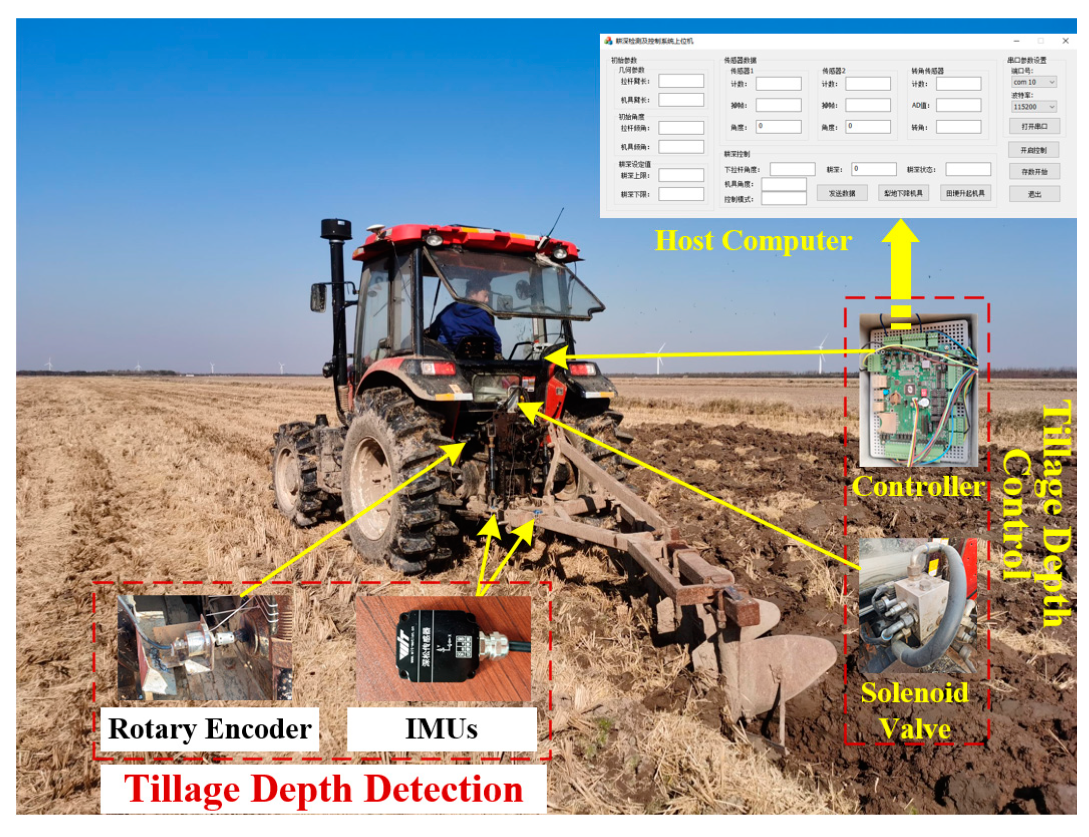
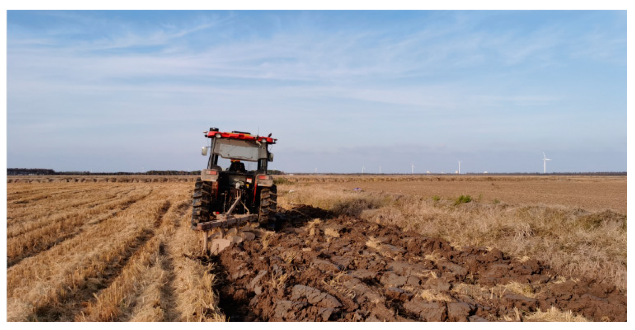
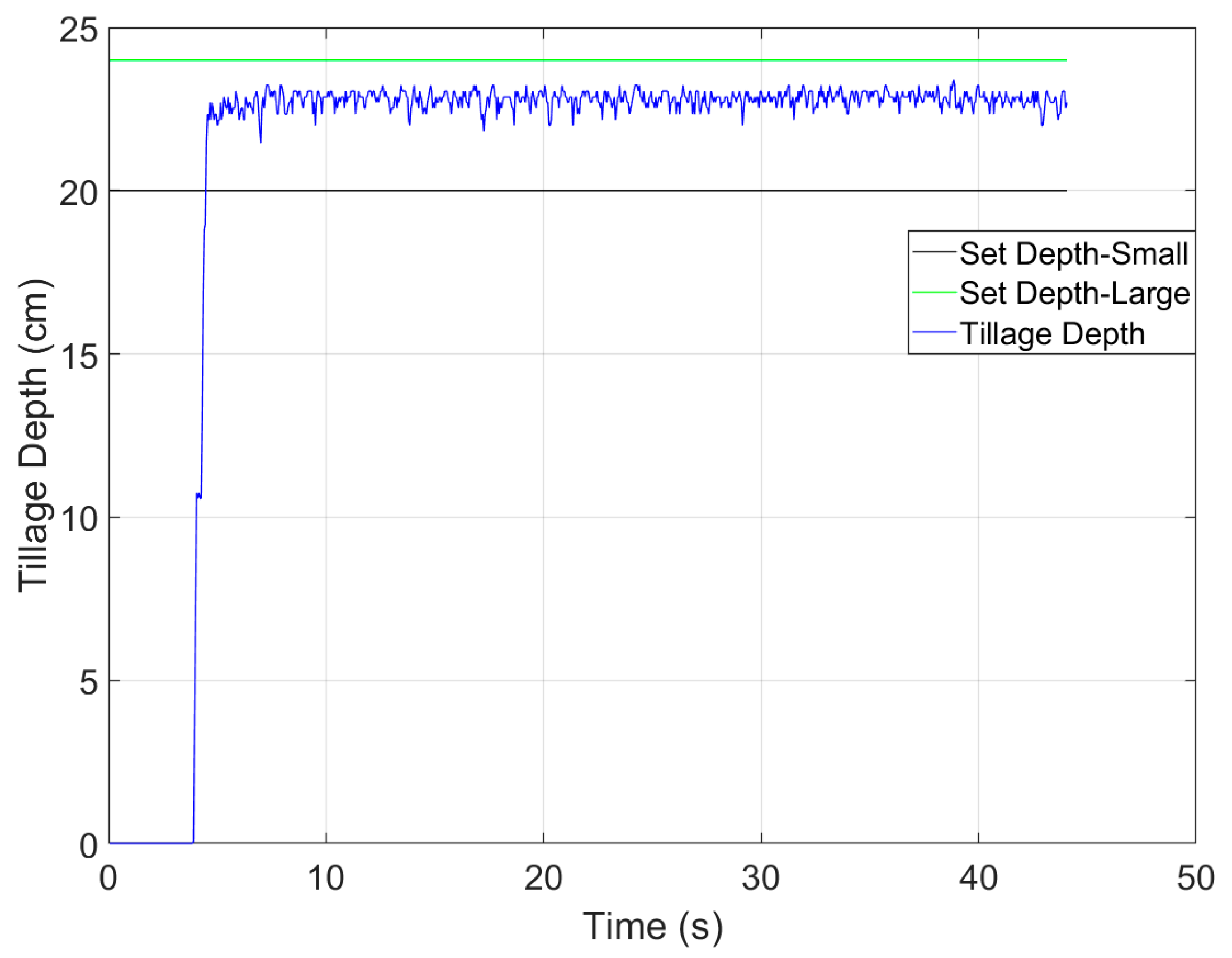
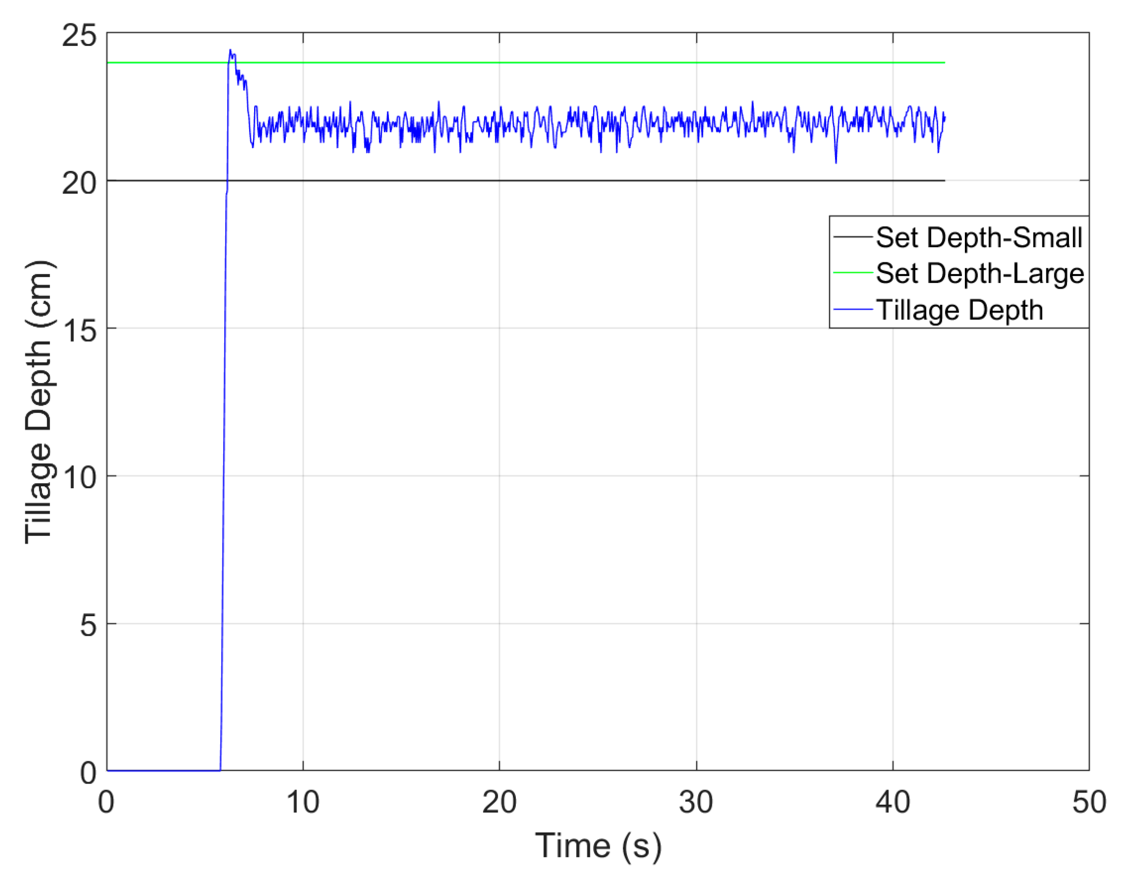
An electronically controlled hydraulic valve was used to control the tractor suspension system in this study so as to achieve real-time control of the tillage depth of the plow. The rotation angle of the lifting arm can be adjusted by controlling the make break time of the electronically controlled hydraulic valve. Therefore, before carrying out tillage depth control, it is necessary to obtain the relationship model between the rotation angle of the lifting arm and the make break time of the hydraulic valve, which provides an a priori reference for the parameter setting of the PID controller.
The specific calibration process is as follows: First, a number of different solenoid valve make break timepoints are selected. The rotation angle of the lifting arm at each make break time of the hydraulic valve is recorded. The experiment is carried out more than five times for each make break time of the solenoid valve. The mean value of the rotation angle of the lifting arm is calculated. The mathematical model parameters between the make break time of the solenoid valve and the rotation angle of the lifting arm are fitted using MATLAB software (https://www.mathworks.com/products/matlab.html, accessed on 10 May 2024).
The testing results of the solenoid valve parameter are shown in Figure 9.
The fitted model between the rotation angle of the lifting arm and the make break time of the solenoid valve when lifting the plow implement is expressed as
t ^ = 0.079 θ u p 2 + 29.0705 θ u p + 46.2455
where   t ^ is the fitted make break time of the solenoid valve and θ u p is the rotation angle of the lifting arm when lifting the plow implement. The curve of the fitted results is shown on the left side of Figure 9.
The fitted model between the rotation angle of the lifting arm and the make break time of the solenoid valve when lowering the plow implement is expressed as
t ^ = 0.0163 θ d o w n 2 + 25.6413 θ d o w n + 22.9972
where t ^ is the fitted make break time of the solenoid valve and θ d o w n is the rotation angle of the lifting arm when lowering the plow implement. The curve of the fitted results is shown on the right side of Figure 9.

4.4. Field Test

The structure of the tractor tillage depth real-time detection and autonomous control system developed in this study is shown in Figure 10. The tractor tillage depth detection and control system uses a STM32 microcontroller as the control terminal. The real-time tractor tillage depth is calculated by measuring the rotation angle of the lifting arm using the rotary encoder, along with the pitch angle of the lower link and the plow using the IMU. The autonomous control of tillage depth can be achieved through the electronically controlled hydraulic valve to control the tractor suspension mechanism, which adjusts the tillage depth by lifting or lowering the plow implement. Among the components, the host computer of the tillage depth autonomous control system completes the control command issuance and data display. The microcontroller completes the tasks of data acquisition, plowing depth calculation, control output, and data transmission. The parameters of the IMU and rotary encoder used in the field test are as shown in Table 2.
Field tests of the tractor plowing operation were carried out on Shangshi Farm, Chongming District, Shanghai to verify the effectiveness of the proposed tillage depth detection and control system in an actual farming environment. The experimental site for the field tests is shown in Figure 11. The rice stubble in the experimental plot is between 20 and 30 cm in height. This results in signal attenuation for the distance-based tillage depth detection method. And the wheel of the feeler wheels-based tillage depth detection method is unable to make full contact with the ground. Due to these factors, both methods are unable to effectively measure the tillage depth. Given the limitations of the actual environment and experimental conditions, a comprehensive comparative test of the tillage depth detection methods was not conducted in the field test. However, Manual measurements were performed using a tillage depth gauge, and the average measurement error was within 0.8 cm. The manual measurement results show that the tillage depth detection scheme proposed in this study has good accuracy.
During the tractor plowing operation, the velocity of the tractor was up to 10 km/h. The target interval of the tillage depth was set at 20~24 cm. The results of the field tests are shown in Figure 12 and Figure 13. To present clearer and more specific statistics regarding the performance of the tillage depth detection and control system in the field tests, Table 3 lists the error statistics of tillage depth control. In Table 3, MN denotes the mean of the tillage depth control error, STD denotes the standard deviation, and RMS denotes the root mean square.
The following conclusions can be drawn from the curve and error statistics of tillage depth control: ① The tillage depth detection and control system can accomplish the real-time acquisition of tillage depth at a high frequency. ② The tillage depth can be stably controlled within the set target interval during the tractor plowing operation. ③ When the tillage depth exceeded the set target interval during the field tests, the controller quickly and stably regulated it back to the target interval. ④ During the field tests, the tillage depth control error of the tractor was less than 1 cm (RMS).

5. Conclusions

In this study, a tillage depth detection and control system for tractor plowing was proposed to achieve precise real-time detection and stable autonomous control of the tillage depth. A tillage depth detection model based on the attitude measurement of the plow was established. Dynamic detection of the tillage depth during tractor plowing operations can be attained through the online calibration of parameters. A PID controller is used to adjust the lifting or lowering of the plow implement by controlling the solenoid valve, thus achieving stable control of the tillage depth. Simulation and field tests were conducted to verify the performance of the proposed method. The experimental results show that the tillage depth can be stably controlled within the set target interval during the tractor plowing operation, and the tillage depth control error is less than 1 cm.

Author Contributions

Conceptualization, Y.Z. and B.C.; methodology, Y.Z. and X.W.; software, Z.Y.; validation, Y.Z., Y.G. and X.W.; formal analysis, Y.Z. and B.C.; investigation, X.W.; data curation, Y.Z. and Z.Y.; writing—original draft preparation, Y.Z. and B.C.; writing—review and editing, Y.Z. and X.W.; funding acquisition, B.C. and X.W. All authors have read and agreed to the published version of the manuscript.

Funding

This work was partially funded by the Natural Science Foundation of China under grant no. 32401719, the Natural Science Foundation of Jiangsu Province under grant no. BK20240877, the Jiangsu Province and Education Ministry Co-Sponsored Synergistic Innovation Center of Modern Agricultural Equipment under grant no. XTCX2009, the Natural Science Foundation of China under grant no. 32271999, the Priority Academic Program Development of Jiangsu Higher Education Institutions under grant no. PAPD-2023-87, the Open Funding from the Key Laboratory of Modern Agricultural Equipment and Technology (Jiangsu University), Ministry of Education, under grant no. MAET202301, and the National Science and Technology Major Project (Grant 361 No. 2022ZD0115804).

Institutional Review Board Statement

Not applicable.

Data Availability Statement

The data presented in this study are available on request from the corresponding author. The data are not publicly available due to the privacy of the subjects involved in the study.

Conflicts of Interest

The authors declare no conflicts of interest.

References

  1. Singh, N.K.; Dogra, B.; Manes, G.S.; Parihar, D.S.; Salem, A.; Elbeltagi, A. Effect of the Spading Machine on Various Soil Parameters at Different Tillage Depths. Sustainability 2024, 16, 4334. [Google Scholar] [CrossRef]
  2. Yu, Y.; Hao, S.H.; Guo, S.B.; Tang, Z.; Chen, S.R. Motor Torque Distribution Strategy for Different Tillage Modes of Agricultural Electric Tractors. Agriculture 2022, 12, 1373. [Google Scholar] [CrossRef]
  3. Morugán-Coronado, A.; Linares, C.; Gómez-López, M.D.; Faz, A.; Zornoza, R. The impact of intercropping, tillage and fertilizer type on soil and crop yield in fruit orchards under Mediterranean conditions: A meta-analysis of field studies. Agric. Syst. 2020, 178, 102736. [Google Scholar] [CrossRef]
  4. Guo, Y.; Cui, M.L.; Xu, Z.G. Spatial characteristics of transfer plots and conservation tillage technology adoption: Evidence from a survey of four provinces in China. Agriculture 2023, 13, 1601. [Google Scholar] [CrossRef]
  5. Gao, Y.Y.; Yang, Y.F.; Fu, S.; Feng, K.Y.; Han, X.; Hu, Y.Y.; Zhu, Q.Z.; Wei, X.H. Analysis of vibration characteristics of tractor–rotary cultivator combination based on time domain and frequency domain. Agriculture 2024, 14, 1139. [Google Scholar] [CrossRef]
  6. Chen, X.X.; Xu, G.M.; Zhang, X.Y.; Tan, W.C.; Ding, Q.S.; Tagar, A.A. Performance Evaluation of Biomimetic-Designed Rotary Blades for Straw Incorporation in an Intensive Tillage System. Agriculture 2024, 14, 1426. [Google Scholar] [CrossRef]
  7. Hu, R.W.; Liu, Y.J.; Chen, T.; Zheng, Z.Y.; Peng, G.J.; Zou, Y.D.; Tang, C.G.; Shan, X.H.; Zhou, Q.M.; Li, J. Responses of soil aggregates, organic carbon, and crop yield to short-term intermittent deep tillage in Southern China. J. Clean. Prod. 2021, 298, 126767. [Google Scholar] [CrossRef]
  8. Schneider, F.; Don, A.; Hennings, I.; Schmittmann, O.; Seidel, S.J. The effect of deep tillage on crop yield–What do we really know? Soil Tillage Res. 2017, 174, 193–204. [Google Scholar] [CrossRef]
  9. Han, J.Y.; Yan, X.X.; Tang, H. Method of controlling tillage depth for agricultural tractors considering engine load characteristics. Biosyst. Eng. 2023, 227, 95–106. [Google Scholar] [CrossRef]
  10. Huang, S.S.; Ul Islam, M.; Jiang, F.H. The effect of deep-tillage depths on crop yield: A global meta-analysis. Plant Soil Environ. 2023, 69, 105–117. [Google Scholar] [CrossRef]
  11. Pang, J.; Zhang, X.W.; Lin, X.J.; Liu, J.H.; Du, X.W.; Han, J.A. Tillage-Depth Verification Based on Machine Learning Algorithms. Agriculture 2023, 13, 130. [Google Scholar] [CrossRef]
  12. Sun, X.X.; Song, Y.; Wang, Y.F.; Qian, J.; Lu, Z.X.; Wang, T. Design and test of a tractor electro-hydraulic-suspension tillage-depth and loading-control system test bench. Agriculture 2023, 13, 1884. [Google Scholar] [CrossRef]
  13. Luo, C.H.; Wen, C.K.; Meng, Z.J.; Liu, H.Y.; Li, G.Q.; Fu, W.Q.; Zhao, C.J. Research on the slip rate control of a power shift tractor based on wheel speed and tillage depth adjustment. Agronomy 2023, 13, 281. [Google Scholar] [CrossRef]
  14. Kim, Y.S.; Kim, T.J.; Kim, Y.J.; Lee, S.D.; Park, S.U.; Kim, W.S. Development of a real-time tillage depth measurement system for agricultural tractors: Application to the effect analysis of tillage depth on draft force during plow tillage. Sensors 2020, 20, 912. [Google Scholar] [CrossRef] [PubMed]
  15. Hu, K.; Zhang, W.Y.; Qi, B.; Ji, Y. Tillage depth dynamic monitoring and precise control system. Meas. Control-UK 2024. [Google Scholar] [CrossRef]
  16. Jia, H.L.; Guo, M.Z.; Yu, H.B.; Li, Y.; Feng, X.Z.; Zhao, J.L.; Qi, J.T. An adaptable tillage depth monitoring system for tillage machine. Biosyst. Eng. 2016, 151, 187–199. [Google Scholar] [CrossRef]
  17. Jiang, X.H.; Tong, J.; Ma, Y.H.; Li, J.G.; Wu, B.G.; Sun, J.Y. Study of tillage depth detecting device based on Kalman filter and fusion algorithm. Trans. Chin. Soc. Agric. Mach. 2020, 51, 53–60. [Google Scholar]
  18. Lou, S.Y.; He, J.; Lu, C.Y.; Liu, P.; Li, H.; Zhang, Z.G. A tillage depth monitoring and control system for the independent adjustment of each subsoiling shovel. Actuators 2021, 10, 250. [Google Scholar] [CrossRef]
  19. Kim, Y.S.; Siddique, M.A.; Kim, W.S.; Kim, Y.J.; Lee, S.D.; Lee, D.K.; Hwang, S.J.; Nam, J.S.; Park, S.U.; Lim, R.G. DEM simulation for draft force prediction of moldboard plow according to the tillage depth in cohesive soil. Comput. Electron. Agric. 2021, 189, 106368. [Google Scholar] [CrossRef]
  20. Kim, Y.S.; Kim, W.S.; Siddique, M.A.; Baek, S.Y.; Baek, S.M.; Cheon, S.H.; Lee, S.D.; Lee, K.H.; Hong, D.H.; Park, S.U.; et al. Power transmission efficiency analysis of 42 kW power agricultural tractor according to tillage depth during moldboard plowing. Agronomy 2020, 10, 1263. [Google Scholar] [CrossRef]
  21. Wang, A.Z.; Ji, X.; Zhu, Y.Y.; Wang, Q.Z.; Wei, X.H.; Zhang, S.C. Tillage depth regulation system via depth measurement feedback and composite sliding mode control: A field comparison validation study. Meas. Control-UK 2024, 57, 685–702. [Google Scholar] [CrossRef]
  22. Zhou, M.K.; Xia, J.F.; Zhang, S.; Hu, M.J.; Liu, Z.Y.; Liu, G.Y.; Luo, C.M. Development of a depth control system based on variable-gain single-neuron PID for rotary burying of stubbles. Agriculture 2021, 12, 30. [Google Scholar] [CrossRef]
  23. Wang, Y.X.; Jing, H.R.; Zhang, D.X.; Cui, T.; Zhong, X.J.; Yang, L. Development and performance evaluation of an electric-hydraulic control system for subsoiler with flexible tines. Comput. Electron. Agric. 2018, 151, 249–257. [Google Scholar] [CrossRef]
  24. Candan, B.; Soken, H.E. Robust attitude estimation using IMU-only measurements. IEEE Trans. Instrum. Meas. 2021, 70, 9512309. [Google Scholar] [CrossRef]
  25. Zhou, Z.H.; Zeng, C.W.; Tian, X.R.; Zeng, Q.X.; Yao, R. A Discrete Quaternion Particle Filter Based on Deterministic Sampling for IMU Attitude Estimation. IEEE Sens. J. 2021, 21, 23266–23277. [Google Scholar] [CrossRef]
  26. Huang, P.K.; Zhang, Z.G.; Luo, X.W.; Liu, Z.P.; Wang, H.; Yue, B.B.; Gao, W.W. Development of external acceleration identification and attitude estimation system of field working vehicle. Trans. Chin. Soc. Agric. Eng. 2019, 35, 9–15. [Google Scholar]
  27. Vieira, D.; Orjuela, R.; Spisser, M.; Basset, M. Positioning and attitude determination for precision agriculture robots based on IMU and two RTK GPSs sensor fusion. In Proceedings of the 7th IFAC Conference on Sensing, Control and Automation Technologies for Agriculture, Munich, Germany, 14–16 September 2022. [Google Scholar]
Figure 1. A schematic diagram of the proposed tractor tillage depth detection scheme: (1) microcontroller; (2) rotary encoder; (3) lifting arm; (4) lower link; (5) IMU1; (6) IMU2; and (7) plow.
Agriculture 14 02130 g001
Figure 2. The lateral view of the tractor plowing operation.
Agriculture 14 02130 g002
Figure 3. The structure of the PID controller.
Agriculture 14 02130 g003
Figure 4. A schematic diagram of the tillage depth control algorithm.
Agriculture 14 02130 g004
Figure 5. The flowchart of the tillage depth detection and control system.
Agriculture 14 02130 g005
Figure 6. Pitch angle error in the simulation test.
Agriculture 14 02130 g006
Figure 7. Roll angle error in the simulation test.
Agriculture 14 02130 g007
Figure 8. Calibration results of the pitch angle of the lower link and the plow.
Agriculture 14 02130 g008
Figure 9. The test results of the solenoid valve parameter.
Agriculture 14 02130 g009
Figure 10. The structure of the tillage depth detection and control system.
Agriculture 14 02130 g010
Figure 11. The experimental site for the field test.
Agriculture 14 02130 g011
Figure 12. The tillage depth control results of field test 1.
Agriculture 14 02130 g012
Figure 13. The tillage depth control results of field test 2.
Agriculture 14 02130 g013
Table 1. The parameters of the IMU in the simulation test.
SensorsParametersValue
GyroscopesConstant Bias8.5°/h
Random Noise0.25°/√h
Frequency200 Hz
AccelerometersConstant Bias200 μg
Random Noise50 μg/√Hz
Frequency200 Hz
Table 2. The parameters of the IMU and the rotary encoder in the field test.
SensorsParametersValue
GyroscopesMeasurement Range±250°/s
Constant Bias8.5°/h
Random Noise0.45°/√h
AccelerometersMeasurement Range±8 g
Constant Bias200μg
Random Noise50 μg/√Hz
Rotary EncoderMeasurement Range±45°
Accuracy0.05°
Table 3. The error statistics of tillage depth control during the field tests.
ErrorTest 1Test 2
MN (cm)0.8115−0.0840
STD (cm)0.24290.3551
RMS (cm)0.84700.3646
Disclaimer/Publisher’s Note: The statements, opinions and data contained in all publications are solely those of the individual author(s) and contributor(s) and not of MDPI and/or the editor(s). MDPI and/or the editor(s) disclaim responsibility for any injury to people or property resulting from any ideas, methods, instructions or products referred to in the content.

