
Improving Dynamic Performance of a Small Rhizome Chinese Herbs Harvesting Machine via Analysis, Testing, and Experimentation

 , ,
, ,
Abstract
1. Introduction
2. Materials and Methods
2.1. Machine Composition and Working Principles of a Small Rhizome Chinese Herb Harvesting Machine
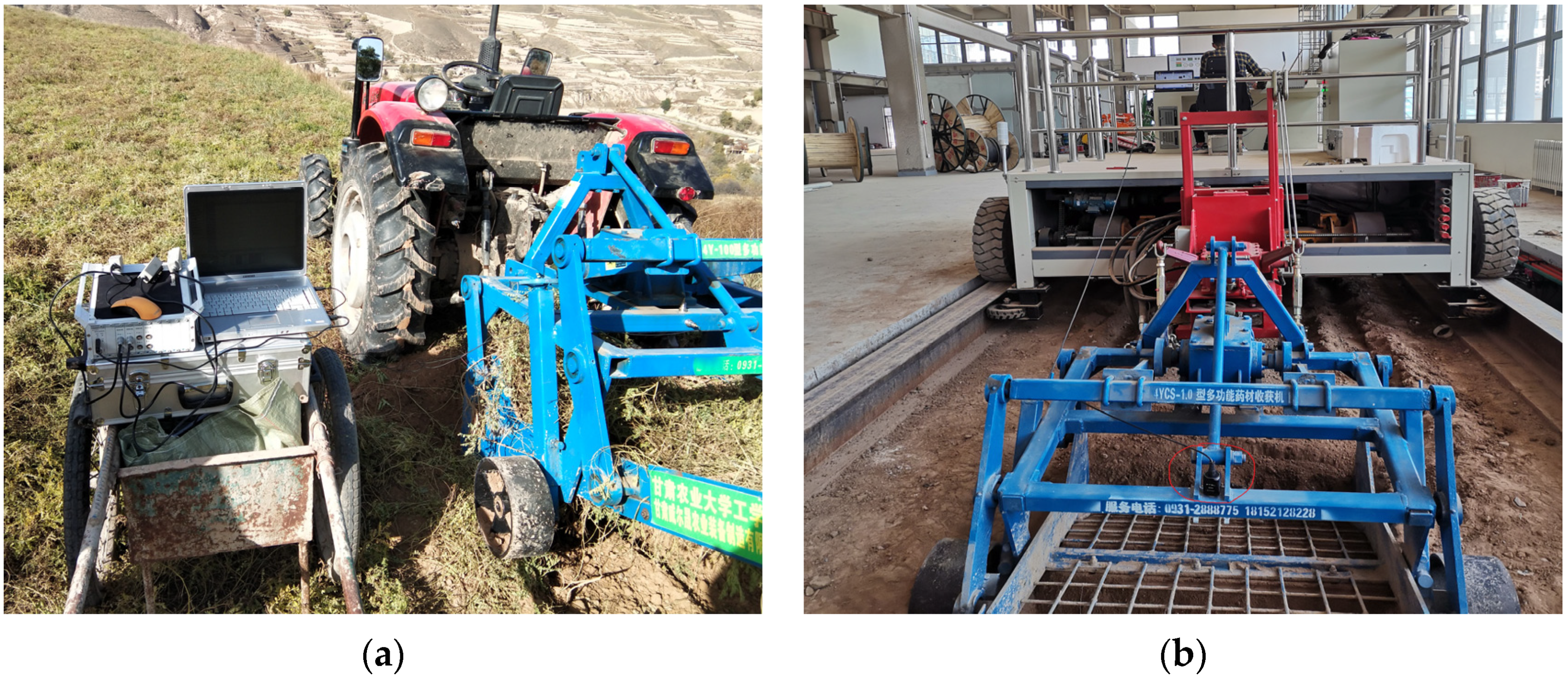
2.2. Experimental Setup and Conditions
2.2.1. Test Field
2.2.2. Test Equipment
- The 4Y-100 small rhizome Chinese herbal medicine harvester, produced by Gansu Weisheng Agricultural Equipment Manufacturing Co., Ltd. in Lanzhou, China.
- A 4Y-100 small rhizome Chinese herbal medicine harvester, powered by a Dong Fang Hong MF704 tractor manufactured by YTO Co., Ltd. in Luoyang, China.
- An indoor soil bin Tcc-2.5 manufactured by Heilongjiang Agricultural Machinery Research Institute, Harbin, China.
- A vibration velocity acquisition system, Donghua DH5922D, manufactured by Donghua Testing Technology Co., Ltd. in Jingjiang, China, with a sampling rate of up to 4 kHz and a frequency response range of DC to 100 kHz (±0.5 dB) at a 4 kHz sampling frequency.
- A magneto-electric speed sensor, Donghua 2D002, is manufactured by Donghua Testing Technology Co., Ltd., Jingjiang, China, with a measurement range of 0 to 0.5 m/s and a frequency range of −3 to +1 dB within 1 to 1000 Hz.
- Donghua Test DHDAS dynamic signal acquisition and analyzing system (DSAAS) and software supplied by Donghua Testing Technology Co., Ltd. in Jingjiang, China, running on a Dell laptop computer.
2.2.3. Experimental Crops
2.2.4. Test Method
2.3. Experimental Results
3. Vibration Analysis
3.1. Vibration Analysis of the Harvesting Machine
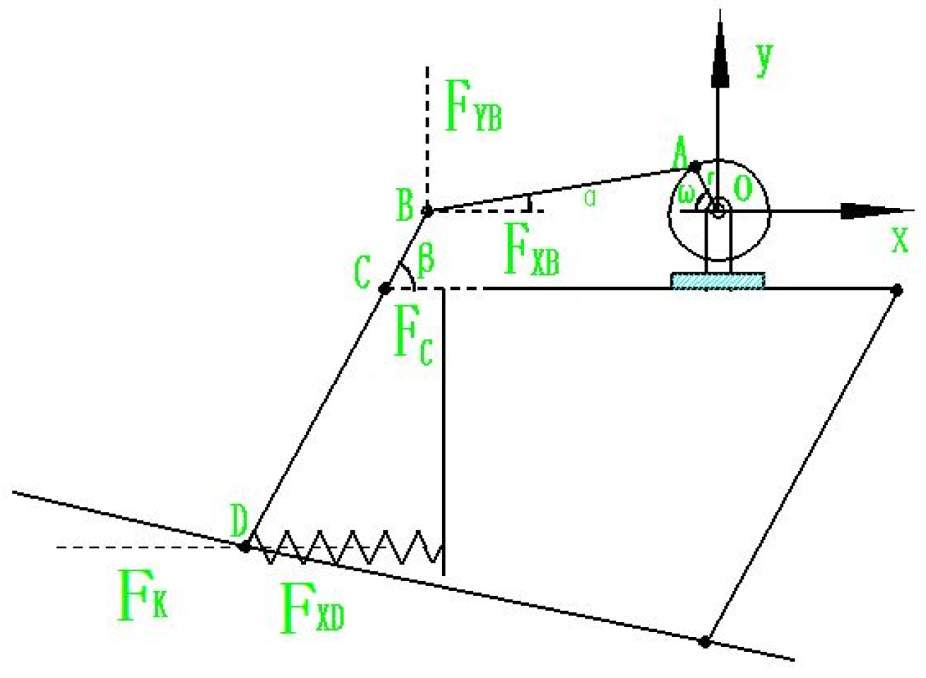
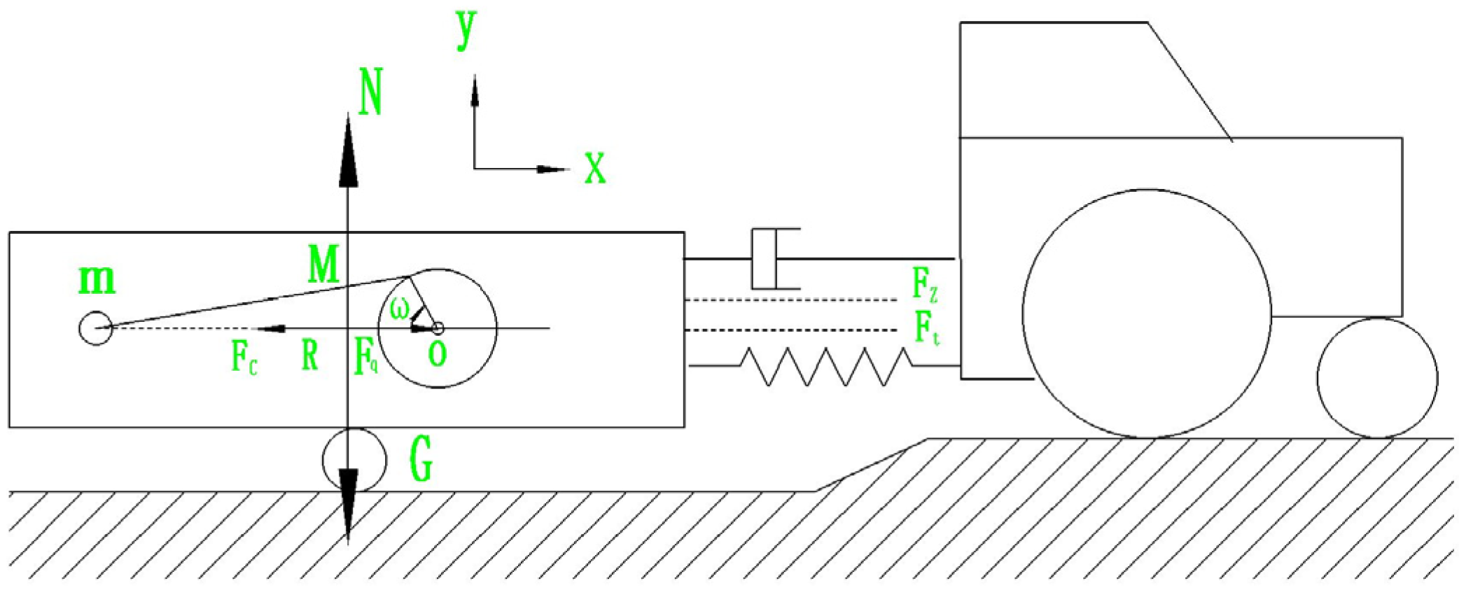
3.2. Analysis of Vibration Characteristics and Establishment of Mechanical Equations
3.3. Establishment of the Vibration Equation for the Harvester
4. Results
4.1. Effect of Tractor PTO Speed on Vibration Velocity
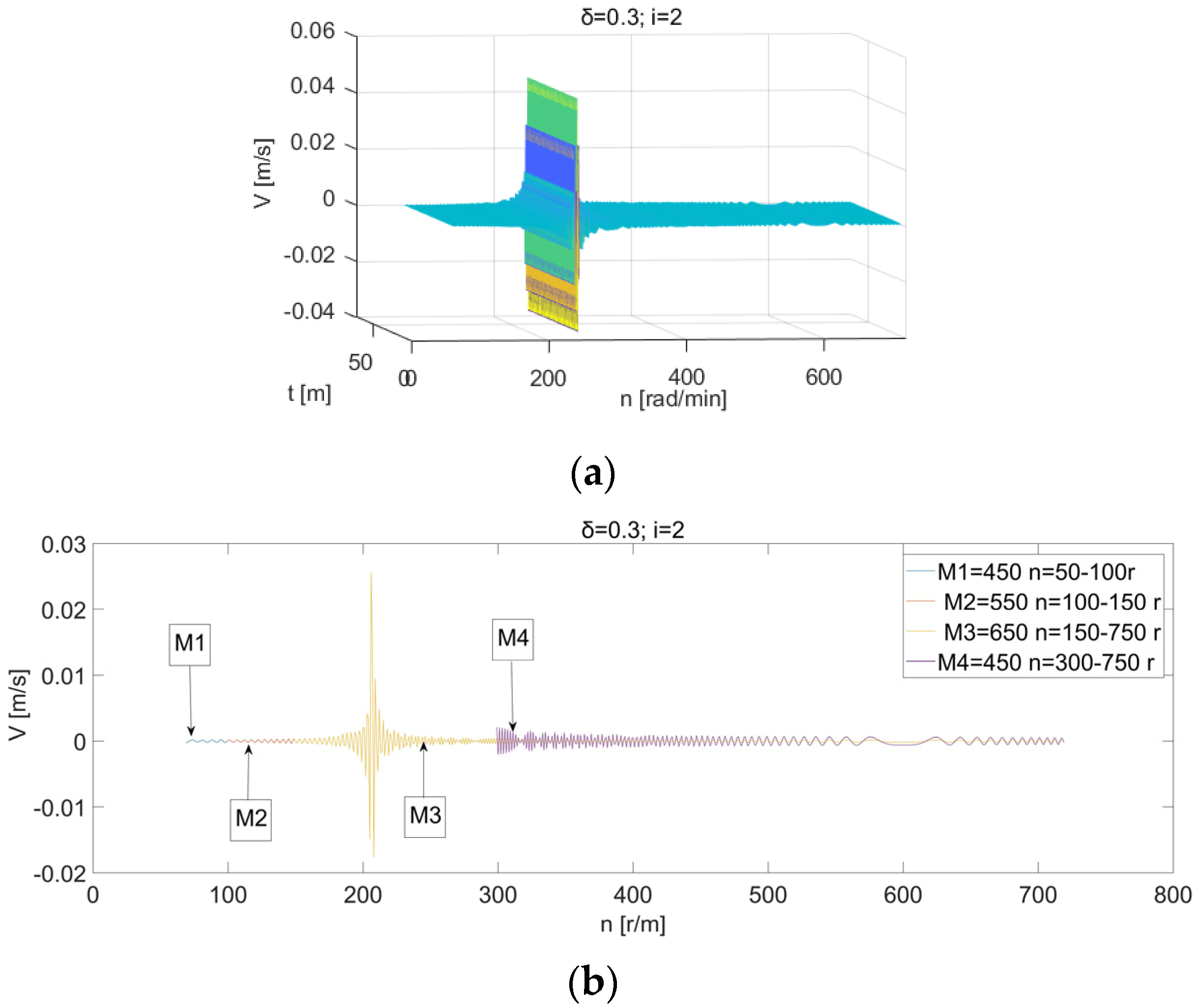
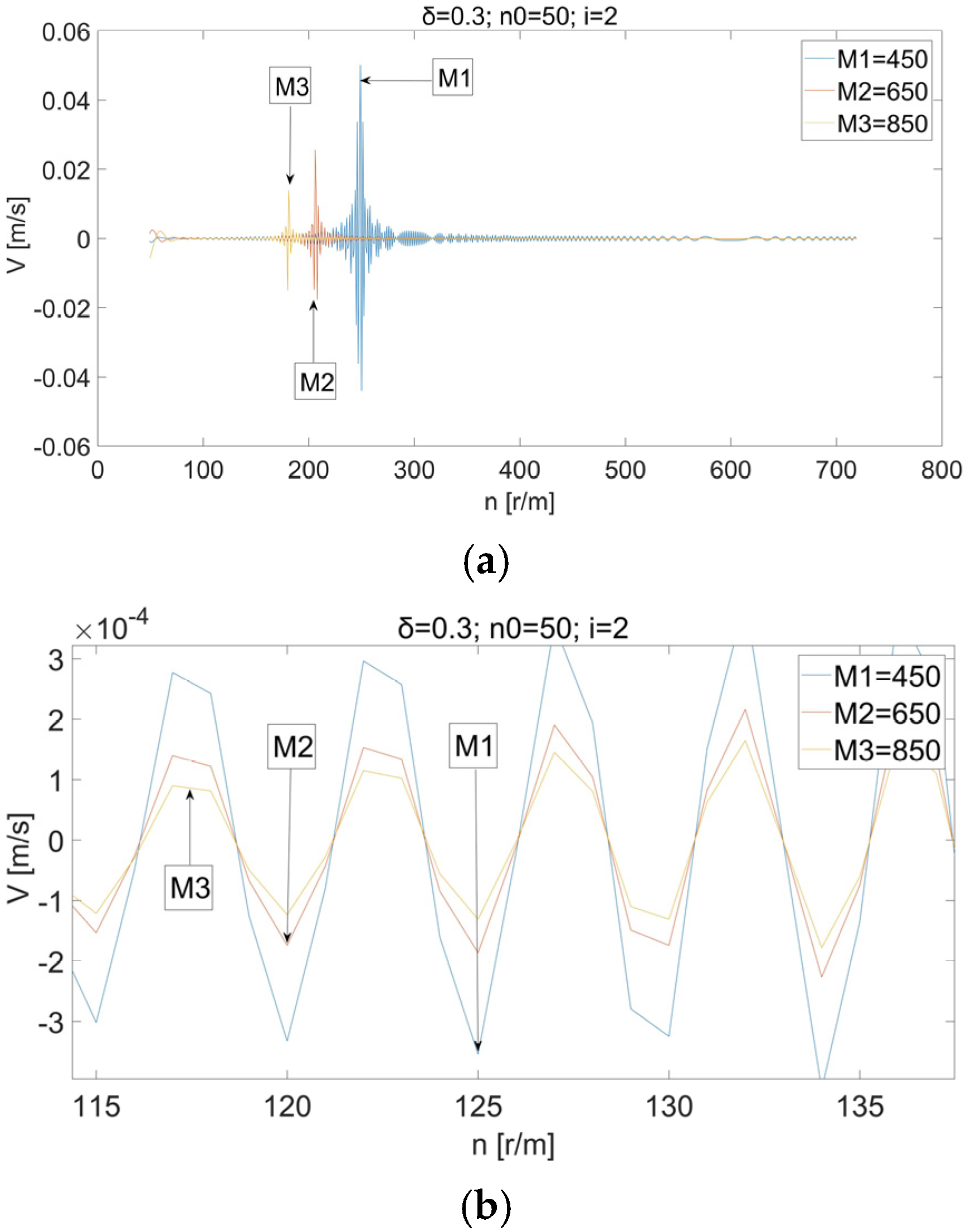
4.2. Effect of Mass M on Vibration Velocity
4.3. Effect of Stiffness k on Vibration Velocity
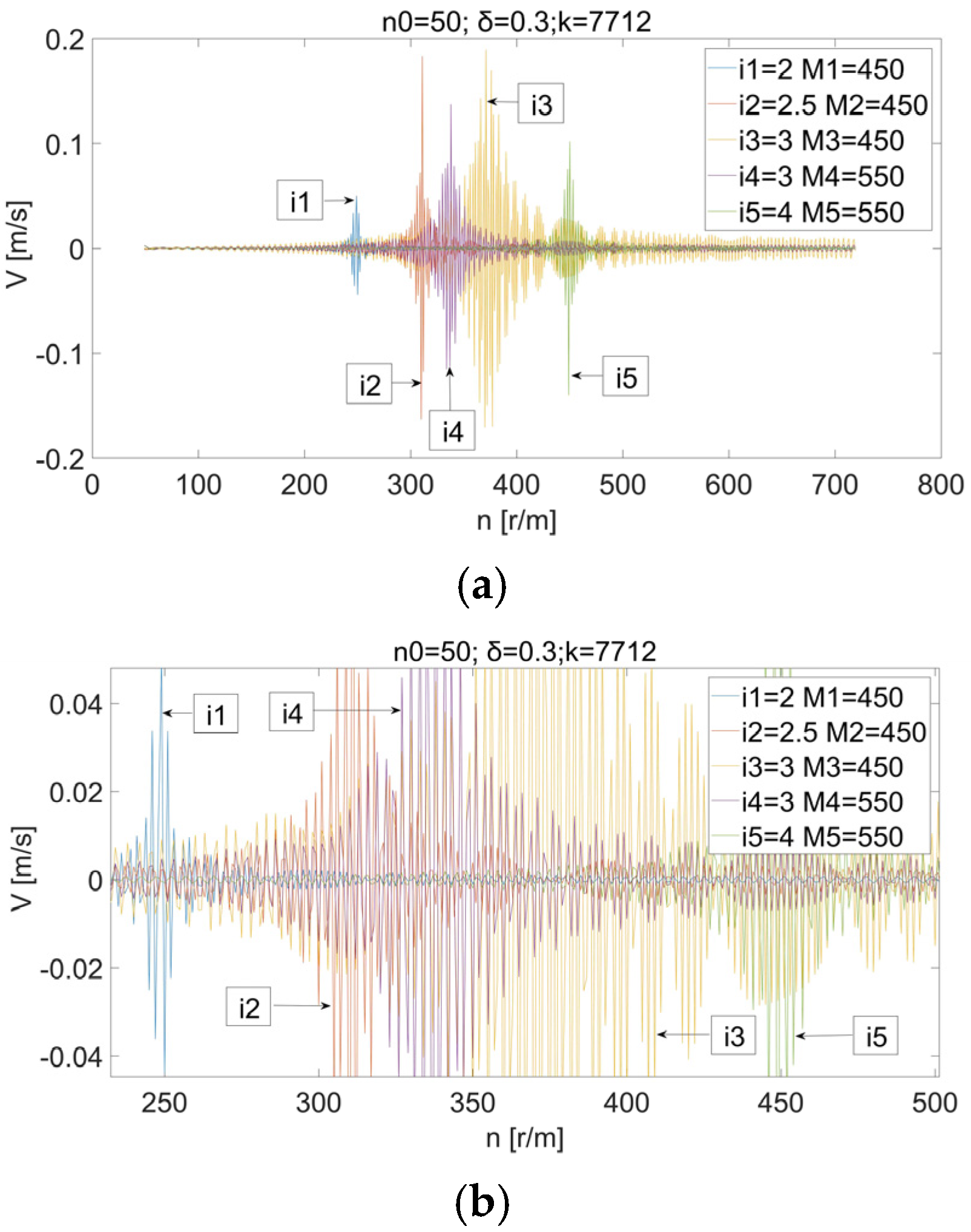
4.4. Effect of Transmission Ratio i on the Distribution of the Resonance Zone
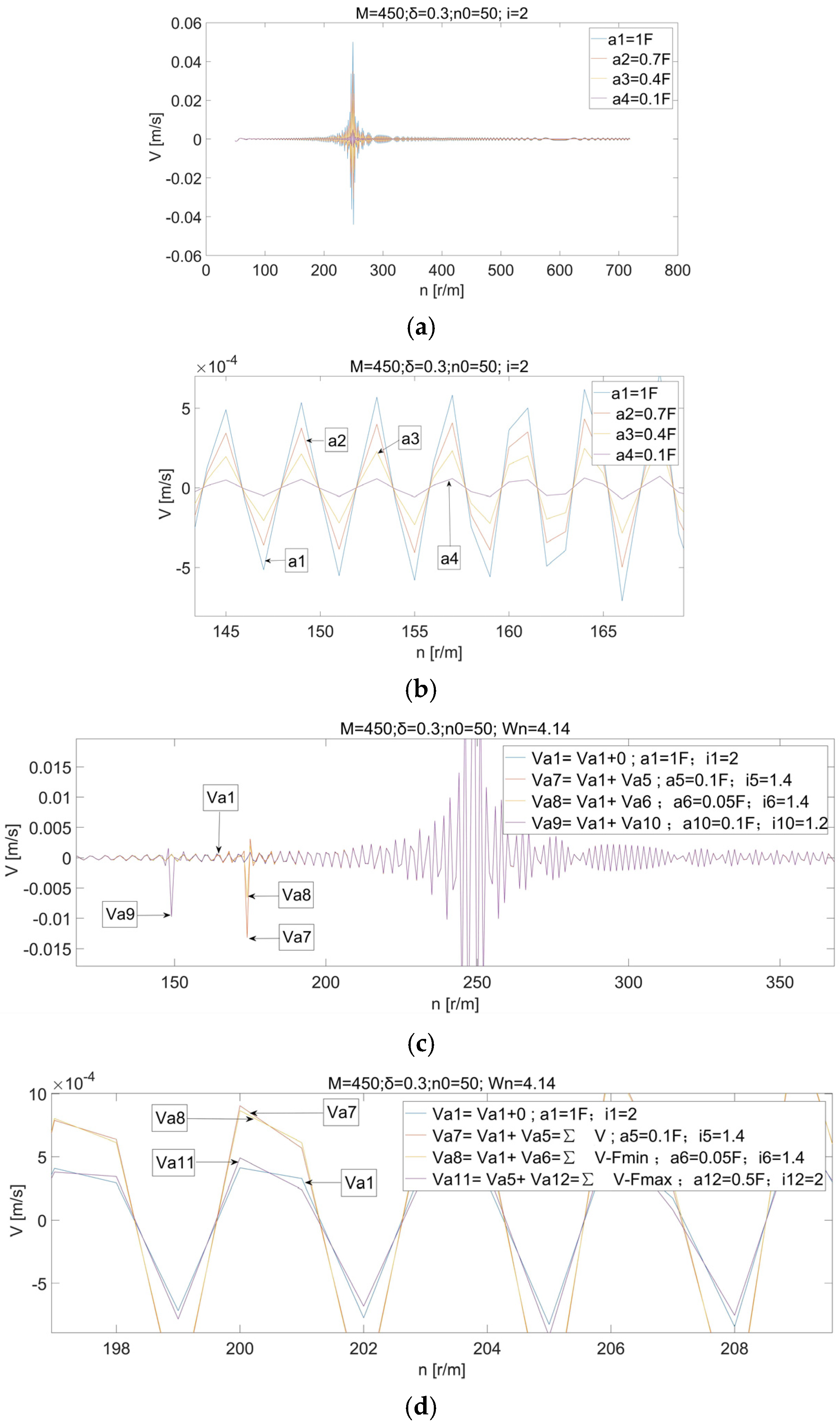
4.5. The Relationship Between Excitation Force Fc Variation and Vibration Velocity
5. Discussion
6. Conclusions
- (1)
- Before the improvement, the vibration speed of the harvester was high in both the resonant and non-resonant states. The machine was sometimes in resonance in the working state, which was the main reason for damage and poor working reliability. In the operating mode, the harvester intrinsic period is a variable value.
- (2)
- The PTO rotational speed affecting resonance in the harvester is proportional to its transmission ratio. In the case of changes in the inherent frequency of the harvester, resonance can be avoided by a reasonable choice of transmission ratios. To reduce vibration and prevent resonance, the PTO output speed should be controlled. Reducing the mass of reciprocating moving parts reduces the speed of vibration. Reducing the vibration speed of the harvester in the non-resonant state can be achieved by increasing the mass of the machine. Except for the resonance area, the vibration speed of the harvesting machine is inversely proportional to the total mass of the harvesting machine. Increasing stiffness enhances vibration resistance. The excitation force from reciprocating parts is proportional to the vibration velocity. Modification of harvester structural parameters can change this force.
- (3)
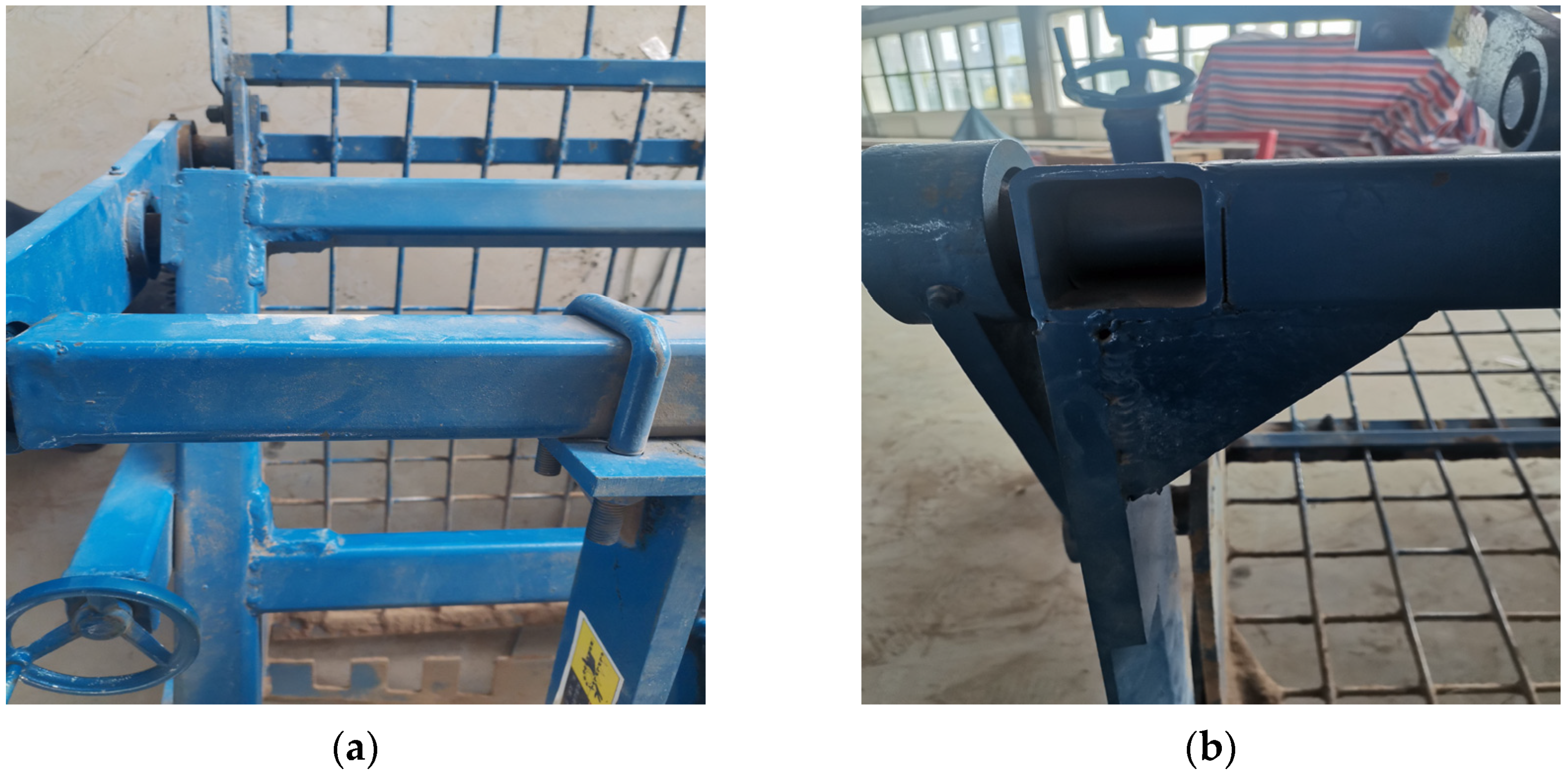
- Increase the weight of the machine under operating conditions by loading sandbags onto a frame that has no relative motion to the harvester and can bear weight stably. The moving parts on the harvester reduce the mass of the moving parts while ensuring the stiffness and strength of the parts and their dynamic equilibrium; expand the range of choices of ratios for the harvester under operating conditions; and all of the above engineering measures reduce the vibration speed of the harvester and help to prevent the occurrence of resonance.
Author Contributions
Funding
Institutional Review Board Statement
Data Availability Statement
Conflicts of Interest
References
- Dai, T.; Sun, W.; Zhang, H.; Liu, X.L.; Li, H. Research status and development trend of mechanized harvesting of rhizomatous Chinese Medicinal Materials. J. For. Mach. Woodwork. Equip. 2023, 51, 4–8. [Google Scholar]
- Wang, Z.Y.; Liu, X.L.; Zhang, H.; Xin, R.F. Current situation and prospect of mechanized harvesting of rhizome Chinese medicinal materials. J. For. Mach. Woodwork. Equip. 2024, 52, 13–19. [Google Scholar]
- Chen, L.; Qi, Y.Z.; Gao, B.; Zhang, Y.Z.; Zhang, B.H. Design of Excavating Device for Vibrating Herbal Rhizome Harvester. J. Agric. Mech. Res. 2024, 46, 120–127. [Google Scholar]
- Zhang, X.J.; Dai, F.; Shi, R.J.; Zhao, W.Y.; Ma, H.J.; Zhao, X.P. Design and Experiment of Vibrating Separating Rhizome Harvesting Machine for Chinese Medicinal Materials. J. Agric. Res. Arid Areas 2024, 42, 264–275. [Google Scholar]
- Takashi, F.T.; Inoue, E.; Mitsuoka, M. Collision vibration characteristics with interspace in knife driving system of combine harvester. J. Eng. Agric. Environ. Food 2012, 5, 115–120. [Google Scholar]
- Wang, F.; Cao, X.H.; Guo, W.J. Research on vibration strength and frequency structure of main driver seat of the wheat combine. J. Trans. Chin. Soc. Agric. Mach. 2007, 38, 62–65. [Google Scholar]
- Fu, Y.; Wang, C.G. Experiment and study of the vibration of type 4SW-170 potato digger. J. Agric. Mech. Res. 2013, 35, 147–151. [Google Scholar]
- Zhu, S.; Xu, G.; Yuan, J.; Ma, J.; Li, K. Influence of Implement’s Mass on Vibration Characteristics of Tractor-implement System. J. Trans. Chin. Soc. Agric. Eng. 2014, 30, 30–37. [Google Scholar]
- Yao, Y.; Song, Z.; Du, Y.F. Analysis of Vibration Characteristics and Its Major Influenced Factors of Header for Corn Combine Harvesting Machine. J. Trans. Chin. Soc. Agric. Eng. 2017, 33, 40–49. [Google Scholar]
- Xu, L.Z.; Li, Y.M.; Sun, P.P.; Pang, J. Vibration Measurement and Analysis of Tracked-whole Feeding Rice Combine Harvester. J. Trans. Chin. Soc. Agric. Eng. 2014, 30, 49–55. [Google Scholar]
- Chowdhury, M.; Islam, M.; Islam, S. Analysis of overturning and vibration during field operation of a tractor-mounted 4-row radish collector toward ensuring user safety. J. Mach. 2020, 8, 77. [Google Scholar] [CrossRef]
- Wang, Y.; Zhang, W.H.; Luo, X.W. Effect of Vibration Conditions on the Seed Suction Performance of an Air-Suction Precision Seeder for Small Seeds. J. Agric. 2024, 12, 559. [Google Scholar] [CrossRef]
- Adam, S.; Nawal, A. Vertical Suspension Seat Transmissibility and SEAT Values for Seated Person Exposed to Whole-body Vibration in Agricultural Tractor Preliminary Study. J. Procedia Eng. 2017, 170, 435–442. [Google Scholar] [CrossRef]
- Xin, L.L.; Li, C.Q.; Liang, J.H. Vibrating Drag Reduction Considering Acting Force of Piecewise Soil. J. Trans. Chin. Soc. Agric. Mach. 2014, 45, 136–140. [Google Scholar]
- Qiu, L.H.; Li, B.F. Experimental Study on the Self-excited Vibration Subsoiler for Reducing Draft Force. J. Trans. Chin. Soc. Agric. Mach. 2000, 16, 72–76. [Google Scholar]
- Zhang, H.H. Dynamic Behavior Analysis of Vibrating Screen of Potato Harvester. J. Contemp. Farm. Mach. 2019, 7, 68–69. [Google Scholar]
- Inoue, E.J.; Mitsuoka, M.S. Mechanical Model and Verification of the Driving Part of Combine Blade. J. Soc. Agric. Mach. 2004, 66, 61–67. [Google Scholar]
- Chen, S.; Zhou, Y.; Tang, Z. Modal vibration response of rice combine harvester frame under multi-source excitation. Biosyst. Eng. 2020, 194, 177–195. [Google Scholar] [CrossRef]
- Zheng, E.; Zhong, X.; Zhu, R.X.; Cui, S. Investigation into the vibration characteristics of agricultural wheeled tractor-implement system with hydro-pneumatic suspension on the front axle. J. Biosyst. Eng. 2019, 186, 177–195. [Google Scholar] [CrossRef]
- GB 6075–85; The Basis for Laying Down Standards of Vibration of Machines. China Standard Press: Beijing, China, 1985; pp. 4–6.
- Zhang, J. Mechanical Fault Diagnosis Technology, 1st ed.; China Machine Press: Beijing, China, 2018; pp. 8, 98. [Google Scholar]
- Zhao, Y.Z. Simplified Calculation of Natural Frequency of Microvibration for Single-degree-of-freedom Systems. J. Dalian Railw. Univ. 1986, 22, 10–16. [Google Scholar]
- Wang, Z.J.; Luo, Y.S.; Wang, R.R.; Yang, L.G.; Tan, D.Y. Experimental Study on Dynamic Shear Modulus and Damping Ratio of Undisturbed Loess in Different Regions. J. Chin. J. Geotech. Eng. 2010, 32, 1464–1469. [Google Scholar]
- Li, Z.Z. Discussion on the Condition Without Collision Between Vibrating Shovel Bottom of the Vibrating Screen Potato Excavator with the Soil. J. Trans. Chin. Soc. Agric. Eng. 1963, 6, 47–50. [Google Scholar]
- Chen, R. Simple Analysis of the Dynamics of Frog Rammer. J. Sci. Technol. Innov. 2015, 16, 34. [Google Scholar]
- Chi, Z.G.; Luan, H.L.; Jin, P. Discussion on Vibration Control Method of Drum Washing Machine Without Balance Weight. J. Electromech. Prod. Dev. Innov. 2021, 34, 101–102+110. [Google Scholar]
- Xu, K.; Li, F.; An, Q.; Li, J. Research on Dynamic Performance of Container Flat Car Body Based on the Car Body Stiffness. J. Mech. Eng. 2018, 54, 143–150. [Google Scholar] [CrossRef]
- Wei, T.; Li, M.; Huang, H.; Long, Y.; Liu, X. Bus Rear High Floor Skeleton Design Based on Response Surface Optimization. J. Mach. Des. Res. 2022, 38, 161–167. [Google Scholar]
- Zhang, D.P.; Zhang, Q.M. Analysis of Bus Body Structure. J. Chang. Univ. (Nat. Sci. Ed.) 2002, 4, 66–69. [Google Scholar]
- Ding, Y.C.; Zhao, W.Z. Stiffness Coordination Strategy for Increasing Fatigue Life and Its Application in Welded Structure. J. Trans. China Weld. Inst. 2007, 28, 31–34+114. [Google Scholar]
- Shen, Q.G.; Zheng, S.Y. Equipment Fault Diagnosis, 1st ed.; Chemical Industry Press: Beijing, China, 2006; p. 42. [Google Scholar]
- Li, Y.T. Theory and Application of Mechanical Vibration, 1st ed.; Science Press: Beijing, China, 2012; p. 252. [Google Scholar]
- Aurizi, M.; Lochmann, R.; Zuo, T.M. Composite Piston Pin—A New Concept of Lightweight Design. J. Foreign Intern. Combust. Engine 2016, 48, 38–41. [Google Scholar]
- Zhang, Y.H.; Liu, H.H.; Wang, D.C. Spring Manual, 1st ed.; China Machine Press: Beijing, China, 2008; p. 385. [Google Scholar]
- Shan, G.; Mu, P.; Xu, J. Finite Element Analysis and Optimization Design for Air Conditioner Pipeline Systems. J. Noise Vib. Control 2017, 37, 26–30. [Google Scholar]
- Zhang, M.; Li, H.J.; Wang, J.R. A New Method for Modifying the Dynamic Characteristics of Structures. J. Eng. Mech. 2009, 26, 48–55. [Google Scholar]
- Holl, H.J. Vibration Amplitude Reduction Applying Suitable Variable Excitation Frequency. Mater. Today Proc. 2023, 93, 785–790. [Google Scholar] [CrossRef]
- Luo, B.; Pan, D.; Cai, H.; Mao, X.; Peng, F.; Mao, K.; Li, B. A method to predict position-dependent structural natural frequencies of machine tool. Int. J. Mach. Tools Manuf. 2015, 92, 72–84. [Google Scholar] [CrossRef]
- Zhang, M.; Li, H.J.; Wang, J.R. A new modification method for structural dynamic characteristics. J. Eng. Mech. 2009, 26, 10–14. [Google Scholar]
- Zhu, S.X. Mechanical Design, 1st ed.; Chongqing University Press: Chongqing, China, 2019; p. 108. [Google Scholar]


| Device Name | Parameter | Parameter Value |
|---|---|---|
| 4Y-100 small rhizome Chinese herbal medicine harvester | Overall length × width × height (mm) | 3500 × 1300 × 1500 |
| Mating power (kW) | 44–58.8 | |
| Working width (mm) | 1000 | |
| TCC-2.5 indoor soil bin | Working width (mm) | 2500 |
| Motor drive power (kW) | 90 | |
| Hydraulic motor speed range (rpm) | 2–2000 |
| Field Type | Items | Parameter Value |
|---|---|---|
| Field harvesting | Average soil moisture content (%) | 12.8 |
| Average soil firmness (kPa) | 635.2 | |
| Permissible soil weight (g/cm3) | 1.21 | |
| Indoor soil bin | Average soil moisture content (%) | 11.3 |
| Average soil firmness (kPa) | 737.5 | |
| Permissible soil weight (g/cm3) | 1.31 |
| Harvester Status | Resonance Band Peak Frequency Hz | Vibration Velocity Vmax (mm/s) | Vibration Speed Mean Square Value VRMS (mm/s) | |
|---|---|---|---|---|
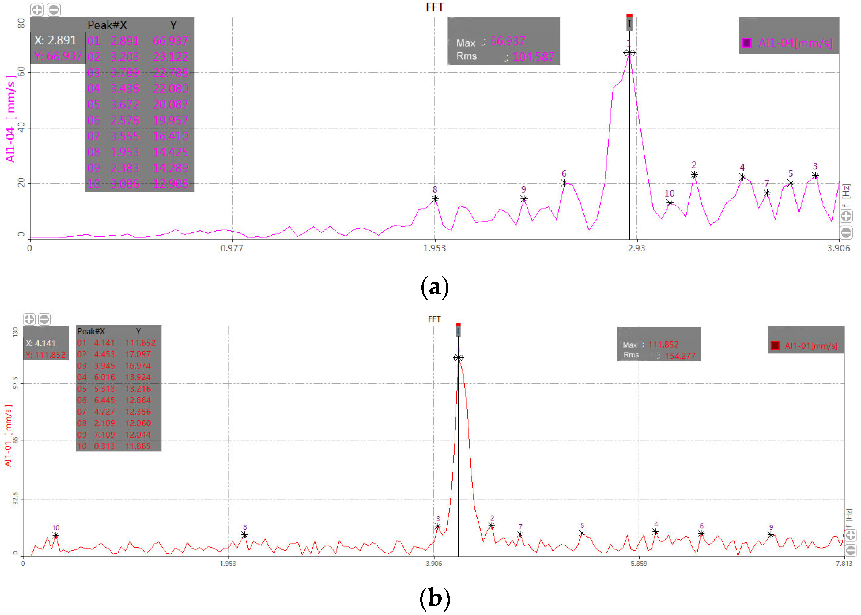
| 1 | Tractor machine traction drive work mode before improvement | 2.89 | 66.931 | 104.58 |
| 2 | The harvester is driven by the tractor, suspended off the ground by the tractor, and the harvester is in a non-working idling state. | 4.14 | 118.85 | 154.277 |
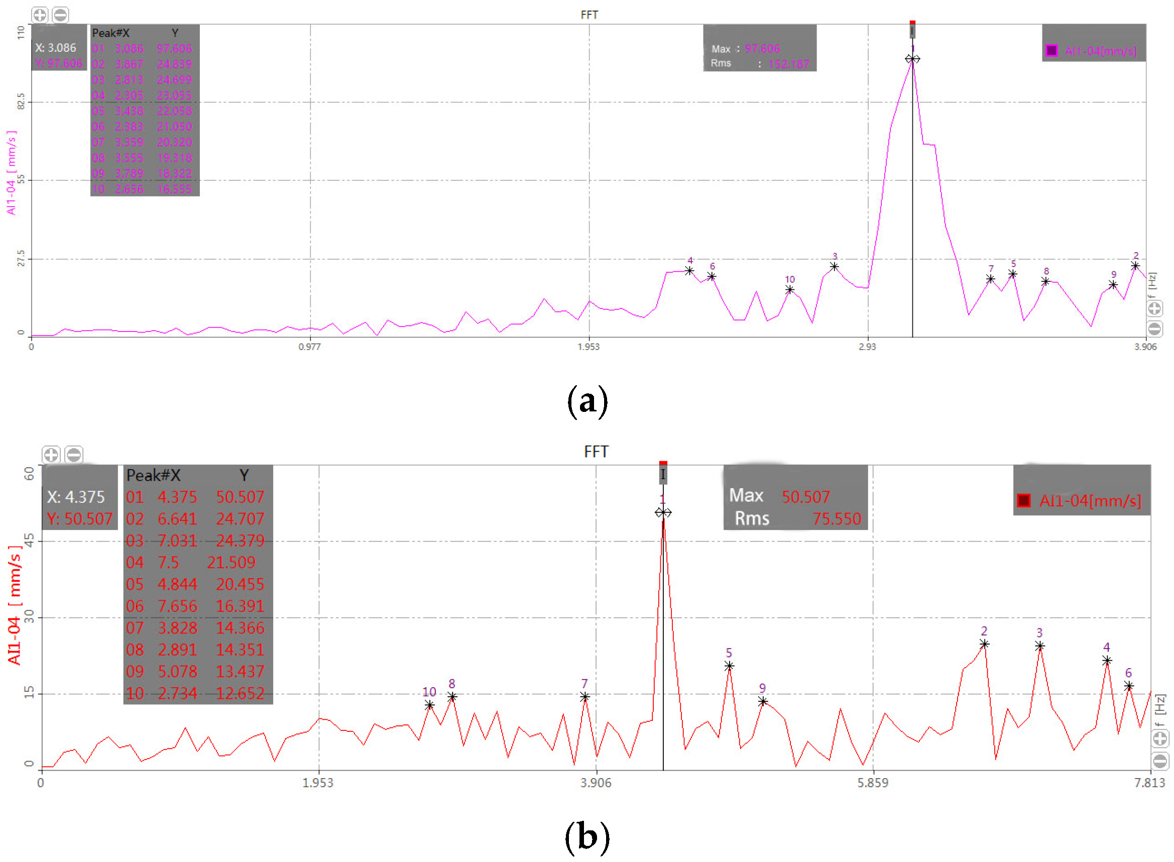
| 3 | Work mode of the traction drive of the indoor soil bin testing machine before improvement | 3.086 | 97.606 | 152.187 |
| 4 | The non-working, idling state of the indoor soil bin testing machine without spring | 4.219 | 170.664 | 268.759 |
| Harvester Status | Resonance Band Peak Frequency Hz | Vibration Velocity Vmax (mm/s) | Vibration Speed Mean Square Value VRMS (mm/s) | |
|---|---|---|---|---|
| 1 | Work mode of the traction drive of the indoor soil bin testing machine before improvement | 3.086 | 97.606 | 152.187 |
| 2 | When the indoor soil bin testing machine is traction-driven, the harvester is loaded with a 50 kg counterweight for testing. | 2.656 | 21.878 | 37.465 |
| 3 | When the indoor soil bin testing machine is traction driven, the harvester is loaded with a 100 kg counterweight for testing. | 2.559 | 12.340 | 27.818 |
| 4 | When the indoor soil bin testing machine is traction driven, the harvester is loaded with a 150 kg counterweight for testing. | 2.461 | 9.431 | 22.128 |
| Harvester Status | Resonance Band Peak Frequency Hz | Vibration Velocity Vmax (mm/s) | Vibration Speed Mean Square Value VRMS (mm/s) | |
|---|---|---|---|---|
| 1 | The harvester is driven by the tractor, suspended off the ground by the tractor, and the harvester is in a non-working idling state. | 4.14 | 118.85 | 154.277 |
| 2 | After the stiffness of the harvester is altered, the harvester is driven by the tractor, suspended off the ground by the tractor, and the harvester is in a non-working idling state. | 5.352 | 91.997 | 94.607 |
| 3 | Work mode of the traction drive of the indoor soil bin testing machine before improvement | 3.086 | 97.606 | 152.187 |
| 4 | Harvester structural reinforcement stiffness changes; the state of traction-driven operation of indoor soil bin tester | 4.945 | 32.576 | 50.836 |
| Harvester Status | Resonance Band Peak Frequency Hz | Vibration Velocity Vmax (mm/s) | Vibration Speed Mean Square Value VRMS (mm/s) | |
|---|---|---|---|---|
| 1 | Work mode of the traction drive of the indoor soil bin testing machine before improvement | 3.086 | 97.606 | 152.187 |
| 2 | The working status of the traction drive of the indoor soil bin testing machine after adding a spring to the harvesting machine | 3.086 | 48.805 | 107.554 |
| 3 | The non-working, idling state of the indoor soil bin testing machine without spring | 4.219 | 170.664 | 268.759 |
| 4 | Under the traction drive of the indoor soil bin test machine, the improved harvester, equipped with springs and a 100-kg counterweight, undergoes a non-working, idling state test. | 3.203 | 10.814 | 15.414 |
| 5 | The improved harvester, equipped with springs and a 100-kg counterweight, undergoes a working state test under the traction drive of the indoor soil bin test machine. | 4.375 | 50.507 | 75.550 |
Disclaimer/Publisher’s Note: The statements, opinions and data contained in all publications are solely those of the individual author(s) and contributor(s) and not of MDPI and/or the editor(s). MDPI and/or the editor(s) disclaim responsibility for any injury to people or property resulting from any ideas, methods, instructions or products referred to in the content. |
© 2024 by the authors. Licensee MDPI, Basel, Switzerland. This article is an open access article distributed under the terms and conditions of the Creative Commons Attribution (CC BY) license (https://creativecommons.org/licenses/by/4.0/).
Share and Cite
Dai, L.; Sun, W.; Simionescu, P.A.; Sun, B.; Huang, Z.; Liu, X. Improving Dynamic Performance of a Small Rhizome Chinese Herbs Harvesting Machine via Analysis, Testing, and Experimentation. Agriculture 2024, 14, 1888. https://doi.org/10.3390/agriculture14111888
Dai L, Sun W, Simionescu PA, Sun B, Huang Z, Liu X. Improving Dynamic Performance of a Small Rhizome Chinese Herbs Harvesting Machine via Analysis, Testing, and Experimentation. Agriculture. 2024; 14(11):1888. https://doi.org/10.3390/agriculture14111888
Chicago/Turabian StyleDai, Lixun, Wei Sun, Petru Aurelian Simionescu, Bugong Sun, Zongpeng Huang, and Xiaolong Liu. 2024. "Improving Dynamic Performance of a Small Rhizome Chinese Herbs Harvesting Machine via Analysis, Testing, and Experimentation" Agriculture 14, no. 11: 1888. https://doi.org/10.3390/agriculture14111888
APA StyleDai, L., Sun, W., Simionescu, P. A., Sun, B., Huang, Z., & Liu, X. (2024). Improving Dynamic Performance of a Small Rhizome Chinese Herbs Harvesting Machine via Analysis, Testing, and Experimentation. Agriculture, 14(11), 1888. https://doi.org/10.3390/agriculture14111888