Abstract
In the process of orchard mechanization, passability serves as a crucial criterion for evaluating the effectiveness of the chassis. To address the adaptability of hilly and mountainous multifunctional work machines to complex terrain, a theoretical analysis was conducted to assess the chassis’ performance under three key working conditions: climbing, crossing obstacles, and crossing trenches. Using kinematics, the theoretical maximum climbing angle, maximum obstacle height, and maximum trench width were calculated to be 35.8°, 170.4 mm, and 427 mm, respectively. Additionally, the passability of the chassis model was simulated under these working conditions in different soil environments using RecurDyn dynamics software. Post-processing techniques were employed to extract time characteristic curves for parameters such as center-of-mass velocity, pitch angle, offset, lateral inclination angle, and longitudinal displacement, providing valuable insights into how these parameters changed during chassis movement. The results revealed that the maximum gradient for slope climbing was 30°, the maximum height for obstacle crossing was 150 mm, and the maximum width for trench crossing was 400 mm. The prototype was then tested under these theoretical and simulated conditions in the field, and its ability to smoothly traverse slopes with a 35° angle in first gear, climb vertical obstacles up to a height of 200 mm, and pass through trenches with a width of 430 mm was demonstrated. The crawler chassis exhibited stable performance within the design parameters, aligning closely with the simulated and theoretical expectations. Overall, this study provides valuable theoretical insights for the structural design of multipurpose chassis suitable for orchards in hilly and mountainous regions.
1. Introduction
According to statistics, China, the leading country in fruit production, had a fruit tree planting area of up to 1.19 × 10⁷ hm2 in 2018 [1,2]. This expansive plantation area is predominantly distributed in regions characterized by hilly and mountainous terrain due to distinct geographical conditions and specific planting patterns. Despite this remarkable scale of fruit production, the overall level of orchard mechanization remains relatively low, at less than 20%. With the rapid economic development and the support of relevant national policies, China has been steadily advancing its agricultural mechanization efforts in hilly areas. In fact, in 2017–2018, the government put forth a crucial proposal calling for the acceleration of development in agricultural and forestry machinery and equipment specifically tailored to suit the unique needs of hilly and mountainous regions. Furthermore, there was an emphasis on strengthening the independent research and development capabilities of core agricultural machinery components. Given these circumstances, it is evident that the design and implementation of a versatile chassis suitable for orchards in hilly areas hold immense significance and potential impact [3,4].
The unique characteristics of hilly mountain orchards, including their small plot sizes and intricate terrain, pose significant challenges for traditional general-purpose chassis. These chassis exhibit limited adaptability, stability, and passability when operating in such environments, thereby giving rise to substantial safety concerns. In contrast, crawler-type universal chassis have the advantages of low grounding ratio pressure, strong adaptability to terrain, and large traction force and are currently the most widely used form in hilly areas [5].
In response to the aforementioned challenges, experts in the agricultural machinery industry have conducted extensive research. Scholars, in particular, have analyzed the structure of chassis with the aim of enhancing their passability and formal stability. Mżyk A et al. [6] analyzed the suspension system of high-speed tracks when working in rugged terrain, proposed a model of high-speed track suspension system, and explored the effect of different tensioning forces on the driving performance of tracked vehicles through simulation. The results showed that the longitudinal dimension was reduced by 27% compared with the traditional harvester. Lv K [7] et al. examined the conversion system of tracked chassis moving-part parameters in conjunction with track perimeter. They proposed a track perimeter modeling method tailored to different terrains. The designed and manufactured a complete machine, which was then tested on various terrains, covering a distance of 1000 km. The results of this test aligned with those of the previously conducted reliability test, reinforcing the validity of the proposed design method. Chen et al. [8] designed a tracked thermal fogger that can adapt to complex terrain and environments and analyzed the traction, steering, and barrier-crossing performance of the chassis on heavy clay and sandy soil roads. The results revealed that the traction performance and chassis unilateral braking turning stability enhanced with a decrease in soil deformation index and an increase in cohesion. Sun et al. [9] developed a transport vehicle suitable for forest terrain and simulated the passing performance, with tests proving that the vehicle has strong forest passing performance and can meet the needs of forest transportation. Wang et al. [10] tested and analyzed the maneuvering performance and economic performance of a greenhouse miniature remote-controlled electric track tractor and concluded that it has good traction performance. Zhao et al. [11] analyzed the fatigue life of the track chain of an excavator operating under different working conditions by building a virtual prototype model. Wang et al. [12] simulated and experimentally investigated the crawler chassis of a multifunctional beekeeping loading box under three geological conditions and on two terrain types and derived the maximum pitch angle under different conditions. Wu et al. [13] employed RecurDyn/Track LM and Pro/E software to establish a main body model of a tracked vehicle and crawler system, the assembly of which was completed in the RecurDyn environment. They conducted dynamic simulations to acquire and scrutinize crucial parameters, including tracked vehicle speed, drive wheel torque curve, and vertical acceleration of the body’s center of gravity. These analyses played a pivotal role in assessing the stability and reliability of the tracked vehicle during operation. The outcomes obtained from this investigation offer valuable insights that can be employed as a reference for optimizing the design of tracked vehicles. Mudarisov et al. [14] configured support rollers at varying elevations in comparison to a trolley, which facilitated the attainment of a suitable geometrical shape for the track support surface structure, thereby enhancing the tracked chassis’ passability.
Another group of scholars proposed the theory of body leveling to overcome the shortcomings of poor stability and drivability exhibited by chassis systems during operation. SUN and Meng et al. [4] designed a four-bar mechanism of an attitude adjustment device to address the problem of poor stability and difficult leveling of crawler tractors, then conducted physical model tests. Hu. et al. [15] introduced an adaptive leveling system for combine harvesters, utilizing a novel four-point lift-adjustable tracked chassis. Through an analysis of the adjustment characteristics under various attitude adjustment conditions within the RecurDyn environment, the researchers investigated the working principle of the proposed adjustment mechanism. Experimental results demonstrated the system’s ability to achieve automatic leveling with an impressive accuracy of ±0.4°, thereby providing crucial technical support for the advancement of tracked vehicles. Yang and colleagues [16] proposed a three-degrees-of-freedom suspension mechanism for agricultural implements on tractors. The mechanism controls the position and attitude of the suspension frame by adjusting three active motion pairs, enabling adjustment of the position and attitude. Haun [17] invented a leveling mechanism for lawn mowers that can ensure that the body of the mower remains horizontally aligned at all times. The crawler combine harvester produced by Kubota and Daejeon in Japan compensates for the lateral tilt of the body by adjusting the height of one side of the track with a trac-lift mechanism [18,19,20]. Gonzalez et al. [21] proposed an electrohydraulic leveling technology designed to enhance the lateral stability of the tractor body and mitigate the possibility of rollovers. Ballesteros et al. [22] developed an automatic rollover protection system for tractors and conducted simulation testing using a simplified model. Sun et al. [23] proposed a leveling mechanism for a crawler-type combine harvester that can control the inclination of the vehicle or platform and prevent overturning, thus improving the machine’s efficiency when working on rugged terrain.
The force and mutual contact relationship between the track and soil has been extensively studied by scholars in order to analyze the performance of tracked ground under various ground conditions. Thomas Keller T et al. [24] introduced a model to predict the vertical stress distribution at the rubber track–soil interface to improve the accuracy of rubber-tracked agricultural vehicles in predicting soil stress and compaction risk. Andrea Nicolini et al. [25] proposed a novel compact model of track–soil interaction and realized the mechanical laws of terrain response. Francesco Mocera et al. [26] constructed a multibody model to analyze the driving characteristics of tracked chassis and used the Bekker–Janosi-Hanamoto soil mechanics equation to simulate the tracked relationship between traction force and soil.
Research on chassis specifically designed for hilly mountain orchards is relatively limited compared to other types of agricultural terrain. Cui et al. [27] designed a greenhouse electric lifting platform with walking, turning, and lifting functions for fruit and vegetable management, as well as picking and transportation problems, and investigated its turning, driving, and climbing performance, as well as the endurance time of the platform, through bench experiments and field tests, respectively. Bao et al. [28] studied a light self-propelled mountain orchard universal mobile platform to address the challenges posed by monolithic agricultural machinery in mountain orchards, such as poor versatility and uneven land. Wang [29] conducted a theoretical and simulation analysis of the passing performance for the self-developed hilly mountain orchard power chassis. Zhang et al. [30] designed an unmanned mountain orchard transport vehicle with a star wheel structure and analyzed its performance in crossing obstacles. Han et al. [31] analyzed and discussed the key structural parameters affecting the straight-line driving, differential steering, and ability to overcome obstacles on slopes of a tracked chassis and proposed a center-of-gravity adjustment system. In this paper, a multipurpose crawler chassis for orchards is designed based on the characteristics of hilly mountain orchards in Gansu, China.
This paper investigates the passing performance of a multifunctional chassis, specifically in relation to its kinematics and dynamics, under the challenging conditions presented by the hilly terrain and soil in the northwest region. A mathematical model is developed to establish relationships between various parameters, including the maximum climbing angle, barrier-crossing height across the width of a trench, barrier-crossing speed, and center-of-mass position parameter. Moreover, we analyze the time curve characteristics of the center-of-mass speed, pitch angle, lateral inclination angle, and longitudinal displacement and offset under three different working conditions through simulation. The simulation results provide valuable insights into the maximum climbing angle and barrier-crossing height across the width of a trench. Additionally, the simulation model incorporates parameters such as the maximum climbing angle, barrier height, and trench width to ensure comprehensive evaluation. Field tests are conducted in line with the characteristics of the hilly mountainous area and soil in Northwestern China to validate both the theoretical and simulation models.
2. Structural Composition and Working Principle
2.1. Structural Composition
A crawler orchard power chassis is composed of a shift control handle, brake system, engine power plant, clutch, variable-speed mechanism, hydraulic cylinder, sprocket transmission system, frame, endless track installation, and quick-change device, as shown in Figure 1. The endless track installation is responsible for enabling the chassis to move through fields and orchards. It comprises rubber tracks, drive wheels, guide wheels, supporting wheels, tensioning wheels, tensioning devices, bearing housing, and the frame. The engine power plant and gear box are mainly used to control the speed of the chassis drive wheels and the power output of the diesel engine, which is mainly composed of a diesel engine, gear box, double-row sprocket, double-row chain, transmission shaft, gear box, and bushing. The clutch is controlled by an electric push rod to complete the separation operation. The function of the frame and quick-change device is to carry working parts such as mowers, trenchers, and other implements for operation in the orchard. The hydraulic control system manages various functions, including the lifting and lowering of the equipment, the opening and closing of the quick-change device, and the fine tuning of the longitudinal depth position of the operating mechanism. The shift control handle plays a crucial role in controlling the forward and reverse gears and is conveniently located at the front part of the chassis for easy operation by the user.
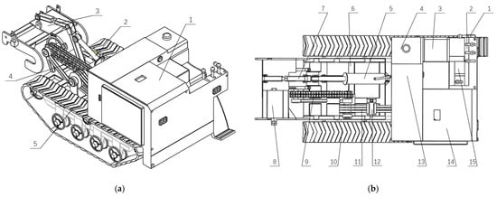
Figure 1.
Schematic diagram of the structural layout of the whole machine. (a) Isometric diagram: (1) engine; (2) hydraulic cylinder; (3) quick-change device; (4) transmission; (5) endless track installation. (b) Top view: (1) drive wheels; (2) mechanical console; (3) driving seat; (4) fuel tank; (5) integral lifting hydraulic cylinder; (6) frame; (7) hydraulic cylinder for longitudinal depth adjustment system; (8) quick-change device; (9) double row; (10); rubber tracks; (11) belt; (12) tensioning wheels; (13) hydraulic oil tank; (14) diesel engine; (15) gear box.
2.2. Working Principle and Technical Parameters
When the crawler orchard power chassis is in operation, the power flow follows a specific path. Assuming the forward direction of the machine is considered as the positive direction, the power output from the diesel engine (1) is transmitted to the clutch (2). The output shaft of the clutch is then connected to the input shaft of the gear box (4), which transfers the power to the gear box. After the power goes through the speed-change process within the gear box, it is outputted from the gear box’s output shaft and its small pulley (5). From there, the power is transmitted to the large pulley (7) through the transmission belt (6). The power that passes through the large pulley (7) is divided into two parts. One part is sent to the active sprocket (8) and the steering clutch (14). This portion of the power is further split: some of it is transferred to the driving wheel (12), driving the movement of the track via the double-row chain (11). The remaining power is transferred to the driven sprocket (10). A part of the power is transferred to the driving wheel (12) through the steering clutch (14) and drives the track movement, and another part of the power is transferred to the active sprocket (8) and is transferred to the driven sprocket (10) through the double-row chain (11). Finally, the power is transferred to the quick-changing device shaft (9), part of which is used for the load operation. The power transfer route is shown in Figure 2.
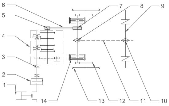
Figure 2.
Impetus transmission roadmap: (1) diesel engine; (2) clutch; (3) joint slack; (4) gear box; (5) transmission output shaft pulley; (6) belt; (7) driven pulley; (8) active sprocket; (9) input shaft of the operating device; (10) slave sprocket; (11) double row; (12) drive wheels; (13) rubber tracks; (14) steering clutch.
Combined with the current situation of hilly mountain orchards, the main technical parameters of the machine are listed in Table 1 under the premise of ensuring the quality of operation and operational safety of the machine.

Table 1.
Main technical parameters.
3. Universal Chassis Passability Theory Analysis
3.1. Slope Passability Theory Analysis
When the crawler chassis is running longitudinally uphill, its forces mainly include the component force of gravity, the ground friction force generated when driving, and the ground reaction force exerted on it, as shown in Figure 3.
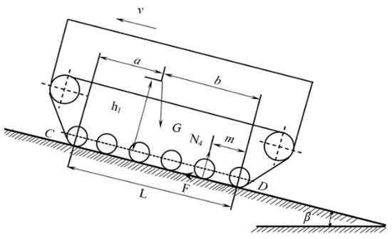
Figure 3.
Sketch of the force on the chassis when driving uphill.
As stated above, the machine is in equilibrium when climbing at a constant speed, i.e., the combined force on the machine is 0. The moments of supporting wheels C and D of the machine are taken separately, and the moment of supporting wheel D can be obtained when climbing uphill:
The combined force in the vertical direction is 0, i.e., . The above equation can be calculated as:
The condition under which the whole machine does not roll over when going uphill longitudinally is m = 0, i.e.,
By deforming the above equation, we obtain:
where βm1 is the maximum longitudinal uphill slope angle lead in ° (h = h1 + R). As shown in Figure 4, the limit of the maximum downhill slope angle of the whole vehicle is .
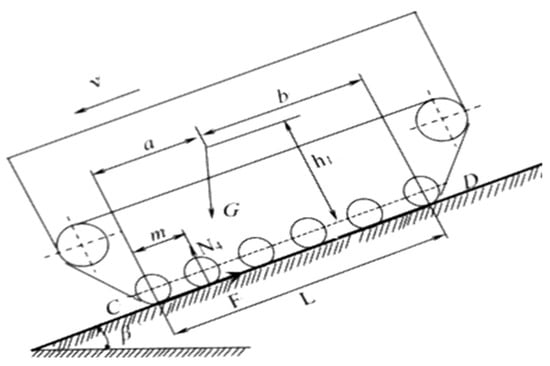
Figure 4.
Sketch of the force on the chassis when driving downhill.
As depicted in Figure 5, the key factors that influence the maximum slope angle are the height of the center of gravity (h1 + R) and the distance between the center of gravity and the supporting wheels (b for uphill and a for downhill). When b is held constant, the maximum angle (β) is inversely proportional to h. Conversely, if h remains constant, β increases with an increase in b. Based on the analysis presented above and the calculations outlined in Table 1, the chassis can ascend a maximum slope angle of 35.8°.
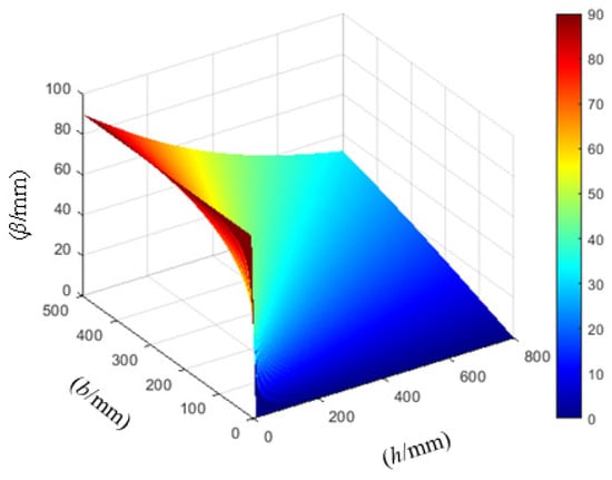
Figure 5.
Surface relationship between climbing angle and various parameters.
3.2. Theoretical Analysis of Universal Chassis Crossings of Vertical Obstacles
3.2.1. Process Analysis of Crossing Vertical Obstacles
While working in mountainous areas, crawler chassis are subjected to obstacles such as field ridges, road edges, rocks, and convex ridges. Among these, the most challenging for the chassis is vertically oriented obstacles. In this subsection, an analysis is conducted with the aim of removing vertical obstacles in the field. As the crawler chassis moves across a vertical obstacle in the field, the angle (θ) between the crawler and the ground gradually increases. Once the center of gravity of the chassis crosses the support point of the obstacle, the chassis can smoothly pass the vertical obstacle and complete the obstacle-crossing process. The process can be divided into three stages: crossing the front of the obstacle, overcoming the obstacle, and crossing the rear of the obstacle.
During the first stage of the maneuver, the front end of the track establishes close contact with the obstacle. In this stage, the chassis slowly moves forward through the field using the drive wheels of the tracked machine until it reaches the vertical wall support point. Following this, an overall rotational motion takes place. Subsequently, the sway angle of the chassis steadily rises, and the vehicle body ascends along the vertical wall, as illustrated in Figure 6a.

Figure 6.
Vertical obstacle-crossing process: (a) first stage; (b) second stage; (c) third stage.
During the second stage, the car body’s center of gravity moves to a position that coincides with the vertical wall plumb line, marking the critical state of crossing the barrier, as shown in Figure 6b. In this stage, the vehicle body experiences the following forces:
- (1)
- The gravity of the tracked chassis (G);
- (2)
- The two forces exerted on the rear support wheel by the ground: a support force (N1) and a traction force (F1);
- (3)
- The two forces exerted on the grounded track by the obstacle: a support force (N2) and a traction force (F2).
When the chassis is crossing the obstacle and reaches a critical state, it attains force equilibrium. At this point, the moment equilibrium equation for the support point (O1) is presented as follows:
The critical condition for a universal chassis to achieve its highest possible angle of elevation is met when N2 = 0. Therefore:
The maximum angle of elevation for a tracked chassis can be determined by:
The relationship connecting the height of a vertical wall obstacle (h0) and the elevation angle of a vehicle is given by:
where h0 is the vertical wall height lead in mm, R is the Radius of the supporting wheel lead in mm, R1 is the drive-wheel radius lead in mm, h1 is the normal height difference from the center of mass to the axis of the supporting wheel lead in mm, h2 is the height between the front drive wheels of the chassis and the ground lead in mm, L is the length from the track to the ground contact lead in mm, and θ is the chassis elevation angle lead in °.
This is given by:
Based on Table 1, it is evident that the vehicle can achieve a maximum elevation angle of 36.6° when crossing a barrier, as well as a maximum height of 170.4 mm when crossing the same barrier.
In the process of crossing the obstacle, if the elevation angle exceeds the limit, the crawler chassis may disengage from the outer corner line of the step, resulting in a reverse overturn or tip. Using the geometric relationship shown in Figure 6b, we establish a connection between the obstacle clearance height and the chassis’ structural parameters. We further determine the connection between the longitudinal distance (S) of the structural parameters, the angle (θ) between the chassis and the ground, and the height of the over-run (h0) through simulation using Matlab2021 calculation software, as shown in Figure 7.
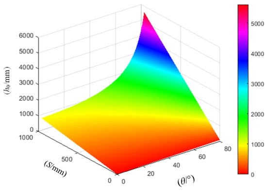
Figure 7.
The relationship between the structural parameters of the universal chassis and its over-running height.
As Figure 7 depicts, the height of the universal chassis over obstacles exhibits an upward trend in response to increases in both the angle between the chassis and the ground and the distance between the center of the tracked chassis load-bearing wheel and the longitudinal center of gravity. This trend indicates that relocating the center of gravity of the universal chassis towards the front or downward enhances the obstacle-crossing performance. However, it is important to note that the longitudinal distance between the center of gravity and the tracked chassis load-bearing wheel center is restricted by the chassis structure, and the angle between the chassis and the ground cannot be expanded infinitely.
The relation between the pitch angle (θ) and the height (h0) in the universal chassis over-running process can be plotted using Equation (8), as illustrated in Figure 8. As the chassis traverses the barrier, the height of crossing gradually increases as the chassis advances, culminating in the peak of the curve, where h0 reaches its maximum value. At this point, the pitch angle approaches 35°, and the height (hmax) is around 178 mm. Further increasing the pitch angle causes the height of crossing the barrier to decrease. Additionally, it is worth noting that the passing performance of the chassis improves as the center of gravity is positioned lower and the distance from the rear support wheel is increased.
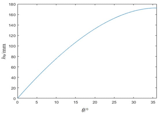
Figure 8.
The relationship between the crossing barrier height (h0) and the angle (θ).
During phase 3, the horizontal movement of the chassis’ center of gravity is undertaken to ensure complete traversal of the vertical obstacle, thereby marking the culmination of the crossing operation. The objective of this stage is to minimize the violent impact between the tracks and the ground to reduce vibrations and prevent damage to the chassis. Please refer to Figure 6c for a visual representation.
3.2.2. Trench-Crossing Passability Analysis
Trenches are common obstacles in hilly and mountainous fields, and the ability of orchard tracked chassis to cross them is a crucial performance metric.
The main factors that affect the passing performance of chassis are the support points at both ends of the tracks, the distance between the center of gravity projections on the driving surface, and the slope size. When the track’s center distance exceeds the trench’s width, the relative position of the center of gravity and the trench support point determines whether the tracked chassis can pass through the trench. The process of crossing a trench can be divided into three stages:
During phase 1, the universal chassis undergoes a slow ascent up the slope while the front section of the vehicle gradually enters the trench. The force of gravity plays a significant role, causing the front part of the chassis to naturally incline downward toward the slope and the trench. However, if the trench’s width is excessive, the front part of the vehicle may fall into the trench.
During phase 2, the universal chassis keeps moving forward until the front part of the track comes into contact with the rear edge of the trench. At this point, the rear part of the track remains in contact with the road surface at the front of the trench, and the complete machine becomes suspended above the trench.
During phase 3, the tail of the track departs from the front of the trench, leading to the vehicle body reaching its maximum pitch angle. At this point, the rear part of the vehicle body is suspended. If the trench is too wide or the slope is too steep, the complete machine may fall into the trench, rendering it unable to pass or even causing dangerous tipping failure.
In order to ensure that neither the front nor rear part of the tracked chassis falls into sloping trenches during crossing, it is imperative to undertake thorough exploration and analysis during both the initial and final stages of the crossing process. Figure 9 depicts a schematic diagram of the maximum width of sloping trenches that the tracked chassis can traverse. By determining the vertical projection of the chassis center of gravity falling in safety level 0 (hereafter referred to as point P) as the critical condition, the maximum widths (H1 and H2) that the tracked chassis can cross in the two cases depicted in Figure 9 can be determined as follows:
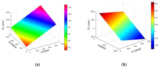
Figure 9.
The dimensions of the universal chassis structure versus the trench width surface: (a) surface plot of trench width H1 versus a and h1; (b) surface plot of trench width H2 versus a and h1.
Based on the analysis results obtained for the two motion positions, the maximum trench width (H) that can be crossed by the universal chassis is obtained using Equation (10) as:
The combination of Table 1 and Equation (11) yields a spanning trench width (H) of 427 mm.
The relationship equation is derived by combining Equation (10) with the geometrical relationships presented in Figure 10a,b and the structural parameters of the crawler chassis. The climbing degree angle is determined to be 30° to prevent slipping backward. Parameters such as a, h1, H1, and H2 are obtained by simulating the general chassis structural parameters using Matlab software. Figure 9a,b show the surface relationships between these parameters.

Figure 10.
Trench-crossing diagram: (a) crossing trench location 1; (b) crossing trench location 2.
Figure 9a shows that the width of the trench that can be crossed (H1) increases with higher values of a and h1. This implies that positioning the center of mass farther back and lower during the first stage enhances the chassis’ ability to traverse the trench. However, due to the chassis structure and the maximum climbing degree, a and h1 have limited capacities for increase. Figure 9b shows that H2 decreases with increases in a and h1. Taking into account the two working conditions of stage one and stage three, the maximum desirable values for H1 and H2 are the width of the widest trench that can be crossed.
4. Simulation Analysis of Universal Chassis Passage Capacity
4.1. Analysis of Driving Performance on Ground with Different Slopes
The climbing performance of a general-purpose chassis refers to its ability to safely ascend slopes while operating in first gear. The climbing performance depends on the soil type, driving speed, and location of the center of mass. In this study, Recur Dyn software, a multibody dynamics analysis tool, was employed to create and simulate two types of road surfaces—sand and clay—on which a universal chassis was tested at various inclines represented by four gradient angles: 20°, 25°, 30°, and 35° (Figure 11). Through simulation experiments conducted on both sand and clay surfaces at different inclines, time characteristic curves were obtained for three key parameters: the velocity of the center of mass (vp), the pitch angle (γp) of the center of mass, and the whole chassis’ offset (Lp) during the climb. The data collected from both road surfaces were then fitted to generate the curve depicted in Figure 12.
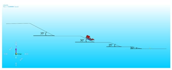
Figure 11.
Universal chassis hill-climb simulation analysis.
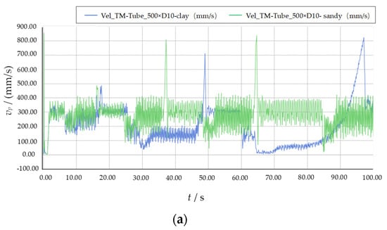
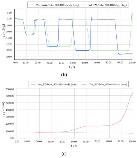
Figure 12.
Universal chassis climbing performance-time characteristic curves: (a) velocity-time characteristic curve of the center of mass; (b) pitch angle-time characteristic curve; (c) offset-time characteristic curve.
As shown in Figure 12a, the driving speed progressively decreases with an increase in slope. Specifically, on a clay surface, the chassis is able to traverse a 30° slope at a slower pace, beyond which it slowed down considerably, with almost zero velocity at 35°, experiencing increased offset and zero pitch angle. This is attributed to the critical slip of the entire chassis structure, which could cause sudden sliding. Hence, the general-purpose chassis cannot navigate a 35° clay surface. Figure 12a,b show that the chassis structure has a higher average speed on the sandy road and passes the 25° slope with greater ease than the clay road due to track slippage on the clay surface. Furthermore, Figure 12c illustrates that the sandy road surface exhibits a more stable offset and had a lower center-of-mass speed and pitch-angle fluctuation; thus, the universal chassis can safely climb a 35° slope on a sandy surface.
4.2. Analysis of Obstacle-Crossing Performance
Considering the working environment of the tracked universal chassis utilized in orchards, we conduct a simulation of the chassis’ over-run performance when rollover is absent to simulate its performance when crossing obstacles. We set up sand and clay road surfaces as described in Figure 13. We then extract the time characteristic curves for pitch angle (γz), inclination angle (δz), and center-of-mass velocity (vz) individually. The road surface curves are then fitted, as shown in Figure 14.
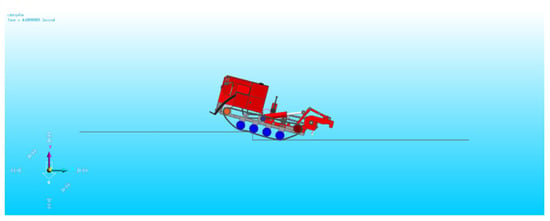
Figure 13.
Simulation analysis of universal chassis over-run performance.
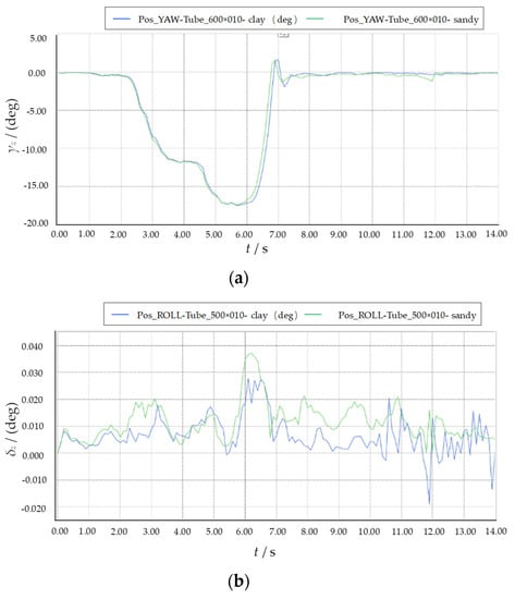
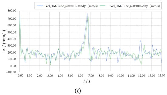
Figure 14.
Universal chassis obstacle-crossing performance-time characteristics curves: (a) pitch angle-time characteristic curve; (b) inclination angle-time characteristic curve; (c) velocity-time characteristic curve of the center of mass.
Examination of Figure 14a reveals a maximum pitch angle of approximately 17.5°, which occurs between 5 and 7 s of driving time. Importantly, this angle does not exceed the critical pitch angle, thus preventing backflip. There is no significant difference between the pitch angles observed on the two road surfaces, suggesting that the nature of the road surface does not play a prominent role in influencing γz during the process of crossing obstacles. As depicted in Figure 14b, the lateral tilt angle (δz) experiences a relatively smooth transition throughout the obstacle-crossing maneuver, with no significant fluctuations observed that may cause rollover. Figure 14c portrays vz and reveals that the characteristic curve experiences an initial rapid decrease when the guide wheel touches the obstacle, leading to a sudden decrease in vz. As the driving time reaches 5–7 s, vz rapidly increases due to the lifting of the body, which creates a sudden change in its inertia. Once the obstacle is cleared, the velocity of the mass center is restored to a stable state, satisfying the requirements for the characteristic curve in its entirety. Fluctuations in the velocity of the center of mass appear to be stronger in sandy soil, increasing the likelihood of experiencing a rigid collision under such conditions. In conclusion, the simulation proves that the chassis is capable of smoothly overcoming vertical obstacles of 150 mm in height, resulting in a difference of 20.4 mm from theoretical calculations, which is within the acceptable range of error. Therefore, the simulation can be considered effective in assessing the chassis performance in crossing obstacles.
4.3. Cross-Trench Performance Analysis
The term “performance of crossing the trench” refers to the capability of the chassis to cross the trench’s limit width at constant speed without toppling. This ability is contingent on several factors, including the type of soil, the velocity of the chassis, and the positioning of its center of mass. In this study, a trench with dimensions of 400 × 200 mm is set up to determine the passability of the chassis through simulated tests in two soil types. The employed process is demonstrated in Figure 15, with time characteristic curves of the pitch angle (γg) and longitudinal displacement Lg extracted. The data of the two soil types are then fitted to obtain the information illustrated in Figure 16.
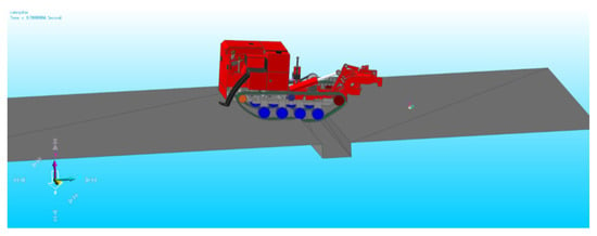
Figure 15.
Simulation analysis of universal chassis crossing trenches.
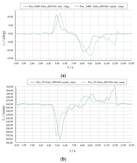
Figure 16.
Time characteristic curves of universal chassis crossing: (a) pitch angle-time characteristic curve; (b) longitudinal displacement-time characteristic curve.
The characteristic curves of γg and Lg are illustrated in Figure 16a,b, respectively. From Figure 16a, it can be observed that the complete time required for the chassis to cross the trench falls between 4 and 13 s. The analysis of both curves reveals that the appearance time of the pitch angle and longitudinal displacement varies depending on the soil type.
Specifically, in clay soil, γg and Lg tend to appear slightly earlier compared to sandy soil. However, in sandy soil, both γg and Lg exhibit slightly larger values—approximately 10% more than those obtained from the clay soil. Therefore, it is important to strictly regulate speed when crossing a ditch. Despite significant fluctuations, the machine can cross a trench with a width of 400 mm smoothly, as indicated by the whole curve trend of γg and Lg.
5. Test Verification
Based on the preliminary theoretical and simulation analysis, a prototype was designed and manufactured to fulfill its intended purpose, as depicted in Figure 17. To evaluate the passing performance of the chassis, it undergoes field testing based on the Chinese Agricultural Wheeled and Crawler Tractor Test Method GB/T3871-2004 standard. The testing consists of hill climbing, an obstacle-passing test, and a trench-crossing test.
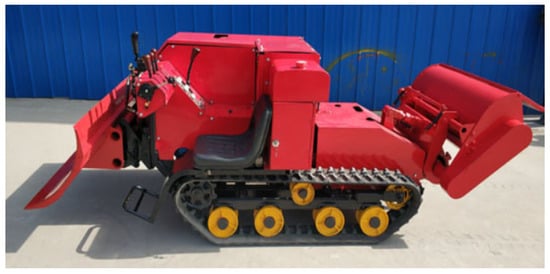
Figure 17.
Universal chassis prototype.
5.1. Hill-Climbing Performance Test
Climbing performance serves as a pivotal indicator of chassis power capability in orchard operations carried out in complex environments. As such, possessing excellent climbing performance is imperative to ensure optimal functionality. For the climbing performance test the slope of the prototype is set to 20°~35°, and the climbing process is divided into three stages, as illustrated in Figure 18. The machine assumes a stationary position on a horizontal road and engages the first gear to commence the climb. Throughout the test, the speed and progression of the machine are meticulously scrutinized and recorded. Qualifying criteria dictate that the machine must “pass”. Table 2 lists the recorded test data.

Figure 18.
Hill-climbing performance test: (a) the beginning of the climb; (b) climbing stage; (c) late climbing stage.

Table 2.
Test data.
The test results suggest that the designed longitudinal operating slope of the universal orchard chassis is able to smoothly pass within a slope range of 35°. However, during the final test, a slight deviation from the theoretical and simulated values is observed due to the test site’s hard soil surface.
5.2. Vertical Obstacle-Passing Test
The barrier-crossing process involves three stages, as illustrated in Figure 19. The test begins by engaging the first gear and driving the vehicle at a consistent speed directly toward vertical obstacles. The obstacles selected for testing vary in height, starting from low and gradually increasing in height until it becomes impossible for the vehicle to pass. The maximum height of the complete machine on flat ground that allows it to pass as qualified is recorded as the results, which are listed in Table 2.

Figure 19.
Obstacle-passing test: (a) before crossing the barrier; (b) obstacle crossing; (c) after crossing the obstacle.
Based on the vertical obstacle-passing test, it can be inferred that the maximum vertical barrier limit height of the chassis is 200 mm. The value obtained in the test is greater than that predicted by theoretical calculation and simulation. This phenomenon is attributed to the non-rigidity of the test site’s vertical barrier, which allows the barrier to deform and makes it easier for the chassis to cross. Consequently, the chassis can surpass the height of the barrier predicted by theoretical calculation and simulation.
5.3. Trench-Crossing Test
In accordance with the “Tractor Design Manual” for agricultural tractor passability testing, a chassis trench-crossing experiment is conducted on flat ground. A rectangular cross-section trench is set up in the test, with straight trench edges and the length of the trench not less than 1.5 times the width of the chassis body, as depicted in Figure 20. To initiate the trench-crossing test, the vehicle approaches the trench in first gear at a steady speed, starting from a narrow trench and gradually widening it until the chassis is unable to pass through. The maximum width of the trench that the chassis can successfully traverse on flat ground is determined and recorded as the test result. In Table 2, the recorded data indicate that the multifunctional universal chassis can cross trenches with widths up to 430 mm. The test value is slightly higher than the theoretical calculation and simulation values due to the non-inclusion of ground deformation in the theoretical calculation.

Figure 20.
Trench-crossing test: (a) phase I of crossing the trench; (b) phase II of crossing the trench; (c) phase III of crossing the trench.
6. Conclusions
(1) Through force analysis of a universal chassis operating in hilly mountainous orchards and overcoming typical challenged, such as climbing, crossing obstacles, and crossing trenches, a correlation between the passing performance and the structural parameters of the crawler chassis is established. According to the calculation, the maximum climbing degree is 35.8°, the maximum vertical height of crossing is 170.4 mm, and the maximum width of slope-free trenches that can be crossed is 427 mm. Using Matlab software, the relationship between each parameter and the passing performance evaluation index is analyzed through a surface diagram, revealing that the slope, the speed of obstacle crossing, and the position of the center of mass are the primary factors affecting the passing performance of the crawler-type hilly mountain transport vehicle.
(2) The passability of the universal chassis is simulated, and 3D models are created using SolidWorks and RecurDyn software. The resulting graphs are used to analyze the change processes of center-of-mass velocity, pitch angle, lateral tilt angle, longitudinal displacement, and offset of the entire vehicle in operation over time. The simulation demonstrates that the crawler chassis can cross a slope of up to 35°, vertical obstacles up to a height of 150 mm, and trenches with a width of up to 400 mm.
(3) To verify the accuracy of the theory and simulation, a passing performance test of the prototype is conducted at the designated test site, which includes climbing, obstacle passing, and trench-crossing tests. The test results reveal that the maximum limit slope for longitudinal climbing is 35°, the vertical barrier height for the obstacle-passing test is 200 mm (however, during the actual test, the front part of the track packs the obstacle, reducing the over-barrier height), and the maximum width of trench-crossing is 430 mm. The test results indicate reasonable errors compared to the theoretical and simulation values, thus demonstrating that the test can meet the necessary requirements of usage.
Author Contributions
Conceptualization, X.H. and X.M.; methodology, X.H. and F.W.; software, X.M., Y.Y. (Yijie Yue) and Q.L.; validation, C.H., X.H., Q.L. and G.M.; formal analysis, C.H.; investigation, X.M. and C.H.; Resources, Y.Y. (Yuanman Yue); writing—original draft preparation, X.M.; writing—review and editing, X.H. and X.M.; visualization, X.M.; supervision, X.H.; project administration, X.H. and F.W. All authors have read and agreed to the published version of the manuscript.
Funding
This research was supported by the Key R&D Program of Gansu Province in China (grant No. 21YF5NA093).
Institutional Review Board Statement
Not applicable.
Data Availability Statement
The data presented in this study are available upon request from the authors.
Acknowledgments
The authors thank the editor for providing helpful suggestions to improve the quality of this manuscript.
Conflicts of Interest
The authors declare no conflict of interest.
References
- The State Statistics Bureau. China Statistical Yearbook; China Statistics Press: Beijing, China, 2019.
- Ministry of Agriculture. The 13th Five-Year Plan for the Development of Agricultural Mechanization in China. China Agric. Mech. 2017, 01, 09. [Google Scholar]
- Li, H. Research and Prospect of crawler chassis of agricultural machinery in mountainous and hilly areas. In Proceedings of the 2021 1st International Conference on Control and Intelligent Robotics, Guangzhou, China, 18–20 June 2021; pp. 1–5. [Google Scholar]
- Sun, J.B.; Meng, C.; Zhang, Y.Z.; Chu, G.P.; Zhang, Y.J.; Yang, F.Z.; Liu, Z.J. Design and physical model experiment of an attitude adjustment device for a crawler tractor in hilly and mountainous regions. Inf. Process. Agric. 2020, 7, 466–478. [Google Scholar] [CrossRef]
- Tao, W.; Wu, H.B.; Liu, Q.T.; Liang, X.L.; Fan, Q.J.; Xie, C. Design and Development of Tracked Sugarcane Transporter. Sugar Tech. 2021, 23, 1137–1146. [Google Scholar]
- Mężyk, A.; Czapla, T.; Klein, W.; Mura, G. Numerical simulation of active track tensioning system for autonomous hybrid vehicle. Mech. Syst. Signal Process. 2017, 89, 108–118. [Google Scholar] [CrossRef]
- Lv, K.; Mu, X.; Li, L.; Xue, W.; Wang, Z.; Xu, L. Design and test methods of rubber-track conversion system. Proc. Inst. Mech. Eng. Part D J. Automob. Eng. 2019, 233, 1903–1929. [Google Scholar] [CrossRef]
- Chen, L.; Wang, P.; Zhang, P.; Zheng, Q.; He, J.; Wang, Q. Performance analysis and test of a maize inter-row self-propelled thermal fogger chassis. Int. J. Agric. Biol. Eng. 2018, 11, 100–107. [Google Scholar] [CrossRef]
- Sun, S.; Wu, J.; Ren, C.; Tang, H.; Chen, J.; Ma, W.; Chu, J. Chassis trafficability simulation and experiment of a LY1352JP forest tracked vehicle. J. For. Res. 2020, 32, 1315–1325. [Google Scholar] [CrossRef]
- Wang, Y.; Yang, F.; Pan, G.; Liu, H.; Liu, Z.; Zhang, J. Design and Testing of a Small Remote-Control Hillside Tractor. Trans. ASABE 2014, 57, 363–370. [Google Scholar]
- Zhao, H.; Wang, G.; Wang, H.; Bi, Q.; Li, X. Fatigue life analysis of crawler chain link of excavator. Eng. Fail. Anal. 2017, 79, 737–748. [Google Scholar] [CrossRef]
- Wang, P.; Mo, C.; Kim, S.; Han, X. Dynamics Simulation and Field Test Verification of Multi-Functional Beekeeping Loading Box Based on the Tracked Vehicle. Appl. Sci. 2022, 12, 6667. [Google Scholar] [CrossRef]
- Wu, Z.Y.; Gao, Y.D.; Xu, Z.; Wang, S.F. Modeling and Simulation of Tracked Vehicle Based on Pro/E and RecurDyn. In Proceedings of the 5th International Conference on Advanced Design and Manufacturing Engineering, Belgrade, Serbia, 5–9 June 2015; Atlantis: Paris, France, 2015; p. 10. [Google Scholar]
- Mudarisov, S.; Gainullin, I.; Gabitov, I.; Khasanov, E.E. Improvement of Traction Indicators of a Track-Chain Tractor. Communications. Sci. Lett. Univ. Zilina 2020, 3, 89–102. [Google Scholar]
- Hu, J.; Pan, J.; Dai, B.; Chai, X.; Sun, Y.; Xu, L. Development of an Attitude Adjustment Crawler Chassis for Combine Harvester and Experiment of Adaptive Leveling System. Agronomy 2022, 12, 717. [Google Scholar] [CrossRef]
- Yang, H.; Xia, C.; Han, J.; Chen, C.; Zhang, H. Model and dynamic performance analysis of mountain tractor suspension implements. In Proceedings of the 2020 6th International Conference on Energy Materials and Environment Engineering, Tianjin, China, 24–26 April 2020. [Google Scholar]
- Haun, R.D. Mower Deck Leveling System. U.S. Patent 20,150,296,711, 6 October 2015. [Google Scholar]
- Mikiya, S.; Kyukor. Crawler Type Traveling Device. Japan Patent No. JP4207856B2, 4 January 2009. [Google Scholar]
- Yukikazu, T. Posture Controlling Device for Combine Harvester. Japan Patent No. JP2013055897A, 7 September 2011. [Google Scholar]
- Shunki, K. Working Machine. Japan Patent No. JP5313516B2, 6 February 2008. [Google Scholar]
- Gonzalez, D.O.; Martin-Gorriz, B.; Berrocal, I.I.; Hernandez, B.M.; Garcia, F.C.; Sanchez, P.M. Development of an automatically deployable roll over protective structure for agricultural tractors based on hydraulic power: Prototype and first tests. Comput. Electron. Agric. 2016, 124, 46–54. [Google Scholar] [CrossRef]
- Ballesteros, T.; Arana, I.; Ezcurdia, A.P.; Alfaro, J.R. E2D ROPS: Development and tests of an automatically deployable, in height and width, front-mounted ROPS for narrow-track tractors. Biosyst. Eng. 2013, 116, 1–14. [Google Scholar] [CrossRef]
- Sun, Y.; Xu, L.; Jing, B.; Chai, X.; Li, Y. Development of a four-point adjustable lifting crawler chassis and experiments in a combine harvester. Comput. Electron. Agric. 2020, 173, 0168–1699. [Google Scholar] [CrossRef]
- Keller, T.; Arvidsson, J. A model for prediction of vertical stress distribution near the soil surface below rubber-tracked undercarriage systems fitted on agricultural vehicles. Soil Tillage Res. 2016, 155, 116–123. [Google Scholar] [CrossRef]
- Nicolini, A.; Mocera, F.; Soma, A. Multibody simulation of a tracked vehicle with deformable ground contact model. Intitution Mech. Eng. 2019, 233, 152–163. [Google Scholar] [CrossRef]
- Mocera, F.; Somà, A.; Nicolini, A. Grousers Effect in Tracked Vehicle Multibody Dynamics with Deformable Terrain Contact Model. Appl. Sci. 2020, 10, 6581. [Google Scholar] [CrossRef]
- Cui, Z.C.; Guan, C.S.; Chen, Y.S.; Gao, Q.S.; Yang, Y.T. Design of small multi-functional electric crawler platform for greenhouse. Trans. Chin. Soc. Agric. Eng. 2019, 35, 48–57. [Google Scholar]
- Bao, X.; Mao, J.; Dai, P.; Gong, Z.; Li, S.; Chen, H. Research on trajectory planning and control system of general mobile platform for Mountain Orchard. J. Eng. 2022, 36, 466–477. [Google Scholar] [CrossRef]
- Wang, F. Study on Slope Passability of the Orchard Power Chassis in Hilly Area. Master’s Thesis, Southwest University, El Paso, TX, USA, 2014. [Google Scholar]
- Zhang, X.Z.; Shen, R.F.; Wang, J.L. Obstacle Crossing Analysis of Transport Vehiclesin Mountain Orchard. J. Shandong Agric. Univ. (Nat. Sci. Ed.) 2020, 51, 482–486. [Google Scholar]
- Han, Z.; Zhu, L.; Yuan, Y.; Zhao, B.; Fang, X.F.; Zhang, T.F. Analysis of Slope Driving Performance and Optimized Design of Crawler Chassis in Hillside Orchard. Trans. Chin. Soc. Agric. Mach. 2022, 53, 413–421+448. [Google Scholar]
Disclaimer/Publisher’s Note: The statements, opinions and data contained in all publications are solely those of the individual author(s) and contributor(s) and not of MDPI and/or the editor(s). MDPI and/or the editor(s) disclaim responsibility for any injury to people or property resulting from any ideas, methods, instructions or products referred to in the content. |
© 2023 by the authors. Licensee MDPI, Basel, Switzerland. This article is an open access article distributed under the terms and conditions of the Creative Commons Attribution (CC BY) license (https://creativecommons.org/licenses/by/4.0/).