Abstract
In this study, a comb-type buckwheat-harvesting device was designed and tested for use in hilly areas and on small plots of buckwheat in China. The device uses semi-feeding and allows for threshing before cutting. Through the parametric design of the threshing mechanism, a dynamic model of the comb teeth’s striking of buckwheat plants was established. The effect of the machine’s forward speed and the speed of the comb teeth on the threshing rate was explored via a single-factor experiment. Based on the simulation test and actual operations, an orthogonal experiment with three factors and three levels was performed, using the machine’s forward speed, the speed of the comb teeth, and the tilt angle of the threshing mechanism as the factors, and the threshing rate, breakage rate, and loss rate as the indicators. Regression equation models were established for the relationship between the influencing factors and the threshing rate, breakage rate, and loss rate, and a response surface analysis of the influencing factors and their interaction was carried out. The results showed that the speed of the comb tooth had the greatest influence on the threshing rate, breakage rate, and loss rate, followed by the machine forward speed; the tilt angle of the threshing mechanism had the least influence on the threshing rate, breakage rate, and loss rate. By optimizing the multi-objective parameters of the regression equation models, reasonable parameters were obtained for the influencing factors: the machine forward speed was 0.5 m/s, the speed of the comb teeth was 1.2 m/s, and the inclination of the threshing mechanism was 45°. Under these conditions, the threshing rate was 80.10%, the breakage rate was 1.83%, and the loss rate was 7.03%.
1. Introduction
Buckwheat is widely used as a multi-grain cash crop for its exceptional nutritional composition [1], high medicinal value, and outstanding health-giving properties. As living standards have improved, people have progressively developed a more in-depth awareness of dietary nutrition and health [2,3,4], such that the demand for buckwheat in the domestic and foreign markets has risen dramatically. China is a major producer of buckwheat, with its buckwheat output and planting area ranking second in the world. As buckwheat plants grow, their stems bifurcate, and the flowers, fruit, and branches intertwine, pulling continuously on one another [5]. Moreover, buckwheat exhibits a high stem-to-grain ratio, which is inconsistent with plant grain maturity; mature grains fall off easily and the stems have high moisture content at the time of harvest. Most buckwheat in China is planted in arid regions, on hilly mountains and gentle slopes, which is highly significant for optimizing the production potential of low-quality land. Buckwheat is difficult to harvest mechanically due to its material characteristics at harvest time. The existing buckwheat-harvesting machinery exhibits various problems, including serious threshing loss, threshing drums that plug easily, high impurity rates, and poor operations. It is difficult to meet the demands of buckwheat harvesting in China. At the same time, compared with wheat, rice, corn, and other staple crops, buckwheat is a crop produced in relatively small quantities, and, as a result, the development of buckwheat-harvesting machinery is remarkably slow [6].
Most buckwheat combine harvesters are improved based on other crop harvesters, such as those used for rice and wheat. For instance, Straksas et al. of Lithuania used the SR500 combine harvester, produced by Sampo Rosenlew of Finland, to harvest buckwheat. The results illustrated that the grain loss rate was three times lower than that of the traditional one-time combine harvester, and the machine is therefore more suitable for buckwheat harvesting [7]. However, this machine is not suitable for the hilly terrain and small plots used to grow buckwheat in China. In order to accelerate the mechanization of buckwheat harvesting in China, a buckwheat combine harvester test was carried out. After the improvement of the self-propelled tracked grain combine harvesters 4LZ-1.6 and 4LZ-1.8, obtained from the Southern Machinery Co., Ltd., the results showed that the machine causes leakage when cutting and is poorly adapted for use in hilly and mountainous areas. This accounts for why it has not been popularized [6]. Intending to solve the problem of the existing combine grain harvesting equipment being poorly suited to the harvest characteristics of buckwheat, Meng Yi et al. designed a kind of stripping apparatus with air suction for harvesting buckwheat. They obtained the best parameter combination for the feeding speed, feeding wind pressure, and roller speed, and also carried out bench tests, but no verification was performed with a real machine [8]. In order to better understand the background conditions and shortage of buckwheat-harvesting devices at home and abroad, the details are listed in Table 1.

Table 1.
Advantages and disadvantages of different kinds of buckwheat-harvesting devices.
To address the above problems, based on buckwheat’s material features and using the harvest method of threshing before cutting, this paper developed a comb-type buckwheat-harvesting device suitable for application to Chinese small plots in the strip-planting style. The key component of the threshing mechanism was designed via parameterization. The operation parameters were simulated and analyzed via ADMAS. A test was carried out in a field experiment, and the device solved the problems of the grain loss rate, the breakage rate, and the plugging of machinery that are encountered in one-time buckwheat combine harvesters.
2. The Structure and Working Principle of the Whole Machine
The comb-type buckwheat-harvesting device mainly comprises a threshing mechanism, a grain collection mechanism, a profiling mechanism, a feeding mechanism, etc. Its overall structure is shown in Figure 1. The threshing mechanism is the core of the comb-type buckwheat-harvesting device; it is located at the center of the device at a certain tilt angle. Its function is to thresh buckwheat plants. This process is complicated. Specifically, the flexible comb tooth is the core of the threshing mechanism; the flexible comb tooth rotates and hits and brushes buckwheat plants with the machine facing forward. The grain collection mechanism is located directly below the threshing mechanism, and it is used to collect and store the buckwheat grains that have fallen from buckwheat plants due to the striking of the threshing mechanism. The profiling mechanism is situated directly in front of the threshing mechanism, the height of which can be adjusted to meet the demands of different terrain types. The feeding mechanism is situated on the lower right of the threshing mechanism and its function is to feed the buckwheat into the threshing mechanism. The press plate is used to bend the buckwheat and is convenient for hitting and brushing the threshing mechanism.
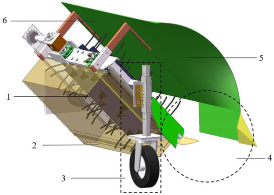
Figure 1.
Structure of a comb-type buckwheat-harvesting device. 1—threshing mechanism; 2—grain collection mechanism; 3—profiling mechanism; 4—feeding mechanism; 5—curved plate; 6—press plate.
The comb-type buckwheat-harvesting device harvests mature buckwheat; this process is divided into three work steps, including plant feeding, plant bending, and plant threshing (Figure 2). The comb-type buckwheat-harvesting device is placed in front of the power machine during operation. When harvesting buckwheat, the power machine provides the power both before and during the running of the harvesting device. The buckwheat plant is divided and fed into the curved plate. As shown in Figure 2a, with the machine moving forward in a direction that is perpendicular to the page and outward, a row of buckwheat plants is divided from a larger section of buckwheat plants by the crop divider of the feeding mechanism. Divided buckwheat plants are bent to a certain angle by the curved plate so that the buckwheat plants maintain a certain angle when moving into the threshing mechanism. As shown in Figure 2b, as the machine moves further forward, the buckwheat plants are pressed at a certain angle and cling to the press plate, and the flexible comb tooth strikes, hits, and brushes the buckwheat plants from front to back. As shown in Figure 2c, because buckwheat grains are threshed easily by being hit with the flexible comb tooth, the binding force between the buckwheat grains and the stalk is overcome, and the buckwheat grains fall. After threshing, the machine moves forward, the buckwheat stalks are excluded from the threshing mechanism and remain on the ground, most of the buckwheat grains fall into the material collection box at the hollow of the threshing mechanism, and a small portion of the grains fall to the grain board under the action of gravity. At this point, the threshing process is complete.
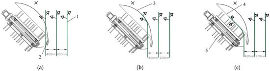
Figure 2.
The working process of the comb-type buckwheat-harvesting device. (a) The feeding of the buckwheat plant. (b) The bending of the buckwheat plant. (c) The threshing of the buckwheat plant. 1—buckwheat; 2—crop divider; 3—curved plate; 4—press plate; 5—flexible comb tooth.
3. Key Component Design and Parameter Determination
3.1. The Design of the Threshing Mechanism
The threshing mechanism is the core component of the comb-type buckwheat-harvesting device (Figure 3), which mainly comprises a threshing shaft, a fixing rod, a side plate, a flexible comb tooth, a sprocket, a support shaft, and a chain. The buckwheat harvest is directly affected by the parameters and structure of the threshing elements, the size of the overall threshing parameters, and so on. In order to reduce the impact on the buckwheat grains, flexible materials are chosen for the threshing components in order to reduce the breakage rate of buckwheat grains. The flexible comb tooth is fixed on the fixing rod, and the fixing rod is connected to the threshing chain by the chain drive mode. With the input of power, the flexible comb tooth rotates with the rotation of the chain, the flexible comb tooth hits the stalk of buckwheat, and the grains fall off [9,10,11,12,13].
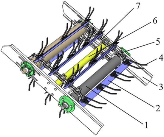
Figure 3.
The structure of the threshing mechanism. 1—threshing shaft; 2—fixing rod; 3—size plate; 4—flexible comb tooth; 5—sprocket; 6—support plate; 7—chain.
3.1.1. Length of the Threshing Mechanism L
When the comb-type buckwheat-harvesting device is in operation, the buckwheat plants are tilted to a certain angle to comb and threshed. Therefore, the length parameter of the threshing mechanism should be determined according to the lowest scion height and buckwheat plant height, and its length L is:
where L is the length of the threshing mechanism, L1 is the height of the buckwheat plant (the height of “Xinong9979” is 590–920 mm), and L2 is the minimum height of the buckwheat ears (the lowest spike height of “Xinong9979” is 220–450 mm).
The threshing mechanism has the function of combing from front to back. In order to ensure that all the parts of buckwheat plants containing grain can be hit by the threshing mechanism, the length of the threshing mechanism is initially selected as 650 mm.
3.1.2. Width of the Threshing Mechanism D
The width of the threshing mechanism determines the duration of the buckwheat threshing process. Buckwheat plants need to be threshed and discharged under the comb tooth of the threshing mechanism. If the threshing mechanism is too wide, the plants in the device cannot be discharged in time, leading to blockages in the threshing mechanism when buckwheat plants are pulled out. If the threshing mechanism is too narrow, the buckwheat grains may not be threshed completely. Its width D is:
where D is the width of the threshing mechanism.
Based on the above parameters, the threshing mechanism’s width is initially selected to be 350 mm.
3.1.3. Design and Material Selection of the Flexible Comb Tooth
(1) The length of the flexible comb tooth l
The flexible comb tooth is the threshing element that directly hits the stalks and grains of buckwheat, the length of which must be sufficient to hit all of the buckwheat plant. Its length is:
where l is the length of the flexible comb tooth, Vm is the machine’s forward speed, B is the working width of the machine, K is the buckwheat stalk accumulation coefficient, and vs. is the speed of the top of the comb tooth.
As the comb-type buckwheat-harvesting device adopts a semi-feeding design, the forward speed of the semi-feeding machine is generally 1–3 km/h. The forward speed of the comb-type buckwheat-harvesting device is set at 3 km/h. The working width of the machine is 420 mm. The buckwheat stalk accumulation coefficient is 2.9. The speed of the comb tooth top is taken as 8.5 m/s. By substituting the above values into Equation (3), the minimum length of the tooth of the flexible comb is 158 mm. In order to ensure that the comb tooth hits all of the buckwheat plants, we selected 160mm as the length of flexible comb tooth l.
As shown in Figure 4, the flexible comb tooth consists of the main body of the flexible comb tooth and the soleplate. The soleplate is installed on the fixing rod. In order to better achieve the flexible comb tooth’s hitting effect, the main body of flexible comb tooth is bent to 160°.
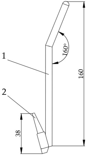
Figure 4.
The structure of the flexible comb tooth. 1—the main body of the flexible comb tooth; 2—the soleplate.
(2) The material of the flexible comb tooth
Considering cost, wear resistance, and interchangeability, the flexible comb tooth is made of nylon.
3.1.4. Number of Rows of the Flexible Comb Tooth n
Buckwheat is threshed by the hitting and combing of the flexible comb tooth, so the number of rows of the comb tooth directly affects the threshing effect. In the case of a fixed feeding amount, the more lines the flexible comb tooth has, the fewer plants each line of comb teeth will be “responsible” for, improving the threshing effect. However, too many rows of comb teeth can cause motion interference. In this paper, ADAMS software is used to carry out kinematic simulations of different numbers of rows of comb teeth, and a reasonable number of comb tooth rows is confirmed by the simulation experiment. The experimental results are presented in Figure 5.
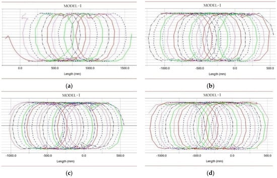
Figure 5.
Trajectory of the comb tooth top. (a) The track of five rows of comb teeth. (b) The track of six rows of comb teeth. (c) The track of seven rows of comb teeth. (d) The track of eight rows of comb teeth.
It can be determined from Figure 5 that, when the forward speed and threshing speed are constant, the more rows of comb teeth there are, the more the trajectory of the tooth end of the comb tooth tends to a smooth straight line, and the smaller the leakage cut zone is, and the better the threshing effect will be. However, when the number of rows of comb teeth is eight, the movement of the end of the comb is usually staggered, because the row spacing is too small, leading to interference with the motion of the two rows of teeth. Adjacent rows of comb teeth “fight”, leading to a threshing impact on the buckwheat plants. This results in grains being violently slashed, which is not conducive to the collection of buckwheat grains. Therefore, in this design, the threshing mechanism has seven rows of comb teeth.
3.2. Dynamic Analysis of Combing Process
Buckwheat stalks are hit and disturbed by the flexible comb tooth, so that buckwheat grains are threshed. The stress model of the stem in threshing process was established. The part of the buckwheat stem that is in contact with the tooth of the flexible comb is regarded as a rigid body. Assuming that, when the comb tooth comes into contact with the buckwheat, the center of gravity of the buckwheat stem is located at point B, then the buckwheat stem stress force is shown in Figure 6. In this case, the resultant vector F of the buckwheat stem is:
where F denotes the external forces acting on the stem of the buckwheat, Ff is the friction between the stem and the comb tooth, Ft is the pulling force between the contact stem and the other stem, and FN is the force of the flexible comb tooth on the buckwheat stem.
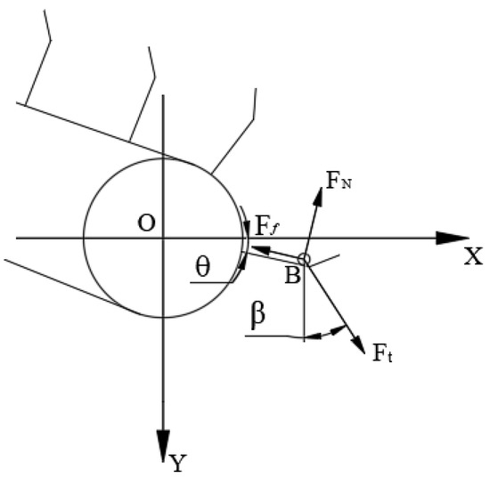
Figure 6.
Stress analysis of the buckwheat stem.
3.3. Analysis of the Buckwheat Threshing Simulation Process
As the process of buckwheat threshing is highly complicated and difficult to monitor, it is impossible to obtain detailed analyses of the force and motion parameters acting between the stem and working parts during the threshing process. To analyze the process whereby the threshing mechanism hits the stalk of buckwheat, which resultx in the shedding of buckwheat grains, ADAMS and ANSYS were used in this paper to establish a rigid–flexible mixed model of buckwheat (stem–fruit and stalk–grain), and a kinematic and dynamic simulation of the buckwheat threshing process was performed to obtain the kinematic parameters of buckwheat grains in the shedding process. It provides a reference for the selection of test factors and parameters of the prototype threshing mechanism.
The ADAMS multi-body dynamics simulation software comprises two ways to establishing the flexible body model. One is a flexible beam connection, which works to discretize a section of the rigid body into a flexible beam connection of a multi-end rigid body; its nature is not that of a real flexible body. The other is the neutral mode file method of the mode superposition theory, which uses its ADAMS/ViewFlex module or third-party finite element software, such as ANSYS/APDL, to create a modal neutral file (MNF) in order to replace the original rigid body [14]. The modal file is capable of accurately indicating the ground deformation of the flexible body in dynamic analysis. Since the flexible body module of ADAMS cannot achieve the expected effect on the parts with complex shapes, this is used to simulate the rigid–flexible mixed model of buckwheat stem–fruit and stalk–grain more accurately. In this study, ADAMS and ANSYS/APDL co-simulation was adopted, the buckwheat plant model was divided by ANSYS/APDL using meshes, and flexible processing (e.g., nodes and rigid areas) was established [15]. MNF of buckwheat stems were generated and then imported into ADAMS [16].
3.3.1. Establishment of the Rigid–Flexible Mixed Model of Buckwheat (Stem–Fruit and Stalk–Grain)
Given the complex structure of the buckwheat stem–fruit and stalk–grain model and the weak ADAMS modeling function, professional CAD software SOLIDWORKS was adopted to establish its model. An X_T format file was created and imported into ADAMS. Using the method of neutral modal file, the fruit stem was discretized into a fine grid using ANSYS/APDL, and the nodes and rigid areas were set to facilitate the connection of rigid grains and flexible fruit stalks with flexible stems. Subsequently, CB modal calculation was performed, and the calculated modal file was saved as MNF, which was directly read into ADAMS. The stem was flexible, and the grain and the fruit stalk remained rigid. The modeling is illustrated in Figure 7.
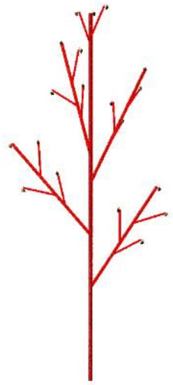
Figure 7.
The rigid–flexible mixed model of buckwheat (stem–fruit and stalk–grain).
3.3.2. Defining the Key Technologies That Drive Constraints and Processes
(1) Buckwheat threshing control
The most critical technology in this model refers to achieving multiple independent control processes for buckwheat-grain-shedding simulation. In ADAMS, most of the control entities and the separation between entities use scripted controls to make the connection force relationship fail; the limitation of the method is that it cannot control the shedding of multiple independent individuals. Thus, generalized force and sensor function controls were adopted in this study, with the aim of achieving the independent control of multiple buckwheat grains. Specifically, the buckwheat grains and the stalk between the connection method use a generalized force connection [17,18,19,20,21,22,23,24,25,26]. Here, the generalized force is composed of a three-part moment and a three-part force (Figure 8).
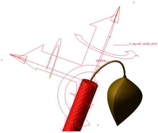
Figure 8.
The establishment of a generalized three-point force.
(2) Defining the key techniques for constraint drivers and processes
The magnitude of the generalized force serves as the connection force between the buckwheat kernels and the stalk by helping to detect the change in the generalized force between the buckwheat kernels and the stalk at the two connection points. Sensors were used to monitor whether the generalized force reached the minimum value required for threshing. When the generalized force reached the value required for threshing, the force of the connection between the buckwheat grain and the stalk was revealed to be 0. The buckwheat grain moisture content was examined by using the tensile testing machine for harvesting and found to be 9.83%, and the connection between the grain and the stalk exhibited a force of 0.65 N. The connection force stiffness K was 180 N/m, and the damping factor C served as the default value. The generalized force in Fx was obtained as a function of:
where SENVAL() is the function used to return the sensor value; SENVOR_1 is the sensor that measures the distance between the two action points of the generalized force; K is the stiffness coefficient; grain_center is the grain attachment point; and stalk_center is the fruit stalk attachment point. In the generalized force, the other component force and moment functions are used as such.
Using the impact function method to define the contact force between the buckwheat stalk and the comb tooth, the contact type is a rigid body and a flexible body, K takes the value of 5930 N/m, and C takes the default value. The buckwheat stalk is fixed on the ground, the threshing mechanism establishes a translation with the ground, defining the translational force, and the threshing mechanism’s threshing shaft defines the rotational force (Figure 9). A picture of the intermediate changes that occur during the simulation process is illustrated in Figure 10.
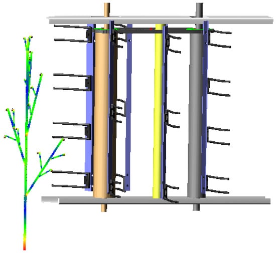
Figure 9.
The contact model between the threshing mechanism and the buckwheat.
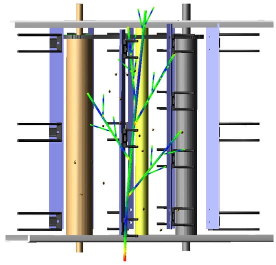
Figure 10.
Picture of intermediate changes during the simulation process.
3.3.3. Grain Drop Simulation Test and Analysis of Results
In this study, 19 buckwheat grains were set at the top of the buckwheat stalk, the time of the simulation was set to 10 s, the step size was 500 steps, and the simulation solver was set to be a WSTIFF solver. Compared with the GSTIFF solver, this solver is more robust and stable, whereas the simulation time was longer than that of the GSTIFF solver. The integration format was set to SI1 and the error was set to 1 × 10⁻³, where the dropped grains were noted and their number was recorded as m. The total number of grains is expressed as M. Consequently, the grain loss rate is expressed as:
where Y is the threshing rate, m is the number of dropped seeds, and M expresses the total number of grains.
(1) Effect of the threshing mechanism’s forward speed on the threshing rate
As shown in Figure 11a, with the increase in the threshing mechanism’s forward speed (the speed of the comb tooth’s top is 1.1 m/s), the threshing rate of the buckwheat grains decreases. This is because, when the threshing speed is unchanged and the threshing mechanism’s speed increases, the number of comb teeth that hit the buckwheat stalk within a given time interval is reduced, resulting in the buckwheat threshing rate being reduced. By reducing the ratio between the circumferential linear speed of the comb tooth VB and the forward speed of the threshing mechanism Vm, that is, the threshing speed ratio λ, the threshing rate also decreases. In the early stage of threshing, most of the buckwheat grains fell off due to the impact force of the comb tooth coming into contact with the stalk model of the buckwheat, but the buckwheat grains that were far away from the comb tooth were not subjected to enough force to make them fall off, meaning that some buckwheat grains did not fall off. Therefore, in the prototype test, it is necessary to analyze this factor and select the best value for the machine forward speed.
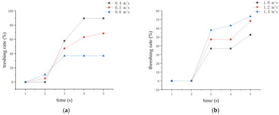
Figure 11.
Effect of various factors on the threshing rate. (a) Effect of the forward speed of the threshing mechanism on the threshing rate. (b) Effect of the speed of the comb tooth top on the threshing rate.
(2) Effect of the speed of the comb tooth top on the threshing rate.
As demonstrated in Figure 11b, with the increase in the speed of the comb tooth (when the threshing mechanism’s forward speed is 0.5 m/s), the threshing rate of the buckwheat grain increases. This is because, as the speed of the comb tooth increases, the impact force also increases; the impulses received by the buckwheat grain increase, and the buckwheat grains more easily fall off. At the same time, the number of comb tooths of the threshing mechanism that hit the buckwheat model also increase. Therefore, in the prototype test, it is necessary to analyze this factor and select the best linear speed for the threshing mechanism.
4. Field Experiments and Analysis of Results
4.1. Experiment Equipment and Materials
The field experiment was performed on 11 July 2022 in the test field of the Northwest Agriculture and Forestry University of Science and Technology North Campus, Yangling District, Xianyang City, Shaanxi Province. The object of this study was “Xinong9979”, and its grain maturity was 70%. The moisture content of the buckwheat stems and buckwheat grains was deemed to be 68.5% and 15.4%, respectively, according to Ohaus moisture tester results on the day of the experiment. The experimental equipment used included the comb-type buckwheat-harvesting device made by Northwest A & F University, as shown in Figure 12.
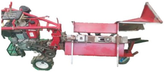
Figure 12.
Prototype of the comb-type buckwheat-harvesting device.
4.2. Factor Selection for the Experiment
In order to achieve the required threshing rate and control the loss rate and breakage rate, buckwheat threshing was performed as far down the buckwheat stalk grain as possible. Therefore, in the experiment, the threshing rate, breakage rate, and the loss rate of buckwheat grains were the main indicators. According to the preliminary simulation experiment and theoretical analysis, the main factors affecting the threshing effect of buckwheat were obtained from the speed of the comb tooth and the machine forward speed. In addition, the tilt angle of the threshing mechanism also had a certain effect on the threshing process. The tilt angle of threshing mechanism was designed to be adjusted from 35° to 65°. Because the threshing mechanism had a small inclination, the threshing mechanism could not thresh buckwheat grains normally. Likewise, when the threshing mechanism had a large inclination, the grain collection mechanism could not collect buckwheat grains normally. Therefore, the levels chosen for the tilt angle of the threshing mechanism were 35°, 50°, and 65° (Figure 13). The machine forward speed X1, the speed of the comb tooth X2, and the tilt angle of the threshing mechanism X3 were taken as the test factors, as shown in Table 2.
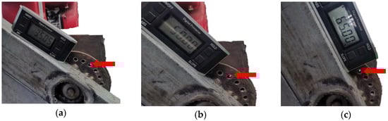
Figure 13.
Tilt angle of the comb-type buckwheat-harvesting device. (a) The tilt angle is 35°. (b) The tilt angle is 50°. (c) The tilt angle is 65°.
Table 2.
Coding of factors and levels.
4.3. Experimental Program
The field used for the harvesting experiment was divided into several sections, and the length of the buckwheat plants harvested in each group was 15 m. Natural shattering losses were collected in the field prior to the experiment. The dropped grains were collected from the ground in a 1 m length test row of the experimental buckwheat field. After the experiment, the buckwheat grains in the material collection box and the grain receiving board in the harvest prototype were collected and weighed, and the values were recorded as m1. A range of 1 m in the length of the test line was selected to collect the fallen grains within the range, and the weight of naturally falling grains was subtracted after weighing, with the value denoted as m2. Buckwheat plants 1 m in length after harvest were selected, and the grains from the plants were collected, weighed, and recorded as m3. The crushed grains produced in the material collection box and grain receiving board were recorded by weight as m4. The parameters of each group were tested three times, and the evaluation indexes of the experimental results were the threshing rate, breakage rate, and loss rate.
Evaluation index:
4.4. Field Test and Analysis of Results
A field orthogonal test of the comb-type buckwheat-harvesting device was performed in the experimental field in Yangling District, Xianyang City, Shaanxi Province, on 19 July 2022. The shape of the experimental field is a rectangle with a plot length of 120 m and a plot width of 31 m. It has an area of 3720 m2. The topography of the experimental field is low in the east and high in the west, with a slope of about 3.2°. The soil type in the experimental plots is brown soil. The density of the experimental plot’s soil is 1.210 g/cm3, the soil water content is 12.25%, and the soil compaction is 264.63 Kpa at 50 mm underground. The field orthogonal test site is shown in Figure 14. The person conducting the experiment controls the walking tractor and the direction in which the machine moves forward. As the walking tractor drives the comb-type buckwheat-harvesting device forward, the buckwheat plant is fed into the threshing mechanism via the feeding mechanism to conduct grain threshing.
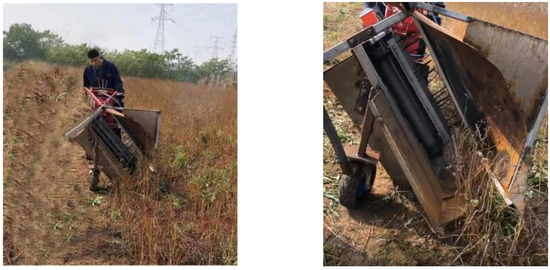
Figure 14.
Field experiment with the comb-type buckwheat-harvesting prototype.
The machine’s forward speed X1, the speed of the comb tooth X2, and the tilt angle of the threshing mechanism X3 were taken as the experimental factors, and the threshing rate Yt, the breakage rate Yb, and the loss rate Yl were taken as the evaluation indicators of the experiment. The test was conducted using the three-factor, three-level response surface method.
Response surface analysis tests of 17 groups were carried out (Table 3), and each group of tests was repeated three times.
Table 3.
Experimental method and results of the orthogonal rotational experiment.
4.5. Development and Testing of Regression Models for the Threshing Rate, Breakage Rate, and Loss Rate
(1) Development and testing of regression models for the threshing rate
The experimental results were analyzed using Design Expert software, and the quadratic regression equation model of the threshing rate Yt was developed with X1, X2, and X3 as the independent variables. The significance of the regression equation model was verified through an analysis of variance and an assessment of the regression coefficients. The results are given in Table 4.
Table 4.
Regression equation variance analysis of the threshing rate response surface.
According to Table 4, the regression equation for the threshing rate Yt, expressed via the coded values, was obtained by excluding the insignificant term in the regression equation:
The interaction between the other two factors and their effect on the threshing rate Yt was analyzed by fitting the response surface by setting any factor in Equation (10) to zero, as shown in Figure 15.
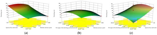
Figure 15.
Effects of the interaction of factors on the threshing rate. (a) Effect of the machine’s forward speed and the speed the of the comb tooth on the threshing rate. (b) Effect of the machine’s forward speed and the tilt angle of the threshing mechanism on the threshing rate. (c) Effect of the speed of the comb tooth and the tilt angle of the threshing mechanism on the threshing rate.
As shown in Figure 15a, there is no significant interaction between the forward speed of the machine and the speed of the comb tooth, which is consistent with the results of the analysis of variance. As the speed of the comb tooth increases, the threshing rate also increases. This is because, when the speed of the comb tooth increases, the comb tooth hits the buckwheat plant harder, resulting in a higher threshing rate. Similarly, the speed of the comb tooth increases, and the number of blows to the buckwheat plants increases within a given unit time, resulting in an increase in the threshing rate. As the forward speed of the machine increases, the threshing rate decreases slightly, and the forward speed of the machine has little effect on the threshing rate, which is consistent with the analysis of variance. As shown by Figure 15b, the interaction between the forward speed of the machine and the tilt angle of the threshing mechanism is not significant, which is consistent with the results of the variance analysis. As the forward speed of the machine has little influence on the threshing rate, the threshing rate decreases within a small range. With the increase in the tilt angle of threshing mechanism, the depuration first increases and then decreases. This is also consistent with the analysis of variance results, but has little effect on the depuration rate. When the tilt angle of the threshing mechanism is 47–53°, the threshing rate shows its minimum value. As shown in Figure 15c, the interaction between the speed of the comb tooth and the tilt angle of the threshing mechanism is not significant, which is consistent with the results of the variance analysis. The speed of the comb tooth has a significant influence on the threshing rate, which increases with the increase in the speed of the comb tooth. The speed of the comb tooth has the greatest influence on the threshing rate, followed by the forward speed of the machine, and the tilt angle of the threshing mechanism has the least influence on the threshing rate.
(2) Development and testing of regression models for the breakage rate
In the same situation as described above, the experimental results were analyzed, and the quadratic regression equation model of the breakage rate Yb was developed, with X1, X2, and X3 as the independent variables. The significance of the regression equation model was verified through an analysis of variance and a test of the regression coefficients. The results are listed in Table 5.
Table 5.
Regression equation variance analysis of the broken rate response surface.
According to Table 5, the regression equation for the breakage rate Yb, expressed by the coded values, was obtained by excluding the insignificant term in the regression equation:
The interaction between the other two factors and their effect on the breakage rate Yb was analyzed by fitting the response surface by setting any factor in Equation (11) to zero, as shown in Figure 16.
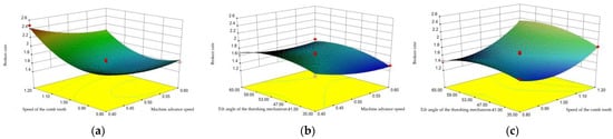
Figure 16.
Effects of the interaction of factors on the breakage rate. (a) Effect of the machine forward speed and the speed the comb tooth on the breakage rate. (b) Effect of the machine forward speed and the tilt angle of the threshing mechanism on the breakage rate. (c) Effect of the speed of the comb tooth and the tilt angle of the threshing mechanism on the breakage rate.
As shown in Figure 16a, the interaction between the forward speed of the machine and the speed of the comb tooth is not significant. The impact of the forward speed of the machine on the breakage rate is highly significant. With the increase in the forward speed of the machine, the breakage rate first decreases and then increases. Minimum values appear in the range of 0.5–0.6 m/s. Similarly, the speed of the comb tooth has a significant effect on the breakage rate. With the increase in the speed of the comb tooth, the breakage decreases first and then increases, and the minimum value appears to be near 9 m/s. Figure 16b shows that the interaction between the forward speed of the machine and the tilt angle of the threshing mechanism is not significant. The tilt angle of the threshing mechanism has no significant effect on the breakage rate. The breakage rate increases first and then decreases with the tilt angle of the threshing mechanism. Figure 16c shows that the interaction between the speed of the comb tooth and the tilt angle of the threshing mechanism is significant. The speed of the comb tooth has a significant effect on the breakage rate, while the angle of the threshing mechanism has no significant effect on the breakage rate, which is consistent with the results of the variance analysis. The speed of the comb tooth has the most significant influence on the breakage rate, followed by the forward speed of the machine, and the angle of threshing mechanism has the least influence on the breakage rate.
(3) Development and testing of regression models for the loss rate
In the same context as described above, the experimental results were analyzed using Design Expert software, and the quadratic regression equation model of the threshing rate Yt was developed, with X1, X2, and X3 as the independent variables. The significance of the regression equation model was verified through an analysis of variance and a test of the regression coefficients. The results are listed in Table 6.
Table 6.
Regression equation variance analysis of the loss rate response surface.
According to Table 5, the regression equation for the loss rate Yl, expressed by the coded values, was obtained by excluding the insignificant term in the regression equation:
The interaction between the other two factors and their effect on the loss rate Y was analyzed by fitting the response surface by setting any factor in Equation (12) to the zero level, as shown in Figure 17.
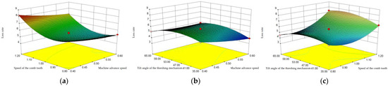
Figure 17.
Effects of the interaction of factors on the loss rate. (a) The effect of the machine’s forward speed and the speed the comb tooth on the loss rate. (b) The effect of the machine’s forward speed and the tilt angle of the threshing mechanism on the loss rate. (c) The effect of the speed of the comb tooth and the tilt angle of the threshing mechanism on the loss rate.
As shown in Figure 17a, there is no significant interaction between the machine’s forward speed and the speed of the comb tooth, which is consistent with the results of the variance analysis and regression analysis. Figure 17b shows that the forward speed of the machine has a significant interaction with the tilt angle of the threshing mechanism. The forward speed of the machine has a significant effect on the loss rate. As the forward speed of the machine increases, the breakage rate decreases. The tilt angle of threshing mechanism has no significant effect on the loss rate. The loss rate increases first and then decreases with the increase in the tilting angle of the threshing mechanism. As shown in Figure 17c, the interaction between the speed of the comb tooth and the tilt angle of the threshing mechanism is highly significant. The influence of the comb tooth on the loss rate is very significant. With the increase in the speed of the comb tooth, the loss first decreases and then increases, and the minimum value appears in the range of 0.8–1.0 m/s. The speed of the comb tooth has the greatest influence on the loss rate, followed by the forward speed of the machine, and the tilt angle of the threshing mechanism has the least influence on the loss rate.
4.6. Parameter Optimization and Experiments with a Comb-Type Buckwheat-Harvesting Device
The effect of the three test factors on the grain loss rate is ordered as follows: the speed of the comb tooth (X2), the machine’s forward speed (X1), and the tilt angle of the threshing mechanism (X3). To further determine the price of the comb-type buckwheat-harvesting device in order to determine the appropriate combination of parameters, we used a regression equation model for multi-objective parameter optimization. With the range of values of the test influence factors as the boundary conditions and the maximum threshing rate, the minimum breakage rate, and the minimum loss rate as the optimization objectives, the mathematical model was established as follows:
A Design Expert 8.0.61 software regression equation model for multi-objective optimal solutions was used to obtain the best test impact factor parameters: X2 was 1.16 m/s, X1 was 0.54 m/s, and X3 was 45.31°. In the optimal combination of parameters, the threshing rate Yt was 81.03%, the breakage Yb rate was 1.88%, and the loss rate Yl was 6.49%.
In accordance with the results of the multi-objective optimal solution, combined with the practical operating demands of the comb-type buckwheat-harvesting device, the test factor parameters are presented as follows: a machine forward speed of 0.5 m/s, a speed of the comb tooth of 1.2 m/s, and a tilt angle of the threshing mechanism of 45°. Under the conditions of the test factors affecting the parameters, three experiments were conducted. The test results are presented in Table 7. The threshing rate was 80.10%, the breakage rate was 1.83%, and the loss rate was 7.03%.
Table 7.
Experiment results of the optimal parameters test.
5. Conclusions
To meet the demands of the planting mode of buckwheat in hilly areas and small plots in China, a comb-brush-type buckwheat-harvesting device was designed. The device is a half-feeding type, uses the threshing-before-cutting method, and can effectively harvest buckwheat planted in hills and small areas.
The threshing mechanism of the key parts was designed by parameterization, and a dynamic model of how the comb tooth strikes buckwheat plants was established. Due to the complexity of the process of threshing buckwheat using a threshing mechanism, a collision simulation model of the comb-brush buckwheat-harvesting device and flexible buckwheat was established using ADAMS and ANSYS. The generalized force was used to establish the connection between the grain and the flexible stalk, and the sensor was used to detect the shedding condition of the grain to realize the shedding process of buckwheat grains under the action of external forces. According to the single factor test, the influence of the machine’s forward speed and the speed of the comb tooth on the threshing rate was explored. The test results showed that, when the machine’s forward speed was constant, the threshing rate increased with the increase in the speed of the comb tooth. When the speed of the comb tooth was fixed, the threshing rate decreased with the increase in the machine’s forward speed.
Based on the simulation test and on the actual operations, an orthogonal test of three factors and three levels was carried out with the machine’s forward speed, the speed of the comb tooth, and the tilt angle of the threshing mechanism as the factors, and the threshing rate, the breakage rate, and the loss rate as the indicators. A regression equation model was established to determine the relationship between the influencing factors and the threshing rate, the breakage rate, and the loss rate, and a response surface analysis of the influencing factors and their interaction was carried out. The results showed that the speed of the comb tooth had the greatest influence on the threshing rate, the breakage rate, and the loss rate, followed by the machine’s forward speed, and the angle of the threshing mechanism had the least influence on the threshing rate, the breakage rate, and the loss rate. By optimizing the multi-objective parameters of the regression equation model, the reasonable parameters of influencing factors were obtained: the machine forward speed was 0.5 m/s, the speed of the comb tooth was 1.2 m/s, and the inclination of the threshing mechanism was 45°. Under these conditions, the threshing rate was 80.10%, the breakage rate was 1.83%, and the loss rate was 7.03%.
Author Contributions
C.W.: writing—original draft, visualization, formal analysis. Y.Z. and Y.S.: software, validation, investigation. Z.X. and J.C.: data curation. W.Z. and F.Y.: writing—review and editing, project administration, funding acquisition. All authors have read and agreed to the published version of the manuscript.
Funding
This research was funded by the National Key Research and Development Project Plan of China (Program No. 2016YFD0701804), the Key Research and Development Project Plan of Shaanxi Province (Program No. 2023-YBNY-210), and the Science and Technology Innovation and Achievement Transformation Project of the Experimental Demonstration Station, Northwest A&F University (Program No. 2020-37).
Institutional Review Board Statement
This study did not involve humans or animals.
Data Availability Statement
Not applicable.
Acknowledgments
We are grateful to Meirong Wang and Jiao Zhang for their help with the writing format.
Conflicts of Interest
The authors declare no conflict of interest.
References
- Strahm, S.; Fueglistaller, D.; Laedrach, C.; Enggist, A.; Thuet, A.; Luginbuehl, C.; Ramseier, H.; Hiltbrunner, J. Growing buckwheat in Switzerland: New varieties for an old niche crop. Agrar. Schwe. 2019, 10, 198–205. [Google Scholar]
- Li, S.; Zhang, Q. Forwards in the Development of Functional Foods from Buckwheat. Criti. Rev. Food Sci. Nutr. 2001, 41, 451–464. [Google Scholar] [CrossRef]
- Tao, C.; Yuan, P.; Wang, X.; Mou, B. Study on development and exploitation of buckwheat product. Cere. Food Indus. 2014, 21, 52–54. [Google Scholar]
- Wang, M.; Li, W.; Wang, L. Research on nutritional processing and industrialization of buckwheat. Agric. Eng. Technol. 2013, 12, 28–31. [Google Scholar]
- Feng, B.; Yao, A.; Gao, J.; Gao, X.; Chai, Y. Study on regional distribution and development of buckwheat in China. Chin. Agric. Sci. Bull. 2005, 03, 375–377. [Google Scholar]
- Huang, X.; Zhang, W.; Dang, W.; Zhang, K.; Feng, S.; Liu, Z.; Yang, F. Research status and development trend of buckwheat harvesting machinery. Farm Mach. 2018, 10, 84–90. [Google Scholar]
- Strakšas, A.; Kucinskas, V.; Vaiciukevičius, E. The investigation and comparison of buckwheat harvesting technologies in Lithuania. Zemes Ukio Inz. Moksl. Darb. 2011, 43, 44–59. [Google Scholar]
- Yi, M.; He, J.; Zheng, D.; Wu, N.; Liu, S.; Xu, F.; He, Y. Design on threshing apparatus with air suction for buckwheat. Agric. Eng. 2021, 11, 106–110. [Google Scholar]
- Kang, D.; Wu, C.; Liang, S.; Tang, Q. Design and test of the threshing device of millet combine harvester. J. China Agric. Univ. 2017, 22, 135–143. [Google Scholar]
- Geng, L.; Li, G.; Zhang, L.; Shi, Q.; Lu, X. Design of threshing mini type wheat combine. J. Chin. Agric. Mech. 2014, 04, 25–28+31. [Google Scholar]
- Chen, J.; Zhao, J.; Chen, Y.; Bu, L.; Hu, G.; Zhang, E. Design and experiment on vibrating and comb brushing harvester for lycium barbarum. Trans. Chin. Soc. Agric. Mach. 2019, 01, 159–168. [Google Scholar]
- Xie, F.; Liu, X.; Lu, X.; Sun, S.; Ren, S.; Tang, C. Kinetic analysis of flexible threshing under law of conservation of energy. J. Hunan Agric. Univ. 2009, 35, 181–184. [Google Scholar]
- Xu, L.; Chen, J.; Wu, G.; Yuan, Q.; Ma, S.; Yu, C.; Duan, Z.; Xing, J.; Liu, X. Design and operating parameter optimization of comb brush vibratory harvesting device for wolfberry. Trans. CSAE 2018, 34, 75–82. [Google Scholar]
- Li, R.; Wu, Y.; Li, S.; Han, D.; Yang, L.; Yang, M.; Chen, Z. Simulation analysis and parameter optimization of a prickly ash vibration picker based on ANSYS Workbench and ADAMS. J. Southw. Univ. 2021, 43, 57–66. [Google Scholar]
- Yan, D.; Wang, J.; Luo, L.; Liu, W.; Wei, H.; Wang, J.; Liu, B.; Lu, Q. Vibration shedding characteristics of the grapes under the excitation of broken stems and experimental research. Trans. CSAE 2021, 37, 31–40. [Google Scholar]
- Yuan, P.; Zhu, X.; You, J.; Han, C.; Zhang, X.; Guo, H. Development of crankshaft vibration threshing and harvesting equipment for wine grape. Trans. CSAE 2020, 36, 67–74. [Google Scholar]
- Peng, Y.; Zhang, Z.; Liu, Y.; Xu, T.; Zhang, L.; Wang, R. Kinematics and vibration mode analysis of vibrating harvesting for wolfberry. Mech. Res. Appl. 2019, 32, 8–13+16. [Google Scholar]
- Wang, R.; Zheng, Z.; Xu, L.; Wu, G.; Chen, J.; Yuan, Q.; Ma, S.; Yu, C.; Duan, Z.; Xing, J. Simulation and experiment on vibration characteristics of lycium barbarum falling off. Agric. Mech. Res. 2019, 10, 120–128. [Google Scholar]
- Hu, M.; Wan, F.; Du, X.; Huang, X. Design of vibrating wolfberry picking machine. J. Chin. Agric. Mech. 2018, 07, 25–29. [Google Scholar]
- Li, Y.; Yang, X.; Wang, J.; Zhang, J.; Yin, S. Simulation of wine grape plants forced vibration based on Adams. J. Anhui Agric. Scien. 2015, 43, 220–224. [Google Scholar]
- Li, C.; Xing, J.; Xu, L.; He, S.; Li, S. Design and experiment of wine grape threshing mechanism with flexible combing striping monomer. Trans. CSAE 2015, 31, 290–296. [Google Scholar]
- Du, Y.; Mao, E.; Song, Z.; Zhu, Z.; Gao, J. Simulation on corn plants in harvesting process based on ADAMS. Trans. Chin. Soc. Agric. Mach. 2012, 43, 106–111. [Google Scholar]
- Cui, T.; Liu, J.; Zhang, D.; Shi, S. Flexible body simulation for corn stem based on ANSYS and ADAMS. Trans. Chin. Soc. Agric. Mach. 2012, 43, 112–115. [Google Scholar]
- Fan, L.; Wang, C.; Liu, M.; Luo, J. Experimental study on the impact of vibration parameters on fruit trees. Agric. Mech. Res. 2016, 10, 165–168. [Google Scholar]
- Shi, L.; Fan, J.; Qiao, H. Design and simulation of blueberry picking mechanism based on the ADAMS. Mech. Res. Appli. 2015, 28, 158–160. [Google Scholar]
- Qian, Z.; Jin, C.; Yuan, W.; Ni, Y.; Zhang, G. Frictional impact dynamics model of threshing process between flexible teeth and grains. J. Jilin Univ. 2021, 51, 1121–1130. [Google Scholar]
Disclaimer/Publisher’s Note: The statements, opinions and data contained in all publications are solely those of the individual author(s) and contributor(s) and not of MDPI and/or the editor(s). MDPI and/or the editor(s) disclaim responsibility for any injury to people or property resulting from any ideas, methods, instructions or products referred to in the content. |
© 2023 by the authors. Licensee MDPI, Basel, Switzerland. This article is an open access article distributed under the terms and conditions of the Creative Commons Attribution (CC BY) license (https://creativecommons.org/licenses/by/4.0/).