Article

Research and Validation of Vibratory Harvesting Device for Red Jujube Based on ADAMS and ANSYS

1
College of Optical, Mechanical and Electrical Engineering, Zhejiang A&F University, Hangzhou 311300, China
2
College of Mechanical and Electronic Engineering, Northwest A&F University, Yangling 712100, China
*
Author to whom correspondence should be addressed.
Agriculture 2023, 13(7), 1334; https://doi.org/10.3390/agriculture13071334
Submission received: 29 May 2023 / Revised: 20 June 2023 / Accepted: 28 June 2023 / Published: 29 June 2023
(This article belongs to the Section Agricultural Technology)

Abstract

:
The mechanization of red jujube industry is a high-potential agricultural research field in China. In this study, a vibration harvesting device has been developed for jujube trees that features adjustable vibration frequency and amplitude. The device is designed to make jujube trees vibrate with varying diameters by utilizing different vibration frequencies and amplitudes according to the tree’s size such that jujubes can be harvested efficiently. The study completed the structural design of excitation and fruit collection mechanisms based on the working principle of vibration harvesting. The red jujube excitation mechanism was dynamically simulated using ADAMS, and it was found that the acceleration at the end of the vibration rod of the mechanism had a tendency to sharply increase and decrease, which was conducive to the vibration shedding of red jujube. A collision model between the red jujubes and the fruit collection umbrella was constructed, and the fruit collection mechanism was structurally simulated using ANSYS. The tests showed that the device effectively harvested red jujubes from nine types of jujube trees with diameter ranges of 29.15–31.26 mm, 49.56–52.34 mm, and 65.23–73.25 mm. The average net harvesting rates were 93.98%, 94.71%, and 94.33%, and the average fruit collection efficiencies were 95.78%, 89.43%, and 85.04%, respectively. These results demonstrate the effectiveness of the excitation and collection mechanisms and provide a theoretical basis for the development of vibratory harvesting devices for red jujubes.

1. Introduction

Red jujubes harvesting has traditionally relied on manual labor [1], which is labor-intensive and not sufficiently efficient [2]. With the current trend of rural working economy and an aging population, labor resources are becoming increasingly scarce [3], making it necessary to develop automated red jujube harvesting techniques to solve the problems of labor shortage and high picking costs [4].
While there is less research on the mechanized harvesting of red jujube in countries with small cultivation areas such as Korea and Japan [5], there are abundant research results on the mechanized harvesting of other fruit forests in foreign countries [6]. It is worth studying and researching mechanized harvesting of other fruit forests in foreign countries as a reference for the development of red jujube harvesting technology. A stationary strawberry picking robot was developed by Yamamoto et al. [7] in Japan. This robot used a combination of tracks and robotic arms to pick strawberries that were planted on both sides of the planting frame. It also utilized red and green light-emitting diodes to supplement the light on the fruits, which reduced the impact of environmental color on the success rate of strawberry picking. The conducted experiment showed that the robot was able to achieve a picking success rate of 67.1%. Inkyu Sa et al. [8] from Australia developed an autonomous harvesting robot for sweet peppers. The robot used a supervised learning method that relied on information obtained from RGB-D sensors, such as color and shape, to automatically identify field-grown sweet pepper stalks. The final accuracy of sweet pepper stalk detection was 0.71, as confirmed through the validation and evaluation of the proposed method. Wang et al. [9] from Australia proposed an A3N geometric perception network for apple orchard planting patterns. The network combined color and geometric features of apples; for instance, segmentation and grasping estimation. In field trials, the grasping success rate achieved by the robot was between 70% and 85%.
Currently, there are two main types of jujube harvesting machines available: vibratory harvesting machines and air-suction harvesting machines. Vibratory harvesting machines are efficient and stable, which makes them suitable for harvesting jujubes in large areas. However, they can also cause damage to the tree trunks [10]. On the other hand, air-suction harvesting machinery uses the negative pressure effect generated by airflow to adsorb and collect jujubes from the trees into the machine’s container. This harvesting method can effectively harvest jujubes automatically with less damage to jujubes and is widely used in jujube growing areas and orchards to facilitate and support the development of the jujube industry. However, it can be limited by the lack of negative pressure, thus reducing the effective working range and efficiency [11]. The vibration harvesting machinery works by using a clamping device to hold the trunk or branches of a fruit tree, creating a rigid connection with the vibration device. Then, an excitation force of a specific frequency, amplitude and duration is applied to the tree, causing the fruit to fall off when the separation force exceeds the binding force between the fruit and stalk [12]. This machinery has several advantages, including high efficiency and net harvesting rates, and is widely used in harvesting various crops including lycium [13], Chinese cabbage [14] and litchi [15]. Fruit forest vibration harvesting machinery types can be divided into beat vibration harvesting machinery and shaking vibration harvesting machinery according to different vibration modes and trunk vibration harvesting machinery [16] and crown vibration harvesting machinery [17] by excitation. However, it is easy to cause damage to and affect the yield of fruit trees. Many scholars have conducted in-depth research on the vibratory harvesting of red jujube, which has laid a solid foundation for the development of the vibratory harvesting of red jujube. Meng et al. [18] developed the 4YS-24 red jujube harvester, which mainly vibrates the fruit trees by shaking vibration, and the harvester makes up for the gap in the field of mechanized red jujube harvesting in China; Fu et al. [19] designed the 4ZZ-4 self-propelled jujube harvester, which operates on top of jujube trees in South Xinjiang to harvest jujubes using a high-frequency and small-amplitude harvesting principle. Yang et al. [20] designed a dwarf dense red jujube harvesting device for Xinjiang dwarf dense red jujube orchards using a crank slider mechanism and collected red jujubes through an inverted umbrella device; Wang et al. [21] designed an eccentric fruit forest vibration harvester with small operating space for Chinese dwarf dense orchard planting patterns; He et al. [22] developed a self-propelled dwarf dense red jujube harvester using a motor reciprocating driven exciter to beat red jujubes according to the planting pattern and harvesting requirements of dwarf dense red jujubes; Wang et al. [23] used a quadratic regression generalized rotational combination test method to construct a model between the net harvesting rate of red jujube and the amplitude, vibration frequency and vibration time, and studied the key parameters of the dwarf dense red jujube harvesting machine; Cui et al. [24] combined self-excited vibration theory with force compensation theory for vibration harvesting to solve the problem of the forced vibration crown harvesting method easily causing damage to the crown, and designed a self-excited vibration force-compensation-based red jujube harvesting test device. Fu et al. [25] designed the fully hydraulic self-propelled jujube harvester 4ZZ-4A2, which is mainly composed of a frame, vibration device, jujube collection and conveying device, air separation device, steering system, hydraulic system and jujube suction device. It can complete the vibration, collection, conveying, cleaning, and debris removal of jujubes in a single step. Yin et al. [26] developed a self-propelled red jujube harvester to improve the net harvesting rate of red jujube amount, and the device mainly harvested red jujube by patting vibration, and also had a clearing function to improve the harvesting efficiency. Zheng et al. [27] designed a catch-and-shake robot to identify tree trunks by RGB-D cameras and find the appropriate vibration shaking point to vibrate and harvest the jujube trees by manipulators, and this method realized the automatic harvesting of jujube trees. These studies verified the feasibility of vibration harvesting of red jujubes and laid the foundation for the mechanized harvesting research of red jujubes.
Currently, there are numerous studies on red jujube harvesting resulting in significant progress. Among various harvesting methods, the vibration harvesting method can continuously harvest red jujubes with a specific frequency and amplitude, which is crucial in improving the mechanized harvesting efficiency of red jujubes. However, the existing research on red jujube vibrating harvesting devices did not propose a solution to combine red jujube vibrating harvesting and red jujube collection, nor did it fully consider the impact of fixed vibration frequency and amplitude on different tree diameters. Using fixed vibration frequency and amplitude to vibrate red jujube trees may damage small-diameter trunks, affecting the yield of red jujubes in the following year, while fruits on large-diameter trunks are not easy to detach, leading to a low net harvesting rate.
Therefore, it is crucial to study the key technology of vibration harvesting based on different vibration frequencies, amplitudes, and times for jujube trees of different diameters to address the low mechanized harvesting efficiency, low net harvesting rate, and low fruit collection efficiency of red jujube. This will enhance the mechanized net harvesting rate of red jujubes, enabling the automation and intelligence of orchard equipment. The objectives of this study are as follows:
(1)
To design an excitation mechanism with adjustable vibration frequency and amplitude, conduct kinematic and dynamic analysis of the mechanism, and verify the design’s rationality through motion simulation using simulation software.
(2)
To design a suitable fruit collection mechanism, perform hydrostatic verification and kinematic simulation of the mechanism, and verify the design’s rationality.
(3)
To assemble the red jujube harvesting device and test its vibration effect on red jujube trees of different diameters in the orchard to confirm the effectiveness of the vibration mechanism.
(4)
To test the fruit collection mechanism’s effectiveness on jujube trees of different diameters in the orchard to confirm the reliability of the mechanism.

2. Materials and Methods

2.1. Overall Scheme Design of Red Jujube Vibration Harvesting Device

The device for harvesting red jujubes by vibration consists of four primary components: the clamping mechanism, fruit collection mechanism, excitation mechanism, and telescoping mechanism, as shown in Figure 1.
The clamping mechanism securely grasps the red jujube tree trunks and comprises a clamping jaw, a clamping jaw frame, and a servo. The fruit collection mechanism gathers the harvested red jujubes and includes an umbrella bone, umbrella frame, fruit collection motor, fruit collection frame, fruit collection gear, and fruit collection rack. The excitation mechanism is responsible for vibrating the red jujube tree trunks to make the jujubes fall off. It is composed of a vibration rod, linear bearing, device frame, belt drive mechanism, frequency modulation motor, amplitude modulation dial, vibrating dial, driving shaft, connecting rod, push rod, diamond bearing, push rod frame, filament rod, amplitude modulation driven gear, amplitude modulation active gear, and amplitude modulation motor. The telescoping mechanism adjusts the working distance of the device.
Specifically, the clamping jaw is hinged to the clamping jaw frame, and the servo is mounted on the clamping jaw frame. The clamping jaw frame is mounted on the end of the vibration rod, which is fixed with the linear bearing on the device frame. At the front of the device frame, an amplitude motor is installed with an amplitude modulation active gear on the end of its shaft. Below the amplitude modulation active gear, an amplitude modulation driven gear is installed and connected to a filament rod, with both gears meshing together. There are two push rods fixed onto the push rod frame and installed with a filament rod. The drive shaft is equipped with a vibration dial and an amplitude modulation dial and is mounted on the device frame using diamond bearings. At the end of the device frame, a frequency modulation motor is installed with a pair of drive wheels on the end of its shaft. The umbrella bone and umbrella frame are installed at a specific angle and mounted on the fruit collection frame. The fruit collecting motor is installed under the fruit collecting frame, with the fruit collecting gear mounted on the end of its shaft. The fruit collecting gear and the fruit collecting rack cooperate, with the upper end of the fruit collecting rack hinged with the fruit collecting umbrella. The fruit collecting rack is located at the front of the rack, with two pairs of rail pulleys installed underneath it. The rail pulleys work in conjunction with slide rails that are fixed onto the device base.
When the device reaches its designated working position, the amplitude modulation motor is activated, and it controls the forward and backward amplitude movement by meshing the amplitude modulation active gear and the amplitude modulation driven gear, which in turn controls the tilt angle of the vibrating dial. After the amplitude adjustment is complete, the clamping mechanism and the fruit collection mechanism are activated. The servo controls the clamping jaws to open, and the fruit collection motor controls the fruit collection umbrella to open by meshing the rack and gear. Once the predetermined position is reached, the clamping jaws clamp the trunk, and the fruit collection motor controls the fruit collection umbrella to close. After the clamping mechanism and the fruit collection mechanism complete their operation, the amplitude modulation motor starts to operate, and it controls the drive shaft to perform the circular movement at a certain speed through the belt drive mechanism, driving the vibration dial and the amplitude modulation dial to rotate simultaneously. At this time, the vibration dial drives the vibration rod to perform a reciprocating movement at a certain frequency, thereby achieving the vibration of the jujube tree. When the red jujube harvesting is finished, the frequency modulation motor stops working, and the clamping mechanism and the fruit collection mechanism open, thereby completing a vibration harvesting operation of red jujubes in the orchard.

2.2. Red Jujube Excitation Mechanism Design

This section focuses on the design and feasibility verification of the jujube excitation mechanism for jujube harvesting. Through a comprehensive comparison of the existing excitation mechanisms and considering the specific growth characteristics of jujube trees, we carefully select the most suitable excitation mechanism. Using NX 12.0, we design a precise 3D model of the jujube mechanism. By analyzing the motion process, we derive the kinematic equations and develop a kinetic model for the excitation mechanism through mechanical analysis. To validate its feasibility and reliability, we simulate the excitation mechanism using ADAMS 2018 [28].

2.2.1. Design of Excitation Mechanism

This study designed a red jujube vibration device that takes into account the growth environment and planting pattern of the orchard. The device is based on the adjustable frequency and amplitude, achieved through the amplitude modulation dial. By drawing on the design ideas of the screw mechanism, this study designed the amplitude adjustment mechanism of the device which can realize the use of different amplitude vibration for fruit trees; by drawing on the design ideas of the crank slider mechanism, this study designed the excitation mechanism of the device which can realize the vibration of fruit trees with different frequencies. The excitation mechanism [29] comprises the support mechanism, excitation mechanism, and power mechanism, as shown in Figure 2. The support mechanism consists of the linear bearing, device frame, and diamond bearing. The excitation mechanism includes the vibration rod, drive shaft, connecting rod, amplitude modulation dial, push rod, push rod frame and vibration dial. The power mechanism comprises the frequency modulation motor, filament rod, amplitude modulation driven gear, amplitude modulation active gear, amplitude modulation motor, active wheel, driven wheel, and drive belt.

2.2.2. Kinematic Analysis of the Excitation Mechanism

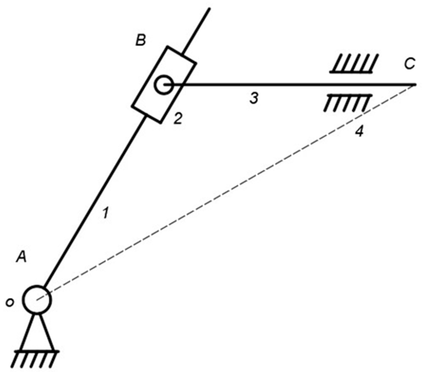
When using a red jujube vibrating device based on adjustable amplitude and frequency to vibrate the jujube tree, the size of the tilt angle of the vibration dial determines the output amplitude of the device to the jujube tree. To analyze the mechanism’s motion state easily, this study abstracts the vibration dial as a crank and the vibration rod as a linkage. The crank and linkage are connected by a slider, resulting in the structural sketch of the excitation mechanism as depicted in Figure 3.
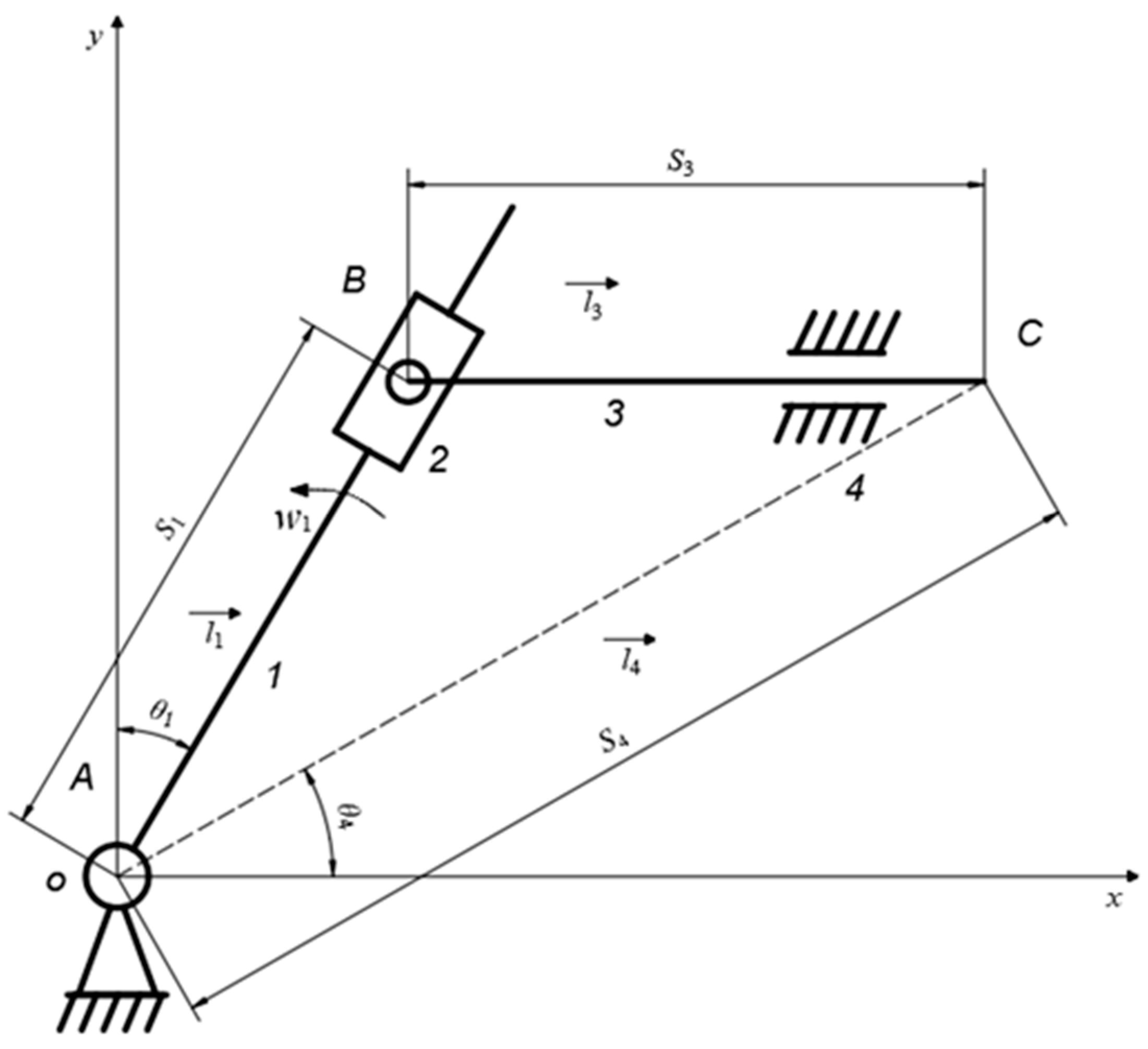
To simplify the kinematic analysis of the excitation mechanism, this study standardizes the kinematic state of each member in the model. Each member is affected only by its force and is independent of its working condition or other states. The vector direction of each member is determined by the direction of force transmission. An xoy coordinate system with the origin O at the center of the vibration dial circle is established, as illustrated in Figure 4. Relevant parameters and descriptions are presented in Table 1.
As shown in Figure 4, S 1 , S 3 and ω 1 are known quantities and S 4 , θ 1 and θ 4 are unknown quantities. To solve for the relevant parameters, a closed vector equation needs to be established, as shown in Equation (1):
l 1 + l 3 = l 4 .
The vibration rod of the excitation mechanism has a certain height relative to the device frame, and the equation is projected on the coordinate axis as shown in Equation (2):
s 1 cos θ 1 s 4 sin θ 4 = 0 s 1 sin θ 1 s 4 cos θ 4 = s 3 s 4 sin θ 4 = h .
The system of equations is rewritten into matrix form as shown in Equation (3):
cos θ 1 sin θ 4 0 sin θ 1 cos θ 4 0 0 sin θ 4 0 s 1 s 4 θ 4 = 0 s 3 h .
The three motion variables S 4 , θ 1 and θ 4 can be derived from matrix Equation (3). Then, the matrix Equation (3) is taken as a derivative for time t and written in the form of a matrix equation. The excitation mechanism velocity equation is obtained as shown in Equation (4):
cos θ 1 sin θ 4 s 4 cos θ 4 sin θ 1 cos θ 4 s 4 sin θ 4 0 sin θ 4 s 4 cos θ 4 s 1 s 4 w 4 = w 1 s 1 sin θ 1 s 1 cos θ 1 0 .
The second derivative of matrix Equation (3) for time t is obtained and written in the form of matrix equation, that is, the acceleration equation of the excitation mechanism is obtained, as shown in Equation (5):
cos θ 1 sin θ 4 s 4 cos θ 4 sin θ 1 cos θ 4 s 4 sin θ 4 0 sin θ 4 s 4 cos θ 4 s 1 s 4 α 4 = s 1 sin θ 1 α 1 + 2 s 4 cos θ 4 w 4 s 4 sin θ 4 w 4 2 s 1 cos θ 1 α 1 2 s 4 sin θ 4 w 4 s 4 cos θ 4 w 4 2 2 s 4 cos θ 4 w 4 + s 4 sin θ 4 w 4 2 + w 1 2 s 1 sin θ 1 + s 1 cos θ 1 w 1 2 s 1 cos θ 1 + s 1 sin θ 1 w 1 0 .

2.2.3. Simulation of Excitation Mechanism

The excitation mechanism of the red jujube harvesting device is driven by the rotation of the drive shaft, which in turn drives the circular motion of the vibration dial. The vibration rod, driven by the vibration dial, converts the circular motion of the vibration dial into the linear motion of the vibration rod, thereby achieving the reciprocating motion of the excitation mechanism. To investigate the motion of the excitation mechanism, kinematic simulation was performed, and the displacement, velocity, and acceleration of the end of the vibration rod were analyzed. The motion simulation was carried out in ADAMS2018 based on the working principle of the excitation mechanism.
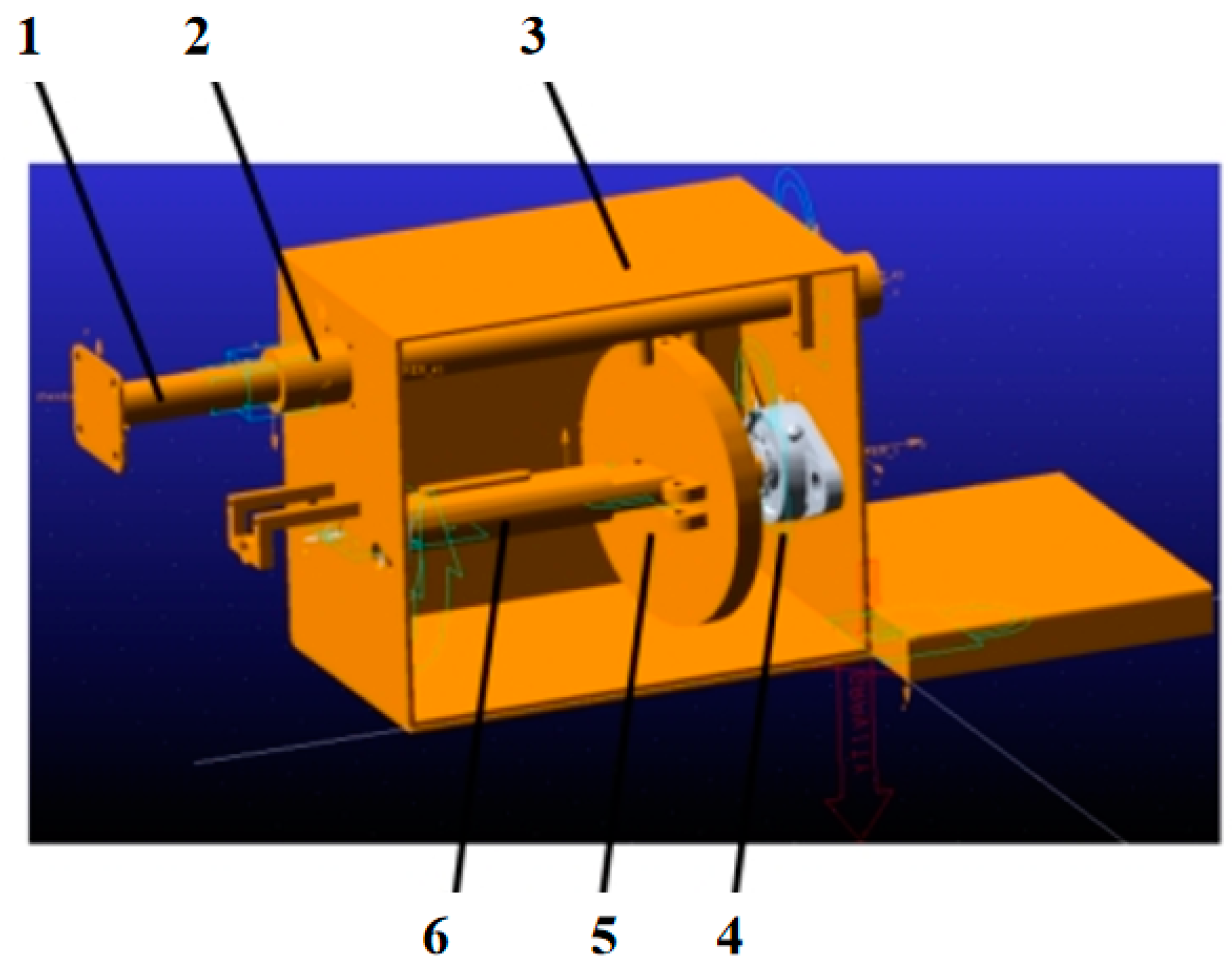
To improve the simulation speed of the model, only the essential working components of the excitation mechanism were retained in this study when importing the model. These parts included the vibration rod, linear bearing, device frame, diamond bearing, drive shaft, and amplitude modulation dial, as illustrated in Figure 5. The device frame served as the fixed component of the excitation mechanism and was fixedly constrained, while the diamond bearing was in contact with the device frame. The drive shaft was mounted on the diamond bearing, and the vibration dial was mounted on the drive shaft. The vibration rod was attached to the top of the vibration dial, and the linear bearing formed the moving amplitude. Before simulating the mechanism, the material properties of each component were set, and the drive settings were established. The vibration frequency of the vibration rod was set to 30 Hz, the simulation time was set to 1 s, and the number of simulation steps was 360.

2.3. Design of Red Jujube Collection Mechanism

This section focuses on the design and evaluation of a fruit collection mechanism specifically for red jujubes. We begin by comparing existing fruit collection mechanisms and selecting the one most suitable for jujube harvesting. Using NX 12.0, we design a 3D model of the fruit collection mechanism. To assess its feasibility and reliability, we construct a collision model between the jujube and the umbrella surface to obtain the collision pressure. The reliability of the fruit collection mechanism is analyzed through static simulation analysis, while its feasibility is assessed through kinematic simulation analysis. With these analyses, the aim is to complete the jujube fruit collection mechanism of the jujube vibrating picking device.

2.3.1. Selection of Fruit Collection Mechanism

In fruit vibration harvesting, the fruits often suffer damage when they collide with the contact surface, which in turn affects their quality and storage time. To minimize fruit damage and increase harvesting efficiency, collection devices are commonly used in conjunction with vibration harvesting to collect and protect the fruits. The traditional collection method involves manually placing flexible materials like cloth or plastic under the fruit tree. While this method is simple and effective, it is time-consuming, labor-intensive, and requires a large number of workers to cooperate, limiting fruit protection.
Existing mechanized fruit collection mechanisms primarily include two types: the foliate fruit collection mechanism and the inverted umbrella fruit collection mechanism. The foliate fruit collection mechanism consists of a telescopic mechanism, supporting wheel, and umbrella surface. Its operation involves extending the telescopic mechanism to surround the fruit tree, causing the fruits to vibrate and fall onto the canvas of the collection mechanism. After vibration, the telescopic mechanism contracts, and the fruits are collected on a mobile platform for sorting, packaging, and collection. While this device effectively collects fruits, the flat contact surface causes fruits to fall and collide with it, resulting in significant force and potential internal damage. Additionally, the rectangular structure design wastes collection space and increases manufacturing costs.
The inverted umbrella-shaped fruit collection mechanism comprises an umbrella surface, an umbrella bone, and a telescopic mechanism. This device surrounds the fruit tree with the umbrella surface, allowing shed fruits to fall into it and facilitating the collection process. The round shape of the umbrella surface fits the fruit tree better, minimizing collection space waste, reducing manufacturing costs, device size, and improving device maneuverability.
Building upon the existing collection devices, this study proposes an inverted umbrella fruit collection mechanism based on the parallelogram mechanism. By modifying the mechanical structure of the parallelogram mechanism and transforming its linear motion into circular motion, the mechanism can enclose the fruit tree. Additionally, by incorporating a tilted design for the umbrella bone, the umbrella surface forms an inclined angle with the horizontal surface. This design reduces the contact force when the fruits touch the umbrella surface, ensuring high-quality fruit harvesting while minimizing damage.

2.3.2. Design and Principle of Fruit Collection Mechanism

Based on measurements, the diameter of the jujube tree canopy is approximately 2 m. To ensure the smooth entry of red jujubes that are shed by vibration into the fruit collection mechanism, the diameter of the umbrella of the fruit collection mechanism should be greater than 2 m. As the maximum trunk diameter of 3-, 5-, and 7-year-old jujube trees is 100 mm, the central opening of the fruit collection mechanism should be greater than 100 mm when the mechanism is closed. However, to prevent fruit leakage, the opening diameter should not be too large. Given that the minimum diameter of red jujube is 6 mm, the opening diameter of the fruit collection mechanism should range from 100 mm to 105 mm. The umbrella of the fruit collection mechanism should have an inverted umbrella shape to facilitate fruit collection.
This study presents the design of an inverted umbrella-type red jujube collection device tailored to the characteristics of red jujube and orchard picking environment. The main structure of the device includes an umbrella surface, umbrella bone, umbrella frame, fruit collection rack, fruit collection gear, fruit collection motor, and fruit collection frame, as shown in Figure 6a. The fruit collection frame is located under the vibration device and clamping device, and the fruit collection motor is fixed under the fruit collection frame. The fruit collection gear is installed at the end of the motor’s shaft, and the fruit collection rack is installed in the fruit collection frame and connected to the gear. The umbrella frame is hinged with the fruit collection frame and the fruit collection rack, and the umbrella bone is fixed at a certain angle on the umbrella frame. The umbrella surface is mounted on the umbrella bone. The movement of the fruit collection mechanism follows the principle of “circular motion—linear motion—circular motion” as depicted in Figure 6b. The gear’s circular motion is transformed into the linear motion of the gear rack through their meshing. The linear motion of the rack is then converted into the circular motion of the gear rack, followed by the linear motion of the rack again, which is transformed into the circular motion of the fruit collection mechanism through the rod mechanism. Once the device reaches the designated position, the fruit collection motor starts to work. The fruit collection gear engages with the fruit collection rack, which in turn performs linear motion to control the movement of the umbrella frame. When the fruit collection motor moves clockwise, the fruit collection umbrella starts to close. Conversely, when the fruit collecting motor moves counterclockwise, the fruit collecting umbrella starts to open.
During the red jujube collection process, the umbrella bone plays a crucial role in the fruit collection mechanism. The ability of the umbrella bone to support the weight of the entire umbrella surface and keep it stable during the fruit drop collection process directly affects the efficiency of red jujube collection. Thus, it is essential to calculate the impact force on the umbrella surface caused by the falling red jujubes. This calculation helps simulate the force on the umbrella bone of the fruit collection mechanism and verify the mechanism’s deformation when subjected to impact force.
To ensure the smooth collection of red jujubes, the umbrella surface of the fruit collection mechanism should be designed with a specific inclination angle. The range of the inclination angle θ can be determined using Equation (6):
θ > arctan μ .
The inclination angle of the umbrella bone needs to satisfy Equation (6) to collect red jujube. In this study, a PVC canvas is chosen as the material for the umbrella, with a static friction coefficient of 0.5. The design parameters for the umbrella are a pole length of 1.6 m, a thickness of 3 mm, an inclination angle of 30°, and a material of 304 stainless steel. During the red jujube shedding process, the fruit falls freely and the maximum height from the fruit to the fruit collection mechanism’s umbrella surface during vibration is 2 m, with g = 9.8 m/s2. Therefore, the velocity of the red jujube when it reaches the umbrella surface during vibration can be calculated using Equation (7):
v = 2 g h = 6.26   m/s .
The formula for calculating the impact force is shown in Equation (8):
F = m v T .
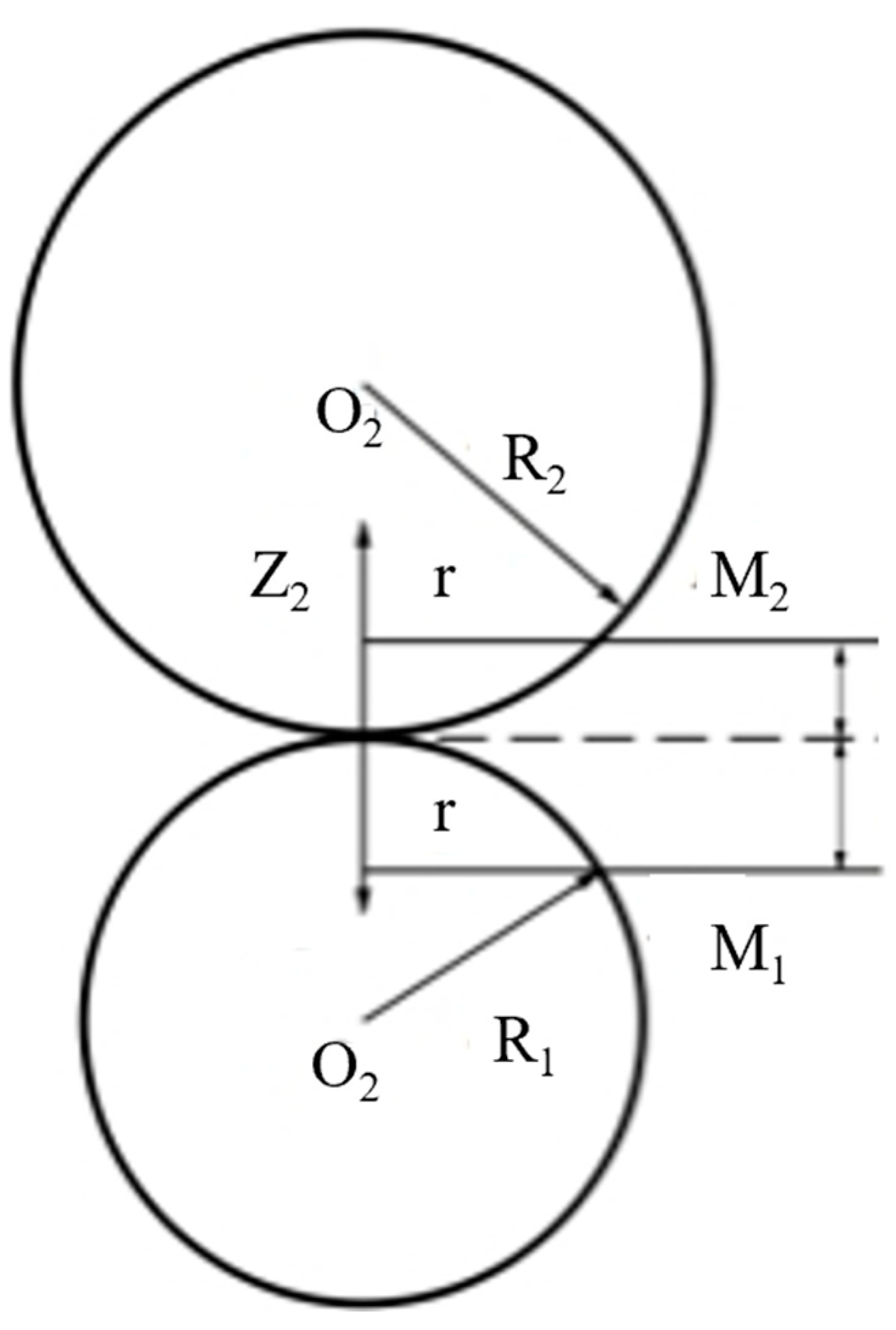
According to Equation (8), the impact force between a red jujube and the umbrella surface depends on the collision time, collision velocity, and the fruit’s mass. As the collision time is very short and varies with different contact surfaces, the red jujube is simplified to a small ball, and the umbrella is simplified to a small ball with an infinite radius in this study to facilitate analysis and calculation of the collision time. The collision process between the two spheres involves two phases: squeezing and recovery. In the squeezing phase, the two spheres start from contact collision, and the distance between their centers gradually decreases due to sphere deformation, converting kinetic energy to mechanical energy. In the recovery phase, the mechanical energy between the balls converts to kinetic energy, restoring the ball deformation, expanding the distance between the centers of the balls, increasing the relative speed until the balls separate. The two balls have masses m1, m2, radii R1, R2, Poisson’s ratios µ1, µ2, and Young’s moduli E1, E2. The relative velocity of the two balls before collision is v, and their contact point is O. The centers of the two balls are O1 and O2, and the surface of the two spheres intersect at M1 and M2, with M1 and M2 distances from the tangent plane being l1 and l2, as shown in Figure 7.
When the intersection points M1 and M2 of the two spherical surfaces at a distance r from the common normal are close to point O, then l1 is much smaller than R1 and l2 is much smaller than R2, which leads to Equation (9):
x 1 + x 2 = α ( R 1 + R 2 2 R 1 R 2 ) r 2 ,
where a is the distance between the spherical centers O1 and O2 approaching each other due to compression, x 1 denotes the displacement of M1 along the Z1 direction, and x 2 denotes the displacement of M2 along the Z2 direction.
Since the contact surface is a circle centered on the contact point O, as shown in Figure 7, A is the radius of the contact circle and M is the point M1 before deformation. Then, the displacement of point M1 is shown in Equation (10):
x 1 = 1 v 1 2 π E 1 q d s d θ ,
where v1 and E1 are the elastic constants of the sphere, q is the vertical pressure on the contact surface, d s is the distance from the point on the contact surface to the M1 point, and d θ is the angle from the point on the contact surface to the M1 point.
Similarly, the displacement at point M2 in the contact surface of the other ball can be obtained as shown in Equation (11):
x 2 = 1 v 2 2 π E 2 q d s d θ ,
where v2, E2 are the elastic constants of the sphere, q is the vertical pressure on the contact surface, d s is the distance from the point on the contact surface to the point M2, and d θ is the angle from the point on the contact surface to point M2.
Summing Equation (10) and Equation (11) yields Equation (12):
( k 1 + k 2 ) q d s d θ = α β r 2 ,
where k 1 = 1 v 1 2 π E 1 , k 2 = 1 v 2 2 π E 2 .
We let q 0 represent the force at the center of the contact circle, which is linearly distributed along the radius of the contact circle. At any point on the contact surface, the pressure is the product of the point’s height h and the pressure distribution coefficient k. Equation (13) can be obtained:
( k 1 + k 2 ) 2 0 π 2 q 0 a π 2 ( a 2 r 2 sin 2 θ ) d θ = α β r 2 .
According to the equilibrium conditions, the sum of the distributed forces in the hemisphere should be equal to the total pressure F, as shown in Equation (14):
q 0 a 2 3 π a 3 = F .
We solve for a , α and q 0 by combining Equations (13) and (14) as shown in Equation (15):
a = ( 3 π F ( k 1 + k 2 ) R 1 R 2 4 ( R 1 + R 2 ) ) 1 3 α = ( 9 π 2 F 2 ( k 1 + k 2 ) 2 ( R 1 + R 2 ) 16 R 1 R 2 ) 1 3 q 0 = 3 F 2 π ( 4 ( R 1 + R 2 ) 3 π F ( k 1 + k 2 ) R 1 R 2 ) 2 3 .
Equation (15) is collapsed to solve for the contact pressure F between the two balls as shown in Equation (16):
F = N α 2 3 ,
where N = 4 3 π ( k 1 + k 2 ) R 1 R 2 R 1 + R 2 .
When the two balls collide against the center, force F causes deceleration in the sphere’s motion. During the contact phase, the compression distance of the surfaces is zero, and at this point, the relative velocity of the two spheres is v r 0 . As the spheres are compressed by distance α , their relative velocity becomes v r = d a / d t , resulting in Equation (17):
1 2 [ ( d α d t ) 2 v r 0 2 ] = 2 5 N M α 5 2 ,
where M = m 1 m 2 m 1 + m 2 , M is the folded mass of the two spheres.
When the relative velocity of the two balls is zero, the maximum compression distance of the two balls at this time is shown in Equation (18):
α max = ( 5 4 M N v r 0 2 ) 2 5 .
We let x = α / α max when t = 0, x = 0. When the compression phase ends t, x = 1, at which point we can proceed to Equation (19):
t = 2 5 α max v r 0 0 1 y 2 5 1 ( 1 y ) 1 2 d y = 2 5 α max v r 0 0 1 y 2 5 1 ( 1 y ) 1 2 1 d y = 2 5 α max v r 0 β ( 2 5 , 1 2 ) = 2 5 α max v r 0 Γ ( 2 5 ) Γ ( 1 2 ) Γ ( 2 5 + 1 2 ) = 1.47 α max v r 0 ,
where Γ ( 2 5 ) = 2.2185 , Γ ( 1 2 ) = 1.7724 , Γ ( 2 5 + 1 2 ) = 1.0687 .
The total contact time of the two spheres is equal to the sum of the compression phase and the recovery phase time, where K is the recovery factor as shown in Equation (20):
T = t 1 + t 2 = 1.47 ( 5 4 M N ) 2 5 1 v r 0 1 5 ( 1 + 1 K 1 5 ) .
In this study, the maximum weight and dimensions of a single mature red jujube were measured as 1.858 × 10 −2 kg, 4.253 × 10 −2 m (long axis diameter), and 3.067 × 10 −2 m (short axis diameter), respectively. To simplify the collision analysis, the red jujube was modeled with a diameter of 3.000 × 10 −2 m. The Young’s modulus and Poisson’s ratio of the red jujube were determined as 3.750 × 10 5 Pa and 0.4 [30], respectively, while those of the stainless steel material of the umbrella were 1.940 × 10 11 Pa and 0.3 [31], respectively. When a red jujube was dropped from a height of one meter and collided with the stainless steel surface, it rebounded to a height of 0.200 m with a recovery coefficient of 0.200. By substituting these parameters into Equation (20), the collision time between the red jujube and the umbrella bone was calculated as T = 0.0046 s. The pressure on the umbrella bone at the point of impact was 25.030 N, with a positive pressure of 21.677 N, which was obtained using Equation (16).

2.3.3. Static Analysis of Fruit Collection Mechanism

The fruit collection mechanism mainly utilizes the umbrella surface, umbrella bone, and umbrella frame to collect the red jujubes. The umbrella bone and frame act as the primary support components during the vibration harvesting of red jujubes, ensuring the success of the fruit collection operation. Therefore, in this study, a stress–strain analysis of the umbrella bone and frame is conducted separately using ANSYS 16.0 software. The following are the steps for conducting static analysis on the umbrella bone and frame in the fruit collection mechanism:
(1)
Geometric modeling.
First, the 3D model of the umbrella bone and umbrella frame was constructed in UG NX 12.0, and the static analysis was performed in Workbench software. To improve the computational efficiency of the model, connection parts such as bolts, nuts and spacers can be ignored during the analysis to reduce the computational time of the model.
(2)
Adding material properties.
The material of the umbrella bone and umbrella frame is 304 stainless steel with a thickness of 3 mm, a modulus of elasticity of 1.940 × 10 11 Pa, a Poisson’s ratio of 0.3, and a material density of 7.93 × 10 3 kg/m3.
(3)
Mesh division.
The cell size of the umbrella bone was set to 1 mm, and 59,665 nodes and 32,147 grid cells were generated; the cell size of the umbrella frame was set to 1 mm, and 49,296 nodes and 9816 grid cells were generated as shown in Figure 8.
(4)
Adding constraints and loads.
As the red jujube vibrates off, the force generated by the collision with the fruit collection mechanism is a vertical downward force, and the farthest point of the umbrella bone experiences the maximum moment. Therefore, a force of 26 N is applied to the farthest point of the umbrella bone from the fixed end, and the direction is along the negative z-axis. For the umbrella frame, the force applied is the sum of the gravity of the umbrella bone and the collision pressure of the red jujube. One end of the umbrella frame is fixed, and a force of 30 N is applied to the other end, in the direction of the negative z-axis.
(5)
Hydrostatic analysis.
The ANSYS Workbench program solver was utilized to obtain the displacement, strain, and stress states of the umbrella bone and umbrella frame.

2.3.4. Kinematic Analysis of the Fruit Collection Mechanism

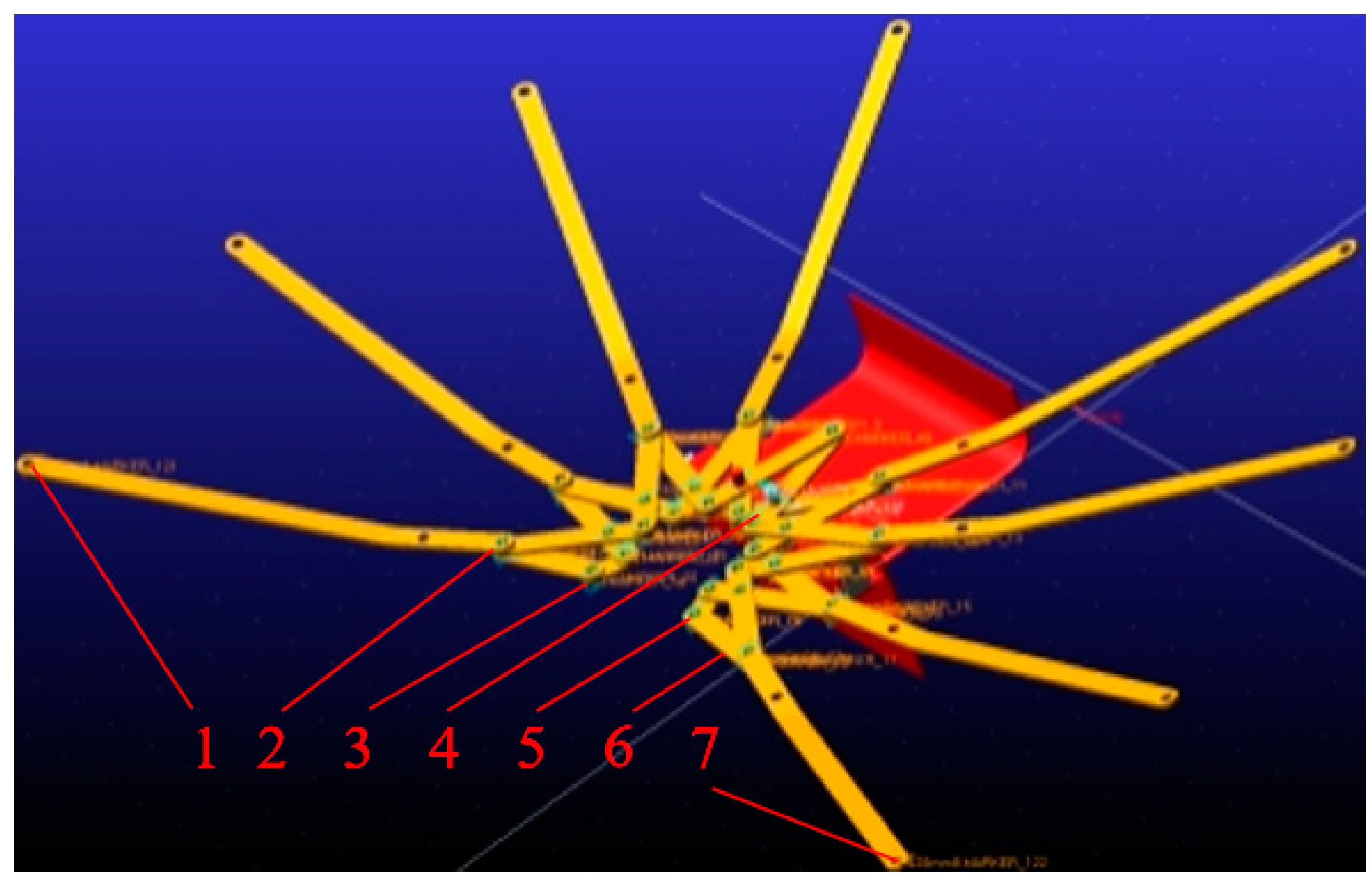
The fruit collection mechanism plays a crucial role in the red jujube collection process, and its motion directly impacts the effectiveness of the red jujube collection. To validate the fruit collection mechanism design, a kinematic simulation of the fruit collection umbrella movement was conducted after the design was completed. The displacement, velocity, and acceleration of the critical parts of the umbrella were measured and analyzed. To increase simulation speed, only the essential working parts of the fruit collection mechanism, the umbrella bone, umbrella frame, fruit collection rack, and fruit collection frame were included in the model, and fixed and rotational sub-constraints were applied to various parts of the mechanism. The model was pre-processed, including material properties and drive settings, before simulating the mechanism. Figure 9 illustrates the fixed and rotational sub-constraints applied to the mechanism and shows the selected key point positions. The simulation had a duration of 10 s with 1000 simulation steps.

2.4. Red Jujube Vibratory Harvesting Device Testing

2.4.1. Red Jujube Vibrating Harvesting Device Excitation Mechanism Test

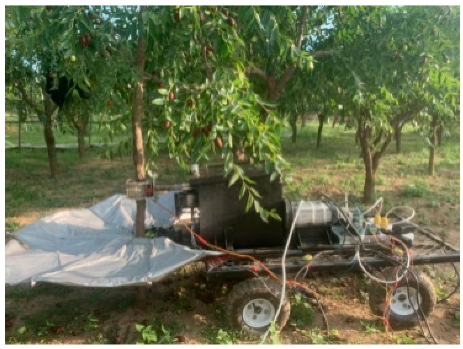
To confirm the capability of the red jujube vibration harvesting device in harvesting trees with varying fruit diameters using different vibration amplitudes and frequencies, a series of tests were conducted. These tests involved different red jujube diameters and combinations of vibration frequency and amplitude. The testing procedure is illustrated in Figure 10.
In this test, vibration tests were conducted for different diameters of jujube trees. First, the diameter of the jujube tree trunk was measured using a depth camera. Then, the vibration amplitude and vibration frequency of the excitation mechanism were adjusted, and the jujube tree was clamped using the clamping mechanism. The excitation mechanism started to vibrate the jujube tree for harvesting.
In a prior study focused on optimizing vibration parameters for varying diameters of jujube trees, vibration tests were carried out on jujube trees with diameters of 30 mm, 50 mm and 70 mm. Through single-factor and multi-factor experimental analyses, the most optimal vibration parameters for each diameter of the jujube tree were determined [32]. The findings from this study served as the foundation for the vibration parameters used in this current study for varying diameters of jujube trees. To ensure the accuracy of the device in adjusting the vibration frequency and vibration amplitude, the device followed the following principles in adjusting the vibration frequency and vibration amplitude: when the diameter of the jujube tree was between 29.15 mm and 31.26 mm, the vibration parameters were combined as a vibration frequency of 30 Hz, a vibration amplitude of 15 mm, and a vibration time of 9 s; when the diameter was between 49.56 mm and 52.34 mm, the vibration parameters were 19 Hz, 13 mm amplitude, and 9 s. When the diameters ranged from 65.23 mm to 73.25 mm, the vibration parameters were 6 Hz, 15 mm amplitude, and 9 s. In the test, multiple replications were conducted for each diameter of the jujube tree and the total weight of vibrated red jujubes was recorded as an evaluation index. The net collection rate was used as the evaluation index of the device, as shown in Equation (21):
R = Q a Q a + Q n × 100 % ,
where R is the net harvesting rate of red jujube, %; Q a is the total weight of successfully harvested red jujube, kg; Q n is the total weight of unsuccessfully harvested red jujube, kg.

2.4.2. Fruit Collection Mechanism Test of Red Jujube Vibrating Harvesting Device

To confirm the fruit collection efficiency of the red jujube vibrating harvesting device’s fruit collection mechanism for jujube trees with varying diameters, a fruit collection tests were conducted. The test process is depicted in Figure 11.
In this study, fruit collection experiments were carried out for jujube trees of different diameters. Initially, the diameter of the jujube trees was measured using a depth camera. The fruit collection motor was then started, and the fruit collection mechanism was controlled to close. The clamping device was used to clamp the trunk of the jujube trees, and the excitation mechanism started to vibrate. The vibrated fallen red jujubes were collected by the fruit collection mechanism, and the total weight of the vibrated fallen red jujubes and the total weight of the red jujubes in the fruit collection mechanism was recorded. The fruit collection efficiency was used as an index to evaluate the performance of the mechanism in this experiment, as shown in Equation (22):
L = W a W n × 100 % ,
where L is the fruit collection efficiency of red jujube, %; W n is the total weight of vibrating fallen red jujube, kg; W a is the total weight of red jujube in the fruit collection mechanism, kg.

3. Results

3.1. Results of Simulation Analysis of the Excitation Mechanism

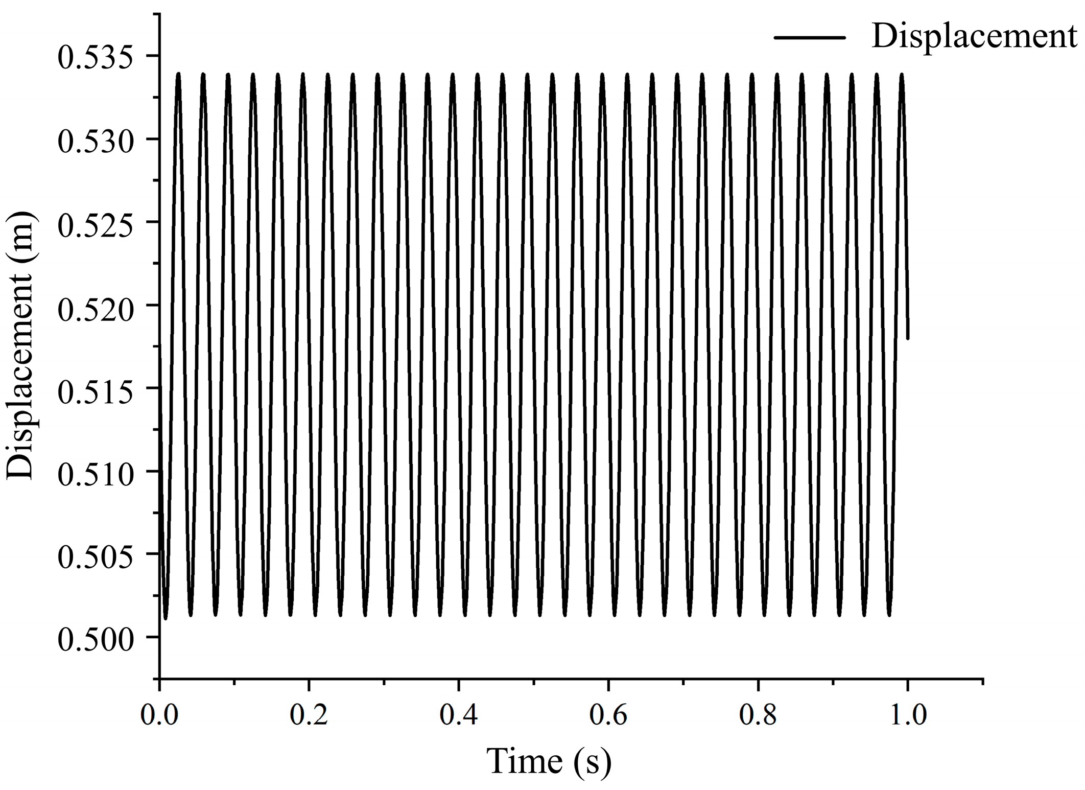
According to the simulation test setup outlined in Section 2.2.3, a simulation analysis was conducted to assess the excitation mechanism’s performance and characteristics. After conducting the motion simulation of the excitation mechanism, the displacement, velocity, and acceleration of the vibration rod were measured, and the resulting variation curves were analyzed. Figure 12 shows the displacement simulation curve of the vibration rod, which indicates that the displacement of the vibration rod changes as a cosine function with time, with a simulation period of 0.03 s. The maximum displacement value is 0.534 m, the minimum value is 0.501 m, and the average displacement amplitude is 0.016 m. These results suggest that the mechanism can carry out small high-frequency vibrations during the harvesting of fruit trees, and the amplitude remains relatively stable. This stability is beneficial for the stable vibration of different diameters of trunks, ensuring a more effective harvesting process.
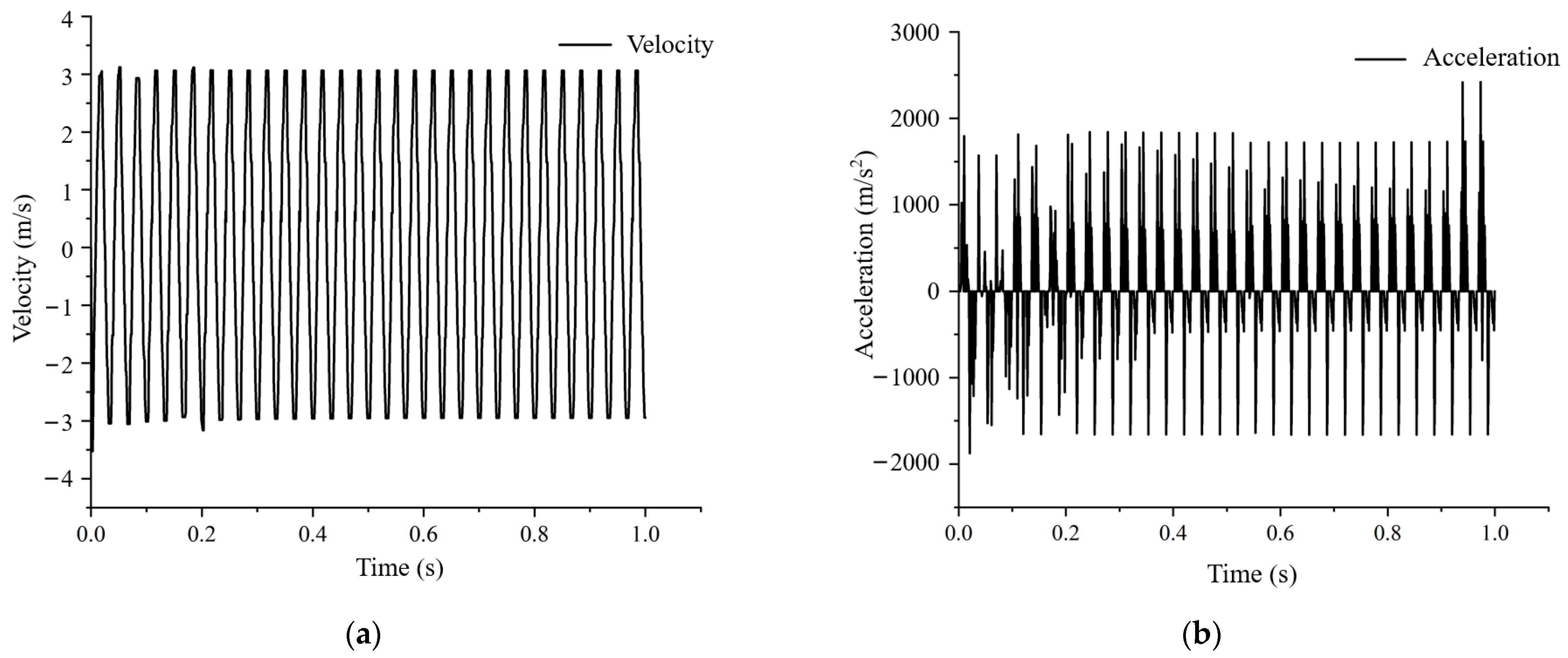
The variation of the velocity of the vibration rod is presented in Figure 13a, which also exhibits periodic changes with time, and the period is the same as that of the displacement, at 0.03 s. The maximum and minimum values are 3.120 m/s and −3.526 m/s, respectively, with an average velocity amplitude of 3.062 m/s. The velocity curve shows a slow–sharp–slow change twice in one cycle. Figure 13b shows the acceleration change in the vibration rod, which displays a sharp increase and decrease with time, indicating a sharp return characteristic of the mechanism. According to Newton’s second law, the vibration rod can generate an impact force that is two times larger than the average force in one cycle. Therefore, the mechanism is advantageous for fruit shedding through vibration.

3.2. Results of Simulation Analysis of the Fruit Collection Mechanism

3.2.1. Results of Static Analysis of the Fruit Collection Mechanism

The static analysis of the fruit collection mechanism was conducted based on the test setup specified in Section 2.3.2. The displacement, strain, and stress clouds of the umbrella bone and umbrella frame are shown in Figure 14, and the corresponding analysis results are presented in Table 2. As observed from Figure 14, the maximum displacement of the umbrella bone is at the farthest point from the fixed end, while the highest stress and strain occur at the bend of the umbrella bone.
Since the umbrella frame is expected to have a certain degree of displacement during red jujube harvesting and the material’s yield strength is 310 MPa, the analysis results in Table 2 demonstrate that the umbrella frame’s design satisfies the requirements of the red jujube vibration harvesting apparatus. The umbrella frame’s farthest point from the fixed end underwent the maximum displacement, whereas the maximum stress and strain occurred at the middle bolt fixation. Nonetheless, the maximum stress was considerably lower than the material’s yield strength, guaranteeing that the umbrella frame design is sufficient for red jujube harvesting.

3.2.2. Results of Kinematic Analysis of Fruit Collection Mechanisms

The kinematic analysis of the fruit collection mechanism was carried out following the test setup outlined in Section 2.3.3. After the simulation, displacement, velocity, and acceleration curves were generated for the key positions of the fruit collection mechanism to analyze the movement of the rod.
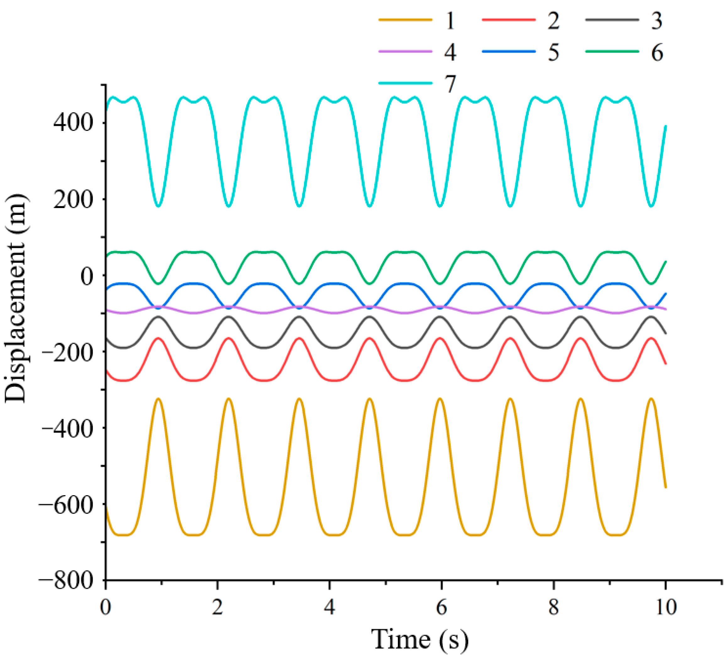
Based on Figure 15, the displacement of each key point in the fruit collection mechanism changes over time. Key points 1, 2, and 3 have the same motion trends, as do Key points 5, 6, and 7, due to the symmetric design of the fruit collection device. The motion amplitude and frequency of Key points 5 and 6 are the same, and the motion amplitude and frequency of Key points 2 and 3 are also the same, as they are on the same rod. Key points 1 and 7 have the same motion amplitude and frequency due to the symmetric design and equal rod lengths, causing the corresponding rods on both sides of the fruit collection mechanism to move in opposite directions with the same amplitude and frequency. Therefore, the mechanism achieves synchronization in left and right displacements during the red jujube collection process.
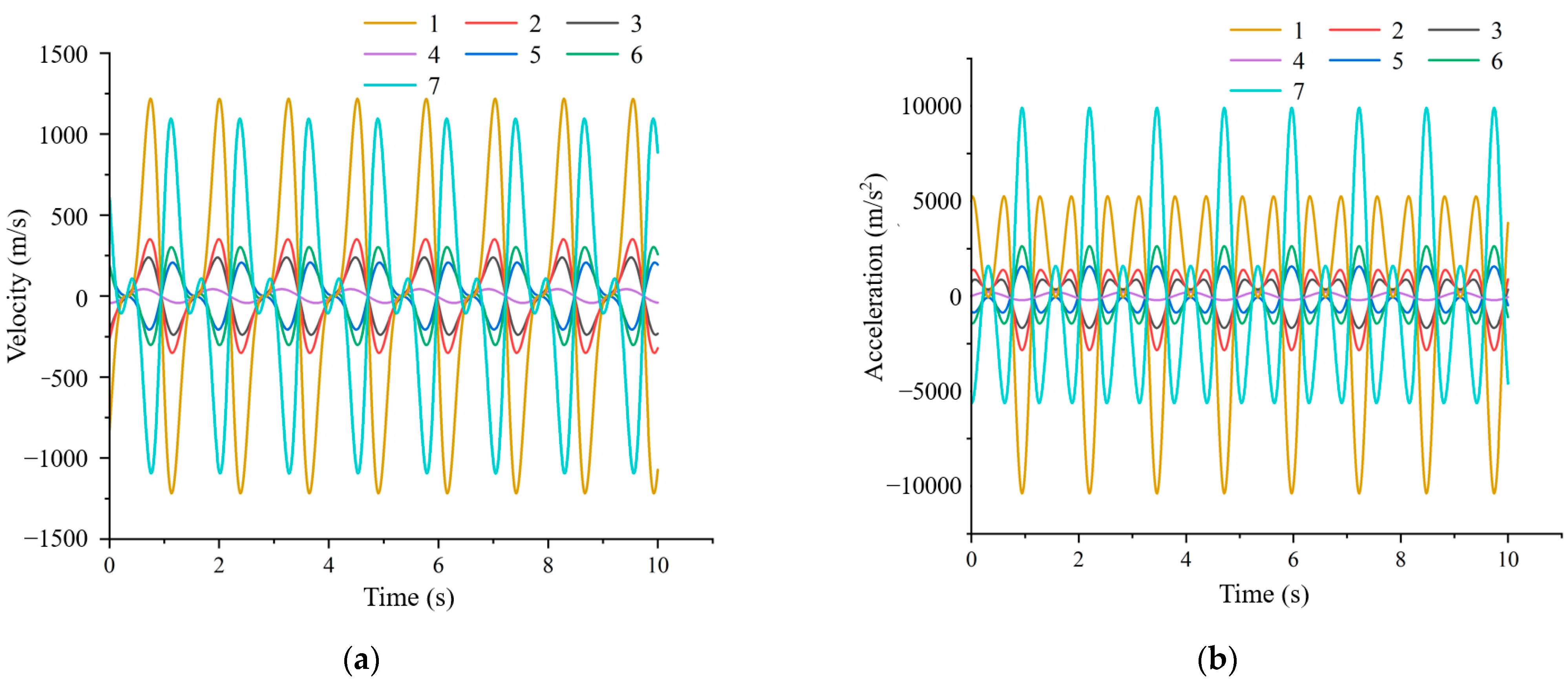
In Figure 16a, it is evident that when the drive is set to periodically vary, the velocity of each key point displays a periodic variation with time, with the same variation period. The amplitude of velocity change in Key point 1 and Key point 7 is larger, with Key point 7 having a slightly smaller amplitude than Key point 1. This difference in amplitude is due to the installation position of Key point 7 being slightly later than that of Key point 6 during the assembly of the device. The changes in other key points have similar trends with displacement changes, with the velocity frequencies of Key point 5, Key point 6, and Key point 7 being the same, and the velocity frequencies of Key point 1, Key point 2, and Key point 3 being the same. However, Key point 5, Key point 6, and Key point 7 have different amplitudes of velocity change, and Key point 1, Key point 2, and Key point 3 have different amplitudes of velocity change. The farther away the key point from the driving position, the larger its key point speed amplitude, resulting in the mechanism being able to achieve left and right speed synchronization during the collection of red jujubes.
In Figure 16b, it is apparent that when the drive is set to periodically vary, the acceleration of each key point also displays periodic variation with time, with the same variation period. The amplitude of acceleration variation of Key point 1 and Key point 7 is larger, with Key point 7 having the same amplitude as Key point 1, perhaps due to the difference in force at its end point, despite the installation position of Key point 7 being slightly behind that of Key point 6. When comparing Key point 1, Key point 2, and Key point 3, it can be observed that the farther away the key point from the driving position, the larger its key point acceleration amplitude. This ensures the mechanism maintains balance between the left and right driving force during the collection of red jujubes.

3.3. Test Analysis of Red Jujube Vibrating Harvesting Device

3.3.1. Test Analysis of Red Jujube Vibrating Harvesting Device Excitation Mechanism

The study employed different vibration parameters for jujube trees with varying diameters. Table 3 showcases the results of the tests conducted using different excitation mechanisms.
From Table 3, it can be observed that for jujube trees with diameters ranging from 29.15 to 31.26 mm, the net harvesting rate exceeded 90.00%, with an average net harvesting rate of 93.98% and a standard deviation of 0.57%. Jujube trees with diameters ranging from 49.56 to 52.34 mm had a net harvesting rate of around 94.00%, with the highest average net harvesting rate and the smallest standard deviation among the three diameters. Therefore, the vibratory harvesting device had the best harvesting effect for jujube trees with diameters ranging from 49.56 to 52.34 mm, with the smallest gap between the net harvesting rates. Jujube trees with diameters ranging from 65.23 to 73.25 mm had an average net harvesting rate of 94.33%, with the largest standard deviation among the three diameters. Thus, the vibratory harvesting device had a greater difference in the harvesting effect for jujube trees with diameters ranging from 65.23 to 73.25 mm. The significant difference in the total weight of red jujubes for jujube trees with similar diameters was primarily due to the external forces causing a large number of red jujubes to fall off after maturation before the vibration harvesting experiment. The main reason for the certain difference in the net harvesting rate under different diameters was the variation in the physical properties of different jujube trees and the inherent frequencies between different jujube trees, leading to differences in the net harvesting rate.

3.3.2. Test Analysis of Fruit Collection Mechanism of Red Jujube Vibrating Harvesting Device

The results of the fruit collection mechanism for jujube trees with diameters of 30 mm, 50 mm and 70 mm, respectively, are shown in Table 4.
Table 4 reveals that the fruit collection efficiency was highest for jujube trees with diameters between 29.15 to 31.26 mm. The average fruit collection efficiency was also the highest among the three diameter ranges, with experimental fruit collection efficiencies above 95%. However, there was a larger standard deviation in the fruit collection efficiency at 1.00%, indicating greater variability in fruit collection efficiency for jujube trees of this diameter range. Hence, the fruit collection mechanism was most effective for jujube trees of this diameter range, but the fruit collection effect varied significantly across different jujube trees.
On the other hand, for jujube trees with diameters between 49.56 and 52.34 mm, the average fruit collection efficiency was 89.43%, and the standard deviation of the fruit collection efficiency was the smallest. This implies a reduced fruit collection effect for jujube trees in this diameter range, but the fruit collection effect varied the least among different jujube trees.
For jujube trees with diameters between 65.23 and 73.25 mm, the average fruit collection efficiency was the lowest, and the standard deviation of the fruit collection efficiency was the largest. The fruit collection mechanism performed poorly for jujube trees in this diameter range, and the variation in fruit collection efficiency between different jujube trees was significant.
The fruit collection efficiency was similar for jujube trees with similar diameters because the canopy diameter of smaller jujube trees was smaller, making it easier for the fruit collection mechanism to wrap around the trees. However, the fruit collection efficiency decreased with increasing trunk diameter as the canopy diameter of jujube trees increased, which resulted in reduced wrapping effect for the fruit collection mechanism.

4. Conclusions

In this study, we developed a red jujube vibrating harvesting device that is adjustable in terms of frequency and amplitude. The design is based on the growth characteristics of the existing jujube trees and the low net harvesting rate of the existing red jujube harvesting machinery. The overall design of the device was carried out to meet the harvesting requirements of jujube trees with different diameters by using different vibration frequencies and amplitudes. The following conclusions were drawn from this study:
(1)
We designed a red jujube excitation mechanism and carried out dynamics simulations of the mechanism. The results show that the acceleration at the end of the vibrating rod of the mechanism has a tendency to sharply increase and decrease, which facilitates the shedding of red jujubes.
(2)
We constructed a collision model between the red jujubes and the fruit collection umbrella, designed a red jujube collection mechanism, and performed structural and kinematic simulations on the key components. The results verify that the mechanism can effectively collect red jujubes.
(3)
The jujube tree excitation mechanism can adopt different vibration amplitudes and frequencies based on the tree’s diameter, resulting in a higher net harvesting rate and better vibration effect.
(4)
When using the fruit collection mechanism to collect the vibrated down red jujubes from jujube trees with different diameters, the fruit collection efficiency is above 80%, and the fruit collection effect is better, meeting the actual production demand.

Author Contributions

Conceptualization, software, writing—original draft, funding acquisition, supervision, Y.H.; Methodology, formal analysis, validation, J.F.; Investigation, data curation, Y.Q.; Writing—review and editing, data curation, C.Y.; Writing—review and editing, W.L.; Writing—review and editing, K.Z.; Writing—review and editing, R.L.; Supervision, Writing—review and editing, R.H. All authors have read and agreed to the published version of the manuscript.

Funding

This research was supported by the Talent start-up Project of Zhejiang A&F University Scientific Research Development Foundation (2021LFR066) and the National Natural Science Foundation of China (31971787(C0043628), 32171894(C0043619)).

Data Availability Statement

The data presented in this study are available on request from the corresponding author.

Conflicts of Interest

The authors declare no conflict of interest.

References

  1. Zhang, X.; Wu, Z.; Cao, C.; Luo, K.; Qin, K.; Huang, Y.; Cao, J. Design and operation of a deep-learning-based fresh tea-leaf sorting robot. Comput. Electron. Agric. 2023, 206, 107664. [Google Scholar] [CrossRef]
  2. Feng, J.; Yu, C.; Shi, X.; Zheng, Z.; Yang, L.; Hu, Y. Research on Winter Jujube Object Detection Based on Optimized Yolov5s. Agronomy 2023, 13, 810. [Google Scholar] [CrossRef]
  3. Serban, A.C. Aging population and effects on labour market. Procedia Econ. Financ. 2012, 1, 356–364. [Google Scholar] [CrossRef] [Green Version]
  4. Jiang, W.; Chen, L.; Han, Y.; Cao, B.; Song, L. Effects of elevated temperature and drought stress on fruit coloration in the jujube variety ‘Lingwuchangzao’(Ziziphus jujube cv. Lingwuchangzao). Sci. Hortic. 2020, 274, 109667. [Google Scholar] [CrossRef]
  5. Wang, J.; Nakano, K.; Ohashi, S. Nondestructive evaluation of jujube quality by visible and near-infrared spectroscopy. LWT Food Sci. Technol. 2011, 44, 1119–1125. [Google Scholar] [CrossRef]
  6. Hoshyarmanesh, H.; Dastgerdi, H.; Ghodsi, M.; Khandan, R.; Zareinia, K. Numerical and experimental vibration analysis of olive tree for optimal mechanized harvesting efficiency and productivity. Comput. Electron. Agric. 2017, 132, 34–48. [Google Scholar] [CrossRef]
  7. Hayashi, S.; Yamamoto, S.; Tsubota, S.; Ochiai, Y.; Kobayashi, K.; Kamata, J.; Kurita, M.; Inazumi, H.; Peter, R. Automation technologies for strawberry harvesting and packing operations in Japan. J. Berry Res. 2014, 4, 19–27. [Google Scholar] [CrossRef] [Green Version]
  8. Sa, I.; Lehnert, C.; English, A.; McCool, C.; Dayoub, F.; Upcroft, B.; Perez, T. Peduncle detection of sweet pepper for autonomous crop harvesting—Combined color and 3-D information. IEEE Robot. Autom. Letters. 2017, 2, 765–772. [Google Scholar] [CrossRef] [Green Version]
  9. Wang, X.; Kang, H.; Zhou, H.; Au, W.; Chen, C. Geometry-aware fruit grasping estimation for robotic harvesting in apple orchards. Comput. Electron. Agric. 2022, 193, 106716. [Google Scholar] [CrossRef]
  10. Fu, L.; Al-Mallahi, A.; Peng, J.; Sun, S.; Feng, Y.; Li, R.; He, D.; Cui, Y. Harvesting technologies for Chinese jujube fruits: A review. Eng. Agric. Environ. Food 2017, 10, 171–177. [Google Scholar] [CrossRef]
  11. Xu, H.; Hua, Y.; He, J.; Chen, Q. The Positive and Negative Synergistic Airflow-Type Jujube Fruit Harvester (P-N JH). Processes 2022, 10, 1486. [Google Scholar] [CrossRef]
  12. Zhuo, P.; Li, Y.; Wang, B.; Jiao, H.; Wang, P.; Li, C.; Niu, Q.; Wang, L. Analysis and experimental study on vibration response characteristics of mechanical harvesting of jujube. Comput. Electron. Agric. 2022, 203, 107446. [Google Scholar] [CrossRef]
  13. Zhao, J.; Tsuchikawa, S.; Ma, T.; Hu, G.; Chen, Y.; Wang, Z.; Chen, Q.; Gao, Z.; Chen, J. Modal analysis and experiment of a Lycium barbarum L. Shrub for efficient vibration harvesting of fruit. Agriculture 2021, 11, 519. [Google Scholar] [CrossRef]
  14. Zhang, J.; Wang, J.; Zheng, C.; Guo, H.; Shan, F. Nondestructive evaluation of Chinese cabbage quality using mechanical vibration response. Comput. Electron. Agric. 2021, 188, 106317. [Google Scholar] [CrossRef]
  15. Wang, W.; Lu, H.; Zhang, S.; Yang, Z. Damage caused by multiple impacts of litchi fruits during vibration harvesting. Comput. Electron. Agric. 2019, 162, 732–738. [Google Scholar] [CrossRef]
  16. Whitney, D.; Smerage, G.; Block, W. Dynamic Analysis Of A Trunk Shaker-Post System J. Trans. ASAE 1990, 33, 1066–1070. [Google Scholar] [CrossRef]
  17. Junming, H.; Weixue, H.; Wei, W.; Hongjie, Z.; Zhi, R. Fruit vibration harvesting technology and its damage. A review. Inmateh-Agric. Eng. 2021, 63. [Google Scholar] [CrossRef]
  18. Meng, X.; Tang, Z.; Sheng, C.; Jia, S.; Liu, W.; Zhou, Y.; Zheng, X. 4YS-24 Red Jujube Harvester. Xinjiang Agric. Mech. 2013, 157, 13–14. [Google Scholar]
  19. Fu, W.; He, R.; Qu, J.; Sun, Y.; Wang, L.; Kan, Z. Design of self-propelled dwarf dense red jujube harvester. J. Agric. Mech. Res. 2014, 36, 106–109. [Google Scholar]
  20. Yang, H.; Kan, Z.; Wang, L.; Fu, W.; He, R.; Sun, Y. Design of dwarf dense red jujube harvesting device. J. Agric. Mech. Res. 2012, 34, 77–80. [Google Scholar]
  21. Wang, C.; Xu, L.; Zhou, H.; Cui, Y.; Cui, H. Development and testing of eccentric forest fruit vibration harvesting machine. Trans. Chin. Soc. Agric. Eng. 2012, 28, 10–16. [Google Scholar]
  22. He, R. Design and Experimental Study of Excitation Device of Self-Propelled Dwarf and Close Planting Jujube Harvester. Master’s Thesis, Shihezi University, Shihezi, China, 2014. [Google Scholar]
  23. Wang, L.; He, R.; Fu, W.; Kan, Z.; Sun, Y.; Chu, S. Optimization of harvesting device parameters for dwarf dense red jujubes. J. Agric. Mech. Res. 2014, 36, 161–163+172. [Google Scholar]
  24. Cui, J.; Zhang, H.; Fu, W.; Kan, Z.; Liu, Y. Design of self-excited vibration force compensated red jujube vibration harvesting test device. J. Agric. Mech. Res. 2017, 39, 18–22+28. [Google Scholar]
  25. Fu, W.; Zhang, Z.; Ding, K.; Cao, W.; Kan, Z.; Pan, J.; Liu, Y. Design and test of 4ZZ-4A2 full-hydraulic self-propelled jujube harvester. Int. J. Agric. Biol. Eng. 2018, 11, 104–110. [Google Scholar] [CrossRef]
  26. Yin, S.; Zhang, T.; Dong, X.; Ran, X.; Sun, X. Design and test of self-propelled red jujube harvesting machine with variable ground clearance. Agric. Eng. 2019, 9, 67–71. [Google Scholar]
  27. Zheng, Z.; Hu, Y.; Guo, T.; Qiao, Y.; He, Y.; Zhang, Y.; Huang, Y. AGHRNet: An attention ghost-HRNet for confirmation of catch-and-shake locations in jujube fruits vibration harvesting. Comput. Electron. Agric. 2023, 210, 107921. [Google Scholar] [CrossRef]
  28. ADAMS, M. Automatic dynamic analysis of mechanical systems. MSC Softw. Corp. 2014. [Google Scholar]
  29. Hou, J.; Qiao, Y.; Guo, T. An Amplitude and Frequency Adjustable Vibration Device Based on Amplitudu Modulation Dial. China Patent CN217742327U, 8 November 2022. [Google Scholar]
  30. Zhang, Z. Optimization Design and Experiment of Jujube Exciter Based on Dynamics Similarity Theory. Master’s Thesis, Shihezi University, Shihezi, China, 2019. [Google Scholar]
  31. Lo, K.H.; Shek, C.H.; Lai, J. Recent developments in stainless steels. Mater. Sci. Eng. R Rep. 2009, 65, 39–104. [Google Scholar] [CrossRef]
  32. Yu, C.; Qiao, Y.; Feng, J.; Guo, T.; Luo, W.; Guo, J.; Hu, Y. Optimization of Vibration Parameters for Jujube Trees with Different Diameters. Forests 2023, 14, 1287. [Google Scholar]
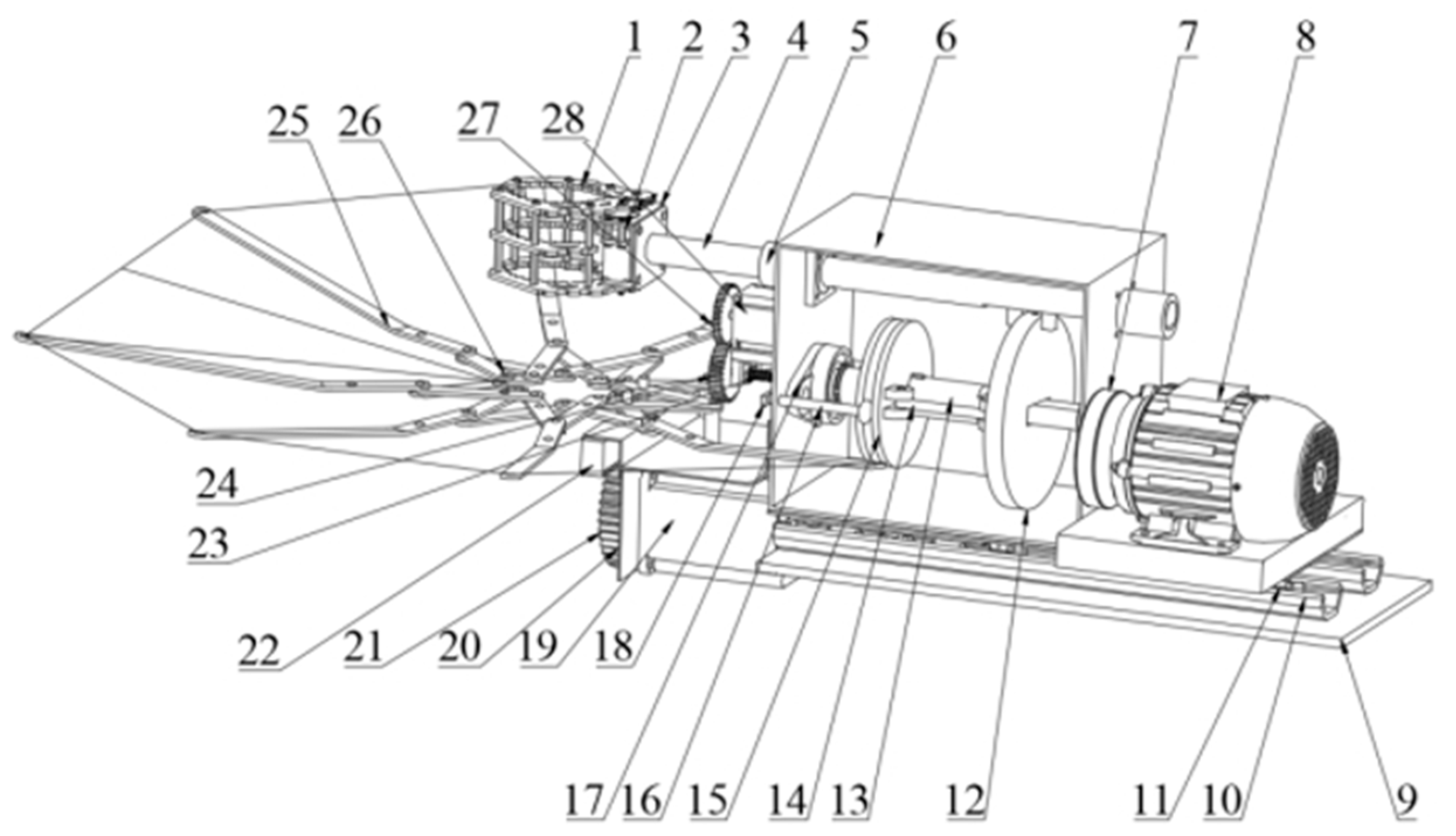
Figure 1. The vibration harvesting device of red jujube. 1. Clamping jaws; 2. Servo; 3. Clamping jaw frame; 4. Vibration rod; 5. Linear beaning; 6. Device frame; 7. Belt drive mechanism; 8. Frequency modulation motor; 9. Device base; 10. Slide rail; 11. Rail pulley; 12. Vibrating dial; 13. Driving shaft; 14. Connecting rod; 15. Amplitude modulation dial; 16. Push rod; 17. Diamond bearing; 18. Push rod frame; 19. Fruit collection motor; 20. Fruit collection frame; 21. Fruit collection gear; 22. Fruit collection rack; 23. Filament rod; 24. Amplitude modulation driven gear; 25. Umbrella bone; 26. Umbrella frame; 27. Amplitude modulation active gear; 28. Amplitude modulation motor.
Agriculture 13 01334 g001
Figure 2. A structure diagram of a red jujube vibrating device based on adjustable amplitude and frequency. 1. Vibrating rod; 2. Linear bearing; 3. Device frame; 4. Driven wheel; 5. Frequency modulation motor; 6. Active wheel; 7. Drive belt; 8. Drive shaft; 9. Vibrating dial; 10. Connecting rod; 11. Amplitude modulation dial; 12. Push rod; 13. Diamond bearing; 14. Push rod frame; 15. Filament rod; 16. Amplitude modulation driven gear; 17. Amplitude modulation active gear; 18. Amplitude modulation motor.
Agriculture 13 01334 g002
Figure 3. Structure diagram of the excitation mechanism. A is the crank; B is the slider; C is the linkage.
Agriculture 13 01334 g003
Figure 4. The movement analysis diagram of the excitation mechanism. A is the crank; B is the slider; C is the linkage; 1 represents component 1; 2 represents component 2; 3 represents component 3; 4 represents component 4.
Agriculture 13 01334 g004
Figure 5. Simulation of excitation mechanism based on ADAMS2018 software. 1. Vibrating rod; 2. Linear beaning; 3. Device frame; 4. Diamond bearing; 5. Amplitude modulation dial; 6. Drive shaft.
Agriculture 13 01334 g005
Figure 6. Fruit collection mechanism of red jujube. (a) Schematic diagram of the fruit collection mechanism of red jujubes. 1. Umbrella surface; 2. Umbrella bone; 3. Umbrella frame; 4. Fruit collection gear; 5. Fruit collection rack; 6. Fruit collection motor; 7. Fruit collection frame. (b) Structure sketch of red jujube fruit collection mechanism.
Agriculture 13 01334 g006
Figure 7. Collision model between fruit and collection device.
Agriculture 13 01334 g007
Figure 8. Grid division model of fruit collection mechanism. (a) Umbrella bone meshing; (b) Umbrella frame meshing.
Agriculture 13 01334 g008
Figure 9. Simulation of fruit collecting mechanism based on ADAMS2018 software, where Key points 1–7 are each key point of the fruit collection mechanism.
Agriculture 13 01334 g009
Figure 10. Test experiment of excitation mechanism.
Agriculture 13 01334 g010
Figure 11. Test experiment of fruit collection mechanism. (a) Fruit collection mechanism open; (b) Fruit collection mechanism closure.
Agriculture 13 01334 g011
Figure 12. Simulation displacement change curve of vibration rod.
Agriculture 13 01334 g012
Figure 13. Simulation results of vibration rod. (a) Vibration rod speed variation curve; (b) Vibration rod acceleration variation curve.
Agriculture 13 01334 g013
Figure 14. The cloud maps of displacement, strain and stress of the umbrella bone and frame. (a) Displacement cloud of umbrella bone; (b) Strain cloud of umbrella bone; (c) Stress cloud of umbrella bone; (d) Displacement cloud of umbrella frame; (e) Strain cloud of umbrella frame; (f) Stress cloud of umbrella frame.
Agriculture 13 01334 g014
Figure 15. Displacement curve of key points of fruit collection mechanism.
Agriculture 13 01334 g015
Figure 16. Simulation results of key points of fruit collection mechanism. (a) Speed variation curve of key point of fruit collection mechanism; (b) Acceleration variation curve of key point of fruit collection mechanism.
Agriculture 13 01334 g016
Table 1. Parameters in the structure diagram of the excitation mechanism.
SymbolsMeaningUnit
l 1 Vector of component 1m
l 3 Vector of component 3m
l 4 Vector of component 4m
S 1 Length of component 1m
S 3 Length of component 3m
S 4 Length of component 4m
θ 1 The tilt angle of component 1rad
θ 4 The tilt angle of component 4rad
ω 1 Angular velocity of component 1rad/s
Table 2. Displacement, strain and stress values of umbrella bone and frame.
Part NameTotal Displacement (mm)Strain (×10−4 mm)Stress (Mpa)
MaximumMinimumMaximumMinimumMaximumMinimum
Umbrella Bone13.4630.0009.6603.349 × 10−11163.5703.373 × 10−10
Umbrella Frame0.3160.0004.0415.767 × 10−680.8239.925 × 10−6
Table 3. Test results of the excitation mechanism.
Diameter Range (mm)Diameter (mm)Total Weight of Vibration Fall Jujubes (kg)Total Weight of Unvibrated off Jujubes (kg)Net Harvesting Rate
(%)
Average Net Harvesting Rate (%)Standard Deviation (%)
29.15–31.2629.1623.77 1.5293.9993.98 0.57
30.1221.64 1.2594.54
31.2620.41 1.4493.41
49.56–52.3449.5626.65 1.4594.8494.71 0.49
50.2326.65 1.6594.17
52.3429.11 1.4995.13
65.23–73.2565.2332.88 2.3593.3394.33 0.87
70.8536.21 1.9594.89
73.2537.33 2.0694.77
Table 4. Test results of the fruit collection mechanism.
Diameter Range (mm)Diameter (mm)Total Weight (kg)Total Collection Weight (kg)Collection Efficiency (%)Average Collection Efficiency (%)Standard Deviation (%)
29.15–31.2630.1221.64 20.51 94.78 95.78 1.00
29.1623.77 23.00 96.77
31.2620.41 19.55 95.78
49.56–52.3449.5626.65 23.92 89.74 89.43 0.86
50.2326.65 24.01 90.10
52.3429.11 25.75 88.46
65.23–73.2565.2332.88 27.80 84.56 85.04 1.58
70.8536.21 30.33 83.76
73.2537.33 32.40 86.80
Disclaimer/Publisher’s Note: The statements, opinions and data contained in all publications are solely those of the individual author(s) and contributor(s) and not of MDPI and/or the editor(s). MDPI and/or the editor(s) disclaim responsibility for any injury to people or property resulting from any ideas, methods, instructions or products referred to in the content.