Article

Design of Double-Roller Anisotropic Force-Feeding Device for the D200 Single Screw Straw Fiber Extruder

1
College of Engineering, Northeast Agricultural University, Harbin 150030, China
2
Heilongjiang Province Technology Innovation Center of Mechanization and Materialization of Major Crops Production, Harbin 150030, China
*
Author to whom correspondence should be addressed.
Agriculture 2023, 13(3), 670; https://doi.org/10.3390/agriculture13030670
Submission received: 23 February 2023 / Revised: 6 March 2023 / Accepted: 9 March 2023 / Published: 13 March 2023
(This article belongs to the Section Agricultural Technology)

Abstract

:
A force-feeding device with a double-roller anisotropic was designed for the D200 single screw straw fiber extruder to keep the performance continuity of the system, which could improve the productivity of straw fiber. Four factors (the diameter of the auxiliary roll, the difference in linear speed of the two rolls, the gap between two rollers and the spindle speed as the test factors) were investigated to establish regression model to analyze the influence of the coupling of multiple factors on the test indexes. It was demonstrated that significant effects (p < 0.05) on the feeding rate and material loss were produced by four factors according to the experimental results. The sequence of influence in descending order on feeding rate was spindle speed, linear speed difference, gap and auxiliary roller diameter. The effects on materials loss in descending order were auxiliary roller diameter, line speed difference, spindle speed and gap. The optimal combination of parameters was obtained by the response surface, which were an auxiliary roller diameter of 230 mm, a spindle speed of 104.49 rpm, a line speed difference of 2840 mm/s and a gap between the two rolls of 14 mm. The average feeding rate was 2.3798 t/h, and the loss was 1.908 kg/h, and the errors were within 3.28%, which satisfied the feeding requirements for rice straw fiber production with high feeding efficiency and low raw material losses. This study provided a reference for the forced compression feeding and fibrillation process of rice straw.

1. Introduction

By covering the surface of farmland, plastic mulching has been widely applied, which could increase grain yield by improving the microenvironment to promote the utilization of water and fertilizer [1,2]. Mulch film produced with crop straw is a new pollution-free and completely biodegradable mulch, which is similar to traditional plastic mulch in terms of moisture retention, temperature regulation and increasing crop yield [3]. Thus, straw mulch film may be an alternative to plastic film.
The raw material for straw mulch film was obtained by straw pulping. Referring to the traditional papermaking process, pulping methods include physical methods (mechanical grinding treatment [4] and steam blasting [5]), chemical methods (acid treatment [6], alkali treatment [7], ionic liquid treatment [8], organic solvent treatment and oxidation treatment), biological methods [9], coupling methods [10,11], etc. Based on the solid conveying theory [12,13,14], Haitao Chen et al. developed a D200 straw fiber making machine, which is composed of a single-screw extrusion system, steam explosion structure and cooling system, to pulp the crop straw without pollution. The straw is crushed by the single screw and then puffed by the steam explosion structure to increase the fiber branches [15,16], which is an effective physical pulping preparation method.
Due to the tubular structure with soft and coarse morphology, straw has more specific physical characteristics such as easy entanglement and poor mobility [17]. Thus, crop straw often accumulates at the feeding inlet of the single-screw fiber extractor to interrupt the pretreatment process [18], which not only reduces the efficiency of fiber production but also wastes a large amount of raw material during the production process. A proper feeding method is required to keep the stability and efficient operation of the system. The most common feeding method in engineering is free feeding, which relies on frictional traction of the material [19]. Liu Huanyu et al. [20] conducted combination experiments to optimize the best operating combination parameters of a D200 straw fiber extractor, and the free feeding method of raw material was used in this experiment. During feeding process, the frictional force between the single screw and the straw was not sufficient to break the arch structure of the straw accumulating at the feeding inlet. The force-feeding method is another usually used in industries, which needs extra force to assist in feeding the raw materials into the devices. Referring to the principle of the anisotropic partial engagement double-screw extruder, a double-roll feeding mechanism was designed to serve the purpose of breaking the material arch structure and achieving positive conveying [21]. By performing continuity analysis of the processes of mixing, melting and conveying the isotropic meshing double-screw extrusion expander, Ge xunyi et al. [22] derived the optimal process parameters for the preparation of straw-containing aquafeed. Cao Xinlin et al. [23] investigated the movement properties of mash at different speeds of anisotropic meshing double-screws with Pro-E and ANSYS. Yang Tao et al. [24] designed a differential double screw kneader to study the feeding, mixing and kneading process of high viscosity materials under differential velocity field.
Based on the D200 single screw straw fiber extruder and rice straw as the research object, a force-feeding device was designed with an auxiliary roller to improve the feeding speed and reduce the loss. In addition, orthogonal rotation combination experiments involving four factors and five levels were performed to determine the best combination of process parameters to meet the high-efficiency and low-loss fiber preparation work effect.

2. Materials and Methods

2.1. D200 Single Screw Straw Fiber Extruder

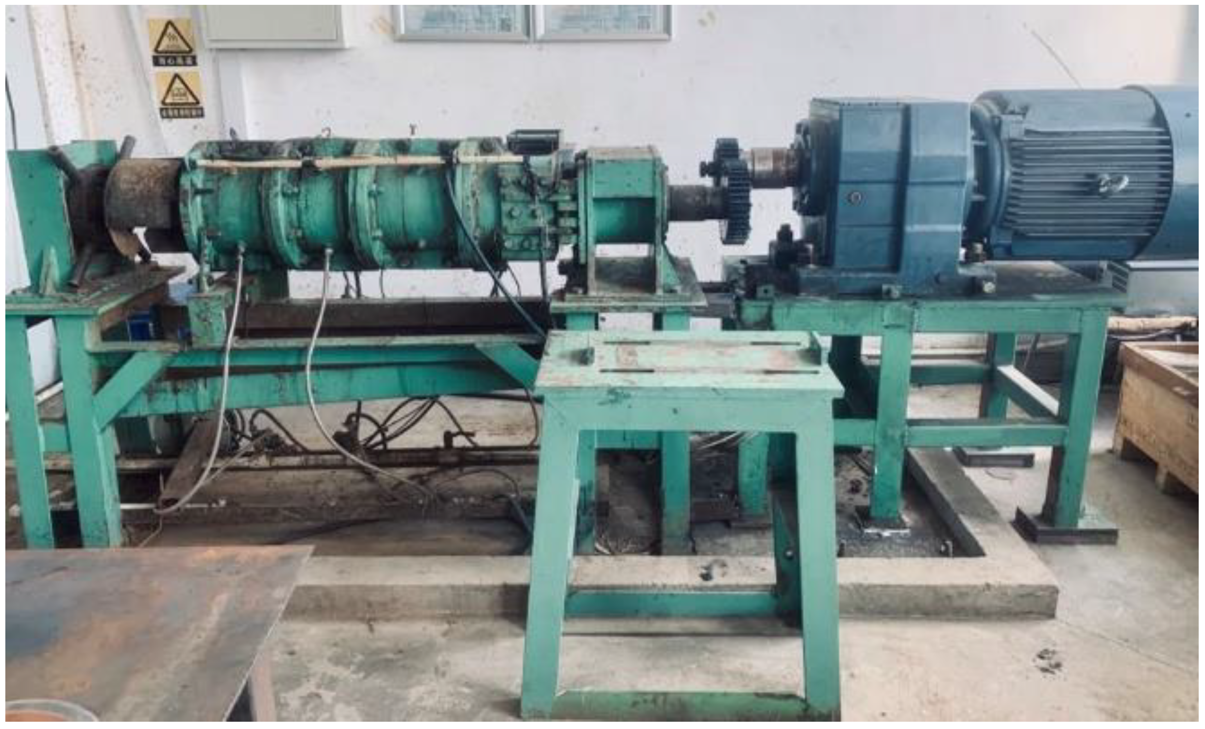
As shown in Figure 1, the D200 single screw straw fiber extruder, which was developed by the authors, was used in experiments. Four working areas were operated through with straw going from feed inlet to outlet, i.e., feeding section, compression section, shearing section and blasting section. After soaking in normal temperature water, the straw was fed into the device through the feeding inlet and then was compressed with a compression ratio of 3:1, which is convenient for crushing in the shearing section. At last, the straw was puffed in the blasting section, which would yield more straw branches. The double-roller feeding inlet is a starvation feeding device, which can adapt to different lengths and different feeding methods of straw feeding. For different feeding methods, not all affect the experimental results.

2.2. Force-Feeding Device

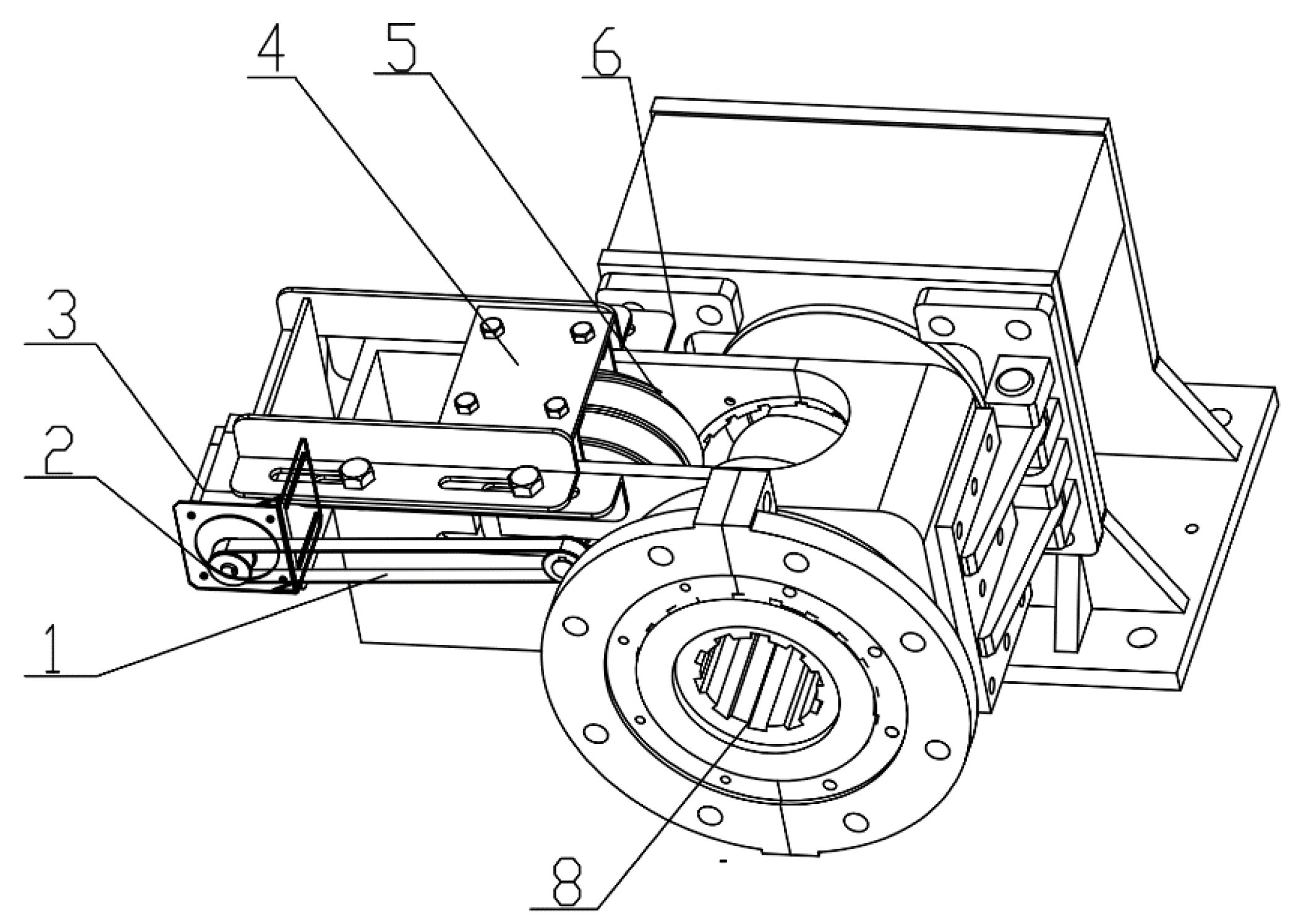
By supplying extra force on the straw, the force-feeding device, which is located in the feeding section of the D200 single screw straw fiber extrude, is used to cooperate with the single screw to solve the problems of entanglement and bridging for keeping stabilization and continuation of the feeding process. According to anisotropic double-screw structure, the force-feeding device is designed as shown in Figure 2, which is composed of an auxiliary roll, gap adjustment device, transmission system and frame. With an auxiliary roll driven by a motor, the straw was brought to the gap between the auxiliary roll and the single strew with opposite rotation of the two rolls, which was promoted by the frictional forces between straw and the two rolls. With the help of the screw axial thrust, the compressive straw would move forward to the extrusion machine.

2.3. Mechanical Analysis and Kinematics Analysis of Straw

2.3.1. Kinematics Analysis

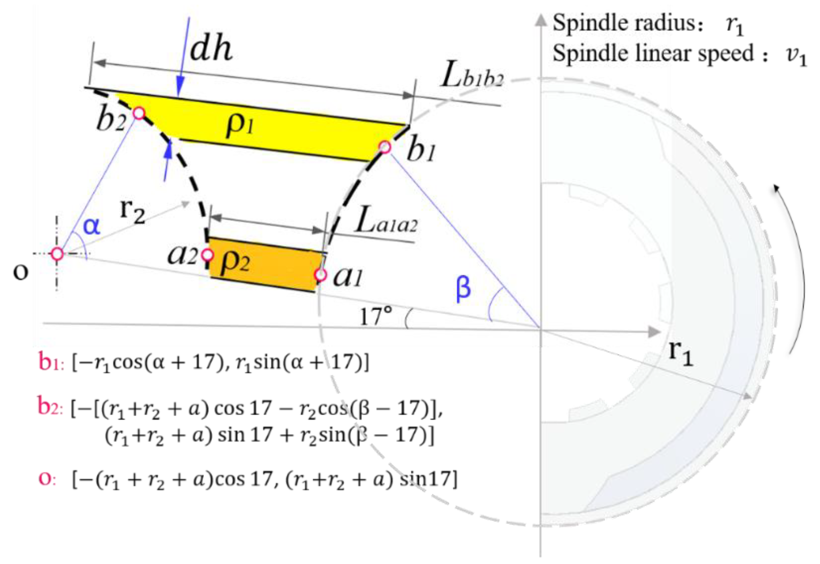
As shown in Figure 3, assuming that the gap between the two rolls in the cross-section (perpendicular to the axial direction of the single screw) was always filled with straw, the straw filled in micro-elements with height dh, which would be compressed with density moving from p1 to p2, while ignoring the change in height. The geometric relations of structure parameters were also calculated.
By assuming no loss of straw during the compression process, the mass of straw in the two dh areas should be the same as the law of conservation of mass, as shown in Equation (1).
ρ 1 b L d h = ρ 2 a L d h
where L is Y-directional length of the force-feeding device; a and b are the gap length between two rollers, respectively.
The deformation degree of the straw directly was influenced by the pressure force and frictional force from the screw spindle and the auxiliary roll, which were affected by the geometric characteristics of the auxiliary roll diameter and the gap between the roller and the spindle. In this study, the compression ratio γ was used to characterize the degree of straw compression. The initial position of the straw micro-element in the spindle and auxiliary roll contact point was set as b1(x1, y1), b2(x2, y2), and its length was Lb1b2. After Δt time, the straw was moved to the coordinates of a1(x1′, y1′) and a2(x2′, y2′), which could be calculated with Equations (2)–(7), and the compression ratio γ was described by Equation (8).
θ 1 = v 1 r 1 Δ t × 180 ° π
θ 2 = s v 1 r 2 Δ t × 180 ° π
a 1 = r 1 cos a + 17 θ 1 , r 1 sin α + 17 θ 1
a 2 = r 1 + r 2 + a r 1 cos 17 r 2 cos β θ 2 , r 1 + r 1 + a sin 17 r 2 sin ( β θ 2 )
L b 1 b 2 = x 2 x 1 2 + y 2 y 1 2
L a 1 a 2 = x 2 x 1 2 + y 2 y 1 2
γ = 0 α 0 β L b 1 b 2 L a 1 a 2 d α d β
where θ 1 is angle of spindle side rotation in Δt(°); θ 2 is angle of roll side rotation in Δt(°); v 1 is spindle line speed; s is line speed difference; α is maximum turning angle of roller side; β is maximum turning angle of spindle side.

2.3.2. Mechanical Analysis

As shown in Figure 4, the forces (pressure forces and frictional forces from two rollers) acting on the straw in the gap were described. To ensure success of passing through the gap, the resultant forces in the negative direction of the Z-axis should be greater than 0, which were described by the Equation (9) as follows:
F x F + F f 1 cos α F N 1 sin α F N 2 sin β F f 2 cos β 0 M O F f 1 cos α a 2 F N 1 sin α b 2 F N 2 sin β b 2 F f 2 cos β b 2 0
where F is active pressure on the straw; FN is positive pressure of two round rollers; Ff is frictional force; α is side angle of spindle; β is side angle of the roller.
From the above formula, it can be obtained that:
F + 2 F f 1 cos α 2 F N 1 sin α 0
To ensure that the material can move downward in the gap, the friction force must be less than the maximum static sliding friction:
F f 1 F N 1 μ 1 F f 2 F N 2 μ 2
Substituting it into the Equation (10):
μ 1 tan α F 2 F N 1 cos α
If the extra pressure force acting on straw was 0, the pressure forces and frictional forces from two rollers could be calculated with Equations (13)–(16):
F N 1 = G sin α + 17 + cos α + 17 sin β 17 cos β 17
F N 2 = G sin α + 17 + cos β 17 sin α + 17 cos α + 17
F f 1 = μ 1 G sin α + 17 + cos α + 17 sin β 17 cos β 17
F f 2 = μ 2 G sin α + 17 + cos β 17 sin α + 17 cos α + 17
where μ 1 is the coefficient of static friction between the material and the stainless steel; μ 2 is the coefficient of static friction between the material and the rubber.

2.4. Auxiliary Roller

The diameter of the auxiliary roll and the gap between the two rollers were important parameters affecting the feeding process. Based on the kinematic analysis mentioned above, the ratio of the density between the initial feeding state and the ultimate feeding state was chosen to calculate the compression ratio, i.e.,
γ = ρ 2 ρ 1 = b a
The screw radius r1 is 100 mm.
h = r 1 sin α = 51.5   mm
sin β 51.5 r 2 r 2 51.5   mm
b = r 2 r 2 cos β + a + r 1 r 1 cos α
where h is height before and after compression; r1 is diameter of the screw spindle; r2 is diameter of the auxiliary roll.
The compression ratio could be described as Equation (21).
γ = a + 14.3 + r 2 r 2 2 51.5 2 a
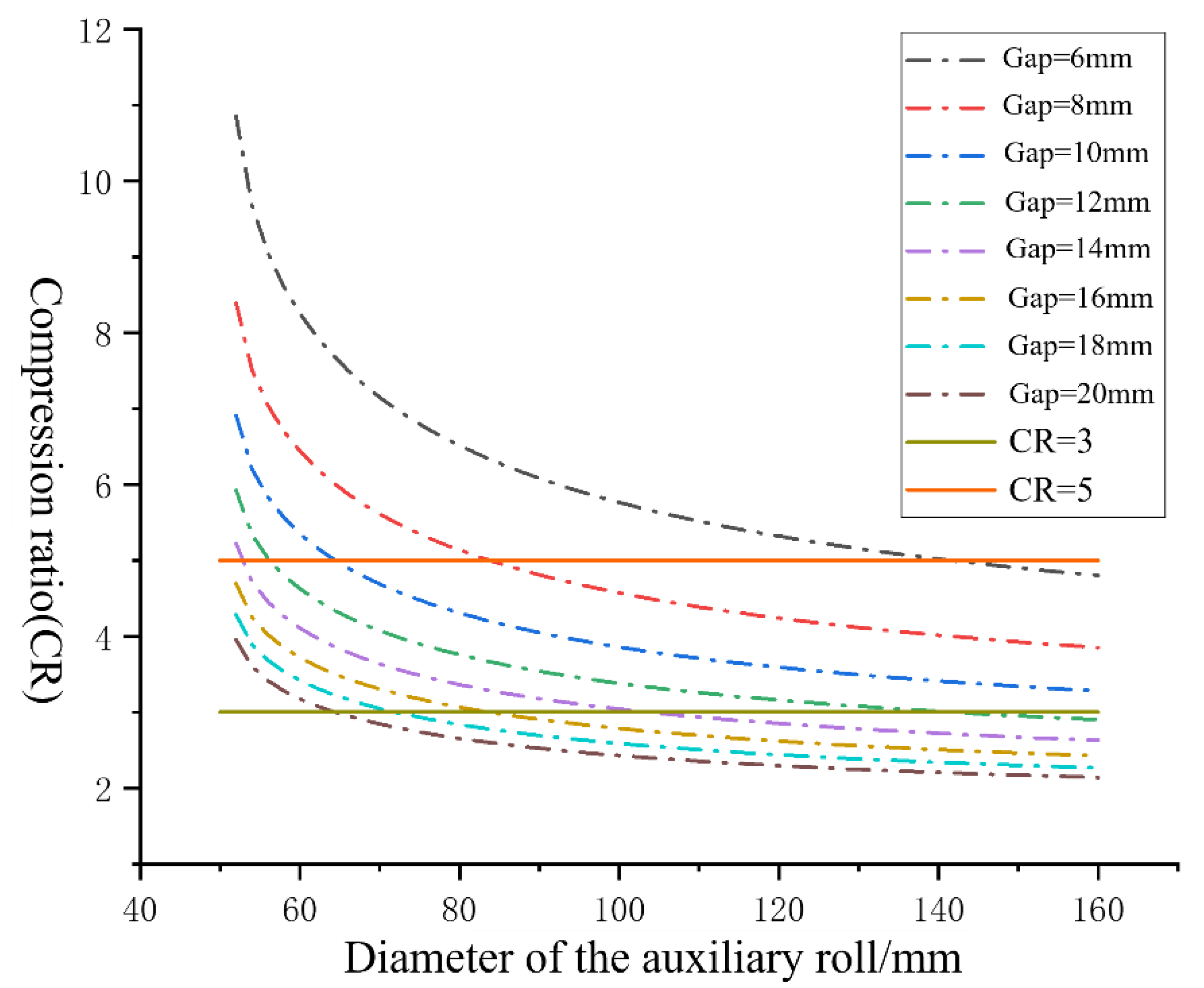
The relationship of the compression ratio and the diameter of auxiliary roller can be obtained according to Equation (21), as shown in Figure 5. The compression ratio measured in experiments of the feed inlet and outlet of the device was about 3. In this study, the compression ratio was set to 3–5, i.e., 3 γ 5 , and the gap between the two rolls was set as 6–12. The radius r2 was calculated [51.5, 151.5].

2.5. Spindle Speed

The spindle speed of the D200 straw fiber making machine directly would affect the conveying performance and the shear rate of system [24]. With an increase in the spindle screw speed, the straw near the spindle screw side in the force-feeding device was dragged into system more easily, which increased the feeding rate of the material until a certain value. However, the quality of the fiber would decrease with increasing spindle speed. Based on previous research, the spindle speed was selected as 85–105 rpm to keep the feeding rate of the force-feeding device and the fiber quality.

2.6. Line Speed Difference

In the feeding process, difference between the auxiliary rollers and the spindle causes the straw in the gap to be fed into the system by frictional forces, which increases the feeding rate and leads to straw losses. To keep a high feeding efficiency and low loss, a 3 × 3 orthogonal simulating test was designed with EDEM2018 software to optimize the best speed difference, as shown in Figure 6. The physical parameters of straw were listed in Table 1; the diameter of the screw spindle is 200 mm, and the gap is 11 mm.
A pellet sphere was used to establish the model of rice straw with a 70 mm length. The Hertz was applied to establish the bonding between the straw pellet spheres by considering the bending deformation of rice straw during the feeding process. The radius of pellet sphere was 2.5 mm, and the adhesion radius was 3 mm.
In this study, a straw length of 70 mm and saturated water content were selected, and spindle speed was set to 85 rpm, 100 rpm and 115 rpm, respectively. Then, the line speed differences of 2000 mm/s, 4000 mm/s and 6000 mm/s were selected for an orthogonal comparison test. The efficiency and loss rate of rice straw transported under different spindle speed and line speed differences were investigated. The simulation results are shown in Table 2.
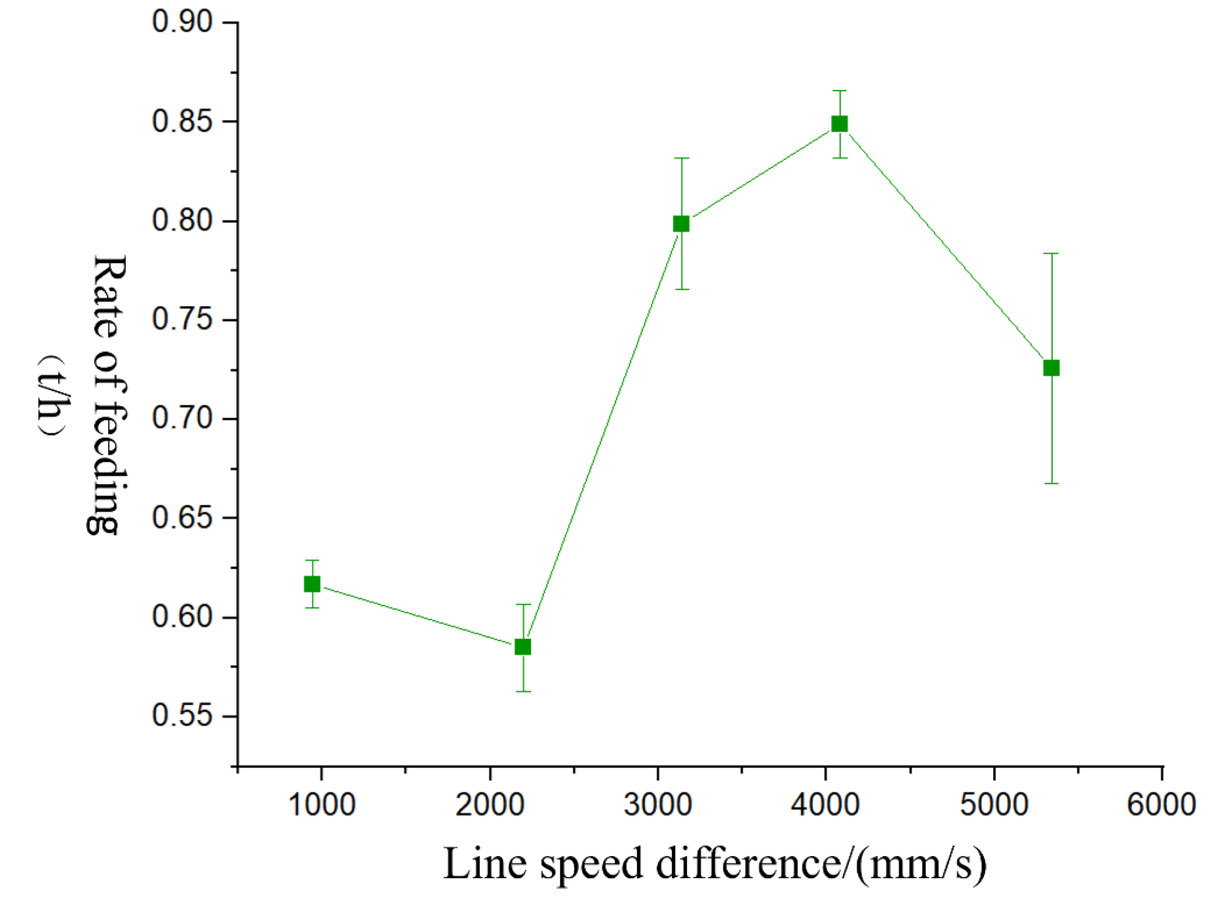
From the simulation result, it can be deduced that the accumulation phenomenon of straw in the gap could be eased effectively with increasing the line speed difference, but a high line speed difference will lead to more losses as short straw is pulled out. When the spindle speed was 85 rpm and when the line speed difference was 6000 mm/s, the maximum loss rate was 25.2%. For verifying the simulation result, the single factor test was performed, and the influence curve of line speed difference on feeding rate was shown in Figure 7. From the experimental results, the performing parameters were obtained with a line speed difference of 4000 mm/s, which has the largest feeding rate and lowest loss rate. It was similar to the simulation results and provides a basis for the selection of the optimal process parameters.
The test results show that many small straws are wrapped and pulled by the winding characteristic of actual test materials, which increases the feeding rate and also causes the error of discrete element simulation. As shown in Figure 8, the winding property of rice straw enhances the feeding effect and reduces the loss rate. At the line speed difference of 4000 mm/s, the feeding rate is the largest, and the loss rate is the lowest, which is similar to the simulation results and provides a suggestion for the optimal of process parameters.

2.7. Experimental Materials and Equipment

In this study, rice straw from Suixian No.9, Suilan County, Suihua City, was selected as the test material. Before the test, rice straw was soaked in normal temperature water for 8 h to reach saturated moisture content.
The D200 straw fiber making machine made by Northeast Agricultural University was used in the experiments. The test instrument adopts the ATV312HU75N4 inverter, Schneider Electric Co., LTD., frequency conversion range of 0~50 Hz; 6SE6440-2UD33-71B137KW inverter 0~60 Hz; ACS-30 electronic scale, Yongkang Jiangnan Weighing Instrument Factory, measuring range 30 kg, accuracy 10 g; Supo blast drying oven, Shaoxing Super Instrument Ltd., temperature control range 50 °C~300 °C; and a vernier caliper with an accuracy of 0.1 mm.

2.8. Experimental Design

A quadratic orthogonal rotating center combination method was designed with four factors and five levels. The diameter of the auxiliary roll, the line speed difference between the roller and the spindle, the spindle speed and the gap between the two rolls were selected as test factors. The diameter of the auxiliary roll X1 was 170–230 mm; the line speed difference X2 was 2000–4000 mm/s; the spindle speed X3 was 85–105 r/min; and the gap X4 was 8–14 mm. The test factor coding table was shown in Table 3.

2.9. Detection Method

The average feeding rate of the force-feeding device was an important factor affecting the efficiency of straw fiber making. By selecting three points within a 9-min time frame, recording the feeding amount of straw in 3 min, and calculating the feeding rate recorded as Y11, Y12 and Y13, in turn, each group of tests was repeated three times, and the final result was taken as the mean value of the three tests.
Y 1 = M t
where M was the amount of feeding; t was the feeding time.
Fiber loss Y2 was used to evaluate the force-feeding effect of the force-feeding device of the D200 fiber mill by measuring the residual straw.

3. Results

3.1. Experimental Results

The experimental protocol and the results of the 36 groups of tests were shown in Table 4.

3.2. Regression Model and Variance Analysis

The variance analysis results of the feeding rate and loss of the feeding device were shown in Table 5. The model term was significant (p < 0.01) at the significance level α = 0.05, indicating that the model selection was appropriate, and the misfit term was not significant (p > 0.05). Based on the regression analysis data in Table 3, a comprehensive evaluation equation of multiple test factors on feeding rate and amount of loss was established. In the regression model of feeding rate device, the interaction items X1 X2 and X1 X4 and items X12 and X22 for the diameter of the auxiliary roll and gap were insignificant (p > 0.05). In the loss volume regression equation, the interaction terms X1 X2, X2 X3 and X3 X4 and items X12, X22 and X32 were insignificant (p > 0.05). Eliminating the insignificant parameters, the regression equation of feeding rate and loss index of the force-feeding device were established.
Y 1 = 1.63 + 0.063 X 1 + 0.11 X 2 + 0.19 X 3 + 0.073 X 4 + 0.045 X 1 X 3 0.12 X 2 X 3 + 0.042 X 3 X 4 + 0.071 X 3 2 0.037 X 4 2
Y 2 = 0.032 + 3.164 X 1 + 4.747 X 2 + 4.164 X 3 + 4.914 X 4 + 2.747 X 1 X 3 2.747 X 1 X 4 + 3.247 X 2 X 4 2.414 X 4 2
The contribution of each factor to the performance index was explored through the variance analysis of regression model. By comparing the F value, it was concluded that the influencing sequence of each parameter on the feeding rate was spindle speed, line speed difference, gap and diameter of the auxiliary roll. While the order of influence of each parameter on the amount of loss was gap, line speed difference, spindle speed and roller diameter.

4. Discussion

4.1. Interaction on Feeding Rate of the Force-Feeding Device

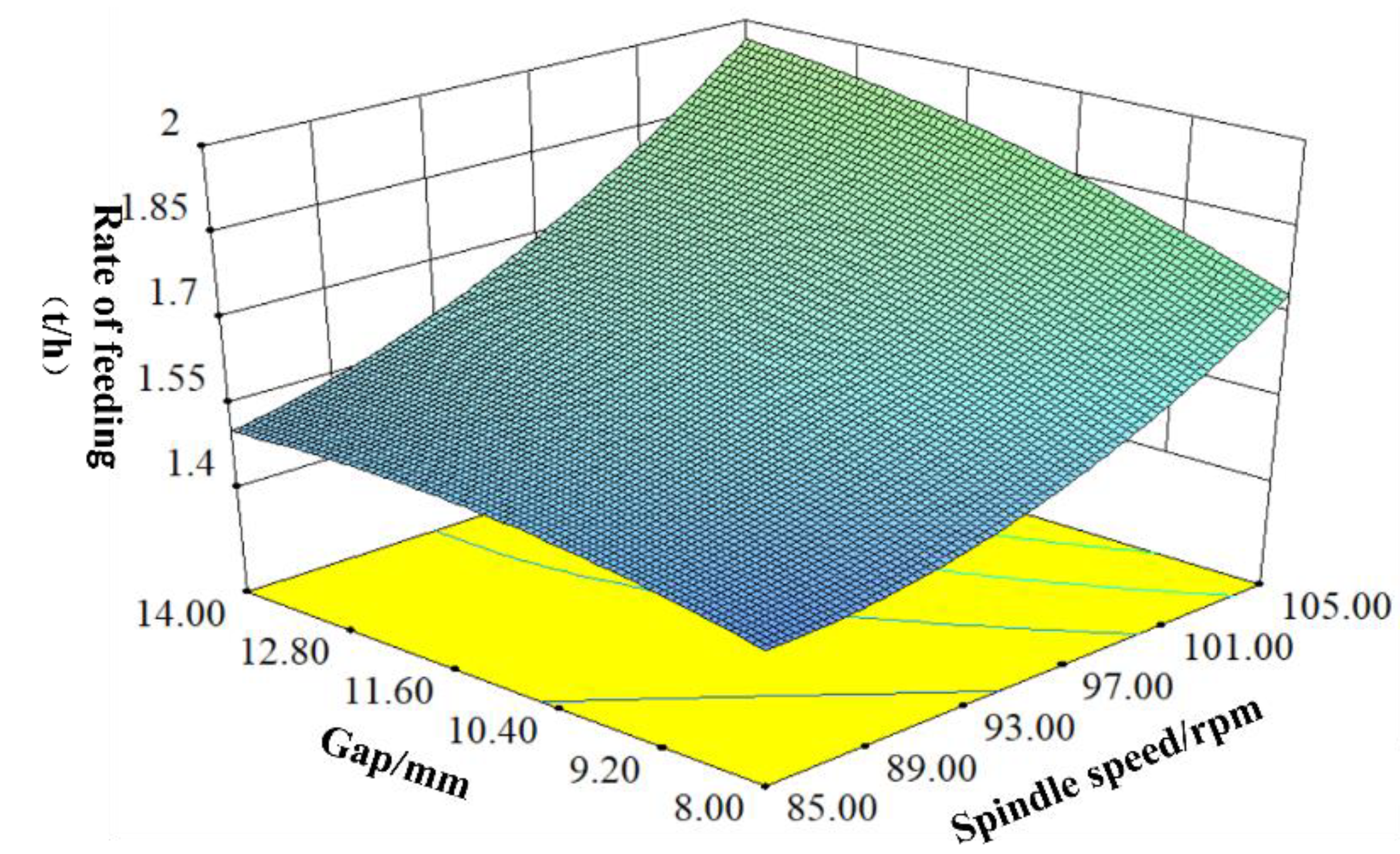
With the diameter of the auxiliary roll of 200 mm and the line speed difference of 3000 mm/s, the interaction between the gap and between the two rolls and the spindle speed of the machine on the feeding rate of the force-feeding device was shown in Figure 9. When the spindle speed is smaller than 93 m/s, the feeding rate does not change significantly with the increase in the gap between the two rolls, which is about 1.500 t/h. With the spindle screw speed increasing, the increasing trend of the feeding rate increases with the increase in the gap between the two rolls, which is from 1.714 t/h to 1.960 t/h. On the other hand, the feeding rate increases with the increase in the spindle screw speed and shows a slow growth trend with the increase in the gap between the two rolls. The straw transportation in the fiber-making machine relies on the spiral thrust and frictional force generated by straw, so higher spindle speed would promote the movement of materials in system, which leads to the higher feeding rate.
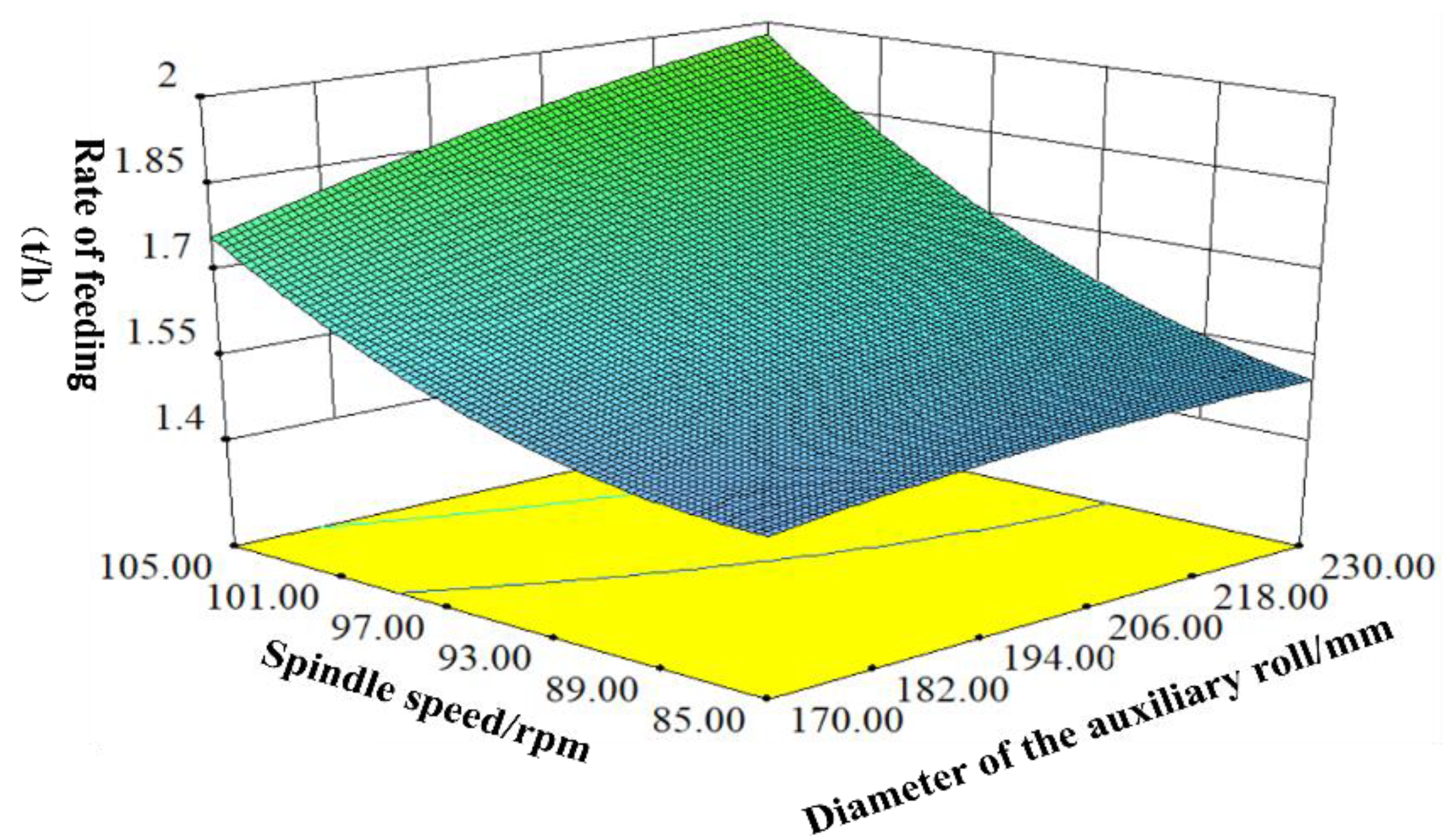
When the line speed difference was 3000 mm/s and when the gap between the two rolls was 11 mm, the interaction of gap between the two rolls and line speed difference on the feeding rate was shown in Figure 10. As can be seen from the figure, the feeding rate increases with an increase in spindle speed. With the diameter of auxiliary roll increasing, the contact area between the auxiliary roll and the rice straw increases, which provides more frictional force for the material, so the feeding rate of the force-feeding device would increase significantly.
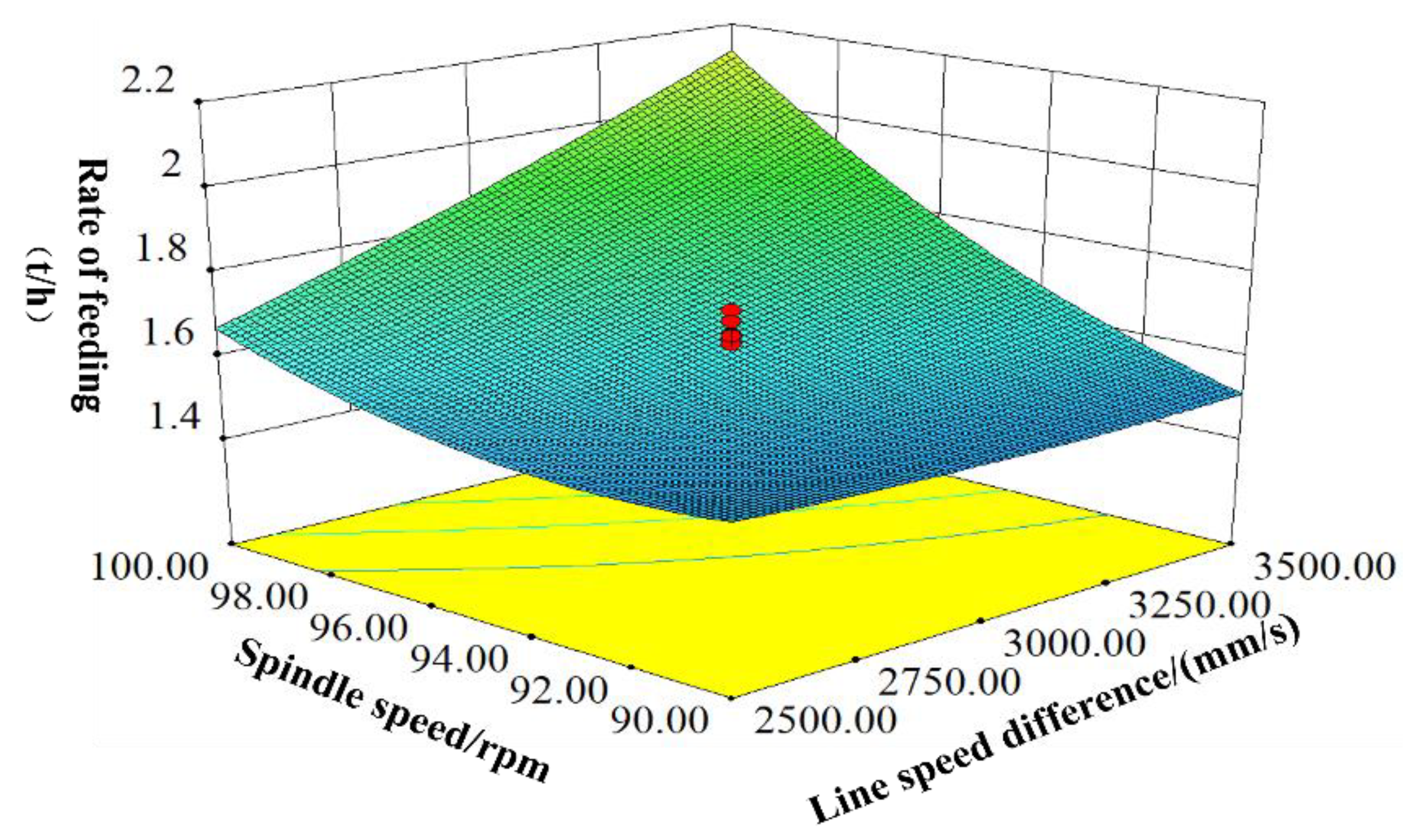
When the diameter of the auxiliary roll was 200 mm and when the gap between the two rolls was 11 mm, the interaction between spindle speed and the line speed difference on the feeding rate of the device was shown in Figure 11. The feeding rate of the force-feeding device increases with the increase in spindle speed and the line speed difference, and the max value was 2.100 t/h. With a low line speed difference and a line speed difference, the feeding rate does not change significantly; this is because the system could not supply more power to push straw forward with low parameters. Thus, with an increase in line speed difference, it provides a higher traction frictional force for the straw to raise the increasing trend of feeding rate. With the increase in spindle speed, the straw is fed quickly as there is a powerful traction force generated by straw, which effectively avoids the feeding resistance caused by the accumulation of material in the gap, so the feeding rate grows significantly.

4.2. Effect of Interaction on Loss of Force-Feeding Device

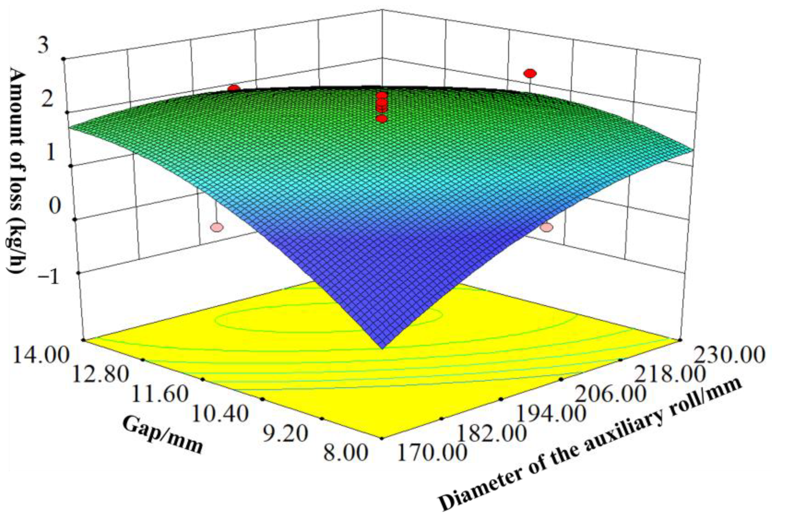
With the spindle speed of 95 rpm and the line speed difference of 3000 mm/s, the interaction of the diameter of the auxiliary roll and the gap between the two rolls on the material loss was shown in Figure 12. With a small diameter of the auxiliary roll, the loss of material increases with the increase in the gap between the two rolls, which changes from 0.60 kg/h to 1.86 kg/h. However, with the diameter of the auxiliary roll enlarging, the growth trend slows down; a reversal trend was approaching when the diameter of the auxiliary roll was 194 mm, and the amount of loss shows a decreasing trend with the increase in gap. With a larger diameter of the auxiliary roll, the initial contact area and contact angle of the material with rollers would increase, resulting in the enlargement of the frictional force between the straw and the rollers, which improves the feeding patency of straw. Meanwhile, the volume between two rollers was also enlarged. Thus, the loss was reduced.
With a spindle speed of 95 rpm and a diameter of the auxiliary roll of 200 mm, the interaction between the line speed difference and the gap between the two rolls on material loss was shown in Figure 13. With low values of the line speed difference and gap, the loss of materials undulated up and down, which was not significant. With the values of parameters increasing, the amount of loss showed a significant upward trend, and the max value was 3.63 kg/h. When the roll diameter and spindle screw speed were constant values, the line speed difference was larger, and the auxiliary roll rotational speed was larger, which resulted in short straw being thrown easily out of the gap, so the growing trend of loss is more significant.
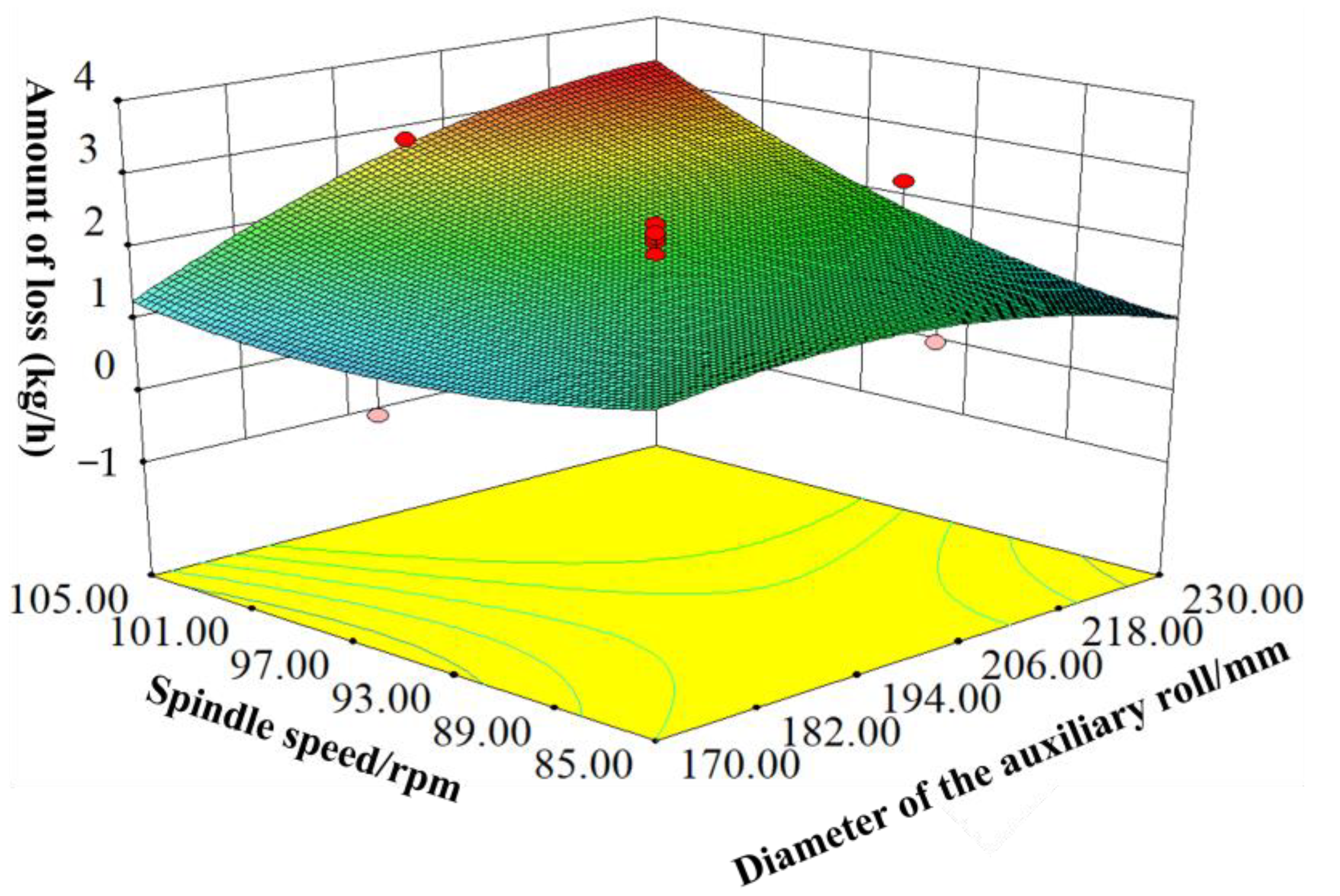
When the gap between the two rolls was 3 mm and when the line speed difference was 3000 mm/s, the interaction between the diameter of the auxiliary roll and the spindle speed on material loss was shown in Figure 14. With a low value of the diameter of the auxiliary roll and spindle speed, the loss of materials fluctuates between 1.50 kg/h and 1.80 kg/h. With increasing values of two parameters, the loss increases, and the max value was about 3.32 kg/h. If the line speed difference were a constant value, the diameter of auxiliary roll changed with its rotational speed. As shown in Figure 6, the compression rate of straw decreases as the diameter of the auxiliary roll increases, which leads to the slippage of pressure and frictional force acting on straw from two rollers. The straw was thrown more easily out of the gap than the small diameter of the auxiliary roll. With increasing spindle speed, more and more straw were fed into the compression segment, so the amount of straw loss also increased with the increase in the diameter of the auxiliary roll.

4.3. Parameter Optimization

To keep high efficiency, low loss and operation continuity of straw fibrosis treatment, a high feeding rate and low material loss were selected as the optimization goals, and four parameters of spindle speed, gap between the two rolls, auxiliary roll speed and line speed difference were optimized to obtain the parameter combination. The feeding rate prediction optimization model of the force-feeding device was established as follows [25].
max y 1 = f X 1 , X 2 , X 3 , X 4 min y 2 = f X 1 , X 2 , X 3 , X 4 X 1 2 , 2 X 2 2 , 2 X 3 2 , 2 X 4 2 , 2
After optimizing, as shown in Figure 15, the feeding rate of the D200 fiber making machine and the loss were 2.449 t/h and 1.974 kg/h, respectively, with a diameter of the auxiliary roll of 230 mm, a spindle speed of 104.49 rpm, a line speed difference of 2840 mm/s and a gap between the two rolls of 14 mm.

4.4. Verification Experiment

To verify the parameter optimizing results, the spindle speed of 104.49 rpm, diameter of the auxiliary roll of 230 mm, line speed difference of 2840 mm/s and gap between the two rolls of 14 mm were selected as the performance parameters, and the experimental results with an average of 5 were shown in Table 6. The results were similar to the theoretical optimized values with the relative error within 3.28%. Therefore, it is reasonable a performance of the D200 straw fiber making machine with the optimized parameters.

5. Conclusions

(1) The parameters of spindle speed, gap between the two rolls, diameter of the auxiliary roll and line speed difference have a highly significant effect on the feeding rate and loss of the D200 fiber making machine force-feeding device (p < 0.01). The influencing sequence of each parameter on the feeding rate of the device is spindle speed, line speed difference, gap and diameter of the auxiliary roll, while the order of influence of each parameter on the amount of loss is gap, line speed difference, spindle speed and roller diameter. This starvation feeding device provides a design reference for the further collection, processing and treatment of agricultural waste with saturated moisture content that is prone to entanglement.
(2) In this paper, optimization of the performance parameters of the D200 straw fiber making machine according to the requirements of a high feeding rate and low loss is demonstrated. With a diameter of the auxiliary roll of 230 mm, a line speed difference of 2810 mm/s, a gap between the two rolls of 14 mm and a spindle speed of 104.53 rpm, the average feed rate of the fiber making machine unit was 2.419 t/h, and the loss rate was 1.944 kg/h, which could achieve the purpose of continuous performance of the fiber making system with a high feeding rate and low loss. It can provide a process reference for the fibrous production, high value utilization and feed processing of agricultural crop straw.

Author Contributions

Conceptualization, L.L., C.Z. and C.G.; methodology, L.L., C.Z. and C.G.; software, C.G. and S.F.; writing-original draft preparation, L.L. and C.Z.; writing-review and editing, C.Z. and X.W.; project administration, W.J., L.L. and H.C. All authors have read and agreed to the published version of the manuscript.

Funding

The Special Fund Project for the Construction of a Modern Agricultural Industrial Technology System (Grant No. CARS-04) and the Natural Science Foundation Youth Fund of China (Grant No. 31701311).

Institutional Review Board Statement

Not applicable.

Data Availability Statement

The data presented in this study are available on request from the corresponding author.

Acknowledgments

Thanks to the “Natural Science Foundation Youth Fund of China” for the financing of this research.

Conflicts of Interest

The authors declare no conflict of interest.

References

  1. Liu, G.; Zuo, Y.; Zhang, Q.; Yang, L.; Zhao, E.; Liang, L.; Tong, Y. Ridge-furrow with plastic film and straw mulch increases water availability and wheat production on the Loess Plateau. Sci. Rep. 2018, 8, 6503. [Google Scholar] [CrossRef] [PubMed] [Green Version]
  2. Nelson, T.F.; Remke, S.C.; Kohler HP, E.; McNeill, K.; Sander, M. Quantification of synthetic polyesters from biodegradable mulch films in soils. Environ. Sci. Technol. 2020, 54, 266–275. [Google Scholar] [CrossRef] [PubMed]
  3. Li, S.; Ding, F.; Flury, M.; Wang, Z.; Xu, L.; Li, S.; Jones, D.L.; Wang, J. Macro-and microplastic accumulation in soil after 32 years of plastic film mulching. Environ. Pollut. 2022, 300, 118945. [Google Scholar] [CrossRef] [PubMed]
  4. Yin, D.; Wu, M.; Li, D. Microstructure and creep properties of ultramicronized corn stover with straw-starch blended film. J. Agric. Mach. 2016, 47, 297–304. [Google Scholar]
  5. Liu, H.; Chen, H.; Hou, L.; Zhang, Y. Optimization Design and Experiment of Raw Material Supply System for D200 straw fibre making machine. Trans. Chin. Soc. Agric. Mach. 2017, 48, 92–98. [Google Scholar]
  6. Shen, F.; Wang, Q.; Li, Y.; Li, X.; Hu, J. Hydrothermal sulfite pretreatment of chrysanthemum straw with highly concentrated substrate enzymatic hydrolysis test. J. Agric. Mach. 2014, 45, 168–173. [Google Scholar]
  7. Zhang, H. Study on Preparation of Regenerated Cellulose Film from Fine Components of Corn Straw Pulping by Alkaline Method. Ph.D. Thesis, Kunming University of Science and Technology, Kunming, China, 2019. [Google Scholar]
  8. Yang, Y. Study on Pretreatment of Straw with Ionic Liquid/Low Eutectic Solvent and Its Mechanism. Ph.D. Thesis, University of Chinese Academy of Sciences (Institute of Process Engineering, CAS), Beijing, China, 2021. [Google Scholar]
  9. Guo, J.; Guo, Y.; Zhao, Q.; Wu, S.; Dong, R. Effects of fungus solid carrier pretreatment on degradation of non-sterilized corn straw. Trans. Chin. Soc. Agric. Mach. 2016, 47, 197–202. [Google Scholar]
  10. Aravinth, K.; Ramakrishnan, T.; Tamilarasan, V.D.; Veeramanikandan, K. A brief review on plant fibres composites: Extraction, chemical treatment and fibre orientation. Mater. Today Proc. 2022, 62, 2005–2009. [Google Scholar] [CrossRef]
  11. Dhali, K.; Daver, F.; Cass, P.; Adhikari, B. Isolation and characterization of cellulose nanomaterials from jute bast fibers. J. Environ. Chem. Eng. 2021, 9, 106447. [Google Scholar] [CrossRef]
  12. Mi, C.Q.; Mclean, A.G.; Arnold, P. Optimal mechanical design of single span screw feeders. Powder Handl. Process. J. 1991, 3, 227–239. [Google Scholar]
  13. Haaker, G.; Jongejan, M.; Bekhuis, J. A method to optimize screw feeder geometry for equable draw-down performance. Powder Handl. Process 1994, 6, 209–214. [Google Scholar]
  14. Roberts, A. The influence of granular vortex motion on the volumetric performance of enclosed screw conveyors. Powder Technol. 1999, 104, 56–67. [Google Scholar] [CrossRef]
  15. Roberts, A.W.; Willis, A.H. Performance of Grain Augers. Proc. Inst. Mech. Eng. 1962, 176, 165–194. [Google Scholar] [CrossRef]
  16. Chen, H.; Miao, N.; Dong, B.; Dun, G.; Zhang, Y. Experimental study on structure optimization of D200 straw fibre making machine. J. Northeast. Agric. Univ. 2015, 46, 90–94. [Google Scholar] [CrossRef]
  17. Jin, B.; Zhang, Y.; Zhang, M.; Zhong, W.; Sun, Z. Study on the flow behavior of biomass straw in the filling hopper. J. Sol. Energy 2008, 29, 1131–1134. [Google Scholar]
  18. Chen, H.; Zhang, Y.; Huang, Z.; Fang, X.; Li, L. Effect of Moisture content on the flow dynamics characteristics of rice straw. J. Northeast. Agric. Univ. 2013, 44, 90–94. [Google Scholar]
  19. Song, G. Combined Design Study of Screw-Mesh Cold-Feed Extruder. Master’s Thesis, Qingdao University of Science and Technology, Qingdao, China, 2010. [Google Scholar]
  20. Liu, H.; Jiang, L.; Chen, H.; Xia, J.; Li, L. Working Parameters Optimization and Performance Test of Rice Straw Fiber making Machine. Trans. Chin. Soc. Agric. Mach. 2020, 51, 161–169. [Google Scholar]
  21. Zheng, X. Modular Design and Research of Spiral Meshing Cold Feed Extruder. Ph.D. Thesis, Qingdao University of Science and Technology, Qingdao, China, 2011. [Google Scholar]
  22. Ge, X. Study on the preparation of floating aquafeed containing straw based on twin-screw extrusion and expansion technology. Master’s Thesis, Yangzhou University, Yangzhou, China, 2019. [Google Scholar]
  23. Cao, X.; He, J.; Zhang, B. Numerical Simulation of Mud Extrusion Process under Different Rotating Speeds of Meshing Twin Screw. Acta Ceram. Sin. 2015, 36, 678–682. [Google Scholar]
  24. Yang, T. Screw Geometry and Computer Aided Design of Differential Twin Screw Kneader. Master’s Thesis, Chongqing University, Chongqing, China, 2006. [Google Scholar]
  25. Fan, G.; Niu, C.; Zhang, Z.; Wang, D.; Mao, W.; Jiang, H. Design and experiment of V-shaped anti-drift spraying device for multi-airflow cooperative orchard. J. Agric. Mach. 2022, 53, 138–147. [Google Scholar]
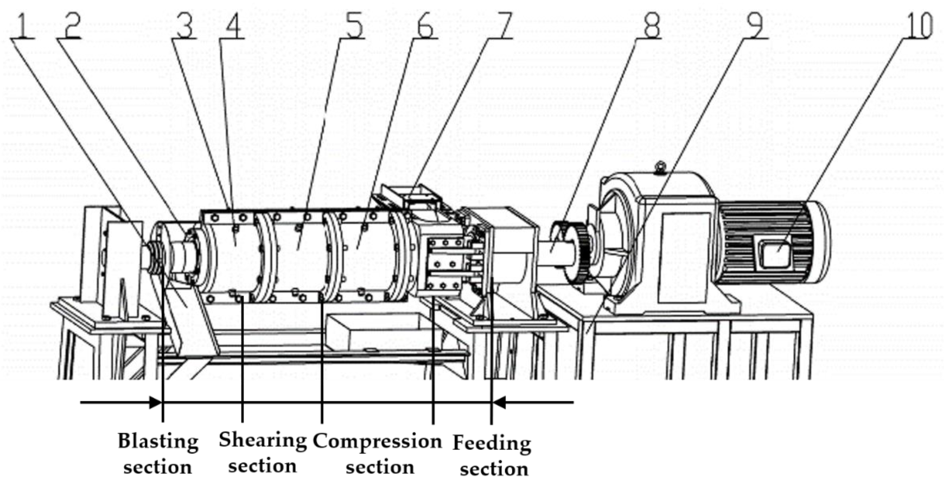
Figure 1. The structure of the D200 straw fiber making machine. 1. Discharge port; 2. Regulating die head; 3. Cooling system; 4. Blasting Section; 5. Shearing Section; 6. Compression Section; 7. Force-feeding device; 8. Spindle; 9. Frame; 10. Main motor.
Agriculture 13 00670 g001
Figure 2. Sketch of the structure of the force-feeding unit. 1. Synchronous belt; 2. Synchronous belt wheel; 3. Three-phase asynchronous motor; 4. Roller fixing frame; 5. Auxiliary roll; 6. Frame; 8. Spindle.
Agriculture 13 00670 g002
Figure 3. Kinematic analysis of straw feeding.
Agriculture 13 00670 g003
Figure 4. Analysis of straw feeding mechanics.
Agriculture 13 00670 g004
Figure 5. Compression ratios.
Agriculture 13 00670 g005
Figure 6. Simulation of the straw feeding movement process.
Agriculture 13 00670 g006
Figure 7. The result of single factor experiments.
Agriculture 13 00670 g007
Figure 8. D200 straw fiber making machine.
Agriculture 13 00670 g008
Figure 9. Influence of gap and spindle speed on feeding rate.
Agriculture 13 00670 g009
Figure 10. Influence of spindle speed and auxiliary roller diameter on feeding rate.
Agriculture 13 00670 g010
Figure 11. Influence of spindle speed and linear speed difference on feeding rate.
Agriculture 13 00670 g011
Figure 12. Influence of the gap and assist roller diameter on the amount of loss.
Agriculture 13 00670 g012
Figure 13. Influence of the gap and linear velocity difference on the amount of loss.
Agriculture 13 00670 g013
Figure 14. Influence of spindle speed and auxiliary roller diameter on the amount of loss.
Agriculture 13 00670 g014
Figure 15. Parameters optimizing results.
Agriculture 13 00670 g015
Table 1. Physical parameters.
ParametersValue
Poisson’s ratio0.4
The density of rice straw241 kg/m−3
Shear modulus of straw1 × 106 Pa
Coefficient of recovery between straw0.357
Coefficient of static friction between straw0.44
Coefficient of dynamic friction between straw0.55
Straw-component recovery coefficient0.23
Straw-component static friction factor0.363
Straw-component dynamic friction factor0.465
Table 2. Orthogonal simulation test results.
Spindle Speed (rpm)Line Speed Difference/(mm/s)Feeding Rate/(t/h)Rate of Loss/%
8520000.36317.3
40000.45918.2
60000.43625.2
10020000.47512.7
40000.52414.1
60000.49921.4
11520000.5129.4
40000.65711.8
60000.53517.3
Table 3. Factor levels coding of central composite experiment.
LevelExperimental Factors
Diameter of the Auxiliary Roll X1/(mm)Line Speed Difference X2/(mm/s)Spindle Speed X3/(r/min)Gap X4/(mm)
+2230400010514
+1215350010012.5
020030009511
−11852500909.5
−21702000858
Table 4. Results of central composite experiments.
No.Experimental FactorsTest Index
Diameter of Rollers X1Line Speed Difference X2Spindle Speed X3Gap X4Feeding Rate Y1Amount of Loss Y2
1200.0300095.011.001.5880.028
2200.0300095.011.001.6130.03
3200.0400095.011.001.8830.045
4230.0300095.011.001.6670.037
5185.02500100.012.501.5190.029
6215.0350090.09.501.4440.023
7215.02500100.09.501.730.034
8200.0300095.011.001.6430.031
9200.0300095.011.001.6540.029
10200.0300095.011.001.7130.028
11200.0300095.08.001.3280.01
12200.0300095.011.001.4650.025
13200.0300095.011.001.5970.036
14215.0350090.012.501.5370.032
15200.0300095.011.001.6550.039
16185.02500100.09.501.4950.022
17200.03000105.011.002.3440.047
18200.0300085.011.001.5040.026
19215.0250090.012.501.5260.024
20185.0250090.009.501.4320.018
21185.03500100.012.502.1730.039
22185.0350090.09.501.4280.017
23185.0250090.012.501.4650.025
24170.0300095.011.001.4580.01
25215.02500100.012.501.6170.031
26200.0300095.014.001.6580.032
27215.03500100.012.502.4490.049
28200.0300095.011.001.6320.03
29215.03500100.09.501.9750.04
30200.0300095.011.001.6870.032
31200.0300095.011.001.6520.037
32185.0350090.012.501.4570.054
33200.0200095.011.001.5050.027
34185.03500100.09.501.6730.031
35215.0250090.09.501.4630.024
36200.0300095.011.001.6140.035
Table 5. Variance analysis of regression models.
Source of VariationQuadratic SumDegree of FreedomMean SquareF-Valuep-Value
Y1 Model1.98140.1422.59<0.0001
Residual0.13216.250
Lack of fit0.089108.8842.30.0936
Error0.042113.8552.30
Sum2.1135
Y2 Model2.686141.9166.97<0.0001
Residual5.783212.751
Lack of fit3.816103.8152.140.1145
Error1.963111.783
Sum3.26435
Table 6. Experimental results with optimized parameters.
TitleFeeding Rate/(t/h)Amount of Loss/(kg/h)
Experimental results2.3662.016
2.2941.746
2.4132.046
2.4471.734
2.3792.004
Average value2.37981.908
Optimized value2.4491.974
Relative error rate2.83%3.28%
Disclaimer/Publisher’s Note: The statements, opinions and data contained in all publications are solely those of the individual author(s) and contributor(s) and not of MDPI and/or the editor(s). MDPI and/or the editor(s) disclaim responsibility for any injury to people or property resulting from any ideas, methods, instructions or products referred to in the content.