Article

Efficacy of Sweet Potato Transplanting Machine for Different Cultivation Systems in Northern China

1
Shandong Academy of Agricultural Machinery Sciences, Jinan 250100, China
2
Shandong Academy of Agricultural Sciences, Jinan 250100, China
3
Huang Huai Hai Key Laboratory of Modern Agricultural Equipment, Ministry of Agriculture and Rural Affairs, Jinan 250100, China
*
Author to whom correspondence should be addressed.
Agriculture 2022, 12(8), 1184; https://doi.org/10.3390/agriculture12081184
Submission received: 12 July 2022 / Revised: 31 July 2022 / Accepted: 5 August 2022 / Published: 9 August 2022

Abstract

:
China is the world’s biggest producer of sweet potato (Ipomoea batatas (L). Lam.), and approximately 55% of the global supply is from China. Raised beds (RB) and raised beds mulched with plastic film (RBF) are the two main sweet potato cultivation systems now widely used in northern China. Planting placement of multiple nodes buried in shallow soil layers is additionally required for the sweet potato cultivation to achieve higher yields and reduce pests and diseases in this area, which increases the difficulty of transplanting mechanically. Therefore, a 2CGFS-2 compound sweet potato transplanter was developed, and the key parameters of slips transplanting apparatus were designed in this paper. Furthermore, its performance was investigated over two years under four treatments with different sweet potato varieties (Jishu 26 and Pushu 32) and cultivation systems (RBF and RB). The results showed that the missing seedling rate and qualified rate of transplanting population for each treatment by using 2CGFS-2 compound transplanter were <1.2% and >95.0% in both 2020 and 2021, while the mean values of the plant spacing variation coefficient and the qualified rate of transplanting depth during 2020–2021 were 4.53% and 96.28%, respectively. The length of the sweet potato slip inserted into the soil by the 2CGFS-2 compound sweet potato transplanter was almost the same, ca. 195 mm. The accurate placement of the sweet potato slips reduced the differences in tuber weight per plant caused by manual transplanting. These results are of considerable importance for RB and RBF sweet potato cultivation systems.

1. Introduction

Sweet potato (Ipomoea batatas (L). Lam.) is a very important agricultural crop that is rich in carbohydrates and can serve as a source of protein, carotenoid, vitamin C, K, E, several B vitamins and fibers [1,2]. These vitamins play an essential role in the immune function and are known to lower the susceptibility to infections [3]. According to Food and Agriculture Organization (FAO) statistics, China is the world’s biggest producer of sweet potato [4], and approximately 55% of the global supply is from China [5]. Since sweet potato has wide ecological adaptation, strong tolerance to drought and low requirements for soil fertilizer [6], it is widely planted over half of the nation’s poor counties. According to the multiplicity and complexity of climatic conditions, cultivation systems and soil conditions, sweet potato cultivation areas in China are generally divided into three areas: the northern China area, Yangtze River area, and southern China area [7].
The Northern China area is formed by the north of Huai river and includes the regions of Hebei, Henan, Shandong, Shanxi, Anhui, Liaoning, Beijing, Tianjin, etc. This area has a monsoon climate with annual average temperature, frost free period, sunshine percentage and annual rainfall of 8~15 °C, 150~250 days, 45~70%, and 450~1100 mm, respectively [8]. According to the data of the National Bureau of statistics, the planting area of sweet potato in this region is about 841 kha (24.5% of the whole country), and the yields amount to 28.1% of the total sweet potato production in China [9]. Traditionally, farmers planted sweet potatoes on mounds to improve the infiltration of water and the penetration of roots in this area [10]. At present, sweet potato is customarily cultivated on raised beds in northern China, which is a characteristic of mechanized production [7]. Furthermore, many studies have found that cultivation on raised beds mulched with plastic film (RBF) may be detrimental to sweet potato yield because it improves soil water moisture, soil bulk density, and soil porosity compared with conventional cultivation by reducing runoff and soil evaporation, as well as increasing infiltration and water storage [11,12,13]. Thus, RBF and raised beds (RB) are the two main sweet potato cultivation systems nowadays widely used in northern China [14,15].
A number of transplanting machines have been developed to plant vegetable-potted seedlings on RBF and RB systems in several parts of the world [16]. Checchi & Magli Transplanters used perforating cup to transplant vegetable seedlings [17]. Revolving spades were developed by Holland Transplanter for the mulch transplanter [18]. Ferrari Construzioni Meccaniche Srl developed a series of film transplanters to accomplish film-laying and seedling-transplanting simultaneously in one pass [19]. Liu et al. [20] used the duck-billed transplanting mechanism with planetary five-bar to plant potted tomato seedlings. In general, the above researches mainly focused on studying the work performances by using perforators combined with various mechanisms to place potted seedlings vertically on RBF or RB systems, which are not applicable for sweet potato planting. Specifically, sweet potatoes are planted worldwide using bare-rooted plants (slips or vines) due to the particularity of their breeding.
As the most labor-intensive tasks in sweet potato production, planting sweet potato slips mechanically will help to alleviate the contradiction between increasing demand for sweet potato production and the decline in the labor force [21]. There were no special transplanters for sweet potato slips until Chen et al. [22] modified a commercially available transplanter for horizontal transplanting of sweet potatoes in raised beds. Hu et al. [23] improved the above type of sweet potato transplanting machine into a compound planting machine for sweet potato slips. Since the above machines have to open furrows before planting the slips, they are suitable only for the RB cultivation system. Subsequently, ISEKI & Co., Ltd. [24] (Matsuyama, Japan) designed a PVH type sweet potato transplanter for the RBF cultivation system, which worked at the speed of 0.5 km/h with only one row transplanted at a time. Moreover, multiple passes of the machines would also cause soil compaction in the long term.
In northern China, planting multiple nodes buried in shallow soil layers is additionally required for sweet potato cultivation to achieve higher yields and reduce pests and diseases [7]. Those requirements prevent direct application of transplanting machines for sweet potato cultivation. Additionally, sweet potato slips are still planted manually in the RBF and RB cultivation systems (as shown in Figure 1). Therefore, in this paper, we report the development of the 2CGFS-2 compound sweet potato transplanter and its performance in planting sweet potato slips in the RBF and RB cultivation systems in northern China, aiming at providing a useful and highly efficient transplanting machine to improve the mechanization level of sweet potato slip cultivation.

2. Design of the 2CGFS-2 Compound Sweet Potato Transplanter

2.1. Background of Agronomic Requirements for Sweet Potato Cultivation

Depending on their experience and location, farmers use various tillage methods and planting postures for sweet potato cultivation [25]. The tillage systems, which include RBF and RB, optimize infiltration and facilitate root expansion [26]. In northern China, slip placement at planting varies from vertical orientation, oblique orientation, and boat-shaped orientation to horizontal orientation (as shown in Figure 2a), to realize more nodes buried in shallow soil layers [27]. At present, the boat-shaped placement is widely used in the RBF and RB cultivation systems, since it has the advantages of labor-saving compared with horizontal placement, producing more sweet potato tubers of uniform size compared with oblique placement. Therefore, the 2CGFS-2 compound sweet potato transplanter was designed based on the agronomic requirements of boat -shaped placement in both RBF and RB cultivation systems [28].
The specific agronomic requirements of the boat-shaped orientation are as follows: strong slips with proper plant spacing (mostly from 18 cm to 30 cm according to the soil fertility and variety of sweet potato) and row spacing (80~90 cm) planted in the soil appearing as a boat. In more detail, the slip length is about 25~35 cm (including the branches and leaves), and the slip diameter is about 5 mm. Four to five slip nodes are buried in the soil while one or two slip nodes are left out of the RBF or RB system. In other words, the length of slips buried under the soil is about 10~20 cm and depends on the sweet potato variety planted. The heads and tails of slips are tilted up like the bottom of a ship. The planting depth is within the range of 5~10 cm, while the planting angle ranges from 30° to 60°.
To figure out the parameters of the compound sweet potato transplanter, we described the above requirements analytically (Formula (1)). We first assumed that the planting track formed by the movement of the transplanting mechanism was E(x, y) under the planting coordinate system XOY. As shown in Figure 2b, the track contains the following key points: soil penetration point, H (xH, yH); the excavation point, Q (xQ, yQ); the deepest point, M (xM, yM); the farthest point, N (xN, yN), and the angle between the slip and the ground, η.
{ h = y M y H h [ 50 mm , 100 mm ] Z 1 x M x H 2 + h 2 + x M x N 2 + y M y N 2 Z 1 [ 100 mm , 200 mm ] η = arctan y H x H η 30 , 60 Z 2 = x Q x H Z 2 > 0
where Z1 is the length of buried sweet potato slips (mm), Z2 is the surface disturbance length in the RB system or film breaking length in the RBF system (mm), and h is the planting depth of the slips. Here, yM = ymax(E(x,y)); xN = xmax(E(x,y)).

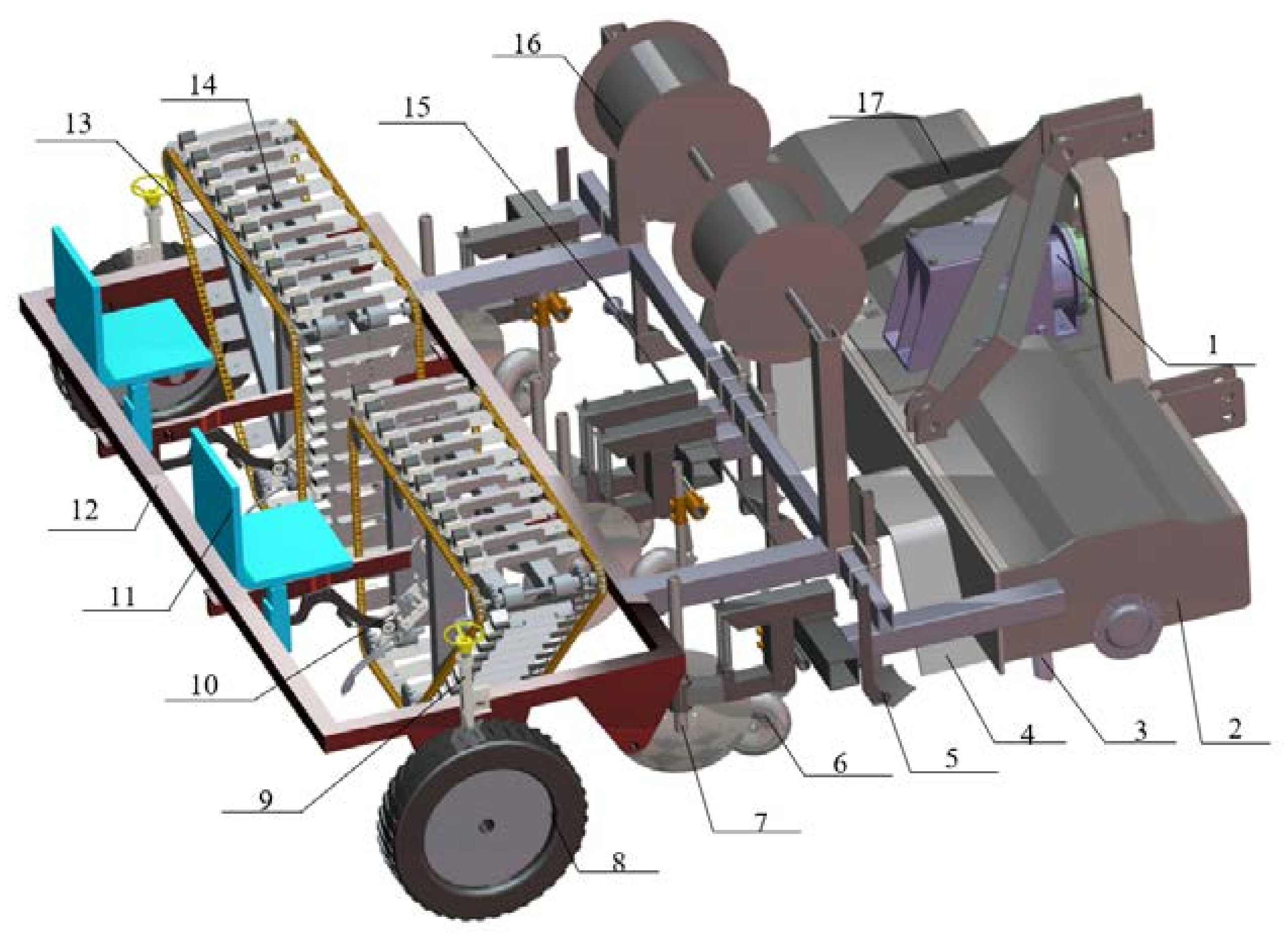
2.2. Machine Structure and Working Principle

Since the wheel track of the tractor, which has adequate horsepower to drive the transplanter, is 110~150 cm, much wider than the row spacing, it is necessary to reduce the landing times of the tractor by applying the method of multiple operation in one pass. As shown in Figure 3, the 2CGFS-2 compound transplanter for sweet potato slip cultivation is mainly composed of a rotary tillage apparatus, ridging and film mulching apparatus, and slip transplanting apparatus. It can complete land preparation, ridging, film mulching, drip-irrigation belt laying and transplanting on two ridges at one time. All of the working processes are carried out in the RBF system, while the processes of film mulching and drip-irrigation belt laying are unused in the RB system. As shown in Figure 3, the main components of the rotary tillage apparatus are a transmission box, side soil sealing plate, and rotary tillage component. Additionally, the main components of the ridging and film mulching apparatus are a plastic-film frame, ridge board, ridge opener, film pressing wheel, and soil covering disc, while the slip transplanting apparatus consists of a driving ground wheel, height adjustment mechanism, seedling taking and planting mechanism, transmission system, slip delivery mechanism, etc.
During the mechanized operation of sweet potato slip planting in RBF or RB systems, the tractor hangs the 2CGFS-2 compound transplanter through the three-point hitch system. The rotary component completes the soil crushing and soil preparation operations by high-speed rotation driven by power from the transmission box, which is connected with the power take off (PTO) of the tractor. Then, the ridge board squeezes the crushed soil to form two rows of trapezoidal ridges with a height of 30 cm under the traction of the tractor and the pressure of the hydraulic cylinder simultaneously. In particular, the ridging opener and film pressing wheel are used to mulch the ridge in the RBF system, which is then covered by soil. As the most important working process, the slip transplanting apparatus clamps and plants the slips on the ridge in the RBF or RB system through the seedling taking and planting mechanism, which is driven by the ground wheel. In more detail, slips are manually placed in the seedling delivery mechanism by the operators sitting on the seats.

2.3. Slips Transplanting Apparatus

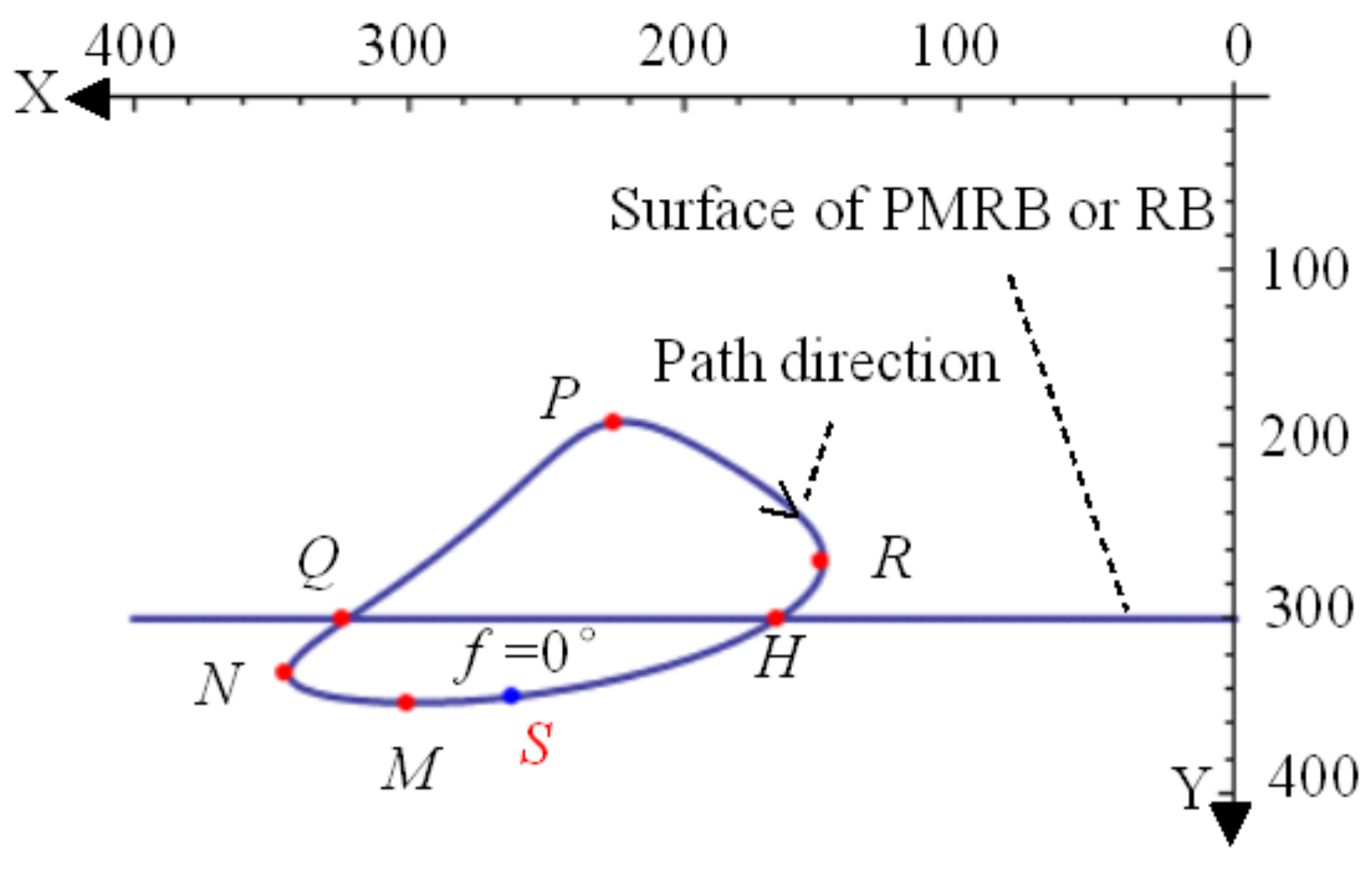
2.3.1. Slips Taking-Planting Mechanism

As one of the most key functional units of the slip transplanting apparatus, the slip taking-planting mechanism is composed of crank rocker assembly and seedling clamping assembly (Figure 4a). The crank rocker assembly contains a frame, crank, connecting rod, rocker, etc., and the seedling clamping assembly consists of a driving cam, clip finger, guide rail, etc., which in the working process would be installed on the connecting rod through a bracket. Its operating principle is consistent with the existing finger clip planting assembly [24], while the key parameters are designed based on the requirement (Formula (1)) for boat-shaped slip placement in northern China.
The schematic model of the slip taking-planting mechanism was built to determine the key structural parameters that affected slip placement. As shown in Figure 4b, XOY, consistent with the coordinates in the agronomy requirements in Figure 2b, was the planting coordinate when the mechanism is planting the sweet potato slips. More specifically, the X axis and Y axis are parallel and vertical to the ground, respectively, and their positive directions are opposite to the forward direction and downward to the ground. According to the geometric relationship, the slip trajectory E(x, y) is expressed as follows:
x = x A + l 1 cos φ 0 + φ + l 5 cos θ + φ 0 + δ   y = y A + l 1 sin φ 0 + φ + l 5 sin θ + φ 0 + δ   φ 0 , 2 π
Here,
δ =   arccos l 2 2 + d 2 l 3 2 2 l 2 d β
β = arcsin l 1 sin φ d
d = l 1 2 + l 4 2 2 l 1 l 4 cos φ
According to the established conditions for the crank rocker assembly [29], the above variables should meet the following constraints (Equations (6) to (11)):
g 1 l 2 , l 3 , l 4 , l 5 , θ = l 1 < 0
g 2 l 2 ,   l 3 , l 4 ,   l 5 , θ = l 1 + l 4 l 2 l 3 0
g 3 l 2 ,   l 3 , l 4 ,   l 5 , θ = l 1 + l 2 l 3 l 4 0
g 4 l 2 ,   l 3 , l 4 ,   l 5 , θ = l 1 + l 3 l 2 l 4 0
g 5 l 2 ,   l 3 , l 4 ,   l 5 , θ = 30 ° arccos l 2 2 + l 3 2 l 4 l 1 2 2 l 2 l 3 0
g 6 l 2 ,   l 3 , l 4 ,   l 5 , θ = arccos l 2 2 + l 3 2 l 4 + l 1 2 2 l 2 l 3 150 ° 0
Assuming that the crank length l1 is fixed, we analyzed the relationship between the planting trajectory and other parameters for different decision variables. As shown in Figure 5, the variation of l2 affected the overall shape of the planting trajectory, which directly determined the planting placement pattern. Additionally, the change in l4 had an effect on the area enclosed by the planting trajectory, which was related to the disturbance extent of the soil or mulched film and the slip length buried in the RBF or RB soil. On the other hand, φ0 was proportional to the soil penetration angle η, while l3, l5, and θ also had a slight impact on the planting trajectory.
We assumed that the angle between the working rod and the connecting rod θ = 0°, xA = 0 mm, yA = 0 mm. Then, the variables were l2, l3, l4, l5, φ0. According to the agronomic planting experience and requirements, the clip finger was arranged to form a non-coincident loop track E(x, y) (Figure 6) to prevent the slip placement from being affected by the mechanical or manual planting movement. Thus, we further determined the proportional relationships for the crank rocker assembly by referring to the analysis of the four-bar linkage [30], as shown below:
l1:l2:l3:l4:l5 = 1:(2.0~2.5):(1.5~4.0):(2.5~4.5):(2.0~4.0)
According to Formula (2), the first derivative of the planting trajectory E(x, y) with respect to φ is as follows:
{ x = l 5 l 1 l 4 sin φ d l 2 l 1 l 4 e sin φ 2 d 3 l 2 1 e 2 4 d 2 l 2 2 + l 1 cos φ d l 1 2 l 4 sin 2 φ d 3 1 l 1 2 sin 2 φ d 2 × sin θ + arccos e 2 d l 2 : arcsin l 1 sin φ d l 1 sin φ y = l 1 cos φ + l 5 cos θ + arccos e 2 d l 2 arcsin l 1 sin φ d × l 1 l 4 sin φ d l 2 l 1 l 4 e sin φ 2 d 3 l 2 1 e 2 4 d 2 l 2 2 l 1 cos φ d l 1 2 l 4 sin 2 φ d 3 1 l 1 2 sin 2 φ d 2
where e = l 1 2 + l 2 2 l 3 2 + l 4 2 2 l 1 l 4 cos φ = l 2 2 l 3 2 + d 2 .
In order to prevent interference between the slip taking-planting mechanism and the slip delivery mechanism and ensure the slips are taken by the clip finger above the soil surface, the slips were designed to be taken at the nearest point R of the planting trajectory. In addition, the point C on the connecting rod of the crank rocker assembly (Figure 4) was also above the soil surface. Those restrictions were formulated as follows (Equations (14) to (16)):
g 7 l 2 ,   l 3 , l 4 ,   l 5 , θ = x R x H < 0
g 8 l 2 ,   l 3 , l 4 ,   l 5 , θ = l 5 l 2 > h
g 9 l 2 ,   l 3 , l 4 ,   l 5 , θ = l 4 sin φ 0 + l 3 y M h < 0
where xR = xmin(E(x,y)).
According to Equations (2), (12) and (13), the coordinates and polar coordinate parameters of the farthest planting point N and the nearest planting point R would be calculated when x′ = 0, while the coordinate parameters of the uppermost point P and the deepest point M would be obtained when y′ = 0. Besides that, the coordinate parameters of penetrating point H and unearthed point Q would also be determined when y = yMh.
In order to determine the optimal parameter combination, we first set the initial value and solution interval of the decision variables according to Formula (12). Then, the constrains from g2(l2, l3, l4, l5, φ0) to g6(l2, l3, l4, l5, φ0) (Equations (2) and (11)) and g7(l2, l3, l4, l5, φ0) to g9(l2, l3, l4, l5, φ0) (Equations (14) and (16))were further given. Subsequently, dozens of decision variable value groups and their relative evaluation indexes of transplanting performances, i.e., planting depth h, length of slips under the soil Z1, planting angle η and disturbance length Z2 (as shown in Formula (1)), were obtained through the solution process as shown in Figure 7. Finally, fuzzy comprehensive evaluation method [31] was used to optimize these parameters. With consideration for slip planting practices, we set the weight distribution of the planting indexes as
P1 = [0.1 0.45 0.35 0.1]
where the weights of the planting depth h, length of slips under the soil Z1, planting angle η and disturbance length Z2 were 0.1, 0.45, 0.35 and 0.1, respectively. We constructed the evaluation model based on the entropy weight-fuzzy comprehensive evaluation method, as follows:
r i j = Y i j Y i min Y i max Y i min   ( i = 1 , 2 , 3 , 4 ; j = 1 , 2 , 3 , )
R r = r 11 r 12 r 21 r 22 r 31 r 32 r 41 r 42
W = P 1 R r = [ W j ]
where Yij is the jth calculated value under the ith evaluation indicator, Yimax (Yimin) is the maximum (minimum) calculated value of the ith evaluation indicator, Rr is the evaluation criteria matrix, Wj is the jth fuzzy comprehensive evaluation value, and W is the fuzzy comprehensive evaluation value matrix.
Finally, according to the optimal fuzzy comprehensive evaluation score W1, we optimized the decision variable parameters as: l2 = 2.0l1, l3 = 2.0l1, l4 = 2.5l1, l5 = 2.75l1, φ0 = 0°. Meanwhile, the values of evaluation indicators were also calculated, i.e., the included angle η between the slip and the ground after planting was 56.2°, the planting depth h was 60mm, the length of sweet potato slips under film Z1 was 195 mm, and the soil disturbance length Z2 was 110 mm. All of the above parameters met the agronomic requirements for boat-shaped placement in RBF and RB cultivation systems in northern China.

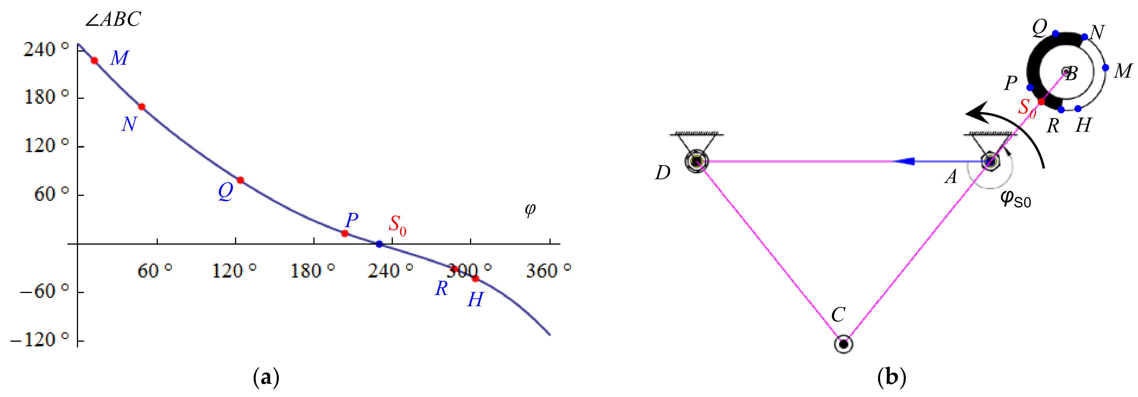
2.3.2. Working Sequence Parameters of the Slip Taking-Planting Mechanism

Besides optimization of the parameters of the crank rocker assembly, the organization of the working sequence between the crank rocker assembly and seedling clamping assembly was essential to achieve the slip taking and planting movement. As the values of decision variables were fixed, the parameters of each key point of the trajectory were determined: the penetrating point H (xH = 103.2, yH = 198.1, φH = 303.4°), the unearthed point Q (xQ = 213.6, yQ = 198.1, φQ = 123.8°), the farthest point N (xN = 282.7, yN = 244.6, φN = 48.4°), the nearest point R (xR = 93.7, yR = 171.7, φR = 287.1°), the uppermost point P (xP = 127.0, yP = 126.9, φP = 203.5°), and the deepest point M (x M = 236.7, yM = 258.1, φM = 12.0°).
The open and shut movement of the clip finger in the seedling clamping assembly was essential for the working sequence to form the boat-shape placement. To integrate the open-shut movement of the clip finger with the transplanting trajectory of the crank rocker assembly, the driving cam was designed to drive the clip finger to shut at point R and to open at point N with the sweet potato slips taken and placed, respectively.
Since no relative rotation existed between the driving cam and the crank, the angle ∠ABC between the connecting rod and the crank was equal to the angle between the roller and the driving cam in the seedling clamping assembly, and its relation with the independent variable φ was expressed as follows:
ABC = δ + π   -   φ   φ 0 , 2 π
The roller was centered around the point B, and the angle ∠ABC thus described the working sequence of the clip finger with the rotation of the independent variable φ (Figure 8a). As shown in Figure 8b, the clip finger was designed to open during φNφ < φR and to close during φRφ < φN + 2π to realize the boat-shape placement. In more detail, the clip finger was kept closed from R-H-M to N points and open from N-Q-P to R points along the transplanting trajectory. Since the initial position S0 should be better between points P and R, we determined ∠ABC = 0 as the initial position, in which the independent variable φS0 was about 230°.
A kinematics simulation analysis was carried out for the slip taking-planting mechanism to verify whether the working sequence fulfilled the matching requirements between the crank rocker assembly and seedling clamping assembly or not. We set up the crank rotating anti-clockwise in the simulation model with the initial state (φ = φS0) (Figure 9a). As shown in Figure 9b, the key points along the slips trajectory of the end point E on the working rod were marked up. Furthermore, the motion ranges of clip fingers I and II were symmetrically distributed on both sides of the transplanting trajectory. It showed that the clip fingers passed through points R, H, M and N, respectively, when the crank angle turned 57.1°, 73.4°, 142° and 178.4° from the initial position, which explained why the distance between the fingers was ca. 0 mm between the motion ranges when the crank angle rotated from about 57°to 178°. Furthermore, the distances of the motion range of clip fingers I and II from point N were about 50 mm to release the slips into the soil. All of the above open-shut features of the clip fingers were consistent with the designed working sequence.

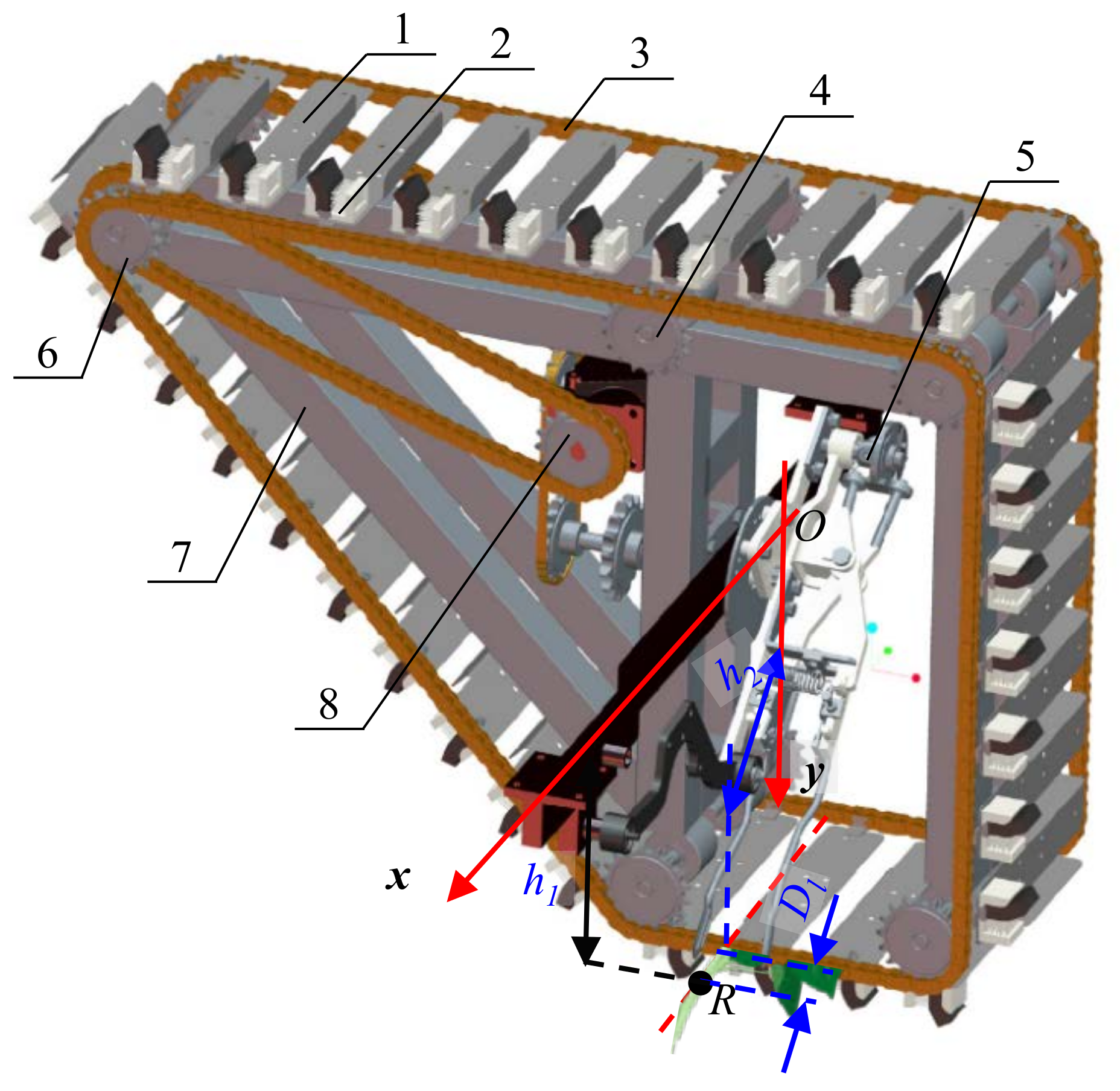
2.3.3. Slip Delivery Mechanism

As shown in Figure 10, the slip delivery mechanism was composed of a slip placement board, slip clamping brush, double-chain, transmission, etc. Orderly cooperation between the slip taking-planting mechanism and the slip delivery mechanism was essential for the continuous supply and transplanting of sweet potato slips. There were two key conditions to realize reliable and orderly cooperation: (1) the sweet potato slips, which were attached in the slip delivery mechanism, should pass through point R to be taken by the clip fingers; (2) when the slip taking-planting mechanism moved a circle, the slip delivery mechanism should simply supply one slip at point R. To realize the first condition, the following equation was formulated:
h 1 = y R h 2 = x R D l
where h1 is the vertical distance from the bottom of the slip clamping brush position to the center of the crank shaft (which is also the center of coordinate XOY), h2 is the horizontal distance from the end face of the slip clamping brush to the center of the crank shaft, and Dl is the nearest horizontal distance from the transplanting trajectory to the slip delivery mechanism.
Furthermore, to ensure that the clip fingers did not interfere with the slip delivery mechanism, Dl was designed as follows:
D l D z 2
Then, the length of the sweet potato slips that extended out of the tail of the brush was required in Formula (25) to guarantee the complete contact between the slips and the clip fingers.
D m D l + D z 2
where Dz is the width of the clip finger, mm; and Dm is the length of the sweet potato slip that extends out of the tail of the brush, mm. Then, the values of Dl, Dz, h1 and h2 were defined as 10 mm, 20 mm, 267 mm and 141 mm, respectively, based on the optimized values for the decision variables of the slip taking-planting mechanism. Furthermore, Dm was required to be more than 20 mm.
In addition, the kinematic relation between the slip taking-planting mechanism and the slip delivery mechanism was defined to satisfy the second condition, as follows:
n 1 n 2 = Z 2 Z 1
where n1 is the rotation speed of the slip taking-planting mechanism, r/min; n2 is the rotation speed of the slip delivery mechanism, r/min; Z1 is the chain number between each installed slip clamping brush; and Z2 is the number of sprocket teeth used by the slip delivery mechanism. In other words, each slip clamping brush should simply reach the point R to supply slips when the slip taking-planting mechanism moves a rotation.

2.4. Transmission Design of the Slip Transplanting Apparatus

According to the type and variety of sweet potato, such as fresh potatoes and industrial potatoes, the transplanting plant spacing differs from 18 cm to 30 cm. The following speed ratio relationships exist, as below, during the operation:
v = i × n1
dz = 60v/n1
where v is the forward speed of the machine, mm/s, and dz is the plant spacing. As shown in Figure 11a, the higher the transmission speed ratio i, the larger the transplanting plant spacing. When the transmission speed ratio i < 1.2 (corresponding plant spacing dz = 120 mm), the transplanting trajectories of each hole overlapped, which affected the transplanting quality. Thus, the slip transplanting apparatus met the requirement for transplanting plant spacing of 12 cm and above. Furthermore, the transmission speed ratio i between the ground wheel and the slip taking-planting mechanism was designed from 3 to 5, when the transplanting plant spacing differed from 18 cm to 30 cm. Therefore, the primary chain drive was adjustable. The complete transmission arrangement is shown in Figure 11b.

3. Materials and Methods for Field Experiment

3.1. Site Description and Plant Materials

Field trials were conducted over 2 years (2020 and 2021) at Sishui experiment station (35°30′ N, 117°15′ E) in the central south of Shandong, which is located in northern China. According to the USDA texture classification system, the soil at the station was silt loam, clay 12.3%, silt 74.8%, and sand 12.9%, on average. In the top 30 cm soil layer, soil bulk density, soil moisture and total porosity were 1.31 g/cm3, 12.8%, and ~40%, respectively.
The sweet potato cultivars Jishu 26 and Pushu 32, which were typical of those used in the sweet potato cultivation area of northern China, were selected for study. Sweet potato slips of the two cultivars were transplanted with the length of ~280 mm and diameter of 4~6 mm at the beginning of May by using the 2CGFS-2 compound sweet potato transplanter and harvested at the beginning of October in 2020 and 2021.
The experimental treatments were carried out in RBF and RB cultivation systems, respectively (Figure 12). For the RBF system, a high-density black polyethylene film (0.02 mm thick, 1.0 m wide) was used as the mulching plastic. The performance of the 2CGFS-2 compound transplanter with two different sweet potato cultivars in the RBF and RB cultivation systems was assessed using 12 split-plots in three complete, randomized blocks (i.e., 3 replications). Each plot was 2 m wide and 30 m long, with an access pathway and guard strip between each.
In this experiment, 375kg/ha [N-P2O5-K2O 10-8-24] compound fertilizer (containing total nutrients ≥ 42%, humic acid ≥ 3%, controlled-release K fertilize ≥ 4%) was applied as the basal fertilizer before the machine transplanting stage, and 33% pendimethalin EC herbicide (JiangSu Longdeng Chemical Company, Kunshan City, China) was sprayed onto the soil surface according to the manufacturer’s protocol during the transplanting.
The 2CGFS-2 compound transplanter, with a total mass of ca. 1150 kg, was 1.7 m wide with 2 transplanting rows at 85 cm spacing. A tractor with horsepower of no less than 90 hp should be equipped to achieve the multiple operations. The rotary tillage apparatus was powered through the gearbox driven by the tractor’s PTO shaft at 300~350 r/min, while the slip transplanting apparatus was driven by the ground wheel at a rotary speed of less than 60 r/min.
In this field trial, machine transplanting was carried out with a 180 hp tractor operating at a forward speed of 0.65 km/h and PTO rotary speed of 760 r/min. Then, sweet potato slips were planted at a plant spacing of 24 cm per row and plant density of more than 49,000 plants/ha, consistent with the soil fertility. Timely surface drip irrigation was applied after transplanting to ensure the survival of the sweet potato slips. Weeds were removed several times from the field in the RB cultivation system in the early planting stage. No additional management practices (e.g., irrigation, pest management) were applied during the entire growing season in either field.

3.2. Missing Seedling Rate and Qualified Rate of Transplanting Population

The missed sweet potato slip population, replanted slip population, exposed slip population, injured slip population and total slip population were counted by examining more than 120 continuously planted sweet potato slips at the 12 split-plots in three complete, randomized blocks. Then, the missing seedling rate and qualified rate of transplanting population, which represents the transplanting quality, were calculated according to the machinery industry standard of China JB/T 10291-2013 “Transplanter of dry land plant” [32] and agricultural industry standard of China NY/T 3486-2019 “Operating quality for vegetable transplanter” [33]:
Q M = N L Z N × 100 %
Q z = N T N L M + N C Z + N S M N × 100 %
where QM is the missing seedling rate, %; QZ is the qualified rate of transplanting population, %; NT is the total count of the sweet potato slips planted in the plots; N’ is the theoretical plant count in the plots; NLZ is the missed sweet potato slip population; NLM is the exposed slip population; NCZ is the replanted slip population; and NSM is the injured slip population.

3.3. Uniformity of Transplant Spacing and Qualified Rate of Transplanting Depth

In each replication, the plant spacing and planting depth of more than 60 and 30 planted sweet potato slips, respectively, were measured for the randomly selected planting row. Uniformity of transplant spacing and qualified rate of transplanting depth were calculated to assess the transplanting accuracy [32,33]:
C V X = 1 n 1 i = 1 n ( X i i = 1 n X i n ) 2 i = 1 n X i n × 100 %
C V H = N h N T × 100 %
where CVX is the plant spacing coefficient of variation to assess the uniformity of transplanting spacing; n is the measured number of planted slips; Xi is the measured plant spacing, cm; CVH is the qualified rate of transplanting depth; and Nh is the sweet potato count of qualified depth. As the designed transplanting depth was 60 mm, we assumed the qualified depth was 60 ± 10 mm.

3.4. Length of Sweet Potato Slips under the Soil

Length of sweet potato slips under the soil was related to the potential number of growing sweet potato root tubers, which was positively correlated with the sweet potato yield of each plant. In each plot, after measuring the planting depth of the above selected sweet potato slips, each slip was pulled out, and the length measurement was taken from its intersection with the soil surface to its endpoint.

3.5. Tuber Yield

At the harvest time (beginning of October) in 2020 and 2021, all of the branches of the sweet potato were removed. Additionally, the tubers were collected manually from 30 randomly selected plants in each plot. Samples were brought to the laboratory, washed in fresh water, and dried in an oven to determine the mean fresh tuber weight per plant. Then, the tuber yield was determined based on the mean weight of fresh tubers per plant. In each replication of the treatments, the rate of variation in tuber weight per sample plant was calculated by comparing the lowest tuber weight per plant with the highest tuber weight per plant.

3.6. Data Analysis

Mean values were calculated for each of the measurements, and ANOVA was used to assess the effects of the 2CGFS-2 compound sweet potato transplanter on the different treatments (two sweet potato cultivars and two cultivation systems). When ANOVA indicated a significant F-value, multiple comparisons of annual mean values were performed by the least significant difference (LSD) method. In all analyses, a probability of error smaller than 5% (p = 0.05) was considered statistically significant.

4. Results and Discussion

4.1. Missing Seedling Rate and Qualified Rate of Transplanting Population

The missing seedling rate QM and qualified rate of transplanting population QZ for each treatment were <1.2% and >95.0%, respectively, in both 2020 and 2021 (Table 1), which were all better than the values specified in the standard [32]. Mean values of QM and QZ for Pushu 32 in the RBF and RB systems were the same, i.e., 0.84% and 96.67%, respectively, during 2020–2021. For Jishu 26, the means of QM and QZ were, respectively, 0.42% and 97.77% in the RBF system, while they were 0.83% and 97.10% in the RB system. A significantly (p < 0.05) smaller missing seedling rate and greater qualified rate of transplanting population were founded in the Jishu 26 + RBF treatment, compared with the Pushu 32+RBF treatment. As shown in Table 1, there was a positive correlation between the missing seedling rate and qualified rate of transplanting population. The transplanting quality (QM and QZ) of the 2CGFS-2 compound transplanter in the RBF system was consistent with the research of Murakami et al. [24]. Additionally, the differences in the transplanting quality for the RBF and RB cultivation systems were not significant.

4.2. Uniformity of Transplant Spacing and Qualified Rate of Transplanting Depth

The plant spacing coefficient of variation for all treatments varied from 2.64% to 5.58% in 2020 and from 3.14% to 6.82% in 2021, but the differences were not significant (p > 0.05) (Table 2). The mean value of the plant spacing coefficient of variation for the 2CGFS-2 compound sweet potato transplanter during 2020–2021 was 4.53%, a decrease of 3.9% compared with the value of the horizontal transplanter for sweet potato seedlings designed by Yan et al. [34]. The reason may be that the slip transplanting apparatus of the 2CGFS-2 compound sweet potato transplanter was designed to be driven by the ground wheel.
As shown in Table 2, the type of sweet potato cultivar and cultivation system had no significant effect on the qualified rate of transplanting depth during 2020–2021. Mean qualified rate of transplanting depth for four treatments was 96.28%. The treatment Pushu 32 + RBF had significant 5.23% and 3.35% (p < 0.05) lower qualified rates of transplanting depth compared with the qualified rates of treatment Jishu 26 + RBF and Jishu 26 + RB, respectively, in 2021. All of the mean values of the qualified rate of transplanting depth were much higher than 75%, indicating that the transplanting accuracy of the 2CGFS-2 compound sweet potato transplanter satisfied the corresponding specifications recorded in the standards [32,33].

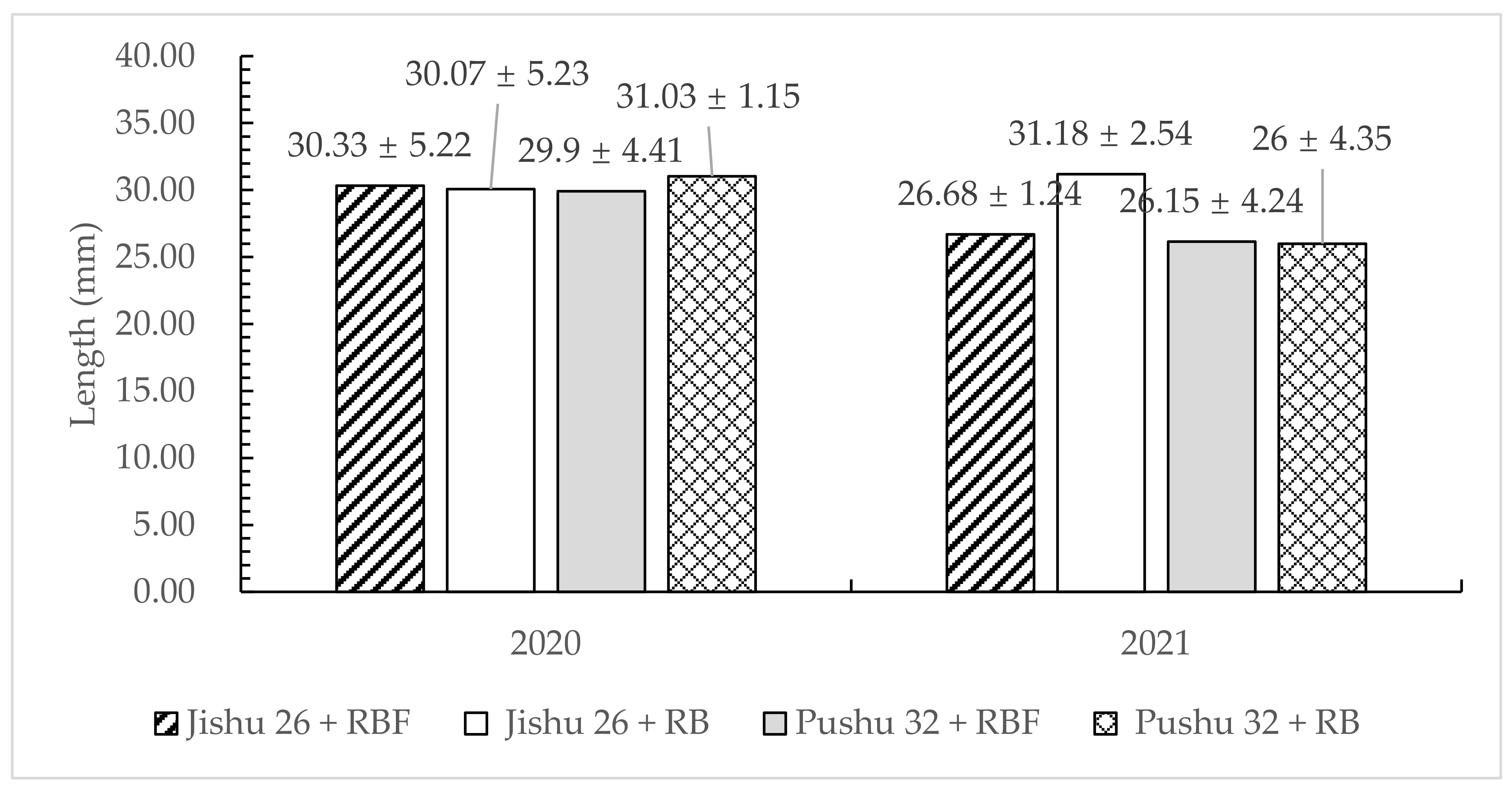
4.3. Length of Sweet Potato Slips under the Soil

The length of sweet potato slips under the soil after transplanting by the 2CGFS-2 compound sweet potato transplanter under the four treatments was similar in 2020 and 2021 (Figure 13). In addition, the mean values of the length under the soil were 193.7 mm, 195.0 mm, 194.5 mm and 193.3 mm for the Jishu 26 + RBF, Jishu 26 + RB, Pushu 32 + RBF, and Pushu 32 + RB treatments, respectively. The difference in length of sweet potato slips under the soil in the four treatments was negligible (p > 0.05). Furthermore, mean length of sweet potato slips under the soil was 0.45% lower than the designed value. The insignificant deviation might be caused by the insufficiently accurate placement of the sweet potato slips in the slip delivery mechanism or by the differences in erect characteristics of individual sweet potato slips. Since the differences in the length of sweet potato slips under the soil between the four treatments from 2020 to 2021 were much smaller than the internode length of each sweet potato variety (ca. 40 mm), the accurate placement by the 2CGFS-2 compound sweet potato transplanter could reduce the differences in tuber weight per plant caused by manual transplanting.

4.4. Tuber Yield

The mean tuber yields for the Jishu 26+RBF, Jishu 26+RB, Pushu 32+RBF, and Pushu 32+RB treatments were 48.02, 38.42, 45.69, and 36.91 t/ha, respectively, for the 2020 transplanting year. The results were similar in 2021, with slight declines in all four treatments (Table 3), which might be due to the increased rainfall that year. The fresh tuber yield of the Jishu 26+RB treatment was consistent with the results of Quan et al. [35]. No significant differences were found between the Jishu 26 and Pushu 32 sweet potato cultivars, which are both fresh sweet potato varieties with high yields [7].
Among the RBF treatments, mean fresh tuber yields for Jishu 26 and Pushu 32 were 27.1% and 22.5%, respectively, significantly (p < 0.05) higher than those in RB treatments. The data indicated more tuber growth of the sweet potatoes under the RBF treatments, since RBF was proven to be effective in improving soil water moisture and soil temperature [11,12,13]. Similar results was also shown in the researches by Hou et al. [13] and Li et al. [36]. Chagonda et al. also concluded that soil moisture and temperature influence the sub-aerial soil microclimate around the sweet potato plant, which has an effect on storage root initiation, growth and development [26].
In each treatment, the tuber weight per plant was inconsistent and varied by up to 35% (Figure 14). Firon et al. [37] also highlighted that production of storage roots was inconsistent from plant to plant of the same cultivar under similar field conditions. The tuber weight per plant in this research had better consistency compared with the experiments of Villordon et al. [38], in which the tuber weight per plant varied by up to 50%. The results indicated that the 2CGFS-2 compound sweet potato transplanter decreased the tuber weight differences per plant by contributing to more consistent planting quality of each plant.

5. Conclusions

This study developed a 2CGFS-2 compound sweet potato transplanter to satisfy the requirements for shallow planting and multi-buried nodes in the RBF and RB cultivation systems. Comparative field trials of the 2CGFS-2 compound sweet potato transplanter in RBF and RB cultivation systems with Jishu 26 and Pushu 32 sweet potato cultivars in northern China demonstrated that:
(1)
The missing seedling rate QM and qualified rate of transplanting population QZ for each treatment using the 2CGFS-2 compound transplanter were <1.2% and >95.0% in both 2020 and 2021, which were all better than the values specified in the standard.
(2)
The plant spacing coefficient of variation for all treatments varied from 2.64% to 5.58% in 2020 and from 3.14% to 6.82% in 2021. However, the differences were not significant (p > 0.05). The type of sweet potato cultivar and cultivation system had no significant effect on the qualified rate of transplanting depth during 2020–2021, which, with a mean value of 96.28%, was much higher than the 75% recorded in the standards.
(3)
The mean values of the length under the soil were 193.7 mm, 195.0 mm, 194.5mm and 193.3 mm for the Jishu 26+RBF treatment, Jishu 26 + RB treatment, Pushu 32 + RBF treatment, and Pushu 32+RB, respectively, using the 2CGFS-2 compound sweet potato transplanter. The differences were negligible (p > 0.05), and the deviation in the length was much smaller than the internode length of each sweet potato variety (ca. 40 mm).
(4)
Among the RBF treatments, mean fresh tuber yields for Jishu 26 and Pushu 32 were 27.1% and 22.5%, respectively, significantly (p < 0.05) higher than those in the RB treatments. In each treatment, the tuber weight per plant was inconsistent and varied by up to 35%, but the inconsistency was alleviated by the improved planting quality of each sweet potato plant using the 2CGFS-2 compound transplanter.
The designed 2CGFS-2 compound sweet potato transplanter might provide a useful and highly efficient transplanting implement for not only northern China, but also any other location with the same conditions. Furthermore, it has the advantage of improving transplanting quality and accuracy for different cultivars in RBF and RB cultivation systems. However, long-term experiments are needed to evaluate the soil compaction after the use of mechanized transplanting. In addition, we will also conduct in-depth research to assess the suitability of the 2CGFS-2 compound sweet potato transplanter for various sweet potato cultivars and soil types. The data obtained in this research are helpful in developing sweet potato transplanting equipment applicable in various cultivation systems.

Author Contributions

Conceptualization, H.L. (Hui Li) and S.S.; methodology, T.H.; machine design, J.Z. and H.L. (Hu Liu); parameter optimization, H.L. (Hui Li); field experiment, B.W. and X.L.; validation, J.Z., G.W. and H.L. (Hu Liu).; data curation, R.Z.; writing—original draft preparation, H.L. (Hui Li); writing—review and editing, J.Z.; supervision, B.W.; project administration, H.L. (Hui Li); funding acquisition, B.W. All authors have read and agreed to the published version of the manuscript.

Funding

This research was funded by National Key R&D Program of China (Grant No. 2020YFD1000800), Agricultural science and technology innovation project of Shandong Academy of Agricultural Sciences (Grant No. CXGC2022A31), Opening Foundation of Huang Huai Hai Key laboratory of Modern Agricultural Equipment by Ministry of Agriculture and Rural Affairs of China (Grant No. NJY2022QN05) and Shandong Tobacco industry technology system.

Institutional Review Board Statement

Not applicable.

Informed Consent Statement

Not applicable.

Data Availability Statement

Not applicable.

Acknowledgments

Our thanks to Shandong Huorong Agricultural Technology Development Co. for its manufacturing services and to Sishui Panghaibo Planting Professional Co-op.

Conflicts of Interest

The authors declare no conflict of interest.

References

  1. Oladejo, A.O.; Ma, H.; Qu, W.; Zhou, C.; Wu, B.; Yang, X. Influence of ultrasound pretreatments on diffusion coefficients, texture and colour of osmodehydrated sweet potato (Ipomea batatas). Int. J. Food Sci. Technol. 2017, 52, 888–896. [Google Scholar] [CrossRef]
  2. Low, J.; Ball, A.; Magezi, S.; Njoku, J.; Mwanga, R.; Andrade, M.; Tomlins, K.; Dove, R.; Mourik, T.V. Sweet potato development and delivery in sub-Saharan Africa. Afr. J. Food Agric. Nutr. Dev. 2017, 17, 11955–11972. [Google Scholar] [CrossRef]
  3. Huang, Z.; Liu, Y.; Qi, G.; Brand, D.; Zheng, S. Role of Vitamin A in the Immune System. J. Clin. Med. 2018, 7, 258. [Google Scholar] [CrossRef] [PubMed]
  4. FAO (Food and Agriculture Organization). FAOSTAT Online Statistical Database: Crops and Livestock Products 2020. Available online: http://www.fao.org/faostat/zh/#data/QC (accessed on 17 February 2022).
  5. FAO (Food and Agriculture Organization). FAOSTAT Online Statistical Database: Food Balance 2019. FAOSTAT. Available online: http://www.fao.org/faostat/zh/#data/QC (accessed on 17 February 2022).
  6. Agili, S.; Nyende, B.; Ngamau, K.; Masinde, P. Selection, yield, drought tolerance indices of orange-fleshed sweet potato (Ipomoea batatas Lam) hybrid clone. J. Nutr Food Sci. 2012, 2, 1–8. [Google Scholar]
  7. Wang, B. Overview of sweet potato production in China. In Main Cultivation Modes of Sweet Potato in China, 1st ed.; Zhang, L., Ma, D., Wang, Q., Wang, B., Eds.; China Agricultural Science and Technology Press: Beijing, China, 2012; pp. 1–8. [Google Scholar]
  8. Sun, H.Y.; Zhang, X.Y.; Chen, S.Y.; Pei, D.; Liu, C.M. Effects of harvest and sowing time on the performance of the rotation of winter wheat-summer maize in the North China Plain. Soil Tillage Res. 2007, 25, 239–247. [Google Scholar] [CrossRef]
  9. NBSC (National Bureau of Statistics, China). The Statistical Bulletin of National Economy and Social Development in China; Peoples Republic of China, National Bureau of Statistics: Beijing, China, 2012. [Google Scholar]
  10. Belehu, T. Agronomical and Physiological Factors Affecting Growth, Development and Yield of Sweet Potato in Ethiopia; Doctor of Philosophy, University of Pretoria: Hatfield, Pretoria, 2003. [Google Scholar]
  11. Kuranouchi, T.; Nakamura, Y.; Takada, A.; Tamiya, S.; Nakatani, M.; Kumagai, T. Effects of mulching with polyethylene film and weather on agronomic characters of sweet potato varieties for steamed and cured slices processing. Jpn. J. Crop Sci. 2010, 79, 491–498. [Google Scholar] [CrossRef]
  12. Gajanayake, B.; Reddy, K.R.; Shankle, M.W.; Arancibia, R.A. Growth, developmental, and physiological responses of two sweetpotato [Ipomoea batatas L. (Lam)] cultivars to early season soil moisture deficit. Sci. Hortic. 2014, 168, 218–228. [Google Scholar] [CrossRef]
  13. Hou, F.; Zhang, L.; Xie, B.; Dong, S.; Zhang, H.; Li, A.; Wang, Q. Effect of plastic mulching on the photosynthetic capacity, endogenous hormones and root yield of summer-sown sweetpotato (Ipomoea batatas (L). Lam.) in Northern China. Acta Physiol. Plant. 2015, 37, 164. [Google Scholar] [CrossRef]
  14. Jiang, Y.; Shi, C.; Wang, Z.; Wang, C.; Liu, H. Effects of plastic film mulching on arable layer soil temperature, moisture and yield of sweet potato. Chin. J. Eco-Agric. 2014, 22, 627–634. [Google Scholar]
  15. Hou, F.Y.; Dong, S.X.; Xie, B.T.; Zhang, H.Y.; Li, A.X.; Wang, Q.M. Mulching with plastic film improved the root quality of summer-sown sweet potato (Ipomoea batatas (L). Lam.) in northern China. J. Integr. Agric. 2019, 18, 982–991. [Google Scholar] [CrossRef]
  16. Prasanna Kumar, G.V.; Raheman, H. Vegetable Transplanters for Use in Developing Countries—A Review. Int. J. Veg. Sci. 2008, 14, 232–255. [Google Scholar] [CrossRef]
  17. Checchi & Magli Transplanters. Available online: https://www.checchiemagli.com/macchine/trapiantatrice-foxdrive-r14/ (accessed on 7 October 2018).
  18. Mulch Equipment-Holland Transplanter. Available online: https://transplanter.com/mulch-equipment/ (accessed on 29 September 2016).
  19. FPC Layer and Transplanter. Available online: https://ferraricostruzioni.com/en/film-transplanters/23-fpc-layer-and-transplanter.html (accessed on 19 May 2022).
  20. Liu, J.; Cao, W.; Tian, D.; Zhao, H. Kinematic Analysis and Test on Transplanting Mechanism with Effective Zero-speed Transplanting on Mulch Film. J. Mech. Eng. 2017, 53, 76–84. [Google Scholar] [CrossRef]
  21. Hu, L.; Hu, Z.; Xie, Y.; Tian, L.; Ji, F.; Wang, B. Study on the route of mechanization of sweet potato (ipomoea batatas lam.) production technology in China. Chin. Agric. Mech. 2011, 5, 20–25. [Google Scholar]
  22. Chen, L.H.; Younis, T.S.; Allison, M. Horizontal Transplanting of Sweet Potatoes. Trans. ASAE 1982, 25, 1524–1528. [Google Scholar] [CrossRef]
  23. Hu, L.; Wang, B.; Wang, G.; Yu, Z.; You, Z.; Hu, Z.; Wang, B.; Gao, X. Design and experiment of type 2ZGF-2 duplex sweet potato transplanter. Trans. Chin. Soc. Agric. Eng. 2016, 32, 8–16. [Google Scholar]
  24. Murakami, K.; Takahiko, T.; Yamaguchi, H.; Tanazaki, A. Seedling Transplanter. CN Patent 103988621B, 20 August 2014. [Google Scholar]
  25. Parwada, C.; Gadzirai, C.T.; Sithole, A.B. Effect of Ridge Height and Planting Orientation on Ipomoea Batatas (sweet potato) Production. J. Agric. Biotechnol. Sustain. Dev. 2011, 3, 72–76. [Google Scholar]
  26. Chagonda, I.; Mapfeka, R.F.; Chitata, T. Effect of Tillage Systems and Vine Orientation on Yield of Sweet Potato (Ipomoea batatas L.). Am. J. Plant. Sci. 2014, 5, 3159–3165. [Google Scholar] [CrossRef]
  27. Ma, D.; E, W. Handbook of Green Light Simplified Cultivation Techniques for Sweet Potato, 1st ed.; China Agricultural Press: Beijing, China, 2021. [Google Scholar]
  28. Wang, B.Q.; Zhang, L.M. Research progress on growth and development of sweet potato roots affected by environmental factors and agronomic measure. J. Jiangsu Norm. Univ. (Nat. Sci. Ed.) 2017, 35, 11–22. [Google Scholar]
  29. Li, Y. Mechanism analysis and synthesis. In Mechanical Principle, 1st ed.; Wei, W., Gao, Y., Zhang, Y., Eds.; China Agricultural University Press: Beijing, China, 2005; pp. 22–38. [Google Scholar]
  30. Hrones, J.A.; Nelson, G.L. Analysis of the Four-Bar Linkage: Its Application to the Synthesis of Mechanisms, 1st ed.; The Technology Press of the MIT and John Wiley&Sons, INC.: New York, NY, USA, 1951. [Google Scholar]
  31. Su, Z.J.; Wang, G.H.; Yan, J.H.; Dong, C.J. Evaluation Model of Rural Drinking Water Project Based on Entropy Weight and Fuzzy Comprehensive Evaluation Method. Asian Agric. Res. 2022, 14, 62–65. [Google Scholar]
  32. Ministry of Industry and Information Technology of the People’s Republic of China. JB/T 10291-2013 Transplanter of Dry Land Plant; Machinery Industry Press: Beijing, China, 2013. [Google Scholar]
  33. Ministry of Agriculture and Rural Affairs of the People’s Republic of China. NY/T 3486-2019 Operating Quality for Vegetable Transplanter; China Agricultural Press: Beijing, China, 2019. [Google Scholar]
  34. Yan, W.; Hu, M.; Li, K.; Wang, J.; Zhang, W. Design and Experiment of Horizontal Transplanter for Sweet Potato Seedlings. Agriculture 2022, 12, 675. [Google Scholar] [CrossRef]
  35. Quan, B.; Ren, J.; Zhao, J.; Guo, P.; Xu, Y. Effects of Different Cutting Density and Cutting Time on Yield and Commercial Tuber Rate of Jishu 26. J. Shanxi Agric. Sci. 2021, 49, 869–871. [Google Scholar]
  36. Li, J.H.; Jia, Z.R.; Wang, L.Y.; Xie, X.H.; Xie, H.E.; Wu, Z.X.; Li, B. Effect of Ridge Tillage with Plastic Film Mulching on Temperature Increase and Preservation of Soil Moisture and Yield of Sweet Potato. J. Shanxi Agric. Sci. 2016, 44, 494–497. [Google Scholar]
  37. Firon, N.; LaBronte, D.; Villordon, A.; McGregor, C.; Kfir, Y.; Pressman, E. Botany and Physiology: Storage Root Formation and Development. In The Sweet Potato; Loebenstein, G., Thottapilly, G., Eds.; Springer Science + Bussiness Media BV: Berlin/Heidelberg, Germany, 2009; pp. 13–26. [Google Scholar]
  38. Villordon, D.R.; La Bonte, D.R.; Firon, N.; Kfir, K.; Pressman, E.; Schwartz, A. Characterization of Adventitious Root Development in Sweet Potato. HortScience 2009, 44, 651–655. [Google Scholar] [CrossRef]
Figure 1. Sweet potato slips are planted manually in the raised beds (RB) and raised beds mulched with plastic film (RBF) cultivation systems in northern China. (a) RB cultivation system; (b) RBF cultivation system.
Agriculture 12 01184 g001
Figure 2. Model of planting sweet potato slips by boat-shaped placement. (a) Placement of sweet potato slips at planting; (b) Model of planting sweet potato slips by boat-shaped placement.
Agriculture 12 01184 g002
Figure 3. Structure of the 2CGFS-2 compound transplanter for sweet potato slip cultivation in the RBF and RB cultivation systems in northern China. Note: 1, Transmission box; 2, Lateral sealing plate; 3, Rotary component; 4, Ridging board; 5, Ridging opener; 6, Film pressing wheel; 7, Soil covering disc; 8, Driving wheel; 9, Height adjustment; 10, slip taking-planting mechanism; 11, Chair; 12, Frame; 13, Drive system; 14, Slip delivery mechanism; 15, Plastic-film frame; 16, Laying device of drip irrigation belt; 17, Three-point hitch system.
Agriculture 12 01184 g003
Figure 4. The structure and parameter design of the slip taking-planting mechanism. (a) Mechanical structure of the mechanism. (b) Schematic model of the mechanism. Note: 1, Frame; 2, Rocker; 3, Connecting rod; 4, Crank; 5, Seedling clamping assembly; 5-1, Driving cam; 5-2, Roller; 5-3, Bracket; 5-4, Guide rail; 5-5, Spring; 5-6, Clip finger I; 5-7, Clip finger II; 6, Sweet potato slips. A, B, C, D, E, hinge points of each bar; l1, length of the crank; l2, length of the connecting rod; l3, length of the rocker; l4, length of the frame; l5, length of the working rod; xA, horizontal ordinate of the hinge point A; yA, longitudinal coordinate of the hinge point A; θ, angle between the working rod and the connecting rod; φ0, angle of the rack; φ, rotating angle of the crank.
Agriculture 12 01184 g004
Figure 5. Influence of parameters on the trajectory E(x, y). (a) Relationship between l2 and the trajectory; (b) relationship between l3 and the trajectory; (c) relationship between l4 and the trajectory; (d) relationship between l5 and the trajectory; (e) relationship between θ and the trajectory; (f) relationship between φ0 and the trajectory.
Agriculture 12 01184 g005aAgriculture 12 01184 g005b
Figure 6. Transplanting track and main parameter points. Note: P, the uppermost point of the planting track; M, the deepest point of the planting track; N, the farthest point of the planting track; R, the nearest point of the planting track; H, the penetrating point; Q, the unearthed point.
Agriculture 12 01184 g006
Figure 7. Optimal solution method for decision variables.
Agriculture 12 01184 g007
Figure 8. The organization of the working sequence between the crank rocker assembly and seedling clamping assembly. (a) Relationship between ∠ABC and the independent variable φ. (b) Initial work status. Note: A, B, C, D, hinge points of each bar consistent with the symbols in Figure 4; P, the uppermost point of the planting track; M, the deepest point of the planting track; N, the farthest point of the planting track; R, the nearest point of the planting track; H, the penetrating point; Q, the unearthed point; S0, the initial position; φS0, the angle value of the independent variable φ at the initial position.
Agriculture 12 01184 g008
Figure 9. The kinematics simulation analysis of the slip taking-planting mechanism. (a) Simulation model. (b) Trajectory of the clip finger in the slip taking-planting mechanism. Note: P, the uppermost point of the planting track; M, the deepest point of the planting track; N, the farthest point of the planting track; R, the nearest point of the planting track; H, the penetrating point; Q, the unearthed point; S0, the initial position; d, the distance between the trajectories of clip finger I and II.
Agriculture 12 01184 g009
Figure 10. Slip delivery mechanism for slip transplanting. Note: 1, Slip placement board; 2, Slip clamping brush; 3, Double-chain; 4, Sprocket; 5, Slip taking-planting mechanism; 6, Sprocket carrier; 7, Frame; 8, Transmission.
Agriculture 12 01184 g010
Figure 11. Transmission design of the slip transplanting apparatus. (a) The planting trajectory of the slip transplanting apparatus during operation. (b) Transmission path. Note: 1, Cardon joint; 2, Gearbox; 3, Rotary blade group; 4, Commutator; 5, Slip delivery mechanism; 6, Slip taking-planting mechanism; 7, Ground wheel; 8, Frame; 9, Middle line of the ridge; 10, Sprocket; 11, Chain drive; 12, Adjustable primary chain drive.
Agriculture 12 01184 g011
Figure 12. 2CGFS-2 compound sweet potato transplanter working in RBF and RB cultivation systems. (a) The designed transplanter working in RBF cultivation system and (b) RB cultivation system.
Agriculture 12 01184 g012
Figure 13. Length of sweet potato slips under the soil after transplanting by the 2CGFS-2 compound sweet potato transplanter under the four treatments in 2020 and 2021. Note: Values with the same letters within each cropping year were not significantly different at p = 0.05.
Agriculture 12 01184 g013
Figure 14. Rate of variation in tuber weight per plant after transplanting by the 2CGFS-2 compound sweet potato transplanter under the four treatments in 2020 and 2021.
Agriculture 12 01184 g014
Table 1. Transplanting quality of the 2CGFS-2 compound sweet potato transplanter for two sweet potato cultivars under RBF and RB cultivation systems in 2020 and 2021. Note: Means of the same year within a column followed by the same letters are not significantly different at p = 0.05.
Transplanting YearTreatmentsMissing Seedling Rate QM/%Qualified Rate of Transplanting Population QZ/%
2020Jishu 26 + RBF0.67 a96.77 a
Jishu 26 + RB0.83 a96.33 a
Pushu 32 + RBF0.67 a95.80 a
Pushu 32 + RB1.17 a95.23 a
2021Jishu 26 + RBF0.17 a98.77 a
Jishu 26 + RB0.83 ab97.87 ab
Pushu 32 + RBF1.00 b97.53 b
Pushu 32 + RB0.50 ab98.10 ab
Table 2. Transplanting accuracy of the 2CGFS-2 compound sweet potato transplanter for two sweet potato cultivars under the RBF and RB cultivation systems in 2020 and 2021. Note: Means of the same year within a column followed by the same letters are not significantly different at p = 0.05.
Transplanting YearTreatmentsPlant Spacing Coefficient of Variation CVX/%Qualified Rate of Transplanting Depth CVH/%
2020Jishu 26 + RBF 3.83 a95.17 a
Jishu 26 + RB 4.61 a97.41 a
Pushu 32 + RBF 3.75 a96.52 a
Pushu 32 + RB 4.43 a94.82 a
2021Jishu 26 + RBF 4.99 a98.96 a
Jishu 26 + RB5.82 a97.15 a
Pushu 32 + RBF5.71 a94.00 b
Pushu 32 + RB3.14 a96.23 ab
Table 3. Tuber yield with the 2CGFS-2 compound sweet potato transplanter for four treatments in 2020 and 2021. Note: Means of the same year within a column followed by the same letters are not significantly different at p = 0.05.
Transplanting YearTreatmentsTubers Weight Per Plant/kgTuber Yield Per Hectare/t
2020Jishu 26 + RBF0.98 a48.02 a
Jishu 26 + RB0.78 b38.42 b
Pushu 32 + RBF0.93 a45.69 a
Pushu 32 + RB0.75 b36.91 b
2021Jishu 26 + RBF0.94 a46.06 a
Jishu 26 + RB0.73 b35.61 b
Pushu 32 + RBF0.90 a44.22 a
Pushu 32 + RB0.74 b36.46 b
Publisher’s Note: MDPI stays neutral with regard to jurisdictional claims in published maps and institutional affiliations.

