Article

Design and Test of Longitudinal Axial Flow Staggered Millet Flexible Threshing Device

College of Agricultural Equipment Engineering, Henan University of Science and Technology, Luoyang 471000, China
*
Author to whom correspondence should be addressed.
Agriculture 2022, 12(8), 1179; https://doi.org/10.3390/agriculture12081179
Submission received: 12 July 2022 / Revised: 3 August 2022 / Accepted: 5 August 2022 / Published: 8 August 2022
(This article belongs to the Special Issue Advances in Agricultural Engineering Technologies and Application)

Abstract

:
In order to solve the problems of high millet agglomerates rate, high damage rate, and high undelivered net loss rate in the process of mechanized harvesting of millet, a longitudinal axial flow-staggered flexible threshing device for millet was designed on the basis of the existing threshing device. The “staggered teeth” threshing drum and the micro rotating circular tube concave screen work together to realize the flexible and low damage threshing of millet. The pre experiment was carried out first, and the factors that have a great impact on the millet agglomerates rate, the undelivered net loss rate, and the damage rate were found to be the feeding amount, the rotating speed of the drum, and the threshing clearance. In order to further explore the influence of the interaction between the factors on the millet agglomerates rate, the undelivered net loss rate, and the damage rate, the regression orthogonal rotation combination test was carried out, and after the test, the optimal parameter combination of feeding amount, drum speed, and threshing clearance was determined. The results showed that when the feeding amount was 1.3 kg/s, the rotating speed of the drum was 762 r/min−1 and the concave clearance was 15 mm, the millet agglomerates rate was 2.92%, the high undelivered net loss rate was 1.58%, and the damage rate was 0.37%.

1. Introduction

Millet is an important cereal crop in China, and its production and consumption scale ranks first in the world. According to the statistics of the national millet and sorghum industrial technology system, in 2020, China’s millet planting area was about 1.5 million hm2, with a total output of about 10 million tons. Moreover, millet is also an important cash crop in China. The output of millet in China accounts for about 80% of the world’s output. The raw grain of millet is mainly exported to Japan, South Korea, and other countries [1,2,3,4,5]. The mechanized harvest of millet is an important link to realize the mechanization of the whole process of millet production. It can reduce grain loss, reduce labor intensity, and improve production efficiency.
The threshing device is the core component of grain harvesters, which determines the quality of grain harvest. Longitudinal axial flow threshing devices have the advantages of long threshing time, soft threshing, low damage rate, and high threshing efficiency [6,7,8,9]. The threshing elements of traditional grain combine harvesters are rigid. The grain code can easily fall off during threshing, so the millet agglomerates rate and damage rate are both high. Therefore, it is urgent to design a new type of millet threshing device with low millet agglomerates rate, low damage rate, and low undelivered net loss rate.
Millet cultivation in foreign developed countries is lower, and it is mostly used as feed [10,11,12], so the research that can be used as a reference is limited. Arnold [13] divided the traditional threshing into impact threshing, rubbing threshing, and combing threshing through many experiments, and pointed out that impact threshing is the main threshing form causing grain damage. According to this conclusion, the threshing device designed in this study will reduce the impact on millet. Powar [14] found that the main cause of millet grain damage is mechanical impact, but did not put forward an effective method to solve this problem. Gummert [15] conducted the threshing performance test of the axial-flow threshing device and found that appropriately increasing the rotating speed of the threshing drum within a certain range can significantly improve the threshing efficiency of threshing device, but there is a lack of research on the impact of increasing the rotating speed of threshing drum on various indexes of threshing quality.
The research and development of domestic millet combine harvesters is still in its infancy. With the national attention to the realization of mechanized grain harvest, the research of scientific researchers has also made some progress. Xu [16] theoretically analyzed the axial threshing and separation system and established a mathematical model to provide a design basis for the structural design of the longitudinal axial flow drum. Wu [17] conducted a flexible beating test on Millet ears, which proved that the flexible threshing method can be applied to millet threshing. First, the suitable parameters of grain separation in high-speed photography were established, and then the appropriate parameters of grain separation in high-speed photography were established. Zhang [18] developed an axial-flow threshing and separation test-bed for millet with rod teeth, but the rod teeth had a great impact on the ear of millet, which could easily increase the grain damage rate and millet agglomerates rate, and the overall threshing effect was poor. Zong [19] found that the combination effect of impact and rubbing was better by comparing the effects of three different threshing methods on the threshing effect of rape, which proved the feasibility of integrating multiple threshing methods for optimizing the threshing effect.
At present, there is little research on flexible threshing elements at home and abroad. Most of the threshing elements of the threshing drum on the combine harvester are mainly rigid elements such as corrugated rods and rod teeth [20,21,22,23,24,25], but this is not suitable for threshing millet. The traditional threshing device such as bar threshing devices can not meet the requirements of millet threshing because of its high millet agglomerates rate, high damage rate, and high undelivered net loss rate. The purpose of this study was to reduce the millet agglomerates rate to less than 3.5%, the undelivered net loss rate to less than 3%, and the damage rate to less than 0.5%. In order to achieve this goal, the plan of this study was to design the threshing device according to the existing foundation. Then the mathematical model was established by using Hertz collision theory and D’Alembert principle to carry out kinematic analysis. Finally, according to the experimental data, we analyzed the influencing factors and established a mathematical model for parameter optimization. The type of threshing element in this design was a “staggered type”, which has a better fit with the ear of millet and is conducive to millet threshing. The material of the threshing element is rubber, which has a flexible impact on millet. The combination of the “staggered teeth” threshing element and the micro rotating circular tube concave screen can effectively solve the problems of high millet agglomerates rate, high damage rate, and high undelivered net loss rate in the threshing process of millet.

2. Materials and Methods

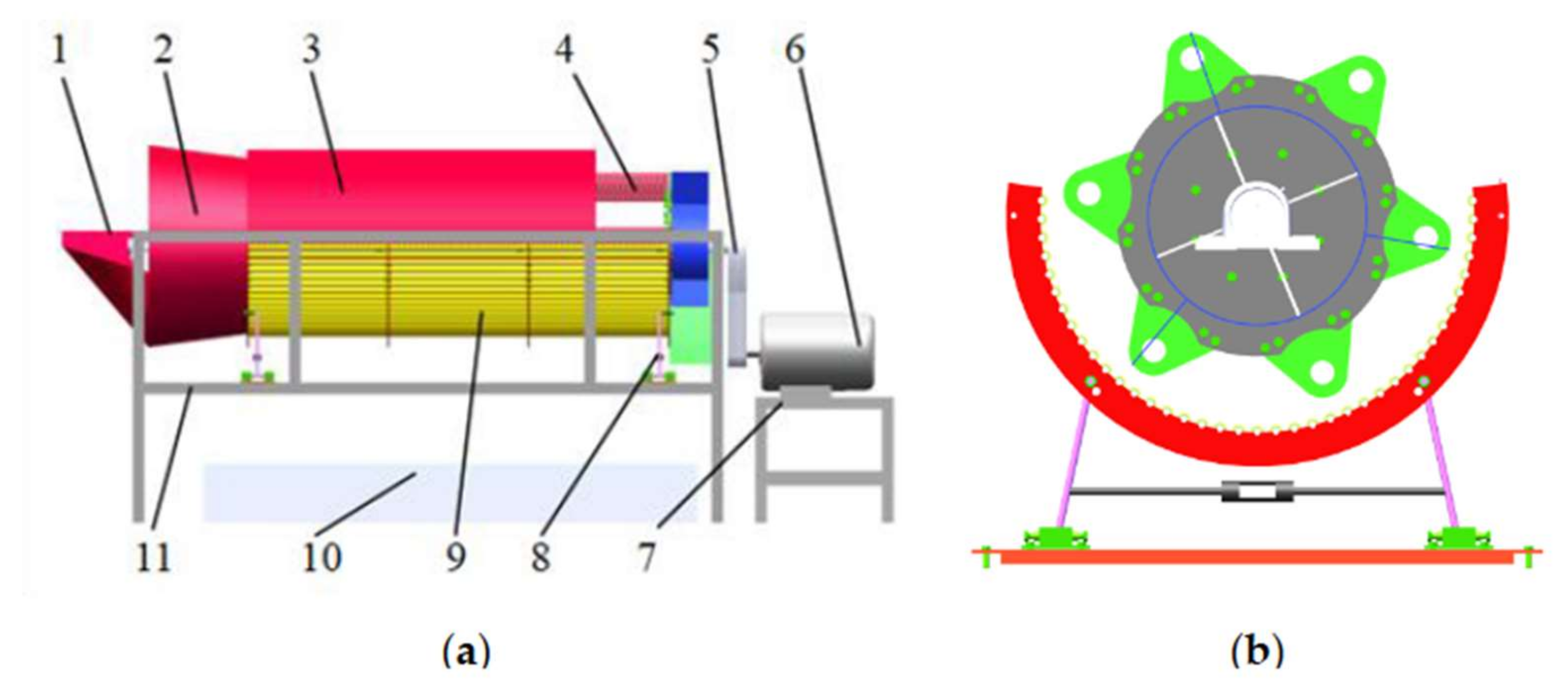
2.1. Complete Machine Structure

Based on the existing design methods of threshing devices, this study used Hertz contact theory and D‘Alembert’s principle to design the threshing device. The structure of the longitudinal axial flow staggered millet flexible threshing device is shown in Figure 1. It is mainly composed of a feeding inlet, “staggered” threshing drum, top cover, micro rotating circular tubular concave screen, frequency conversion motor, receiving box, and frame. Among them, the “staggered” threshing drum is mainly composed of a conical spiral feeding part and “staggered” flexible threshing part. The conical spiral feeding part is mainly used to transport compressed grain logistics. The “staggered” threshing element material is rubber, and its section shape is gear like. It is arranged on the whole threshing drum in such a way that two adjacent threshing units are staggered by one tooth in turn, so it is called a “staggered tooth” threshing drum. The threshing unit on the “tooth stagger” threshing drum can be well matched with the ear, and has good milling and threshing performance for the millet. A deflector is installed on the inner surface of the drum top cover, which is conducive to the axial transportation of millet materials. The micro rotating circular tube concave screen is mainly composed of a circular tube screening unit that can rotate around its own fixed axis and a micro support device. The rotary tubular screening unit and the “staggered” threshing unit cooperate to form the principle of grinding and threshing. The micro motion support device can perform reciprocating micro motion along the horizontal direction. Compared with the traditional fixed concave screen, the vibration formed in the threshing process makes the grain layer fluffy, which is more conducive to the separation of millet and reduce the entrainment loss. A receiving box is placed at the lower part of the device to collect the effluent, which is convenient for testing and analysis.

2.2. Working Principle

During operation, the millet plant is fed evenly and continuously by the conveyor belt at the feeding inlet. The shaft of the threshing drum is driven by the motor to rotate. The conical spiral feeding head at the front end of the “staggered” threshing drum gradually transports and compresses the loose grain plants and forcibly pushes them to the threshing chamber. Under the combined action of the continuous feeding of materials in the threshing chamber and the deflector on the inner surface of the top cover, the grain moves spirally along the axial direction of the drum. At the same time, the material layer is squeezed in the threshing chamber, and the threshing process is completed under the joint action of the “staggered tooth” threshing unit of the threshing drum and the rotary tubular screening unit on the concave screen. The adjacent rotary tubular screening unit of the concave screen can rotate around its own fixed axis under the action of grain logistics. The friction generated by rotation is conducive to the separation of millet agglomerates and grain on the ear, which can further increase the depurification rate and reduce the millet agglomerates rate. The concave screen is added with a micro motion support device. During threshing, the concave screen is subjected to the continuous reaction force exerted by the millet plant, and then the concave screen performs reciprocating micro motion in the horizontal direction. The micro motion will weaken the impact force accompanying the threshing process, increase the fluffy degree of the grain layer, further increase the separation rate of the grain passing through the concave screen, and then the grain falls into the aggregate box. The threshed millet stalks and miscellaneous residues are discharged out of the machine through the straw discharge board.

2.3. Key Component Design

2.3.1. The Design of Threshing Drum

The structure of the threshing drum is shown in Figure 2.
In order to balance the threshing effect and working load of the threshing device [26], the length of the drum is designed according to Formula (1).
L 1     q 1 q 0
In the formula, L 1 is total length of threshing drum, m; q 1 is the feeding amount of the threshing device, kg/s; q 0 is the feeding amount per unit length of the threshing element, 0.8~0.9 kg/(s·m).
When calculating the length of the threshing drum, the feeding amount must be determined first. According to the research of Zhalnin [27], the density of grain in the threshing gap is jointly affected by the feeding amount and the length of the threshing drum. This also affects the damage rate of millet. Therefore, the feeding amount should take a reasonable value. The feeding amount of the threshing device is 1.5 kg/s, which can be obtained from Formula (1), and the value range of the total length of the threshing drum is 1.67~1.875 m. Comprehensively, the length of the threshing drum in this design was 1.8 m.
In order to solve the winding problem of millet plants on the threshing drum, the circumference of the threshing drum must be greater than the length of millet plants. Through the calculation of the length of millet plants in this test, it can be seen that the length of millet plants is between 1000 and 1100 mm. It is found that the calculation formula of the roller diameter [28] is
D 1     1.5 L 2 π
In the formula, D 1 is total length of threshing drum, m; L 2 is the feeding amount of the threshing device, kg/s.
According to Formula (2), the diameter of the drum is 477~525 mm. Comprehensively, the diameter of threshing drum in this design is 500 mm.

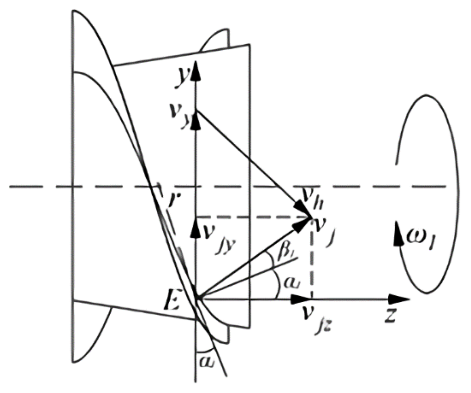
2.3.2. The Design of Conical Spiral Feeding Head

The function of the conical spiral feeding head is to compress the grain plants and push them into the threshing chamber so that the grains can spiral around the threshing drum under the action of the deflector.
The conical spiral feeding head will produce high centrifugal force and friction in the process of rotary feeding. The conical spiral feeding head rotates at an angular speed of. The speed analysis of grain at any point e of the conical spiral feeding head is shown in Figure 3.
The Figure 3 shows v y is the centripetal speed of grain on the conical spiral feeding head, and the direction is pointing to the rotation center along point E; v h is the sliding speed of grain on the conical spiral feeding head, and the direction is the tangent direction parallel to the spiral line at point E; v j is the absolute speed of grain on the conical spiral feeding head, and the direction is the deflection angle along the horizontal direction α 1   +   β 1 of point E, where α 1 is the spiral angle of the conical spiral feeding head and β 1 is the friction angle of grain on the conical spiral feeding head, which is measured to be 19°; v j z is the partial speed of the absolute speed of grain on the conical spiral feeding head on the shaft, and the direction is parallel to the z shaft; v j y is the absolute speed of grain on the conical spiral feeding head and the partial speed on the y shaft, and the direction is parallel to the y shaft. It can be obtained from the speed analysis diagram in Figure 3.
v y   =   ω 1 r μ 1   =   tan β 1 v y v j   =   sin 90 ο   +   β 1 sin α 1 v h v y   =   sin 90 ο     α 1     β 1 sin 90 ο   +   β 1 v j z   =   v j cos α 1   +   β 1 S   =   2 π r tan α 1 ω 1   =   π n 1 30
In the formula, μ 1 is the dynamic friction coefficient between grain and conical spiral feeding head; r is the radius of the gyration of grain at point e; S is the pitch length of the conical spiral feeding head, mm; n 1 is the rotating speed of the conical spiral feeding head, r·min−1.
From Formula (3)
v j z   =   n 1 S 60 cos 2 α 1 1     μ 1 tan α 1
According to Formula (4), if we want to move the grain along the axial direction, v j z > 0 , we need to meet 1     μ 1 tan α 1 > 0 , that is, tan α 1 < cot β 1 ; therefore, α 1 < 90 °     β 1 , α 1 < 71 ° , select the helix angle α 1   =   30 ° .

2.3.3. The Design of “Staggered Teeth” Threshing Element

The “staggered teeth” threshing element designed in this study and its assembly relationship on the drum are shown in Figure 4. The utility model comprises a “staggered” rubber roller, a spoke, an arc-shaped fixing plate, and a bolt group.
The arrangement of threshing elements is “staggered type”, which has the following advantages. First, the contact mode between threshing element and millet during threshing is surface contact. Compared with the line contact of traditional threshing element, the contact area is larger and the shear force on the ear is smaller [29]. The millet agglomerates is less likely to break from the spike stalk, so the millet agglomerates rate is also smaller. Second, this arrangement will cause grooves on the outer surface of the threshing elements. During threshing, there will be a pressure difference between the ears inside and outside the groove, which is conducive to the separation of grains and grain yards, and can optimize the threshing effect. Third, the concave convex arc caused by this arrangement can increase the friction force on the millet, which is conducive to improving the threshing rate of the millet and reducing the undelivered net loss rate.

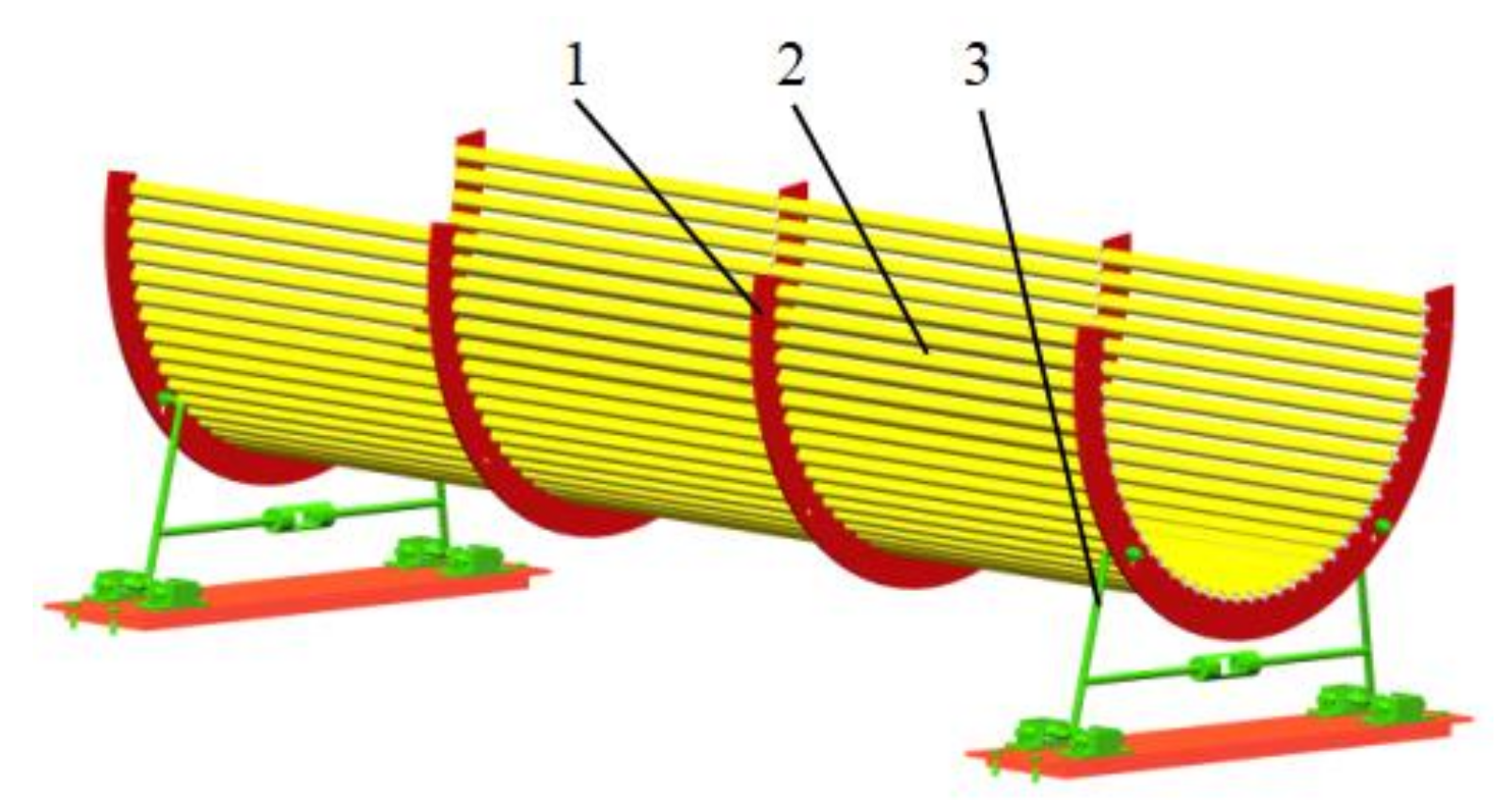
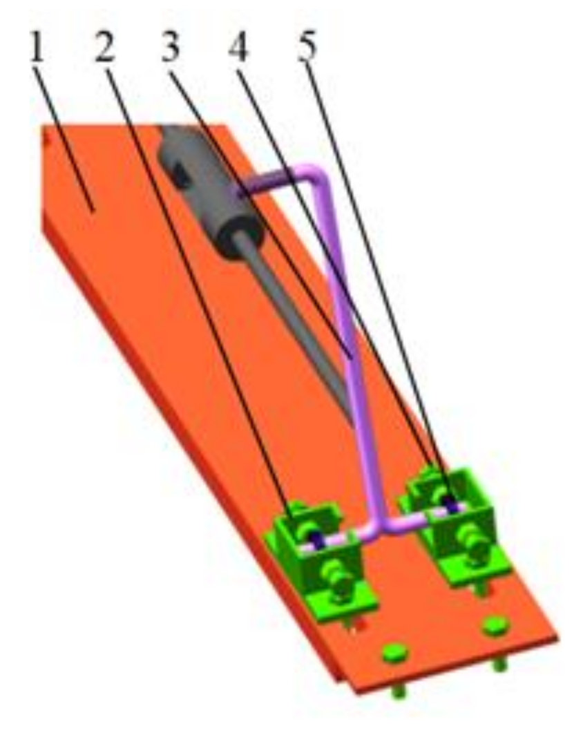
2.3.4. Structural Design of Micro Motion Rotary Tubular Concave Screen

The grid bar of the traditional grid concave screen is a cuboid [30]. During threshing, the shear force of the edge of the cuboid on the ear will cause the grain yard to break from the ear handle. It is also easy to cause damage to the grain of millet, so the traditional grid concave screen has a high grain stacking rate and damage rate. In view of the above problems, this paper designed a micro rotating circular tube concave screen, and its structure is shown in Figure 5. The micro rotary tube concave screen is composed of a hollow tube rotary screening unit and a concave screen support device.
The calculation formula for the diameter of the micro rotating circular tubular concave screen [31] is
D 2   =   D 1   +   2 δ
In the formula, δ is clearance between micro rotating circular tubular concave screen and drum, mm.
The clearance between the micro rotating circular tubular concave screen and the drum is 10 mm, and the diameter of the micro rotating circular tubular concave screen is 510 mm.
The structure of the hollow circular tube rotary screening unit is shown in Figure 6. The material of the hollow round pipe is polyurethane, which has high strength, tear resistance, wear resistance, and other characteristics [32]. The hollow tube is installed on the outermost layer of the rotary screening unit, and the ball support ring is located between the hollow tube and the support shaft. The hollow tube rotary screening unit has the following advantages: first, the hollow tube can rotate around its own axis, so the rolling effect is better when it is matched with the roller. Second, the sieve hole formed between the hollow round tubes is a long hole, which is conducive to the millet grains falling off the grain yard and directly falling into the receiving box, increasing the separation rate of the millet. Third, compared with the cuboid grid, the material of the hollow tube is flexible and has a larger contact area with the ear of grain. Therefore, the impact force and shear force of the hollow tube on the ear are smaller, which reduces the damage rate of the millet. Fourth, compared with the traditional grid concave, when the concave screen has the same size and the same number of rotations, the number of collisions between the hollow tube and the hollow tube screening unit is lower, so the grain damage rate is reduced.
The structure of concave screen support device is shown in Figure 7. Driven by the grain logistics, the horizontal displacement wheel drives the concave screen to move slightly left and right. The limit displacement is controlled by the micro adjustment bolt. The isosceles connecting rod ensures the stability of the support device. The threshing clearance range is 5~20 mm, which is adjusted by the opening and closing angle of the isosceles connecting rod.

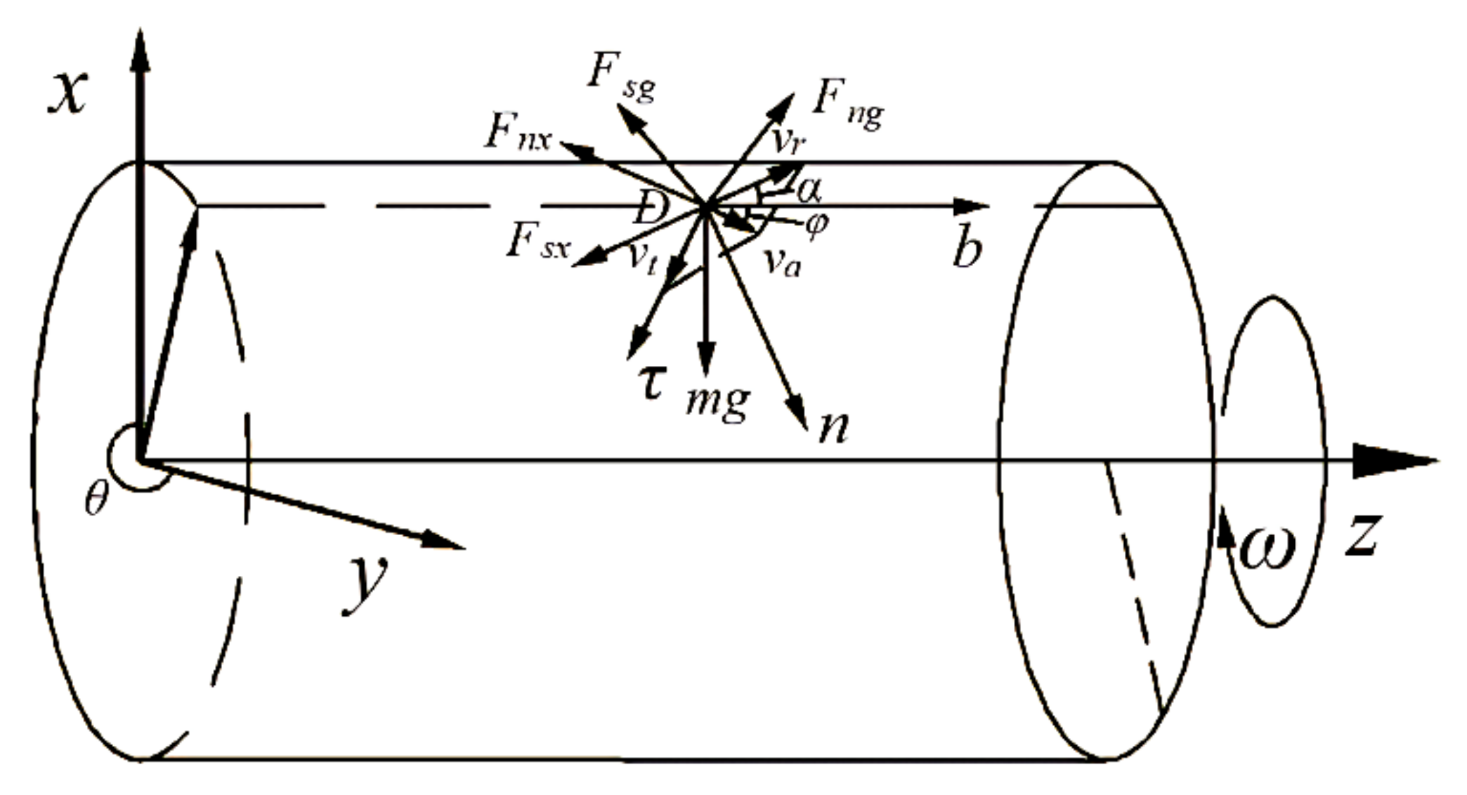
2.3.5. Dynamic Analysis of Millet on the Side of Top Cover

The dynamic model of the material on the top cover side is established by applying the Hertz contact theory and D‘Alembert’s principle, and the force analysis of the material moving to the top cover side at any position D is carried out, as shown in Figure 8.
In the figure, F s g is the friction force between the cover plate and the material, and F s x is the friction force between the rubber threshing element and the material. Let the relative angular displacement between the material and the drum be θ , and the axial displacement be z , θ π , 2 π ,   θ and z , which are all functions of time t . Then there is
m R θ 2   =   f 1 F n x sin α sin ϕ     m g sin θ     F n x cos ϕ m R θ   =   F n x sin ϕ     f 3 F n g sin ϕ   +   f 1 F n x sin α cos ϕ     F n g cos ϕ   +   m g cos θ m z   =   F n g sin ϕ     f 3 F n g cos ϕ     f 1 F n x cos α
In the formula, f 3 is the dynamic friction coefficient between the material and concave plate; ϕ is the helix angle of the material relative to the cover plate, °.
From the above theoretical model, it can be concluded that the effect of the threshing element and concave plate on material in axial flow threshing space is not only related to the gravity of material, the friction characteristics between threshing element, top cover, and concave screen and material, the structural parameters of threshing element, but also related to the movement of the material in the threshing space.

3. Results

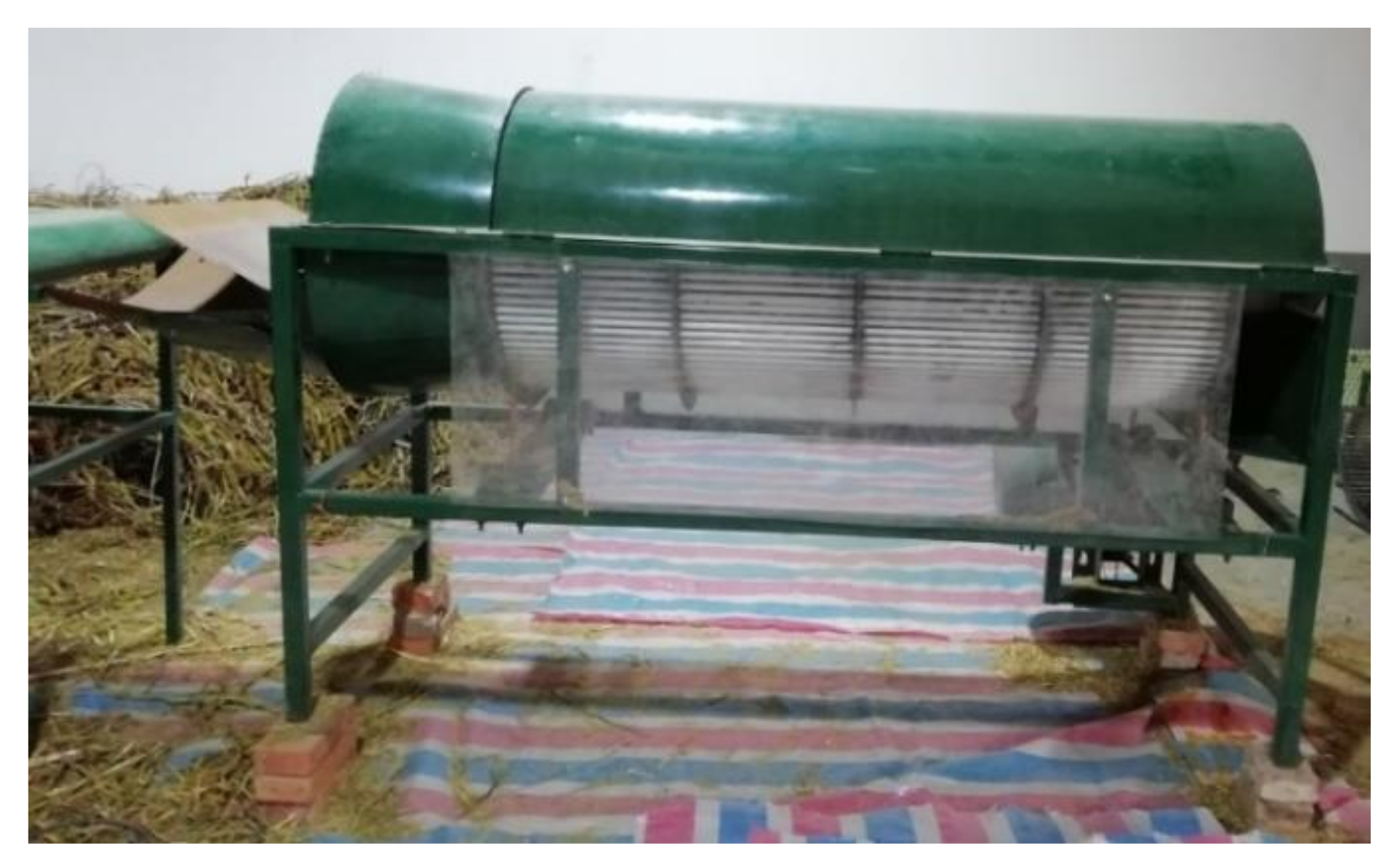
3.1. Test Materials and Equipment

The millet variety used in this experiment was Yugu 23, and its morphological structure is shown in Figure 9.
The basic parameters of millet are shown in Table 1.
The real object of the longitudinal axial flow staggered millet flexible threshing device test-bed is shown in Figure 10.

3.2. Test Purpose

Through the single factor experiment on the threshing device, it was determined that the key influencing factors on the millet agglomerates rate, damage rate, and non threshing undelivered net loss rate were: feeding amount, drum speed, and threshing clearance. The optimal level of each factor was determined, in which the optimal level range of feeding amount is 0.8~1.8 kg/s, the optimal level of drum speed is 650~950 r·min−1, and the optimal level of threshing clearance is 8~16 mm. In order to further explore the joint influence law of the main threshing parameters on threshing effect, an orthogonal regression rotation combination design experiment was adopted to achieve the purpose.

3.3. Test Method

Before the test, calculate and weigh the grain amount of a single test according to the feeding amount, and then lay the millet plants evenly parallel to the feeding and conveying direction. The conveyor belt shall reserve a 3 m long acceleration area. Adjust the rotating speed of threshing drum to meet the test requirements. After its operation is stable, start the conveyor belt to complete the process of conveying, feeding, threshing separation, and receiving.
A regression orthogonal rotation combination experimental design was adopted [33,34]. Taking the feeding amount A, drum speed B, and threshing clearance C as test factors and millet agglomerates rate y 1 , undelivered net loss rate y 2 , and damage rate y 3 as evaluation indexes, 23 groups of tests were completed. The test was carried out in accordance with the national standard GB/T 5982-2017 thresher test method. Each test was repeated three times, and the test results were taken as the average value. The better range of each factor level is determined according to the single factor test, and the factor level coding table is shown in Table 2.
Referring to the national standard GB/T 5982-2017 test method for the thresher, the calculation formulas of millet agglomerates rate y 1 , undrained undelivered net loss rate y 2 , and damage rate y 3 .
y 1   =   m 1 m × 100 %
y 2   =   m 2 m × 100 %
y 3   =   m 3 m 0 × 100 %
In the formula, m 1 is the grain weight of millet agglomerates in the mixture of stripped products, g; m 2 is the loss of grain quality without threshing, grain remaining on the ear discharged from the grass outlet, g; m 3 is the mass of damaged grain in the sample, g; m is the total grain mass, g; m 0 is the total mass of grain sampled, g.

3.4. Analysis of Test Results

The test scheme and its results are shown in Table 3. Among them, x 1 , x 2 , and x 3 correspond to the coding values of A, B, and C respectively.
The software design expert 10.0.7 was applied to carry out multiple regression analysis on the test data. The quadratic model of millet agglomerates rate y 1 , undelivered net loss rate y 2 , and damage rate y 3 was significant (p < 0.0001). The regression coefficient was F-tested under the confidence of 0.05. The simplified regression equation obtained after excluding the insignificant items as follows:
y 1   =   3.54     0.698 x 1   +   1.171 x 2     0.590 x 3   +   0.593 x 2 x 3   +   0.566 x 2 2   +   0.474 x 3 2
y 2   =   1.51   +   0.085 x 1     0.084 x 2   +   0.043 x 3   +   0.045 x 1 x 2     0.068 x 1 x 3   +   0.077 x 1 2   +   0.048 x 2 2   +   0.041 x 3 2
y 3   =   0.48   +   0.11 x 1   +   0.23 x 2     0.106 x 3   +   0.081 x 1 x 2   +   0.074 x 1 2   +   0.106 x 2 2

3.4.1. Analysis of Variance of Regression Model

The analysis of variance of Formulas (10)–(12) was carried out, and the analysis results are shown in Table 4. It can be seen from the table that the model mismatches of the three indicators y 1 , y 2 , and y 3 were p > 0.05, indicating that the model fitting effect of the three indicators is good. The regression equation of indicator is p < 0.0003, and the regression equation of indicators and is p < 0.0001, indicating that the regression equation was extremely significant.
The test results of partial regression coefficient of regression equation show that the primary and secondary relationships of various factors on millet agglomerates rate y 1 and damage rate y 3 were drum speed, feeding amount, and threshing clearance. The primary and secondary relationships of each factor on the non threshing undelivered net loss rate y 2 were feeding amount, drum speed, and threshing clearance.

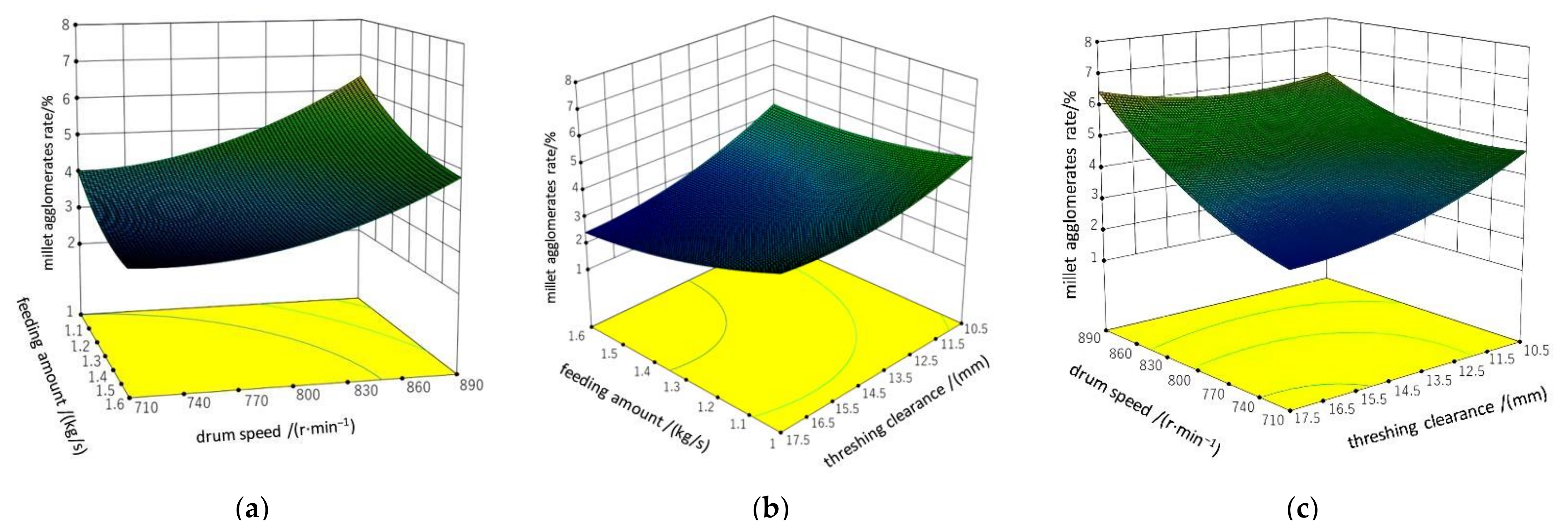
3.4.2. Analysis of the Influence of Various Factors on the Millet Agglomerates Rate

The relationship surface between each factor and millet agglomerates rate y 1 is shown in Figure 11. As can be seen from Figure 11a, the drum speed increased from 710 r·min−1 to 890 r·min−1, and the millet agglomerates rate showed a gradual increasing trend. With the increase of the rotating speed of the drum, the speed and acceleration of the millet plant in the threshing and separation space became larger, the resultant force of the millet agglomerates on the ear became larger, the millet agglomerates and the ear handle were easier to break, and the broken millet agglomerates were easier to pass through the concave screen and fall into the aggregate box, resulting in the increase of the millet agglomerates rate. The drum speed remained unchanged at a certain level, the feeding amount increased from 1 kg/s to 1.6 kg/s, and the millet agglomerates rate decreased gradually. With the increase of feeding amount, more grains entered the separation space per unit time, resulting in the increase of grain logistics density, the proportion of ear millet agglomerates subjected to friction from each other in the threshing process increased, and the resultant force was gentler, which reduces the possibility of millet agglomerates breaking from ear head. At the same time, with the increase of grain logistics density, the broken millet agglomerates do not easily pass through the concave screen, and continue to be threshed by grinding in the threshing separation space, which is further conducive to the reduction of millet agglomerates rate.
As can be seen from Figure 11b, as the threshing gap increased from 10.5 mm to 17.5 mm, the millet agglomerates rate gradually decreased. With the increase of threshing clearance, the grinding and rubbing effect of grain in the threshing space decreased, the rubbing force of millet agglomerates of ear decreased, and the possibility of millet agglomerates and ear fracture decreased. At the same time, with the increase of threshing clearance, the movement space of grain in the threshing space increased, and the millet agglomerates weight was lighter, which is easier to be in the upper layer of the threshing space, which can further reduce the millet agglomerates rate.
As can be seen from Figure 11c, when the threshing clearance is fixed to a certain level, the millet agglomerates rate also decreased gradually with the decrease of drum speed, indicating that there is a positive correlation between drum speed and millet agglomerates rate.

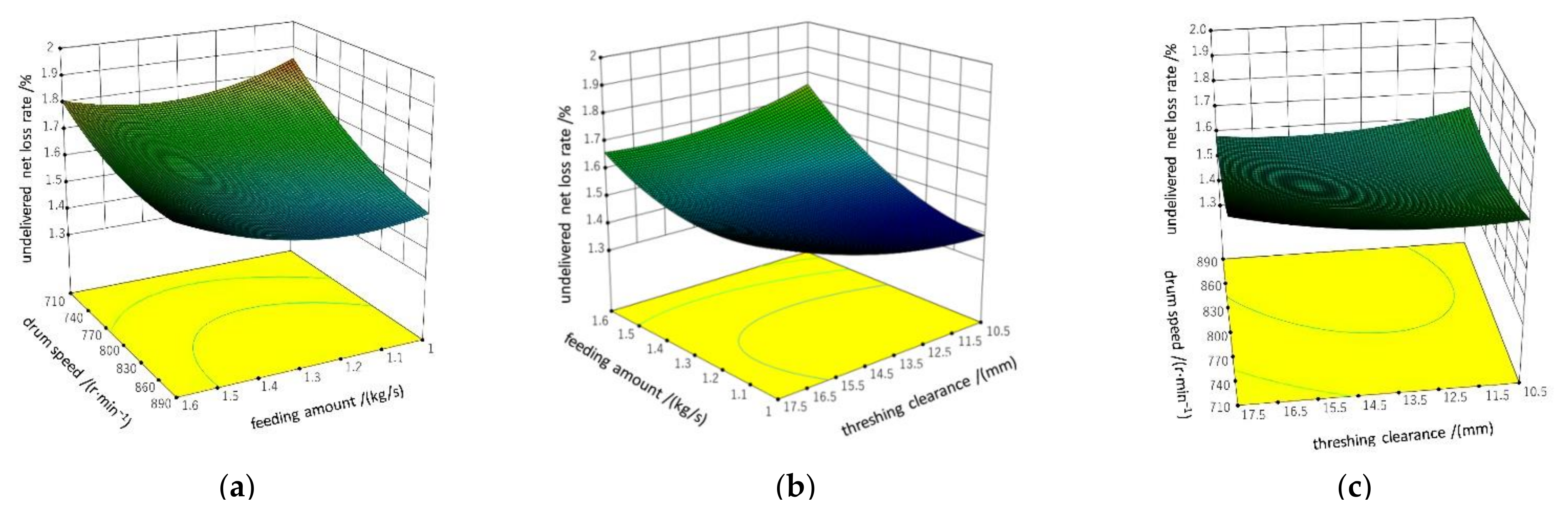
3.4.3. Analysis on the Influence of Various Factors on Undelivered Net Loss Rate

The relationship surface between each factor and undelivered net loss rate is shown in Figure 12. As can be seen from Figure 12a, when the drum speed increases from 710 r/min−1 to 890 r/min−1, the undelivered net loss rate of non-stripping tended to decrease gradually. With the increase of drum speed, the intensity and frequency of grinding and rubbing of grains in the threshing space gradually increased, and the threshing effect on grains was further enhanced. Millet grains more easily fall off from the ear, which is conducive to reducing the undelivered net loss rate of millet. When the rotating speed of the fixed drum reached a certain level, the feeding amount increased from 1 kg/s to 1.6 kg/s, and the undelivered net loss rate gradually increased. With the increase of the feeding amount, the grain logistics density in the threshing space increased, the threshing element did not thresh the grain completely, and the rubbing force on the ears between the grain layers decreased, resulting in the increase of the undelivered net loss rate.
As can be seen from Figure 12b, as the threshing gap increased from 10.5 mm to 17.5 mm, the undelivered net loss rate of non threshing decreased gradually. This is related to the structure of the concave screen designed in this paper. The threshing gap increased, the resultant force of the contact between the millet ear in the threshing unit and the screening unit decreased in the axial direction, the acceleration of the grain logistics in the axial direction decreased, the time of the grain logistics in the threshing space became longer, and the threshing was more sufficient, which is conducive to the reduction of the undelivered net loss rate of non threshing.
It can be seen from Figure 12c that when the threshing clearance was fixed to a certain level, the non threshing loss decreased first and then increased with the increase of drum speed, indicating that there was a negative correlation between drum speed and undelivered net loss rate.

3.4.4. Analysis of Influence of Various Factors on Damage Rate

The relationship surface between each factor and damage rate y 3 is shown in Figure 13. As can be seen from Figure 13a, the damage rate increased significantly as the drum speed increased from 710 r/min−1 to 890 r/min−1. With the increase of the rotating speed of the drum, the intensity and frequency of the impact and grinding of the threshing element on the grain flow located in the threshing separation space increase, resulting in the increase of the damage rate of millet grains. When the rotating speed of the drum was fixed to a certain level, the feeding amount increased from 1 kg/s to 1.6 kg/s, and the damage rate increased slowly, but the increase was small. With the increase of feeding amount, the grain logistics density increased, which leads to the increase of the resultant force of rolling and rubbing of the ear being direct contact with the threshing element, and the enhancement of rolling and rubbing effect leads to the increase of the damage rate.
As can be seen from Figure 13b, as the threshing clearance increased from 10.5 mm to 17.5 mm, the damage rate gradually decreased. The reason is that with the increase of threshing clearance, the grinding and rubbing effect of grains located in the threshing space decreased, and the millet ears had a larger buffer space when impacted by the roller, resulting in a smaller damage rate.
It can be seen from Figure 13c that when the fixed threshing gap was at a certain level, the drum speed increased and the damage rate increased, indicating that the drum speed was positively correlated with the damage rate.

3.4.5. Parameter Optimization Analysis of Threshing Device

Learn the theory of multivariate statistical analysis and establish a mathematical model to optimize and analyze the millet agglomerates rate, undelivered net loss rate and damage rate.
(1)
Objective function
Using the mathematical model established in Formulas (10)–(12), the millet agglomerates rate, undelivered net loss rate and damage rate are minimized under constraints, and the objective functions min y 1 , min y 2 , and min y 3 are established.
(2)
Constraints
Indexes y 1 , y 2 , and y 3 shall be greater than 0 while obtaining the minimum value respectively. The coding value of each factor must be within the range selected by the test, and the established constraints are
y j 0 ,   j   =   1 , 2 , 3 1.682 x i 1.682 , i   =   1 , 2 , 3
The regression mathematical model was established according to Formula (13) and optimized by using design expert 10.0.7 software. The weights of millet agglomerates rate y 1 , undelivered net loss rate y 2 , and damage rate y 3 were 0.4, 0.3, and 0.3 respectively. The optimum parameter combination was optimized and determined as follows: the feeding amount was 1.3 kg/s, the rotating speed of the drum was 762 r/min−1, and the concave clearance was 15 mm. At this time, the millet agglomerates rate of millet was 2.92%, the undelivered net loss rate of undrained grain was 1.58% and the damage rate was 0.37%.

3.5. Verification Test

The optimal parameter combination of software optimization did not appear in the test, so it is necessary to carry out verification test. The results are shown in Table 5. The verification test results are close to the software optimization results. Within the allowable error range, it is considered that the test results are consistent with the software prediction results.

4. Conclusions

(1)
Aiming at the existing problems of millet threshing, a longitudinal axial flow staggered flexible threshing device for millet was designed. Compared with traditional threshing devices such as peg-tooth axial flow threshing and separating unit, bar threshing device, and 5GJT-400 millet thresher, it has the following advantages: the threshing element material of the drum adopts wear-resistant rubber, and the threshing process is gentler. The concave screen is a micro rotating circular tube concave screen. The concave screen screening unit can rotate, and the concave screen support device can micro move. The whole system uses the grinding principle to thresh. The device can meet the requirements of low millet agglomerates rate, low undelivered net loss rate, and low damage rate.
(2)
The key structural parameters of the threshing drum and flexible micro motion concave were designed and analyzed, and the dynamic analysis of grain located on the side of top cover at any time was carried out by using the principle of d’Alembert. The results showed that the effect of the threshing element of the drum and screening unit of the concave screen on grain and the gravity of grain, the friction characteristics between grains, the structural parameters of the threshing element and screening unit, and the motion track of grain in the separation space acceleration are related.
(3)
Through the analysis of the test results, it was found that the primary and secondary relationships of each factor on the millet agglomerates rate and damage rate were drum speed, feeding amount, and threshing clearance. The primary and secondary relationships of the influence of various factors on the undelivered net loss rate of non-threshing were feeding amount, drum speed, and threshing clearance.
(4)
For millet plants with grain moisture content in the range of 14.9~17.4%, the optimal parameter combination of longitudinal axial flow staggered millet flexible threshing device is as follows: feeding amount of 1.3 kg/s, drum speed of 762 r/min−1 and concave clearance of 15 mm. At this time, the millet agglomerates rate of millet was 2.92%, the undelivered net loss rate of non-threshing was 1.58%, and the damage rate was 0.37%.

Author Contributions

Conceptualization, X.L.; methodology, W.Z.; software, W.W.; validation, X.L., W.W. and Y.H.; investigation, Y.H.; data curation, W.Z.; writing—Original draft preparation, W.Z.; writing—Review and editing, X.L.; visualization, X.L.; supervision, X.L. All authors have read and agreed to the published version of the manuscript.

Funding

This research was funded by National Key Research and Development Plan Key Projects, grant number 2016YFD0701802.

Institutional Review Board Statement

Not applicable.

Informed Consent Statement

Not applicable.

Data Availability Statement

The data presented in this study are available on request from the corresponding author.

Conflicts of Interest

The authors declare no conflict of interest.

References

  1. Jia, G.Q.; Diao, X.M. Current Status and Perspectives of Innovation Studies Related to Foxtail Millet Seed Industry in China. Sci. Agric. Sin. 2022, 55, 653–665. [Google Scholar]
  2. Li, S.G.; Liu, F.; Liu, M.; Cheng, R.H.; Xia, E.J.; Diao, X.M. Current Status and Future Prospective of Foxtail Millet Production and Seed Industry in China. Sci. Agric. Sin. 2021, 54, 459–470. [Google Scholar]
  3. Li, S.G.; Liu, F.; Liu, M.; Zhao, Y.; Wang, H.J. Current situation, development trend and Countermeasures of millet industry in China. Agric. Mod. Res. 2014, 35, 531–535. [Google Scholar]
  4. Li, Y.H.; Guo, E.H.; Fan, H.P.; Wang, L.X.; Zhang, A.Y.; Liu, X.; Cheng, L.P. Discussion on the development of millet industry. Mod. Agric. Sci. Technol. 2019, 22, 28–29. [Google Scholar]
  5. Jia, G.; Liu, X.; Schnable, J.C.; Niu, Z.; Wang, C.; Li, Y.; Wang, S.; Wang, S.; Liu, J.; Guo, E. Microsatellite Variations of Elite Setaria Varieties Released during Last Six Decades in China. PLoS ONE 2015, 10, e0125688. [Google Scholar] [CrossRef] [Green Version]
  6. Tang, X.H.; Jin, C.Q.; Zhang, G.T.; Guo, Z.; Zhao, N.; Xu, B. Research status of threshing and separation device of combine harvester in China. Res. Agric. Mech. 2022, 44, 1–9. [Google Scholar] [CrossRef]
  7. Yang, L.Q.; Wang, W.Z.; Zhang, H.M.; Li, L.H.; Wang, M.M.; Hou, M.T. Improved design and bench test of tangential transverse axial flow corn threshing system. Trans. Chin. Soc. Agric. Eng. 2018, 34, 35–43. [Google Scholar]
  8. Tang, Z.; He, J.Z.; Zhou, Y.P.; Liu, J.B. Threshing parameter test and analysis of multi drum threshing and separation device. Res. Agric. Mech. 2017, 37, 153–157. [Google Scholar]
  9. Miu, P.I.; Kutzbach, H.-D. Modeling and simulation of grain threshing and separation in axial threshing units: Part II. Application to tangential feeding. Comput. Electron. Agric. 2008, 60, 105–109. [Google Scholar] [CrossRef]
  10. Gao, Y.E. Brief introduction of grain combine production abroad. Grain Oil Process. Food Mach. 1987, 5, 18–20. [Google Scholar]
  11. Lu, W.T.; Wang, R.X.; Deng, Z.G. Research status and Prospect of threshing technology for combined harvest of coarse grains. China J. Agric. Chem. 2017, 38, 11–16. [Google Scholar] [CrossRef]
  12. Wu, H.Y.; Liu, H.X.; Yang, Z.J.; Li, X.H.; Jiao, H.; Wang, C.J.; Zhang, G.J. Analysis on the current situation and development trend of millet production mechanization. Agric. Technol. Equip. 2012, 12, 14–17. [Google Scholar]
  13. Arnold, R.E. Experiments with rasp bar threshing drum. J. Agric. Eng. Res. 1964, 9, 99–131. [Google Scholar]
  14. Powar, R.; Aware, V.; Shahare, P. Optimizing operational parameters of finger millet threshing drum using RSM. J. Food Sci. Technol. 2019, 56, 3481–3491. [Google Scholar] [CrossRef] [PubMed]
  15. Gummert, M.; Kutzbach, H.D.; Muhlbauer, W.; Wacker, P.; Quick, G.R. Performance evaluation of an IRRI axial-flow paddy thresher. Agric. Mech. Asia Afr. Latin Am. 1992, 23, 47–54. [Google Scholar]
  16. Xu, D.X. Preliminary analysis of longitudinal axial flow drum. J. Luoyang Inst. Agric. Mach. 1980, 1, 115–131. [Google Scholar]
  17. Wu, X.F. Analysis and Experimental Study on Relevant Mechanical Characteristics of New Millet Thresher; Shanxi Agricultural University: Taigu, China, 2005. [Google Scholar]
  18. Zhang, D.M.; Yi, S.J.; Tao, G.X.; Mao, X. Development of millet axial threshing and separation test bench. Res. Agric. Mech. 2019, 41, 62–67. [Google Scholar]
  19. Zong, W.Y.; Liao, Q.X.; Chen, L.; Li, H.T.; Huang, P. The effect of different threshing methods on rapeseed pod at the end of ripening stage. Trans. Chin. Soc. Agric. Eng. 2012, 28, 29–34. [Google Scholar]
  20. Sun, C.L.; Zuo, J.W.; Lu, F.Y.; Geng, L.X. Design and test of combined axial flow drum for oat threshing. Res. Agric. Mech. 2021, 43, 135–141. [Google Scholar]
  21. Lu, W.T. Experimental study on performance of millet threshing system. Agric. Mach. 2020, 6, 100–103. [Google Scholar]
  22. Tang, Z.; Li, Y.; Xu, L.; Li, H.; Pang, J. Experiment and evaluating indicators of wheat threshing and separating on test-bed of longitudinal axial-threshing unit. Trans. Chin. Soc. Agric. Eng. 2012, 28, 14–19. [Google Scholar]
  23. Wang, J.; Li, Z.; Hussain, S.; Lu, Q.; Song, H.; Zheng, D. Design and threshing outputs study of internal and external rotary roller buckwheat thresher. INMATEH-Agric. Eng. 2020, 60, 173–182. [Google Scholar] [CrossRef]
  24. Lachuga, Y.F.; Bur’yanov, A.; Pakhomov, V.; Chervyakov, I. Adaptation of Threshing Devices to Physical and Mechanical Characteristics of Harvested Crops. Russ. Agric. Sci. 2020, 46, 198–201. [Google Scholar] [CrossRef]
  25. Samuel, A.A.; Alice, K.A.; Seckley, E.M.; Adetunla, A.O. Development of a Threshing Device for Pearl Millet. Curr. J. Appl. Sci. Technol. 2019, 33, 1–12. [Google Scholar] [CrossRef]
  26. Fan, C.L.; Cui, T.; Zhang, D.X.; Ynag, L.; Qu, Z.; Li, Y.H. Design and test of low damage combined corn threshing and separation device. Trans. Chin. Soc. Agric. Mach. 2019, 50, 113–123. [Google Scholar]
  27. Zhalnin, E.V.; Chaplygin, M.E. Dynamics of Fractional Composition of Grain-and-Straw Mass Being Threshedin the Threshing Mechanism of a Combine Harvester. Eng. Technol. Syst. 2022, 32, 249–262. [Google Scholar] [CrossRef]
  28. Li, Y.M. Design and Analysis of Grain Combine, 1st ed.; China Machine Press: Beijing, China, 2014; pp. 34–40. [Google Scholar]
  29. Wang, Z.B.; Wang, Z.W.; Zhang, Y.P.; Yan, W.X.; Chi, Y.J.; Liu, C.Q. Design and test of longitudinal axial flow flexible hammer claw corn threshing device. Trans. Chin. Soc. Agric. Mach. 2020, 51, 109–117. [Google Scholar]
  30. Chen, M.Z.; Xu, G.F.; Wang, C.X.; Diao, P.S.; Zhang, Y.P.; Niu, G.D. Design and test of longitudinal axial flow roller combined corn flexible threshing and separation device. Trans. Chin. Soc. Agric. Mach. 2020, 51, 123–131. [Google Scholar]
  31. Wang, X.W. Study on Threshing Separation System with Adjustable Threshing Clearance; Hunan Agricultural University: Changsha, China, 2019. [Google Scholar]
  32. Wang, D.R. Development and application progress of polyurethane elastomer. China Rubber Plast. Technol. Equip. 2021, 47, 24–28. [Google Scholar] [CrossRef]
  33. Ren, L.Q. Experimental Design and Optimization, 2nd ed.; Science Press: Beijing, China, 2009; pp. 7–35. [Google Scholar]
  34. Singh, K.; Pardeshi, I.; Kumar, M.; Srinivas, K.; Srivastva, A. Optimisation of machine parameters of a pedal-operated paddy thresher using RSM. Biosyst. Eng. 2008, 100, 591–600. [Google Scholar] [CrossRef]
Figure 1. Structural diagram of longitudinal axial flow staggered millet threshing device: 1. feed inlet; 2. conical spiral feed housing; 3. top cover; 4. staggered threshing drum; 5. drive belt; 6. variable frequency motor; 7. motor support; 8. concave screen micro motion support device; 9. rotary tubular concave screen; 10. receiving box; 11. frame. (a) Assembled frame; (b) schematic diagram of combination of “staggered teeth” threshing drum and micro rotating circular tubular concave screen.
Agriculture 12 01179 g001
Figure 2. Structure diagram of threshing drum: 1. Main shaft; 2. conical spiral feed head; 3. spoke; 4. staggered threshing element; 5. grass discharge plate.
Agriculture 12 01179 g002
Figure 3. Grain speed analysis diagram of the feeding head.
Agriculture 12 01179 g003
Figure 4. Installation diagram of “staggered teeth” threshing element: 1. “Staggered” rubber roller; 2. spoke; 3. arc fixed plate; 4. bolt group.
Agriculture 12 01179 g004
Figure 5. Structural diagram of micro rotating circular tubular concave screen: 1. side arc plate; 2. hollow circular tube rotary screening unit; 3. concave screen support device.
Agriculture 12 01179 g005
Figure 6. Schematic diagram of micro rotating circular tube concave screen: 1. side arc plate; 2. hollow circular tube rotary screening unit; 3. concave screen support device. Structure diagram of hollow circular tube rotary screening unit: (a) the overall structure diagram; (b) the side view.
Agriculture 12 01179 g006
Figure 7. Structural diagram of concave screen support device: 1. plane fixing plate; 2. concave screen support base; 3. isosceles connecting rod; 4. micro adjustment bolt; 5. horizontal displacement roller.
Agriculture 12 01179 g007
Figure 8. Schematic diagram of stress on the side of the top cover.
Agriculture 12 01179 g008
Figure 9. Yugu 23 millet: (a) the figure shows the millet plant; (b) the figure shows the millet ear head; (c) the figure shows the millet agglomerates; (d) the figure shows the millet grain.
Agriculture 12 01179 g009
Figure 10. Physical drawing of the millet flexible threshing device test bench.
Agriculture 12 01179 g010
Figure 11. Influence of drum speed, feeding amount, and threshing clearance on millet agglomerates rate. (a) the picture shows the influence of drum speed and feeding amount on millet agglomerates rate; (b) the picture shows the effect of threshing clearance and feeding amount on millet agglomerates rate; (c) the picture shows the effect of threshing clearance and drum speed on millet agglomerates rate.
Agriculture 12 01179 g011
Figure 12. Influence of drum speed, feeding amount, and threshing clearance on undelivered net loss rate. (a) the picture shows the influence of drum speed and feeding amount on undelivered net loss rate; (b) the picture shows the effect of threshing clearance and feeding amount on undelivered net loss rate; (c) the picture shows the effect of threshing clearance and drum speed on undelivered net loss rate.
Agriculture 12 01179 g012
Figure 13. Influence of drum speed, feeding amount, and threshing clearance on damage rate. (a) the picture shows the influence of drum speed and feeding amount on damage rate; (b) the picture shows the effect of threshing clearance and feeding amount on damage rate; (c) the picture shows the effect of threshing clearance and drum speed on damage rate.
Agriculture 12 01179 g013
Table 1. Basic parameters of the experimental millet.
ParameterNumerical Value
Average plant length/mm1089
Average length of spike head of millet/mm185
Number of grain yards on the head of millet spike/piece90~110
Average diameter of millet agglomerates/mm8.4
Average grain diameter/mm1.48
Plant moisture content/%26.8~28.7
Grain moisture content/%14.9~17.4
Mass of 1000 grains/g2.98
Table 2. Coad of factor level.
CodeFactor
A/(kg·s−1)B/(r·min−1)C/(mm)
1.6821.895020
11.689017.5
01.380014
−1171010.5
−1.6820.86508
Table 3. Test scheme and results.
Serial NumberABCy1/%y2/%y3/%
1−1−1−15.651.80.62
21−1−15.10.710.32
3−11−15.981.420.9
411−16.021.751.31
5−1−111.050.820.20
61−112.5331.80.42
7−1117.021.550.63
81114.61.651.05
9−1.682006.10.461.52
101.682002.510.751.91
110−1.68202.401.750.35
1201.68207.61.521.04
1300−1.6825.51.540.55
14001.6825.51.540.10
150003.021.540.49
160003.491.610.48
170003.21.420.48
180004.41.480.31
190004.851.580.39
200003.120.511.42
210003.581.490.58
220002.951.510.63
230003.31.570.53
Table 4. Analysis of variance.
IndexSource of VariationSSdfMSFp
y1Regression44.0694.98.80.0003
Surplus7.23130.56
Misfit3.850.761.780.2242
Error3.4380.43
Total51.2922
y2Regression0.4490.04912.31<0.0001
Surplus0.051130.0039
Misfit0.01450.00290.630.6861
Error0.03780.0046
Total0.4922
y3Regression1.3690.1512.03<0.0001
Surplus0.16130.013
Misfit0.09250.0182.040.1762
Error0.07280.0090
Total1.5322
Table 5. Verification test results.
Test Serial NumberIndex
y1/%y2/%y3/%
Estimate2.921.580.37
Test 12.891.570.39
Test 22.911.590.41
Test 32.931.610.36
Publisher’s Note: MDPI stays neutral with regard to jurisdictional claims in published maps and institutional affiliations.

