Article

Analysis and Simulation of Wheel-Track High Clearance Chassis of Rape Windrower

1
College of Engineering, Nanjing Agricultural University, Nanjing 210031, China
2
Nanjing Institute of Agricultural Mechanization, Ministry of Agriculture and Rural Affairs, Nanjing 210014, China
*
Author to whom correspondence should be addressed.
Agriculture 2022, 12(8), 1150; https://doi.org/10.3390/agriculture12081150
Submission received: 4 July 2022 / Revised: 29 July 2022 / Accepted: 29 July 2022 / Published: 3 August 2022
(This article belongs to the Special Issue Advances in Agricultural Engineering Technologies and Application)

Abstract

:
The middle and lower reaches of the Yangtze River are the main production area of rapeseed. Small windrowers with two tracks are adopted in this area, which have lower efficiency. With the advancement of large-scale rape planting, medium and large windrowers are urgently needed; however, most medium and large windrowers are wheeled machines which have poor adaptability to sticky soil in rice–rape rotation areas. Therefore, a wheel-track high clearance chassis for rape windrower was developed. Theoretical analysis and simulation of the main performance of this chassis were investigated. Mathematical models of the relationship between the chassis eccentricity and running resistance, uphill and downhill angle and the height of obstacle were established. Then, three-dimensional modeling and dynamic simulations of a wheel-track high clearance chassis of a rape windrower in wet clay soil were carried out based on Pro/E and RecurDyn software. The simulation results indicated that when the chassis ran on flat hard road at the same speed, eccentricity had little effect on average walking speed; the coefficient variation of speed decreased with the increase of eccentricity, while the driving torque and its coefficient variation decreased first and then increased. The minimum driving torque and the coefficient variations were obtained when the eccentricities were 1484 mm and 1584 mm. Field experiments were carried out on two kinds of ground. The results showed that on flat hard road, the speed of the wheel-track high clearance rape windrower was 0~20.22 km/h, the minimum turning radius was 5.965 m; on rice stubble field with 38.7% water content, the working speed was 0~9.12 km/h, the minimum turning radius was 6.498 m, and the climbing angle was over 20°. All parameters of the wheel-track high clearance chassis met the design specifications, and the working efficiency increased over 100% compared with the existing two-tracked rape windrower. A new kind of rape windrower for the middle and lower reaches of the Yangtze River was provided.

1. Introduction

The existing chassis of rape windrowers is divided into two types: two tracked chassis and four wheeled high clearance chassis. A two tracked chassis has strong adaptability to soil, which is mainly applicable to rape windrower in the middle and lower reaches of the Yangtze River. A four wheeled high clearance chassis is mainly used for rape windrower of dry-land cultivation in northern China [1,2]. With the gradual advancement of land transfer, rape planting areas in rice–oil rotation regions of the Yangtze River Basin have been expanding, so medium and large-sized harvesting equipment is urgently needed. Most of the large-sized rape windrowers have wheeled chassis, which are not suitable for sticky and heavy soil with high moisture content. They sink and slip easily and cannot work well [3,4,5]. In this paper, a wheel-track high clearance chassis is proposed. Triangular tracks and rubber tires are combined to make full use of the high passing of the track and the flexibility of the wheel.
In China, research on wheel-track structure has mainly focused on mobile robots. Conversion mechanisms of different walking forms such as wheel, track and leg have been designed, motion equations in various states have been constructed, and various virtual prototypes have been established. The step walking performance, stability and power consumption of each walking mechanism under different working environments have been analyzed [6,7,8,9,10,11]. All these studies investigated the machines used in workshops or setting hard roads.
In recent years, in order to increase the walking performance and adaptability of agricultural machinery equipment, research on agricultural machinery chassis under various working environments has been carried out. Theses chassis were used for sugarcane harvesting, orchard plant protection and harvesting, forest land slope operation, coal mine underwater operation and so on. A triangle tracked chassis for a sugarcane harvester was designed by Bai Yuanqiang. The adaptability of a triangle track and flat track combination to slope ground was better than that of a traditional track sugarcane harvester [12]. A four triangular tracked camellia fruit picking machine with good adaptability to southern gentle slope land was developed by Cai Gangchu [13]. A two triangle tracked orchard chassis was designed by Wang Feng and the performance met the actual requirements of orchard work [14]. A wheel-track high clearance chassis of a paddy field sprayer was designed by Zeng Shan, and the theoretical analysis of steering performance was carried out. The force analysis of trapezoidal support under load was carried out to optimize the walking device. The minimum turning radius of this machine was 3380 mm [15]. A multifunctional power chassis for orchard was designed by Hao Chaohui. The turning performance, stability performance and ridge crossing performance of the chassis were analyzed theoretically. The minimum turning radius was 2000 mm and the maximum climbing angle was 24° [16]. The performance analysis of the tracked tractor climbing obstacle was carried out by Pan Guanting. The relationship between the obstacle height, slope angle and the centroid position of the tractor was obtained by simulation, and the obstacle heights under different speeds and ramp angles were also obtained [17].
Several kinds of chassis, such as four triangular tracked flat tracked chassis or two-wheeled two-tracked type chassis, are widely used for large tractors, harvesters and seeders, which provide greater ground contact and effectively reduce grounding pressure and soil damage. The John Deere 9620RX four triangular tracked tractor, C100 two-wheeled two-tracked harvester, CASE 6088 two triangular tracked two wheeled harvester and CLAAS LEXION770 two flat tracked two wheeled harvester have advantages.
It follows that research on wheeled and tracked chassis in China or abroad are mainly applied to special function robots and some farm machinery for woodland, orchards or large farms in dry land areas. However, this kind of chassis is seldom used for high clearance machines.
In this paper, a detailed analysis of the walking performance and stability performance of a high clearance chassis for rape windrower was carried out, which provided a basis for the development of large-scale rape windrowers in the Yangtze River Basin.

2. Performance and Simulation Analysis of Chassis

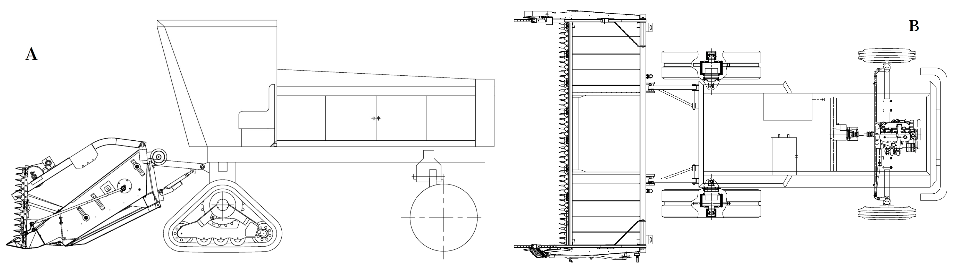
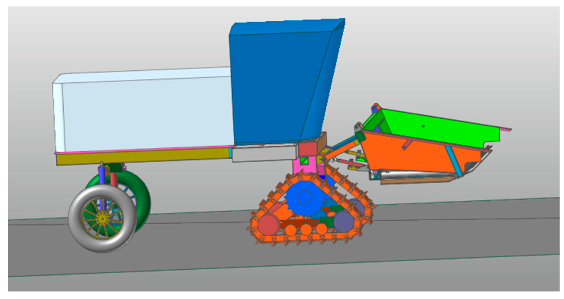
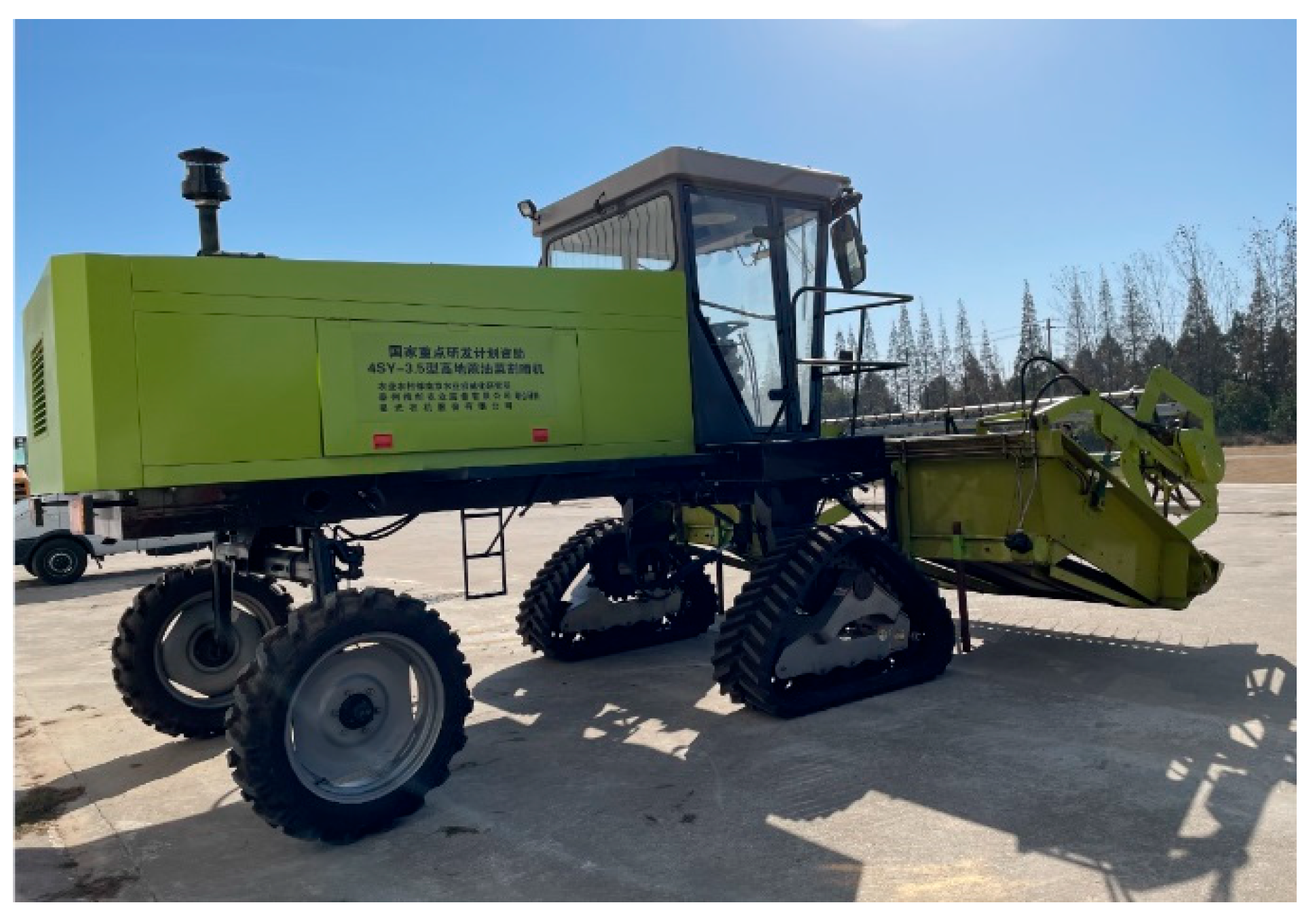
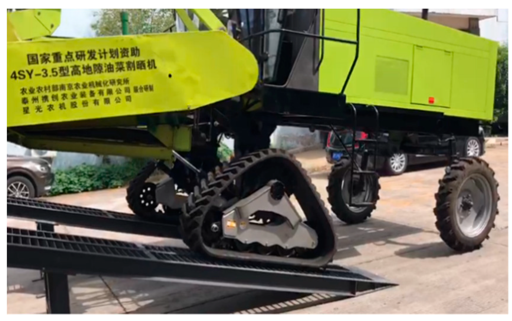
2.1. Structure and Working Principle of a Wheel-Track High Clearance Chassis for Rape Windrower

The structure of a wheel-track high clearance chassis for rape windrower is shown in Figure 1. It mainly includes two parts: swath header and wheel-track high clearance chassis. The front walking mechanisms are two triangle tracks, which are the driving parts; the back walking mechanisms of the chassis are two rubber tires which are follower wheels. The chassis is also composed of the engine, the pump motor power system, the chassis frame, the header suspension frame, and the fuel tank.
Triangular tracks are driven by a hydraulic system to pull the machine forward and backward. The steering mechanism is driven by a hydraulic system with a selector valve, which is controlled by the steering wheel in the cab. The rubber tires are deflected by the steering mechanism to steer the machine. When the machine works, the cutter cuts the crops down, which are then moved to the middle gap by the conveyor belt on both sides of the header. Therefore, the chassis not only needs the functions of walking, climbing and crossing the terrain, but also needs enough space to let the plants that have been cut lay smoothly under the chassis. The specific structural parameters and technical indicators are shown in Table 1.

2.2. Analysis of Driving Resistance

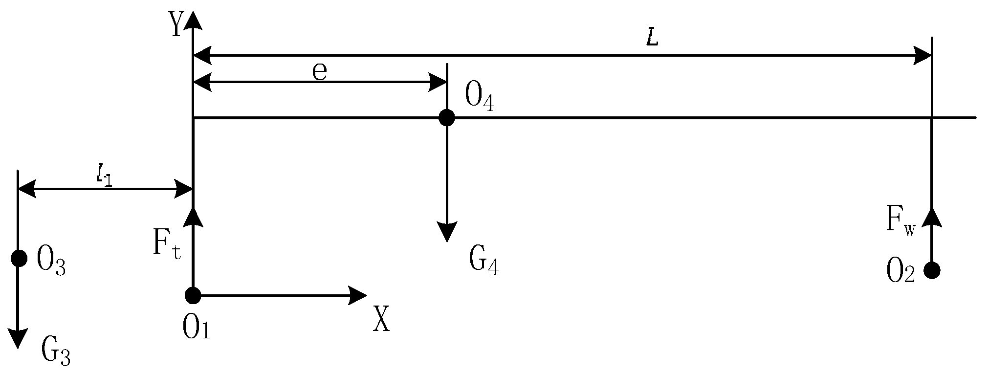
2.2.1. Analysis of Wheel and Track Load

The force diagram of the chassis frame and swath header (located in the harvesting state) on the horizontal ground is shown in Figure 2. O 1 and O 2 are, respectively, the force points of the frame on the triangular track and wheel, O 3 is the center of gravity of the header, and O 4 is the center of gravity of the chassis. Two equations are used to explain the balance at steady state, as below.
F t + F w = G 3 + G 4 G 3 l 1 + F w L = G 4 e
After calculating:
F w = G 4 e G 3 l 1 L F t = G 3 + G 4 L G 4 e + G 3 l 1 L
where l 1 is the horizontal distance between the gravity center of the swath header and the action point of the track on the frame, 1880 mm; L is wheelbase, 2950 mm; e is the eccentricity of the chassis frame (chassis frame: swath header, tires and tracks are not included), which is the horizontal distance between the gravity center of the chassis frame and the center point of the track, mm; all the eccentricities mentioned below are equivalent to e ; G 3 is the weight of header and G 4 is the weight of chassis frame, which may be taken as 10,000 N and 20,000 N, respectively.   F w , F t are the forces applied by the wheel and the track, respectively, to the frame, N.

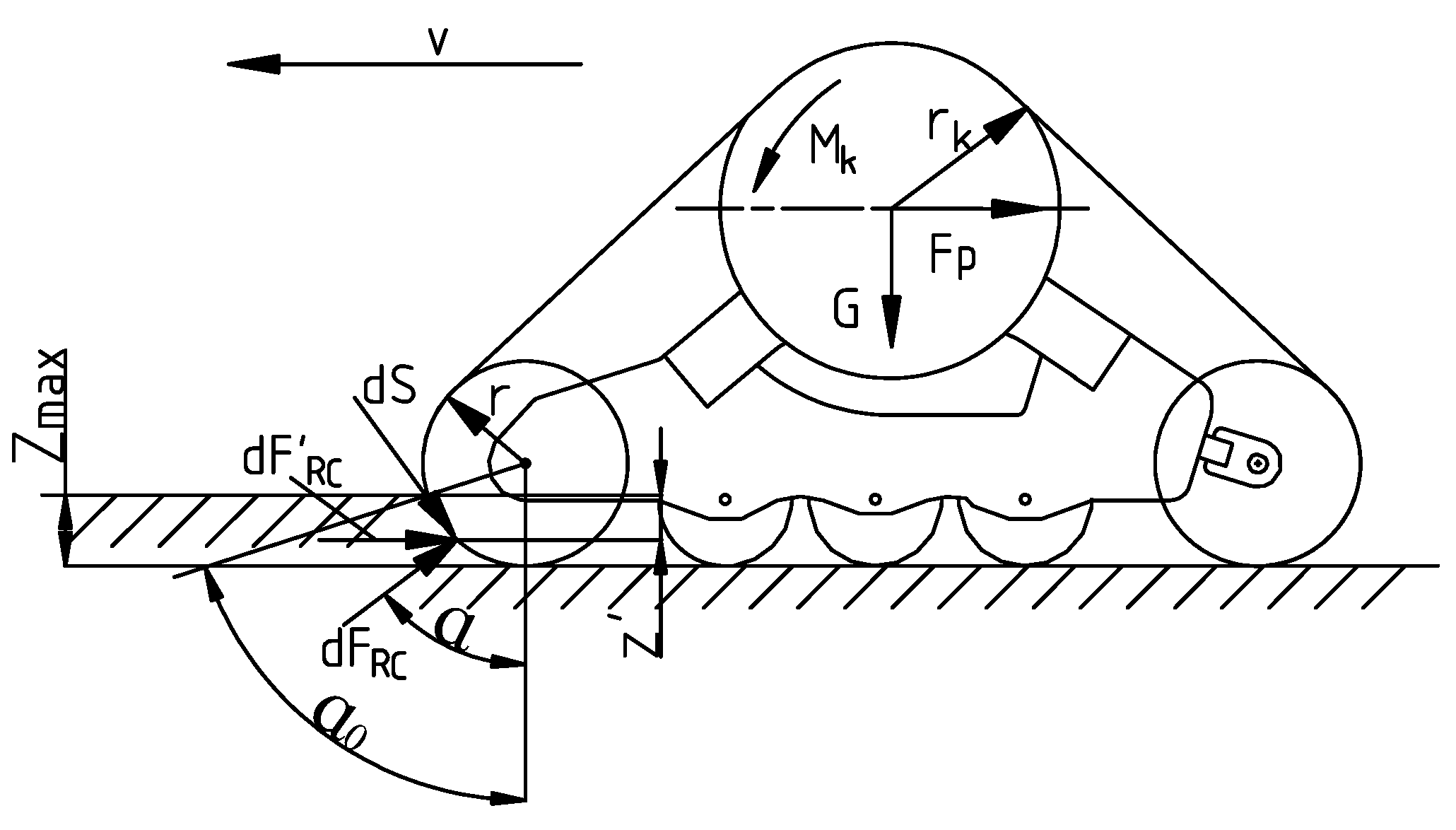
2.2.2. Analysis of Driving Resistance

When the track is running, the soil is compacted and the compaction resistance is produced on the track, which is related to the force bearing point from the chassis frame and the geometric center of the track [18,19,20,21]. The motor output shaft is connected to the triangular track’s driving wheel to transmit torque and force. The projection of the drive wheel center on the ground coincides with the projection of the track geometric center on the ground. The schematic diagram of the interaction force between a single triangular track and the ground is shown in Figure 3.
The differential formula of soil deformation resistance to the front guiding wheel pressed into the internal arc area of soil can be established from Figure 3 [20]:
dF RC = p b dS
where dF RC is the deformation resistance of soil caused by ground extrusion of tack microelement connection, kN; p is per unit area ground pressure of track, kPa; b is the width of track; dS is microelement arc length in extruded soil in the front of guide wheel, m.
It can be seen from Figure 3:
dS = r d α
where r is radius of guiding wheel, m. d α is the microelement angle between the radius of any part of the guiding wheel and the radius perpendicular to the ground, rad.
Track subsidence depth of any part in the calculation range:
Z = r c o s α r c o s α 0 = r c o s α c o s α 0
where Z is the rack subsidence depth, m. a 0 is the angle between the radius of the guiding wheel contacted with the ground and the radius perpendicular to the extruded ground, rad. α is the angle between the radius of any point and the radius perpendicular to the extruded ground.
The relationship between ground pressure p and subsidence depth for any part of the track is as follows:
p = K c b + K φ Z n
where K c is the deformation modulus determined by viscous composition of soil, kN/mn+1. K φ is the deformation modulus determined by frictional elements of soil, kN/mn+2. n is soil deformation index. b is the width of track.
Insert Equation (5) into Equation (6):
p = K c b + K φ r n c o s α c o s α 0 n
It can be seen from Figure 3 that the horizontal resistance differential equation of soil deformation is:
dF RC = dF RC s i n α = p b sin α dS
Insert Equations (4) and (7) into Equation (8):
dF RC = b K c b + K φ r n + 1 c o s α c o s α 0 n sin α d α
The horizontal deformation resistance is obtained by integrating Equation (9):
F RC = 0 α 0 dF RC = b n + 1 K c b + K φ r n + 1 1 cos α 0 n + 1
It can be seen from the geometrical relationship of Figure 3:
cos α 0 = r Z m a x r
where Z m a x is the maximum subsidence depth, m.
Insert Equation (11) into Equation (10):
F RC = b n + 1 K c b + K φ Z m a x n + 1
According to Equations (6) and (12), the horizontal deformation resistance of one of the tracks is:
F RC = b n + 1 P m a x Z m a x
where P m a x is the maximum ground pressure, kPa.
The machine has two tracks, and the gravity center of the track coincides with the geometric center in the horizontal direction. Track ground contact pressure is assumed to be uniform, and the average contact pressure can be calculated according to the following equation.
P a = G 2 b L a
where G is the combined forces of gravity and vertical load on two tracks, kN.
The average subsidence depth is as follows:
Z a = G 2 b L a K c b + K φ 1 n
where Z a is the average subsidence depth.
Insert Equations (14) and (15) into Equation (13), and the soil resistance of a single track is:
F RC = b n + 1 P a Z a
Therefore, the total soil resistance of the two tracks is:
F RC = 2 b n + 1 K C b + K φ 1 n G 2 b L a n + 1 n
It can be seen that increasing the track length is more effective than widening the track to reduce the compaction resistance under the same ground pressure.
In addition to the resistance of soil deformation, the internal friction also generates resistance during the driving process, which is proportional to the vertical force on the track as Equation (18).
F R F = f 0 G
where F R F is the friction resistance of the track, N; f 0 is internal friction resistance coefficient of track (generally, f 0 = 0.07 ).
Therefore, the total resistance of the track when it walks is:
F R = F RC + f 0 G = 2 b n + 1 K C b + K φ 1 n G 2 b L a n + 1 n + f 0 G
where G = F t   + G t the total weight of two tracks G t = 8800   N , F t can be found from Equation (2), soil deformation modulus K = K C b + K φ . Test value of viscous soil is selected as 90 kN/mn+2, soil deformation index n = 0.5 [20].

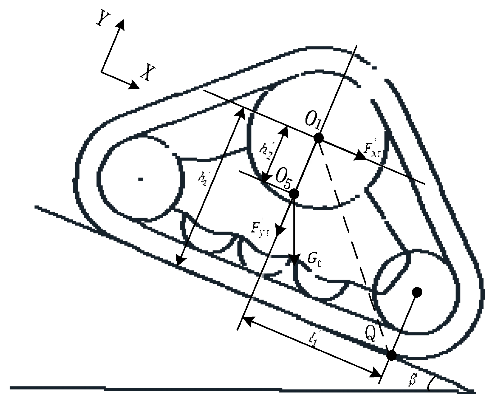
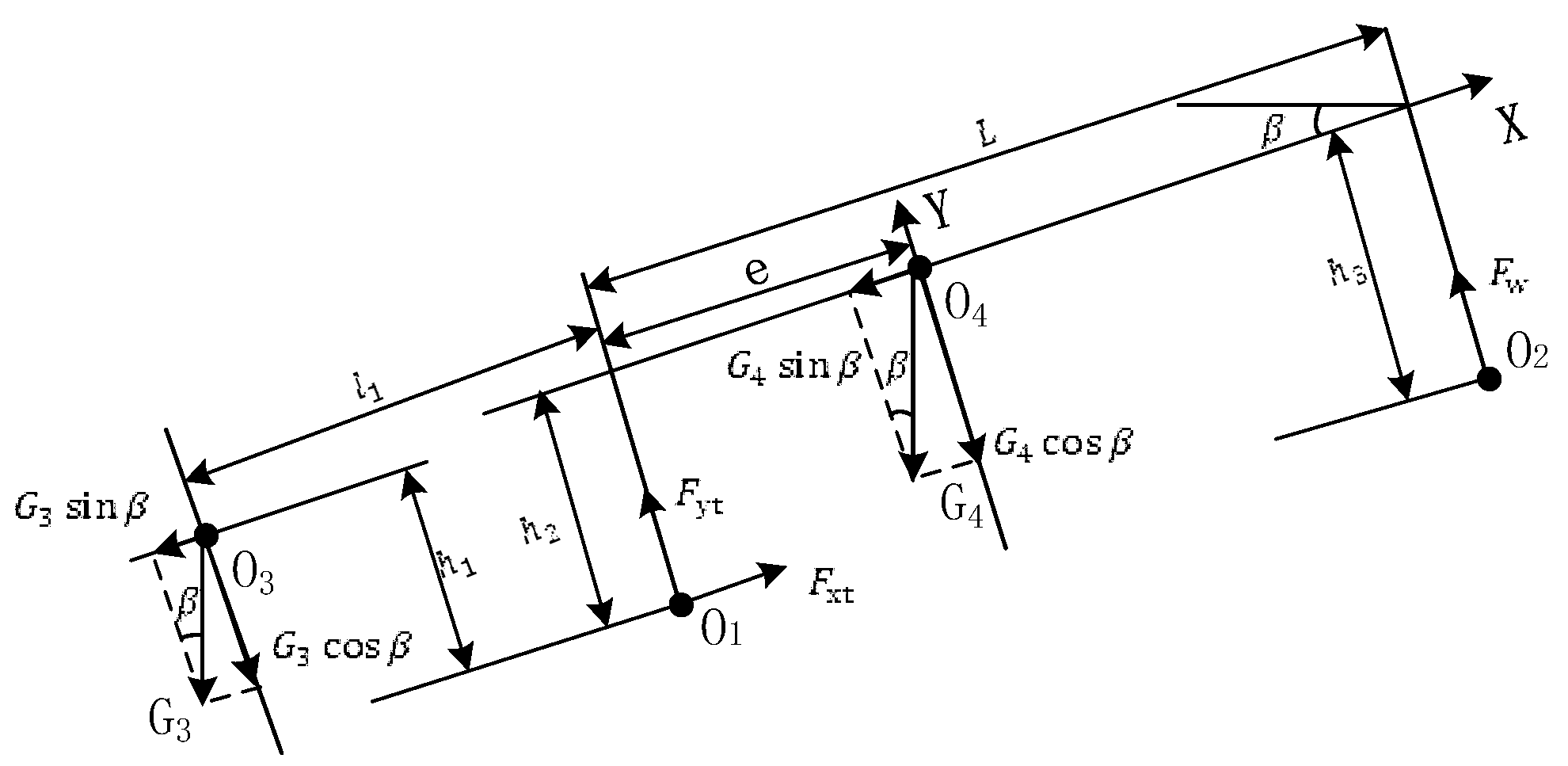
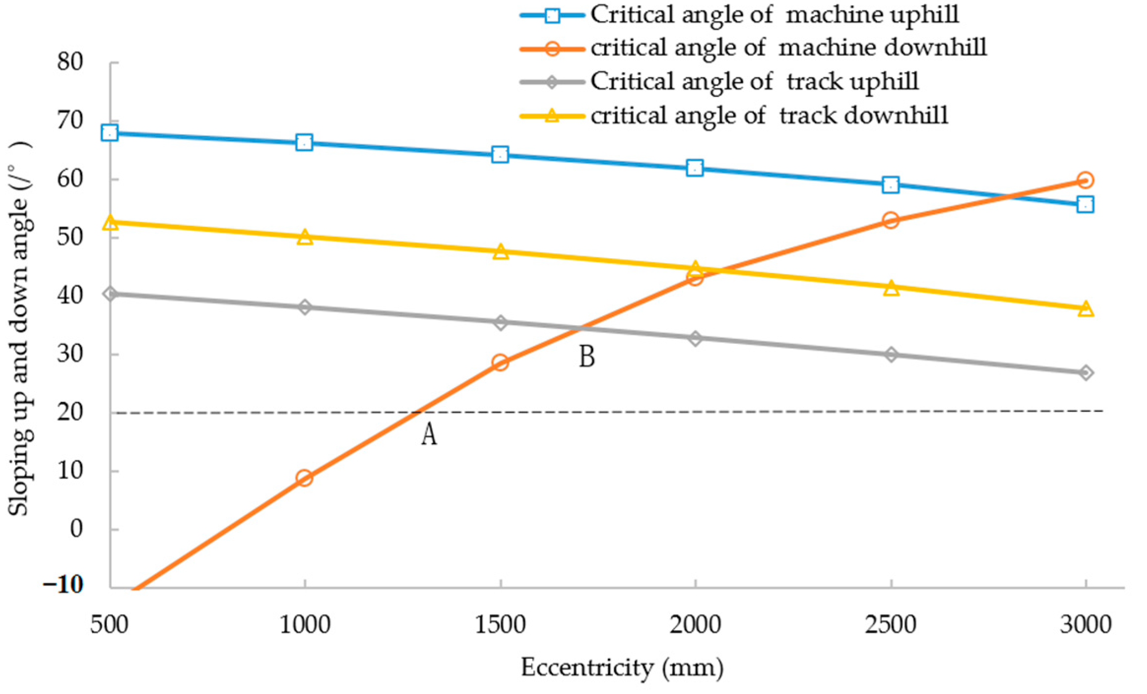
2.3. Performance Analysis of Uphill and Downhill

The longitudinal stability is an important indicator of the high clearance machine, and it also reflects the uphill and downhill performance of the machine. For climbing performance, in addition to considering the traction performance of the machine, safety is more important. It should meet the following two points, i.e., that the machine can go up or down the slope safely. Firstly, the whole machine does not flip, and the contact force between the front track and the ground should be greater than 0 when it is uphill, and the contact force between the rear wheel and the ground should be greater than 0 when it is downhill. Secondly, the triangular track does not turn 360° around driving shaft. Because the front track is only connected with the frame through the central axis O 1 of the driving wheel, the triangular track can rotate 360° around O 1 . In order to ensure that the track does not flip entirely, it is necessary to ensure that the intersection of the extension line of force sustained by the track at O 1 and the slope should be in the contact surface of the track and slope [22].
When the machine goes up or down the slope, the header would rise to the highest position, and the gravity center of the header rises too. The stress diagram is shown in Figure 4.

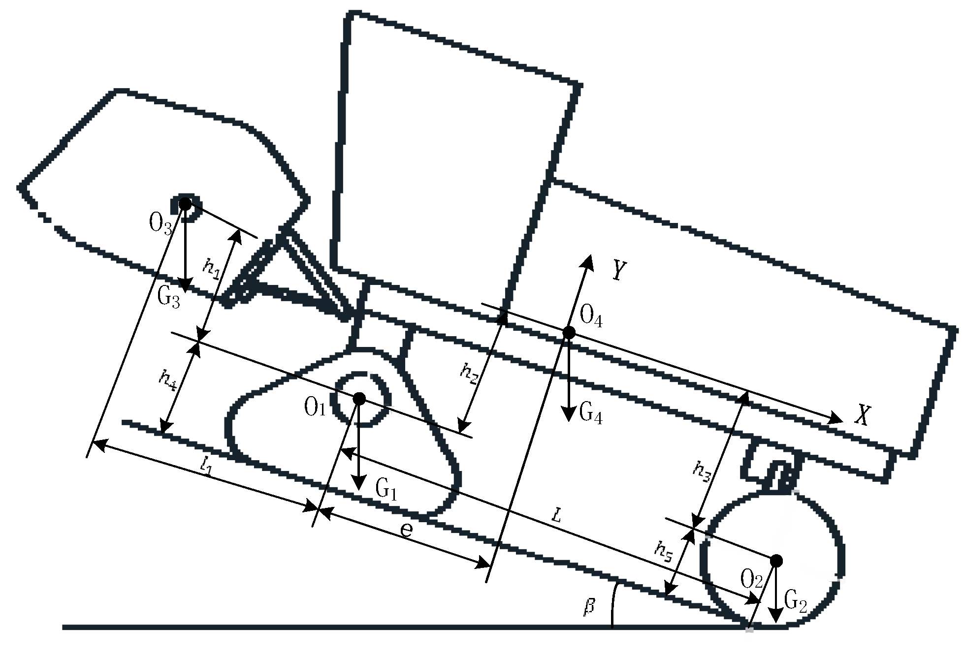
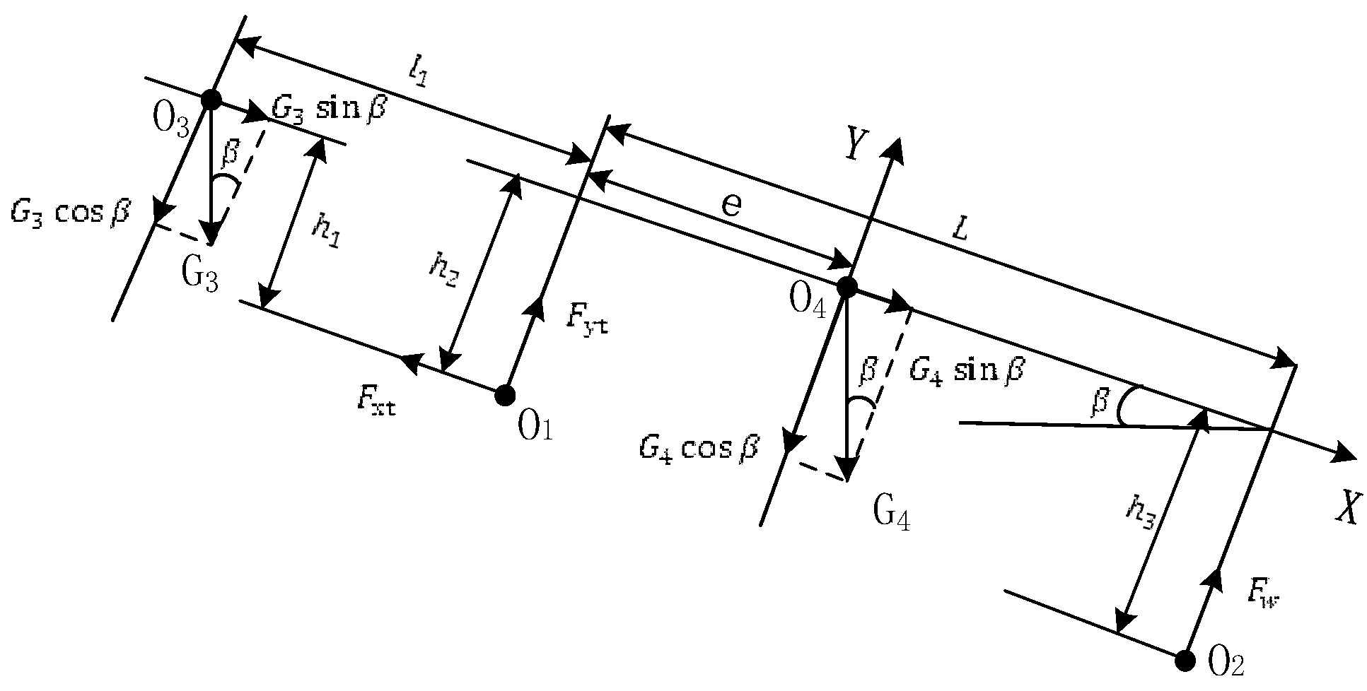
2.3.1. The Whole Machine Stability Analysis of Uphill and Downhill

When the machine is in the critical condition of uphill, the force between the front track and ground is 0. The tire is regarded as a rigid body, and the moment-equilibrium equation is:
G 3 sin β h 1 + h 4 + G 1 sin β h 4 + G 4 sin β h 2 + h 4 + G 2 sin β h 5 = G 3 cos β l 1 + L + G 1 cos β L + G 4 cos β L e
So:
tan β = G 3 l 1 + L + G 1 L + G 4 L e G 3 h 1 + h 4 + G 1 h 4 + G 4 h 2 + h 4 + G 2 h 5
where G 1 ,   G 2 are weights of track and wheel, 8800 N and 1200 N,   l 1 is distance along X axis between gravity center of header and the force bearing point of track, 1957 mm;   L is wheelbase, 2950 mm; h 1 is the distance along Y axis between gravity center of header and triangle track rotation center of 808 mm (header is in lifting position); h 2 is the distance along Y axis between gravity center of chassis frame and triangle track rotation center, 873 mm; h 4 is the distance along Y axis between triangle track rotation center and ground. h 5 is the distance along Y axis between the tire center and the ground, 497.5 mm.
Putting the known values in Equation (21), the maximum angle of the slope that the machine can climb is:
β u p = tan 1 13403 2 e 5050.34
The calculation of downhill critical angle is similar to that of uphill. If the whole machine is unstable when going downhill, the chassis frame and header would flip around the drive shaft of the track. When the contact force between the rear wheel and ground is 0, the torque balance equation of the critical state is:
G 3 sin β h 1 + G 3 cos β l 1 + G 4 sin β h 2 + G 2 sin β h 4 h 5 = G 4 cos β e + G 2 cos β L
We can get:
tan β = G 4 e + G 2 L G 3 l 1 G 3 h 1 + G 4 h 2 + G 2 h 4 h 5
The known parameters are substituted into Equation (24):
β d = tan 1 2 e 1603 2569.66

2.3.2. The Track Stability Analysis of Uphill and Downhill

The contact area and contact force between the track and ground change a lot when the machine is on the slope compared with that on the flat ground. In order to ensure that the track does not flip, the force at point O 1 needs to be determined first. From the above analysis, it can be seen that the rear wheel is a slave wheel without driving force, and the walking resistance is much smaller than that of the track. The ground support reaction force of the wheel is much larger than the frictional resistance, so the support reaction force of the wheel on the frame is simplified to the force perpendicular to the slope. The stress analysis of the frame is shown in Figure 5.
The moment balance equations are as below:
G 3 sin β + G 4 sin β F x t = 0 F y t + F w G 3 cos β G 4 cos β = 0 G 3 sin β h 1 + G 4 sin β h 2 + G 4 cos β e G 3 cos β l 1 F w L = 0
where F x t ,   F yt are forces of track on frame in X and Y direction, N. F w is the force of rear wheel on frame, N; h 3 is the distance along Y axis between force bearing point of the wheel and the centroid of chassis, mm.
After calculation, F x t and F y t can be expressed as below:
F x t = G 3 sin β + G 4 sin β
F y t = G 3 cos β L l 1 + G 4 cos β L e G 3 sin β h 1 G 4 sin β h 2 L
The force sustained by the track from the chassis frame and its own gravity is shown in Figure 6. The triangular track is subjected to the ground force, the frame reaction force F x t ,   F y t and its own gravity G t . The track is arranged symmetrically on the left and right sides, and the distance from the center of the driving axle to the center of its gravity point O 5 is h 2 . When the triangular track reaches the critical flipping position, it contacts the ground only at point Q. Therefore, the requirement that the triangular track does not flip itself is:
F y t + G t cos β l 1 > F x t h 1 + G t sin β h 1 h 2
where F x t   and   F y t have equal values but opposite directions with F x t and F y t , l 1 is the distance from the track driving center to the only contact point of track and ground along X axis, 550 mm; h 1 is the distance from track driving center to the ground along Y axis, 633 mm; h 2 is the distance from track driving center to the gravity center along Y axis, 238 mm.
According to Equations (27)–(29), an inequality can be derived as below:
tan β < G 3 L l 1 + G 4 L l 1 + G 3 l 1 l 1 + G t L l 1 G 4 l 1 e G 3 h 1 l 1 + G 4 h 2 l 1 + G 3 + G 4 L h 1 + G t L h 1 h 2
The known parameters are substituted into the above equation:
tan β < 13403 2 e 14604
When the machine is uphill, the maximum angle that the triangle track can work normally is as below:
β s u p = tan 1 13403 2 e 14604
The analysis method of downhill is similar to that of uphill. The force schematics of the rape windrower going downhill are shown in Figure 7, and the equation is established as follows:
G 3 sin β + G 4 sin β F x t = 0 F y t + F w G 3 cos β G 4 cos β = 0 G 3 sin β h 1 + G 3 cos β l 1 + G 4 sin β h 2 G 4 cos β e + F w L = 0
Results obtained by calculation as follows:
F x t = G 3 sin β + G 4 sin β
F y t = G 3 cos β L + l 1 + G 4 cos β L e + G 3 sin β h 1 + G 4 sin β h 2 L
The requirement that triangle track does not flip 360° when it is downhill is the same as uphill:
F y t + G t cos β l 1 > F x t h 1 + G t sin β h 1 h 2
So, the critical angle is:
tan β < G 3 L + l 1 l 1 + G 4 L e l 1 + G t l 1 L G 3 L h 1 + G 4 L h 1 + G L h 1 h 2 G 3 h 1 l 1 G 4 h 2 l 1
The known parameters are substituted by values, then Equation (37) can be simplified to the following:
tan β < 13403 2 e 9496
When the machine is downhill, the maximum angle where the triangle track does not flip 360° is:
β s d = tan 1 13403 2 e 9496
From Equations (22), (25), (32) and (39), the relationship between the critical angle of the uphill and downhill slope of the machine and the eccentricity of the chassis is shown in Figure 8. The critical angle of uphill and downhill decreases with the increase of chassis frame eccentricity; the critical angle of the triangular track downhill decreases and that of uphill increases. In Figure 8, the vertical coordinate of point A is 20°, which is the minimum angle of uphill and downhill that the machine should satisfy, and the corresponding horizontal coordinate is 1269 mm, which is the minimum eccentricity for the chassis. With the increase of eccentricity, the limit angle of uphill and downhill of the whole machine gradually increases, and the angle of uphill gradually decreases after reaching point B. The eccentricity of the horizontal coordinate corresponding to point B is 1684.3 mm, and the vertical coordinate is 34.5°, which is the maximum angle uphill and downhill of the whole machine.

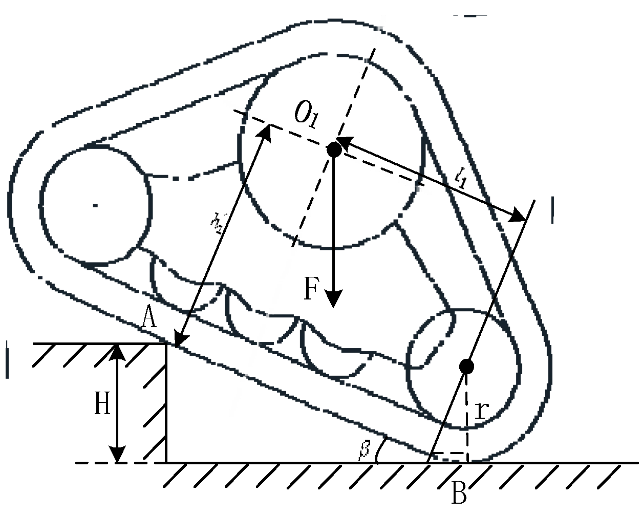
2.4. Performance Analysis of Ridge Crossing

There are great differences between a wheel-track chassis, a four-wheel chassis and a double-track chassis. The schematic of a triangle track crossing ridge is shown in Figure 9. It mainly experiences the following four stages when crossing the ridge [23].
In the first stage, the track contacts the steps, and the triangular track rotates clockwise around the center of the rotation axis; the whole machine also rotates clockwise besides moving forward. If one track and one tire are selected as the research objects, in this process, the contact between the machine and ground changes from one point (contact point between wheel and ground) and one face (face and face contact between the track and ground) to two lines and one point, namely lines A and B in Figure 9 and the contact point between wheel and ground.
The second stage is the obstacle crossing process where the machinery continues to move forward. The rotation angle of the triangular track increases until the counterclockwise torque is generated around O 1 by the force exerted on the triangular track at point A, then the contact force at point B gradually decreases to 0. In this process, the relationship between the machine and ground changes from a three-point contact to two-point contact.
The third stage is the completion stage of track obstacle crossing. In this process, the track gradually ascends and rotates counterclockwise around point O 1 until it fully contacts the ridge. The relationship between machine and ground changes from two-point contact to point-surface contact.
The fourth stage is the completion stage of the whole machine obstacle crossing. As the machine continues to move forward, the wheels make contact with the ridge and cross to complete the whole process of an over-obstacle.
It is necessary to ensure that the triangular track does not flip itself when the machine crosses the ridge completely, and the height of the obstacle is less than the radius of the rear wheel. Therefore, the following conditions should be satisfied between the ridge height and the triangular track parameters:
H = ( l 1 h 2 tan β ) sin β + r r cos β H < h 5
In the formula, H is the height of an obstacle that the machine can cross, mm; r is the distance from the center of guiding wheel to ground, 245 mm; β is the angle between the track and ground.
According to Equation (32), we can see the angle range at which the track does not flip 360° when uphill. According to Equation (40), the maximum height of the obstacle can be obtained. It is also known that the maximum height of the obstacle which the machine can cross is related to the mechanism parameters and eccentricity of the chassis. When the chassis structure parameters are determined, the relationship between the maximum obstacle height and eccentricity is as follows:
tan β = 13403 2 e 14604 H m a x = 550 238 tan β tan 2 β 1 + tan 2 β + 245 1 1 1 + tan 2 β
When the eccentricity increases, the critical angle of flipping 360° of the triangle track decreases, and the obstacle height decreases.

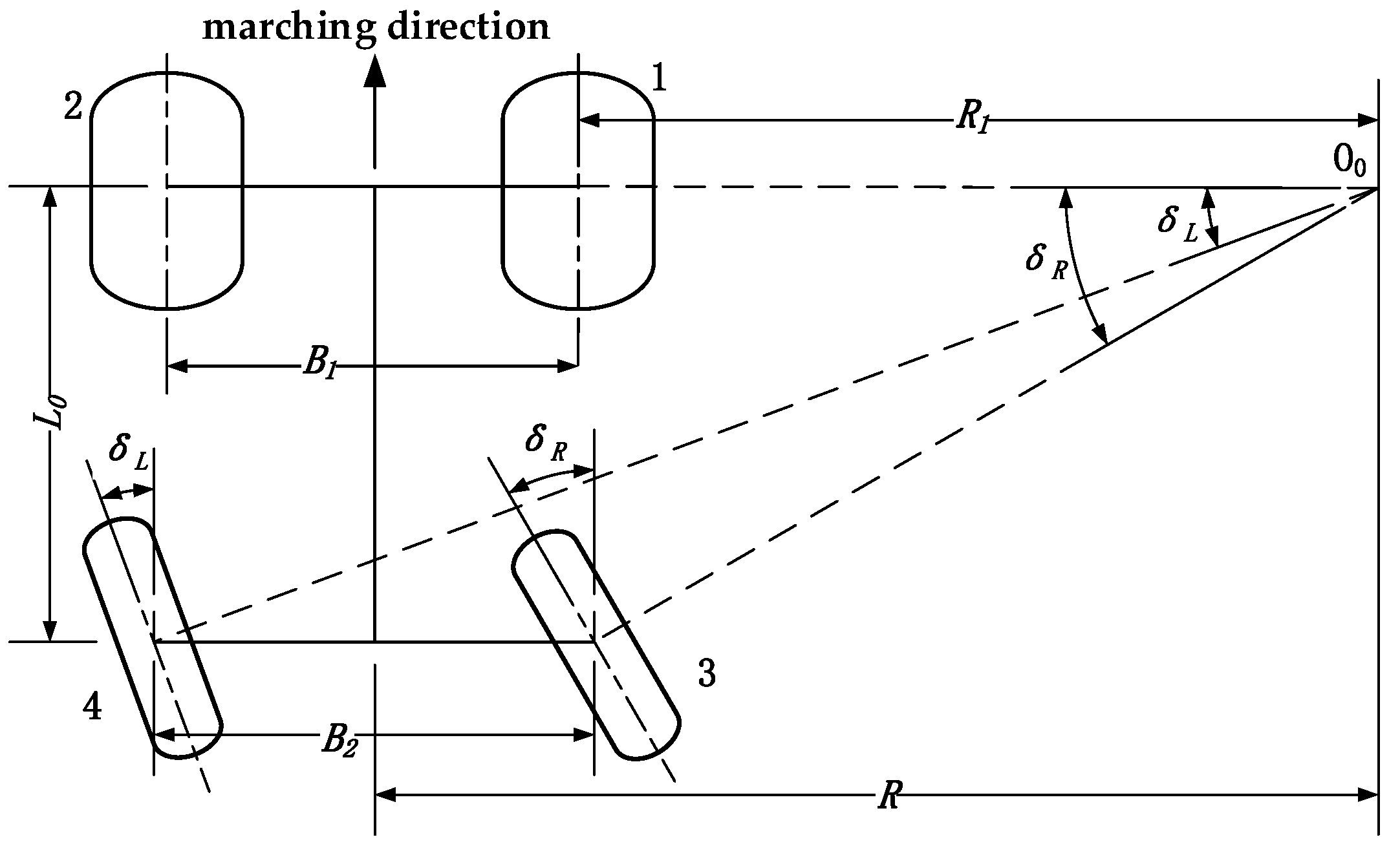
2.5. Analysis of Turning Performance

When the machine turns, it should avoid additional resistance with the ground and require the wheel (track) to roll purely without sliding, so the turning movement process conforms to Ackermann steering geometry and the axes of all wheels intersect at the center of rotation [24]. When the machine turns, rear wheels are active steering, one of them is deflected by index cylinder, and the other one is deflected by four-bar linkage, while the front tracks steer by differential. Taking the right turning as an example, the turning plane is shown in Figure 10.
According to the geometric relationship:
L = R B 1 2 tan δ R L = R + B 2 2 tan δ L
where R is turn radius, distance from turning center point to chassis center line, m; B 1 is the distance of two tracks, m; B 2 is the distance of two rear wheels, m; δ L is the left back steer angle, rad; δ R is the right back steer angle, rad.
In order to satisfy the above equations, the turn angles δ L and δ R of the outer and inner wheels should meet the following requirements:
δ R = cot 1 cot δ L B 2 L
When steering, any point of the machine rotates around point O 0 , and if the windrower steering angular velocity is named ω , the speed of the two tracks and two wheels are as follows:
v 1 = ω R B 1 2 v 2 = ω R + B 1 2 v 3 = ω R B 2 2 cos δ R v 4 = ω R + B 2 2 cos δ L
where v 1 , v 2 , v 3 , v 4 are speeds of wheels and tracks, B 1 is the distance of two tracks.
Therefore, the speed relationship of the left and right tracks is:
v 1 v 2 = R 1 R 1 + B 1
The geometric relationship in Figure 10 shows:
R 1 = L cot δ R + B 2 B 1 2
Put Equation (46) into Equation (45), and the speed ratio of two tracks can be obtained as:
v 1 v 2 = 2 L cot δ R + B 2 B 1 2 L cot δ R + B 2 + B 1
The theoretical turn radius is:
R = L cot δ R + B 2 2
Equation (48) shows that the theoretical turn radius is related to the steering angle and the center distance between two rear wheels. The larger the turn angle is, the smaller the turning radius becomes. Putting known values L = 2950   mm , δ R = 35 ° , B 2 = 2646   mm into Equation (48), the minimum turn radius 5537.28 mm can be gained.

2.6. Kinematics Simulation and Analysis

2.6.1. Creation of Simulation Model

A three-dimensional solid model is created based on Pro/E software, and the model is exported in Parasolid (*.x-t) format. Then, the model is imported into software RecurDyn, maintaining the assembly relationship and simplifying the solid model [25,26,27,28,29]. As the model is simplified, the weight of the machine is quite different from the actual weight, so it is reset according to the actual weight of the machine [30].
The front triangle track is built in Track (LM) module of RecurDyn, the wheel model is built in Tire module, and the constraints and traction between components are built [31,32]. The track system is connected with the frame by rotating join. The track drives the movement of each link through the rotation of the driving wheel to pull the machine forward. The modeling is shown in Figure 11. The driving function of two tracks is: step (time, 0, 0, 1.5, −3.32), which means that the speed of the driving wheel increases from 0 to 3.32 rad/s in the period of 0~1.5 s.

2.6.2. Simulation Analysis of Walking on Flat Ground

Clay soil model is selected as track contact soil. With the increase of eccentricity, the ability of crossing ridge is reduced. Therefore, the eccentricity is set based on the points A and B in Figure 8. Simulations are operated at 100 mm increments from 1184 mm to 1784 mm. A single factor simulation test is carried out with test indexes of walking speed and driving torque. The simulation time is set as 15 s and the number of steps is set as 100. The simulation results of the walking speed and the driving torque of a single track when the chassis eccentricity is 1184 mm, 1484 mm and 1784 mm are shown in Figure 12 and Figure 13.
In Figure 12 and Figure 13, the blue curves are velocity–time curve and torque–time curve at eccentricity of 1184 mm, the green curves are velocity–time curve and torque–time curve at eccentricity of 1484 mm, and the red curves are velocity–time curve and torque–time curve at eccentricity of 1784 mm. It can be seen that with the increase of eccentricity, the smoother the velocity and torque become.
When the system is stable, the average speed and average driving torque of the simulation during 3~14 s are selected. The average speed is calculated as follows:
v ¯ = 1 n i = 1 n v i
where v ¯ is the average speed, mm/s; v i is instantaneous speed of each sampling point, mm/s; n is the number of sampling points.
The relationship between eccentricity and average speed and average driving torque is shown in Figure 14.
With the increase of eccentricity, the average speed of the machine changes very little. When the eccentricity is 1284 mm, the maximum speed is 1081.6 mm/s. The average driving torque decreases first and then increases slowly with the increase of eccentricity. When the eccentricity is 1484 mm, the minimum driving torque of a single track is 816.26 N∙m. Inserting this value of eccentricity into Equations (2) and (19), the theoretical driving resistance of the track is 5789 N. As the diameter of the driving wheel is 577 mm, the theoretical driving torque of a single track is 835.1 N·m. The internal friction of the machine is not considered in the simulation, so the value of simulation is smaller than that of the theoretical calculation, which verifies the correctness of the theoretical calculation.
Average speed and torque reflect the performance of the machine in a period of time. Regular vibration occurs when the track links make contact with the ground, so the instantaneous speed and torque have large differences, and coefficient variation (CV) can be used to judge the instantaneous stability which is calculated in Formulas (50) and (51).
S = 1 n 1 i = 1 n v i v ¯ 2
where S is speed standard deviation.
C V = S v ¯ × 100 %
where C V is coefficient variation of speed.
The calculation method of torque coefficient variation is the same as that of the speed coefficient variation.
The relationship between the coefficient variation of speed and torque and eccentricity is shown in Figure 15. The coefficient variation of speed decreases with the increase of eccentricity, and the stability becomes better and better. When the eccentricity is less than 1384 mm, the coefficient variation of speed varies significantly with the eccentricity. When the eccentricity is over 1384 mm, the change is slow and tends to be stable. The coefficient variation of driving torque decreases first and then increases with the increase of eccentricity. When the eccentricity is 1584 mm, the smallest coefficient variation is obtained, so the stability is the best.
The mechanical analysis shows that the eccentricity has a great influence on the driving resistance, stability, climbing performance and obstacle crossing ability of the machine. The simulation analysis of the machine walking in sticky soil shows that the eccentricity has little influence on the average walking speed, but has great influence on the speed stability, average driving torque and driving torque stability. When the values of eccentricity are 1484 mm and 1584 mm, the value of minimum driving torque is 816.26 N∙m and its coefficient variation is 140.99%.
According to the analysis of Section 2.3.2, when the uphill and downhill angle of the machine meets the design requirement of 20°, the eccentricity should be greater than 1269 mm. The maximum uphill and downhill angle can be obtained when the eccentricity is 1684.3 mm. In summary, taking driving torque as the main reference, and considering other indicators, the eccentricity is selected as 1500 mm. Therefore, the working parts can be arranged according to this eccentricity.

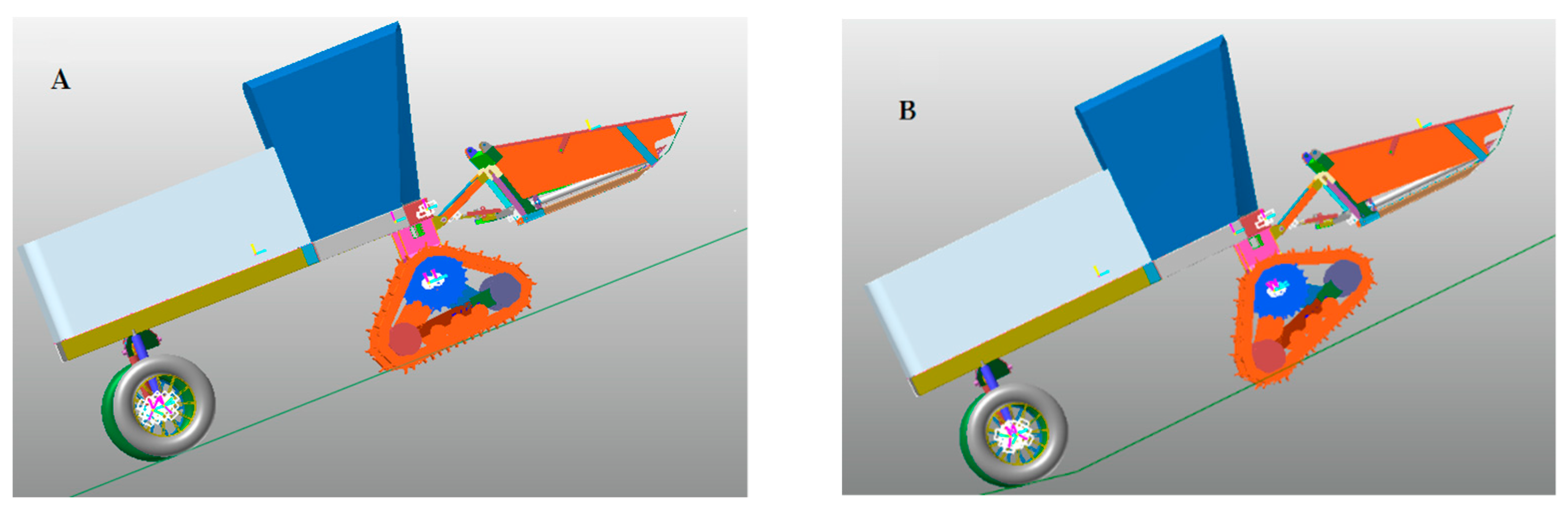
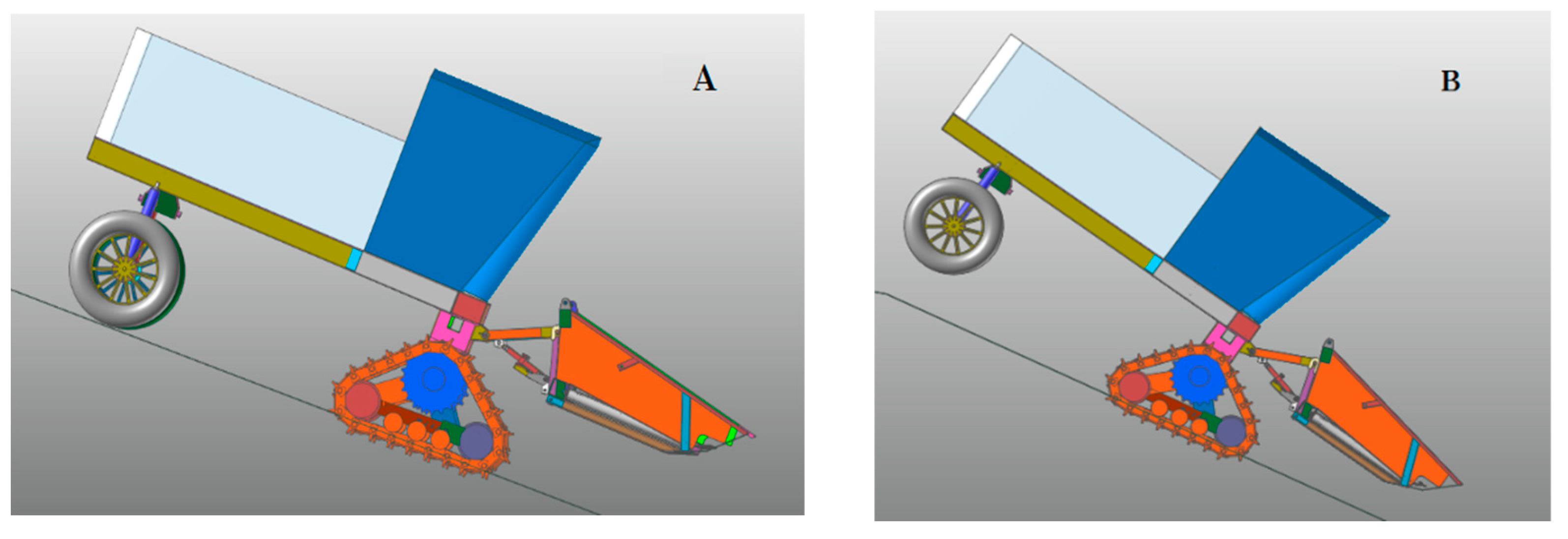
2.6.3. Simulation of Uphill and Downhill

The simulation of uphill and downhill is carried out with the eccentricity of 1500 mm, as in Figure 16 and Figure 17. The normal uphill and downhill states are shown in Figure 16A and Figure 17A. The instability state of uphill and downhill is shown in Figure 16B and Figure 17B. When the machine is uphill, the triangle track is unstable first, and the track flips around the driving axle. When the machine is downhill, the chassis frame flips around the driving axle first, which is consistent with the theoretical calculation results and verifies the correctness of the theoretical calculation.
The simulation shows that the maximum climbing angle of the machine is 28°, which is about 8.5° smaller than the theoretical calculation value. When the track is uphill, the combined force direction of the track deviates greatly from the track center line, which leads to the uneven distribution of the pressure between the track and the ground. The pressure on the latter part of the track is significantly higher than that on the front part. Therefore, the subsidence depth is not uniform, as shown in Figure 16B. The flipping of the track is not only affected by the slope angle, but also by the different subsidence depths of the track; at the same time, the vibration in the movement process also affects the stability, so the simulation angle is smaller than the theoretical calculation value.
The maximum downhill angle of the simulation is 26°, which is about 2.5° smaller than the theoretical calculation value. It can be seen from Figure 17B that even if the whole machine flips, the subsidence depth of the whole track does not change much, so the triangle track is relatively stable. The deviation between the simulation value and theoretical value is mainly affected by vibration factors in movement.

3. Test Results and Discussion

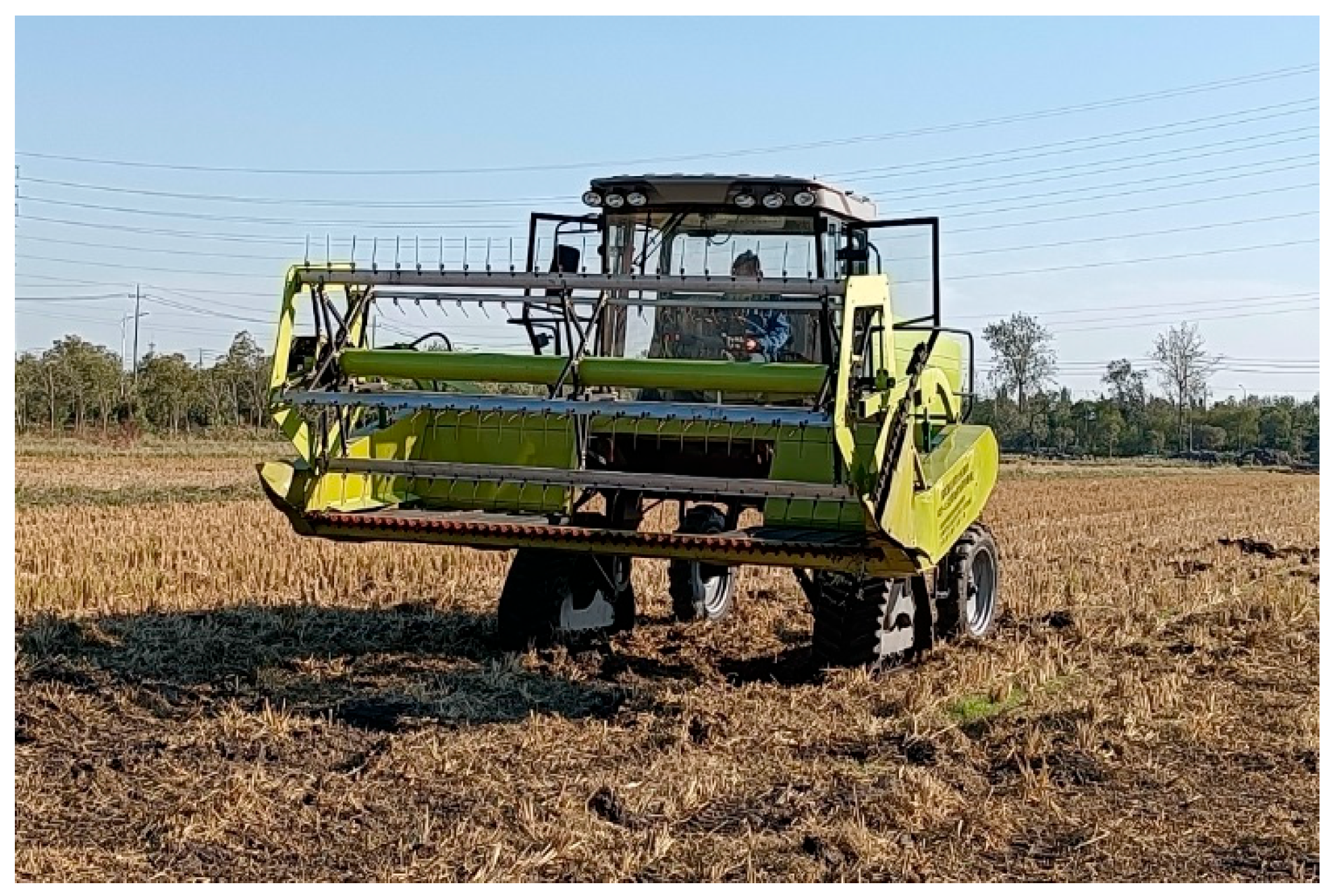
3.1. Walking Performance

In order to test the walking performance of the wheel-track high clearance chassis of this rape windrower, experiments were carried out on hard flat road and rice stubble field, as shown in Figure 18 and Figure 19. The rice stubble field was located in Comprehensive Demonstration Base of Rice and Wheat Science and Technology in Taizhou, Jiangsu, China. It was a rice stubble field after full straw returning. Soil physical parameters were as follows: moisture content was 38.7%, average soil hardness at 15 cm depth was 1233.4 kPa, average soil hardness at 30 cm depth was 1654.8 kPa, and the stubble height of rice was less than 10 cm.
First, the driver increased the speed to the top value of the corresponding gear position in the preparatory area. Then, the machine passed through the 20 m test area at a uniform speed, and the passing time was recorded. This process was repeated three times. The three 20 m passing times on hard flat ground of walking gear were 3.61 s, 3.48 s and 3.59 s; the average speed was 20.22 km/h. The three 20 m passing times of working gear on rice stubble field were 7.71 s, 7.56 s and 8.40 s and the average speed was 9.12 km/h, which satisfied the design index.

3.2. Climbing Test

The climbing performance test was carried out on the ground shown in Figure 20. Two steel plate tracks with a length of 6 m and a width of 0.8 m and four supporting legs were used to build the ramp. The large slope angle adjustment was realized by changing the supporting legs at different heights. The slope fine-tuning was implemented by changing the installation position of legs. In order to avoid danger, a limit block was installed on the side of the triangular track to prevent security accidents caused by automatic flipping of the track during climbing.
In the experiment, the machine could climb up the 20° slope with a slow speed, and the design performance of the machine was satisfied.

3.3. Turning Radius Test

Turning tests were conducted on the flat hard road and rice stubble field respectively. According to the minimum turning radius measurement method of GB/T3871.5-93 Test methods for agricultural wheeled and tracklaying tractors, the machine was driven at a low and uniform speed; at the same time, the steering wheel was respectively turned to the left or right limit positions. The machine drove out of the experiment block after it finished a whole circle path. Then, the turning radius of the inner track of the machine was measured. The experiments on two fields were both conducted three times; the results are shown in Table 2.
The minimum turning radius of the machine was R m i n = R a + 0.5 B 1 , where R a is the radius of inner track, mm; B 1 is the track gauge, 2090 mm.
Therefore, the minimum turning radius of the machine on flat hard road was 5.965 m, and the minimum turning radius on rice stubble field was 6.498 m.
In the theoretical calculation, it is assumed that the four wheels (tracks) are pure rolling without transverse or longitudinal slip. However, in fact, when the machine turns, the direction is controlled by the rear wheel, the front tracks were in a passive differential steering motion, and the slip phenomenon is inevitable. Therefore, the experimental radius is greater than the theoretical one. When the ground condition becomes worse, the resistance becomes larger, thus the effect of differential steering is poor, and a larger turning radius is acquired when running on rice stubble field than on flat hard ground.

4. Conclusions

(1)
The mechanism and working principle of the wheel-track high clearance chassis of rape windrower were introduced, and the models of mathematical relations between the walking performance, stability performance and the eccentricity of the chassis frame were built.
(2)
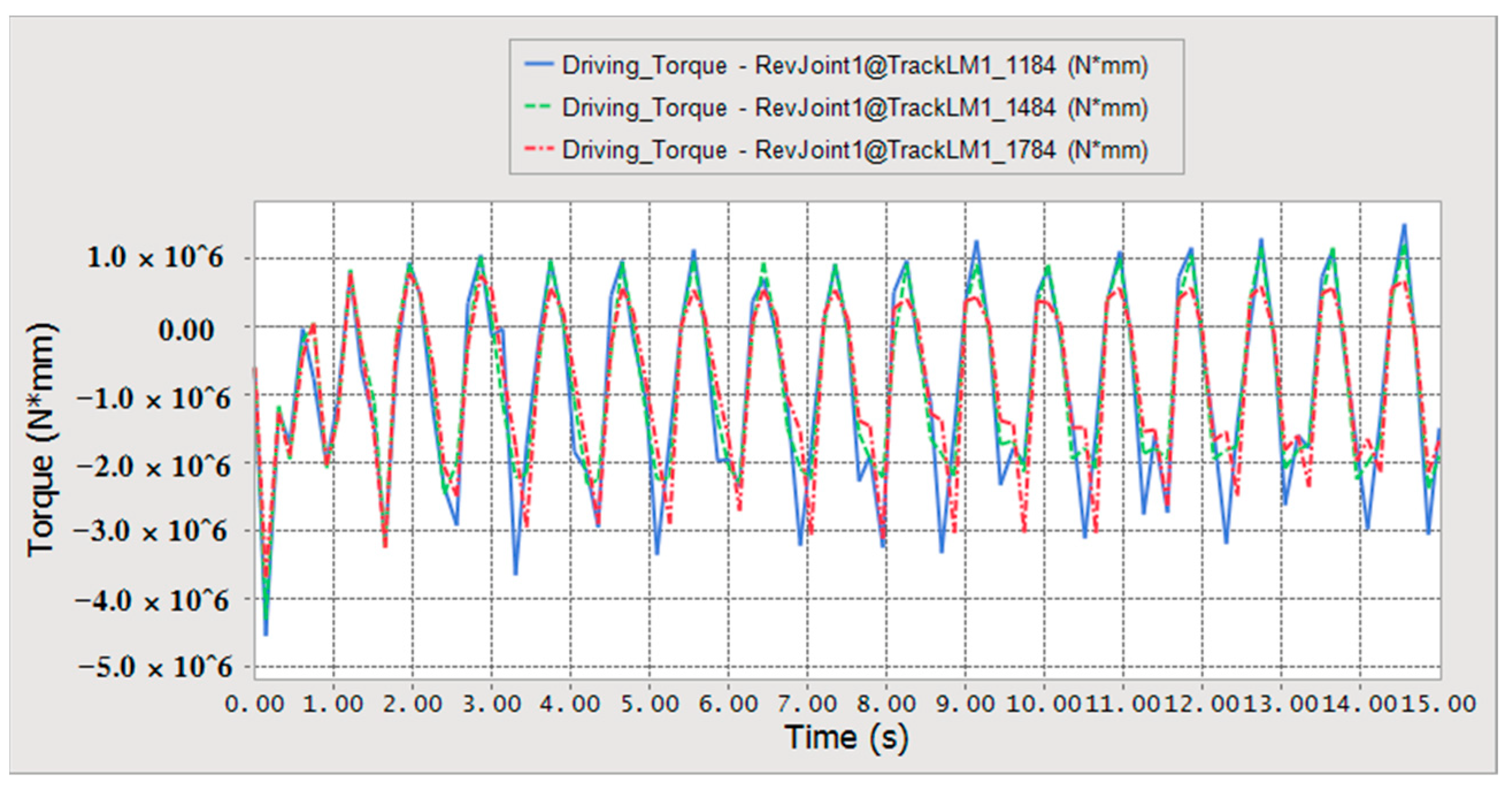
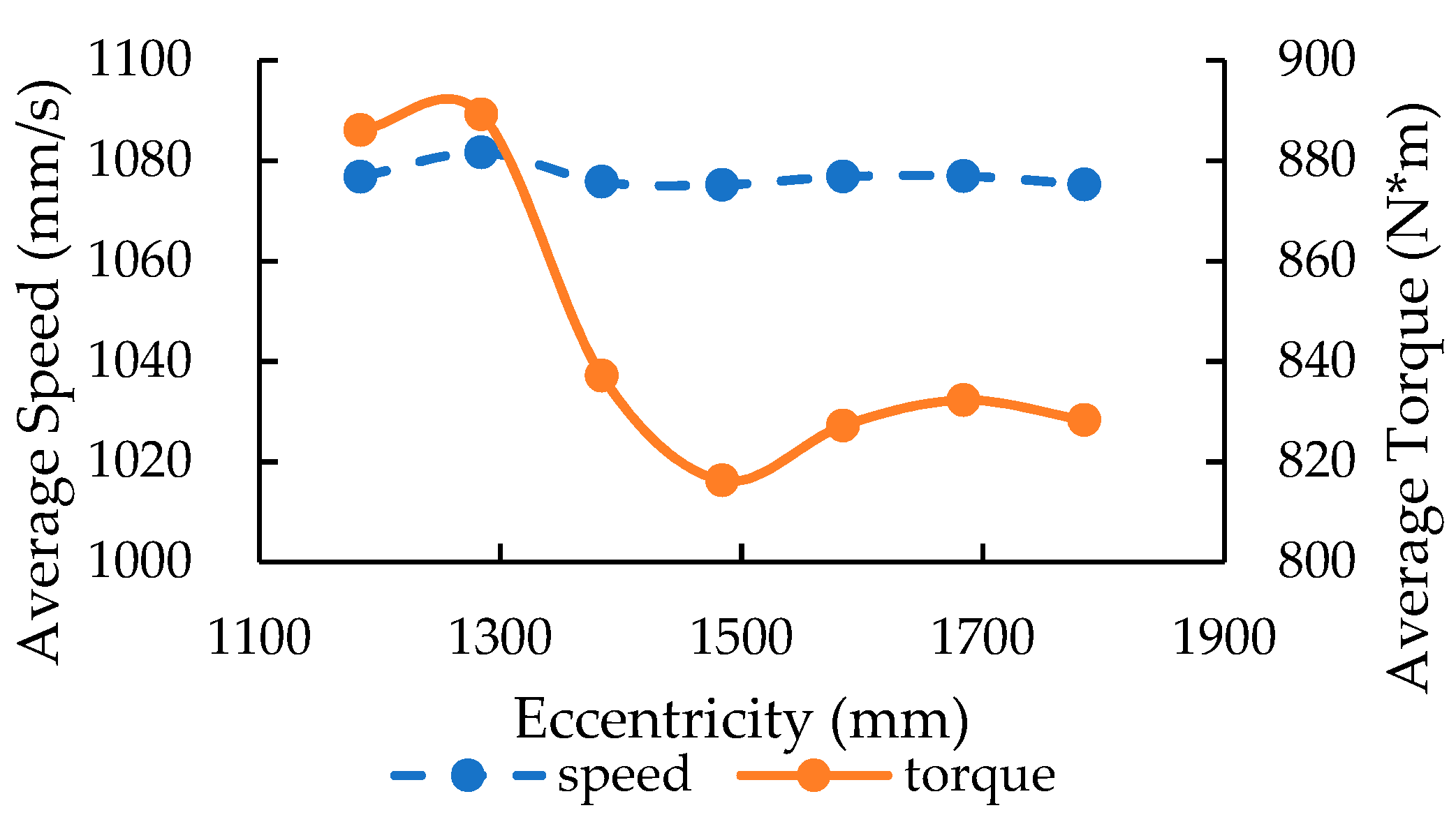
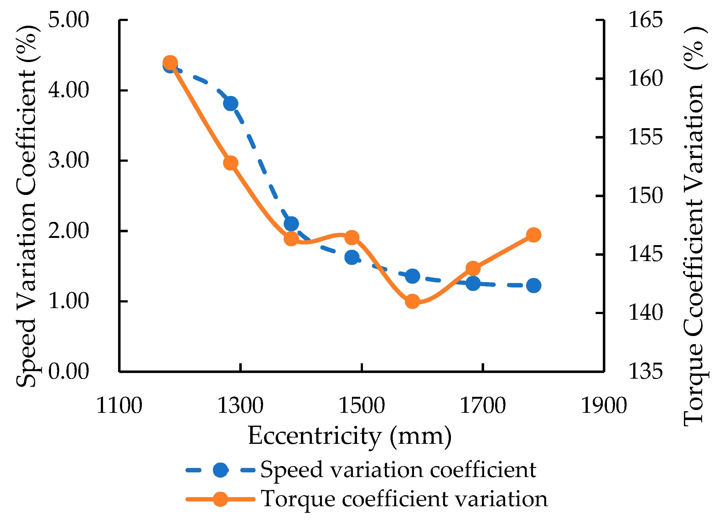
Three-dimensional model and dynamic simulations of a wheel-track high clearance rape windrower were conducted using Pro/E and RecurDyn software. When the machine was driven at the same speed, the walking speed changed little with the increase of eccentricity, and the coefficient variation of speed decreased gradually. The average driving torque and the coefficient variation decreased first and then increased. Minimum driving torque and the coefficient variation were obtained when the eccentricities were 1484 mm and 1584 mm. The chassis frame eccentricity was defined as 1500 mm, according to the theoretical calculation and simulation analysis. The maximum angle of uphill and downhill was 28° and the maximum height of the crossing ridge was 266.15 mm.
(3)
The performance experiments of wheel-track high clearance rape windrower in flat hard ground and rice stubble field were carried out. The test showed that the speed running on flat hard road was 0~20.22 km/h and the minimum turning radius was 5.965 m; the working speed in rice stubble field was 0~9.12 km/h and the minimum turning radius was 6.498 m. The machine could steadily climb the slope of 20°.
(4)
A new kind of wheel-track high clearance chassis was developed, which could hang on the swath header over than 3.5 m wide. All parameters of the chassis met the design requirements, and the work efficiency increased over 100% compared with the existing two-tracked rape windrower. This provided another kind of equipment for rapeseed harvesting in the Yangtze River Basin.

Author Contributions

Conceptualization, M.J. and M.Z.; methodology, C.W. and R.H.; software, G.W.; validation, S.L.; formal analysis, M.J.; investigation, M.J., M.Z. and S.L.; resources, C.W.; data curation, M.J.; writing—original draft preparation, M.J.; writing—review and editing, M.J.; visualization, R.H.; supervision, R.H.; project administration, M.Z.; funding acquisition, S.L. All authors have read and agreed to the published version of the manuscript.

Funding

This research was funded by Key Research Program & Technology Innovation Program of Chinese Academy of Agricultural Sciences (CAAS-ZDRW202105), and China Agriculture Research System of MOF and MARA (CARS-12).

Data Availability Statement

Data are available.

Acknowledgments

The authors thank the editor and anonymous reviewers for providing helpful suggestions for improving the quality of this manuscript.

Conflicts of Interest

The authors declare no conflict of interest.

References

  1. Shi, Z.; Wu, M.; Yang, W. Research status and development measures of rape segment harvester in China. Agric. Eng. 2015, 5, 1–4. [Google Scholar]
  2. Li, P. Experimental Study and Working Mechanism of Key Parts for Rape Windrower for 4SY 1.8. Ph.D. Thesis, Huazhong agricultural university, Wuhan, China, 2014. [Google Scholar]
  3. Jin, C.; Yang, T.; Liu, G. Design and Test of Posture Controlled Chassis for Caterpillar Combine. Trans. Chin. Soc. Agric. Mach. 2020, 51, 393–402. [Google Scholar]
  4. Hu, K.; Zhang, W.; Li, K. Multi-body dynamics modeling and experiment of triangular tracked chassis with high ground clearance. Trans. Chin. Soc. Agric. Mach. 2021, 52, 386–394. [Google Scholar]
  5. Zhou, J.; Cheng, X.; Li, H. Research and development on the wheel electric rape harvester. J. Agric. Mech. Res. 2012, 34, 80–85. [Google Scholar]
  6. Zhu, Y.; Fei, Y.; Xu, H. Analysis for obstacle negotiation of a wheel-track-leg hybrid mobile robot machine design and research. Mach. Des. Res. 2017, 33, 28–32. [Google Scholar]
  7. Shuai, L.; Su, H.; Zhen, L. Study on steering movement of track-wheel mobile robot. J. Harbin Eng. Univ. 2017, 38, 1630–1634. [Google Scholar]
  8. Zhang, S.; Yao, J.; Xu, Y. Design and analysis of moving mechanism of shape reconfigurable mobile robot. Trans. Chin. Soc. Agric. Mach. 2019, 50, 418–426. [Google Scholar]
  9. Guo, T. Power consumption of tracked and wheeled small mobile robots on deformable terrains–model and experimental validation. Mech. Mach. Theory 2019, 133, 347–364. [Google Scholar] [CrossRef]
  10. Jun, L.; Andrew, A.G. Development of a terrain adaptive tracked vehicle and its derivative-dual mode vehicle. In Proceedings of the 1st WRC Symposium on Advanced Robotics and Automation, Beijing, China, 16 August 2018. [Google Scholar]
  11. Zang, L.; Yang, S.; Wu, C. Design and kinematics analysis of coordinated variable wheel-track walking mechanism. Int. J. Adv. Robot. Syst. 2020, 17, 1–12. [Google Scholar] [CrossRef]
  12. Bai, Y. Design and Test on Delta Tracks Chassis of Chopper Sugarcane Harvester. Master’s Thesis, South China Agricultural University, Guangzhou, China, 2014. [Google Scholar]
  13. Cai, G. The Design and Mechanical Analysis of Oil Camellia Fruit Picking Machine’s Rubber Track System Chassis. Ph.D. Thesis, Central South University of Forestry and Technology, Changsha, China, 2014. [Google Scholar]
  14. Wang, F. Study on Slope Passability of the Orchard Power Chassis in Hilly Area. Master’s Thesis, Southwest University, Chongqing, China, 2020. [Google Scholar]
  15. Zeng, S.; Liu, J.; Luo, X. Design and experiment of wheel-track compound power chassis for high clearance sprayer in paddy field. J. South China Agric. Univ. 2019, 40, 14–22. [Google Scholar]
  16. Hao, Z.; Yang, X.; Liu, L. Design and experiment of multifunctional dynamic chassis for orchard. Trans. Chin. Soc. Agric. Mach. 2018, 49, 66–73+92. [Google Scholar]
  17. Pan, G.; Yang, F.; Sun, J. Analysis and test of obstacle negotiation performance of small hillside crawler tractor during climbing process. Trans. Chin. Soc. Agric. Mach. 2020, 51, 374–383. [Google Scholar]
  18. Feng, Y. Tank and Armored Vehicle Design; Chemical Industry Press: Beijing, China, 2015; pp. 31–72. [Google Scholar]
  19. Ge, J.; Zhang, D.; Wang, X.; Cao, C.; Fang, L.; Duan, L. Tractive performances of single grouser shoe affected by different soils with varied moisture contents. Adv. Mech. Eng. 2019, 11, 1–11. [Google Scholar] [CrossRef] [Green Version]
  20. Yao, H.; Chen, B. Engineering Machinery Chassis Theory; China Communications Press: Beijing, China, 2001; pp. 15–70. [Google Scholar]
  21. Deng, Z.; Ding, L.; Gao, H. Influence of soil properties on lunar rover’s wheel-oil interaction mechanics. J. Harbin Inst. Technol. 2010, 42, 1724–1729. [Google Scholar]
  22. Zhao, J.; Wang, F.; Yu, B. Research on All-terrain profiling crawler power chassis. Trans. Chin. Soc. Agric. Mach. 2014, 45, 20–24. [Google Scholar]
  23. Zhu, Y.; Sang, Y.; Hu, M. Design and tability analysis of sprayer with adjustable height gap. J. Agric. Mech. Res. 2020, 42, 68–73. [Google Scholar]
  24. Xu, C.; Chen, Y.; Li, R. Design and research on Highland gap self-propelled lance spray. J. Chin. Agric. Mech. 2016, 37, 51–54. [Google Scholar]
  25. Wang, H.; Wang, Q.; Rui, Q. Analyzing and testing verification the performance about high-speed tracked vehicles in steering process. J. Mech. Eng. 2014, 50, 162–172. [Google Scholar] [CrossRef]
  26. Jiao, X.; Zhang, J.; Peng, B. Recurdyn Multibody Systems Optimization Simulation Technology; Tsinghua University Press: Beijing, China, 2010; pp. 62–101. [Google Scholar]
  27. Liu, Y.; Zhang, T.; Xie, N. Multi-body dynamic modeling and verification of small agricultural crawler chassis. Trans. Chin. Soc. Agric. Eng. 2019, 3, 39–46. [Google Scholar]
  28. Chen, J.; Huang, R.; Mo, R. Analysis and simulation of obstacle crossing performance of tracked chassis of small hedge trimmer based on RecurDyn. J. Chin. Agric. Mech. 2020, 41, 89–98. [Google Scholar]
  29. Ma, P.; Liu, Y.; Shi, C. Dynamics analysis and simulation of variant wheel-track wheel based on RecurDyn. J. Mil. Transp. Univ. 2017, 19, 35–39. [Google Scholar]
  30. Jiang, Q.; Ni, W.; Zhang, X.; Chen, P.; Yang, Y. Evaluation of tractor driving comfort according to the steering angle and speed using a virtual prototype. Proc. Inst. Mech. Eng. Part D J. Automob. Eng. 2021, 235, 50–61. [Google Scholar] [CrossRef]
  31. Zhao, J.; Wang, W.; Sun, Z. Improvement and verification of pressure-sinkage model in homogeneous soil. Trans. Chin. Soc. Agric. Eng. 2016, 32, 60–66. [Google Scholar]
  32. Yao, Y. Research on the trafficability of low-seed tracked vehicle based on track-soil coupling system. Ph.D. Thesis, Jilin University, Changchun, China, 2016. [Google Scholar]
Figure 1. Structural diagram of a wheel-track high clearance rape windrower. (A) Main view; (B) Vertical view (removal of cab and frame top cover).
Agriculture 12 01150 g001
Figure 2. Force analysis of rape windrower on flat road.
Agriculture 12 01150 g002
Figure 3. Interaction between track guide wheel and soil.
Agriculture 12 01150 g003
Figure 4. Schematic of the rape windrower when climbing up.
Agriculture 12 01150 g004
Figure 5. Force schematic of the rape windrower when climbing up.
Agriculture 12 01150 g005
Figure 6. Partial force schematic of the triangular track when climbing up.
Agriculture 12 01150 g006
Figure 7. Force schematics of the rape windrower when driving down the slope.
Agriculture 12 01150 g007
Figure 8. The maximum angle uphill and downhill.
Agriculture 12 01150 g008
Figure 9. Schematic of triangular track crossing the ridge.
Agriculture 12 01150 g009
Figure 10. Diagram of turning.
Agriculture 12 01150 g010
Figure 11. Three-dimensional model of a rape windrower.
Agriculture 12 01150 g011
Figure 12. Walking speed with different eccentricities.
Agriculture 12 01150 g012
Figure 13. Driving torque with different eccentricities.
Agriculture 12 01150 g013
Figure 14. Relationship between speed, torque and eccentricity.
Agriculture 12 01150 g014
Figure 15. Relationship between speed variation coefficient, torque variation coefficient and eccentricity.
Agriculture 12 01150 g015
Figure 16. Uphill simulation. (A) Stable uphill state; (B) Unstable uphill state.
Agriculture 12 01150 g016
Figure 17. Downhill simulation. (A) Stable downhill state; (B) Unstable downhill state.
Agriculture 12 01150 g017
Figure 18. Running on the flat hard ground.
Agriculture 12 01150 g018
Figure 19. Running on rice stubble field.
Agriculture 12 01150 g019
Figure 20. Climbing test.
Agriculture 12 01150 g020
Table 1. Main technical parameters of the wheel-track high clearance chassis.
Parameters/UnitsNumerical Value (Manner)
Power/kW68
Driving modeTwo-track drive
Steering modeRear-wheel steering
Walking mechanismWheel-track combination
Minimum ground clearance/mm970
Front track gauge/mm2090
Rear wheel gauge/mm2646
Wheelbase2950
Uphill and downhill angle/°20
Walking speed/km/h≥20
Table 2. Turning radius of inner track.
Serial Number1/mm2/mm3/mmAverage Value/mm
Flat and hard roadLeft-turn4950488048904906.7
Right-turn4960490049004920
Rice stubble fieldLeft-turn5450544054405443.3
Right-turn5460545054505453.3
Publisher’s Note: MDPI stays neutral with regard to jurisdictional claims in published maps and institutional affiliations.

