Article

Development of Centrifugal Disc Spreader on Tracked Combine Harvester for Rape Undersowing Rice Based on DEM

Nanjing Institute of Agricultural Mechanization, Ministry of Agriculture and Rural Affairs, Nanjing 210014, China
*
Author to whom correspondence should be addressed.
Agriculture 2022, 12(4), 562; https://doi.org/10.3390/agriculture12040562
Submission received: 14 March 2022 / Revised: 6 April 2022 / Accepted: 13 April 2022 / Published: 14 April 2022
(This article belongs to the Section Agricultural Technology)

Abstract

:
Rape undersowing rice is an effective method to solve the problem of short crop rotation in rice-rape rotation. Applying of ground fertilizer to rape is one of the most critical aspects in this planting pattern. However, a special fertilizer spreading is required after the rice is harvested, which increases the labor intensity and the compaction of rape and soil and is also hindered by a lack of equipment to complete the harvesting and fertilizer spreading simultaneously. In response to the above issues, a centrifugal disc spreader on a tracked combine harvester for rape undersowing rice was developed. The basic parameters of the spreader were designed based on the agronomic requirements for fertilization and tracked combine harvester. Kinematic and kinetic models of fertilizer particles were developed to determine the key parameters that affect fertilizer spreading. Based on discrete element simulations, the effects of single structure and interaction of centrifugal disc spreader on fertilizer distribution pattern were investigated. The spreading range and coefficient of variation of fertilizer lateral distribution regression models were constructed, and the spreader parameters were optimized based on the regression models. The simulation results and fertilizer spreading performance were verified by bench tests. The results show that the distribution of fertilizer from simulation tests and bench tests was consistent. The coefficient of variation of fertilizer lateral distribution was 13.1% for the simulation test and 14.6% for the bench test. The error of simulation test was 10.3%, which indicates that the simulation result was reliable. The developed centrifugal disc spreader can meet the needs of fertilizer spreading for rape undersowing rice. The results serve as a theoretical basis for the design of a fertilizer spreader and provide new ways to promote accurate and efficient spreading of fertilizer.

1. Introduction

Rape is the most important oil crop in China, with about 7.2 × 10⁶ hm2 planted year-round, and is an important source of high-quality vegetable oil, providing about 50% of China’s high-quality edible oil [1]. In total, 85% of the rape cultivation area in China is concentrated in the Yangtze River basin. Rice-rape rotation is the most important planting pattern [2,3]. The yield reduction of rape per plant due to delayed sowing can be up to 27.63% [4,5]. Due to the continuous delay of late-season rice harvests, the sowing period of rape is also subsequently postponed, which affects the emergence time and the effective number of angular fruits per plant. The problem of short crop rotation is becoming increasingly prominent, limiting the development of the rape industry and the use of winter idle land. In order to solve the contradiction of rice and oil crop rotation stubble, scholars proposed the planting pattern of rape undersowing rice by sowing rape 5–10 d before rice harvest [6]. The undersowing makes the sowing period earlier, extending the effective growth time of rape before winter, which is conducive to early seedlings, whole seedlings, and strong seedlings, increasing the accumulation of nutrients before winter, and laying the foundation for high yield and early maturity of rape. The application of basal fertilizer is the key in this technology model. Applying basal fertilizer is the key part in this planting pattern [7].
To avoid affecting the quality of the grain, the fertilizer should be spread after harvesting is completed. However, at this time the straw is covered with soil, making it difficult to achieve no-till fertilization. The fertilizer spreader works exclusively, which increases labor and production costs and aggravates the compaction damage to the paddy soil. Therefore, in this study, a centrifugal disc spreader is designed for use with the tracked rice combine harvester to spreading fertilizer simultaneously during rice harvesting. The fertilizer is spread on the soil before straw, which can realize no-till rape undersowing rice.
The centrifugal disc spreader is of simple structure, light weight, and has a large spreading range and operational efficiency, and has been widely used in mechanized fertilizer spreading. However, spreading uniformity needs to be improved and spreading range is difficult to control [8,9]. The performance characteristics of centrifugal disc spreader have been widely studied, and various methods for evaluating the performance of disc-type fertilizer spreaders have been proposed, such as the matrix spreading pattern, the radial spreading pattern and the transverse spreading pattern [10]. The transverse spreading pattern is simple and practical, and the two-dimensional measurement method can reflect the influence of fertilizer spreader path on the actual spreading uniformity better [11]. Han et al. [12] developed a variable rate fertilizer spreader to reduce the lateral coefficient of variation in distribution. Liu et al. [13] designed a spiral cone centrifugal fertilizer discharger to solve the problem of fertilizer discharging performance affected by clogging due to overhead arching of fertilizer. The discrete element method is widely used in the study of the fertilizer spreading process [14,15]. Shi et al. [16] investigated the spreading performance and distribution pattern of centrifugal variable speed fertilizer applicators using the discrete element method. Zinkeviien R et al. [17] constructed a discrete element simulation model based on the physical geometry of the granular cylindrical organic fertilizer and analyzed the spreading process of the double-disc fertilizer spreader. Liu et al. [18] applied the discrete element method (DEM) simulation analysis to study the effect of structural motion parameters of the centrifugal disc spreader on spreading uniformity, and optimized the spreader; the test results showed that the coefficient of variation of uniformity within the working width was 11.43%. Hu et al. [19] studied the effects of travel speed of the fertilizer spreader, number of centrifugal disc blades, and blade offset angle on the coefficient of variation of fertilizer distribution, and optimized them to reduce the coefficient of variation of fertilizer distribution in a tea plantation to 6.12%. Ren et al. [20] designed a rice UAV fertilizer spreading system and analyzed the effects of fertilizer flow rate, UAV flight speed, centrifugal disc speed, and drop-in position angle on the UAV fertilizer spreading effect, and the use of UAV fertilizer spreading significantly improved the fertilizer application efficiency.
In view of the above research, the structure of the fertilizer spreading device has an important influence on the fertilizer application effect. For the operation mode of spreading fertilizer simultaneously with rice harvesting, there are special requirements for the width of fertilizer spreading in addition to the uniform spreading. The width of the lateral spreading should not exceed the cutting width of the tracked combine harvester, to avoid the attachment of fertilizer to the rice and affect the quality of the grain, and the lateral spreading range should also not be too narrow to avoid leakage. The vertical spreading range should be within the straw discharged from the combine harvester to ensure the fertilizer application effectiveness. In this paper, the kinematic and mechanical state of fertilizer particles on the fertilizer spreading device was analyzed to understand the influencing elements of the fertilizer particles during movement. A discrete element analysis model of the fertilizer spreading process was constructed to analyze the ground distribution pattern of the fertilizer particle population. The mechanism and dominant relationship between the key structure and operating parameters of the centrifugal disc spreader on the fertilizer spreading uniformity and spreading range were investigated. According to the actual requirements of the tracked combine harvester, the structural parameters and operational parameters of the centrifugal disc spreader were optimized under the multi-objective constraints of the fertilizer spreading range and spreading uniformity and verified by the bench test. The research can provide technical reference for the design of fertilizer spreader and provide new ways to promote accurate and efficient spreading of fertilizer.

2. Materials and Methods

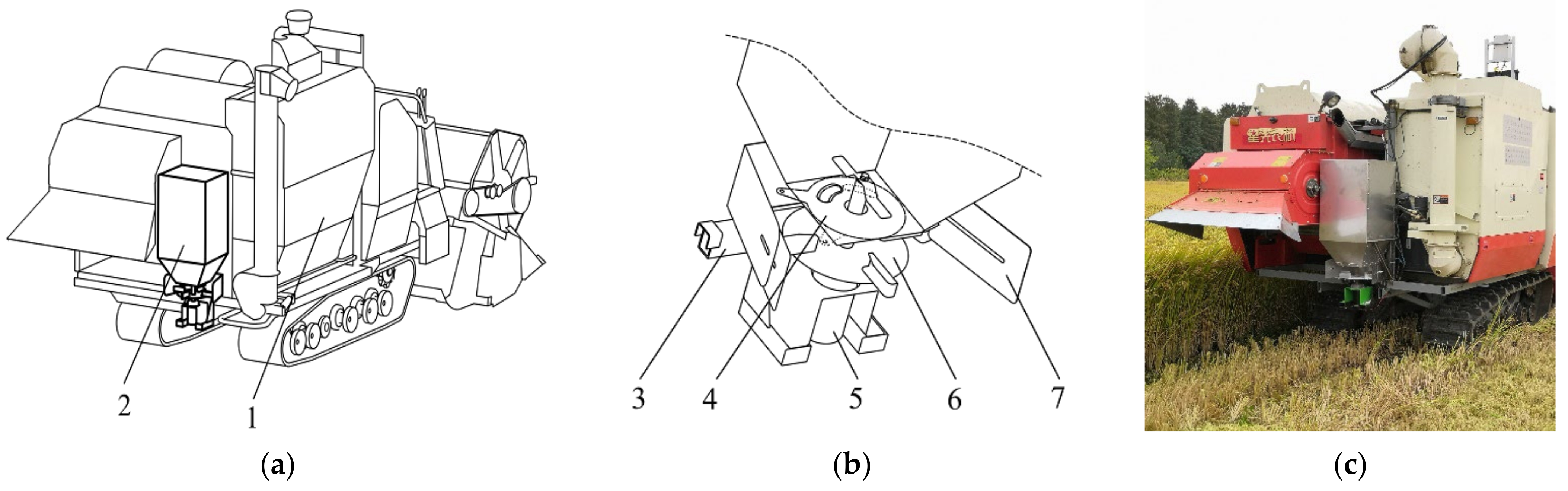
2.1. Overall Design and Working Principle of the Spreader

Figure 1 shows the overall structure of the developed centrifugal disc spreader on combine harvester. The spreader mainly comprises a fertilizer box, an adjustment disc, a centrifugal disc, a DC motor, and a shield, along with other minor parts. The designed spreader is matched with Thinker 4LZ-5.0Z tracked combine harvester with a cutting width of 2.0 m and a forward speed of 0~1.24 m/s. The power of the fertilizer spreader is provided by a DC motor, and the disc rotational velocity can be adjusted without steps in real time. The pull-wire fertilizer volume adjustment plate can change the position of feed gate hold and adjust the fertilizer discharge. The feed gate hold can be closed and the fertilizer spreading stopped when the tracked combine harvester is turning.
By the designed centrifugal disc spreader, harvesting and fertilizer spreading can be accomplished simultaneously. The range of fertilizer spreading is shown in Figure 2. Fertilizer needs to be sprayed on the harvested areas that have not been covered with straw to avoid spilling fertilizer on rice and straw, to ensure the quality of the grain and improving fertilizer utilization. The structural and operating parameters that affect the fertilizer spreading range and distribution pattern need to be investigated to meet the above requirements.

2.2. Spreader Parameters Design

2.2.1. Fertilizer Box

The spreader used in conjunction with the combine harvester and adding fertilizer exclusively during the harvesting S would significantly affect efficiency. Adding fertilizer during grain unloading would not take extra time and is the preferred way. Therefore, the fertilizer box volume needs to match the storage capacity of the combine harvester grain bin. The relationship between the fertilizer box volume and harvested area is:
V = k 1 S Q ρ p
where V is the volume of fertilizer box, m3; k1 is volume coefficient, 1.25; S is the harvested area in a single grain bin fill, m2; Q is the fertilizer quantity per area, kg/m2; and ρp is the fertilizer density, 1325 kg/m3.
The harvested area in a single grain bin fill is correlated with rice yield. The grain bin volume of the combine harvester used is 1.4 m3, and harvested area in a single grain bin fill is 1600~2200 m2 in general. In the planting pattern of rape undersowing rice, the fertilizer quantity per area is 0.06 kg/m2. The volume of the fertilizer box was calculated to be greater than 0.125 m3. The developed fertilizer box has a length, width, and height of 500 mm, 400 mm, and 800 mm, respectively. The actual volume of the fertilizer tank is 0.148 m3, which ensures sufficient fertilizer in the interval of grain unloading.

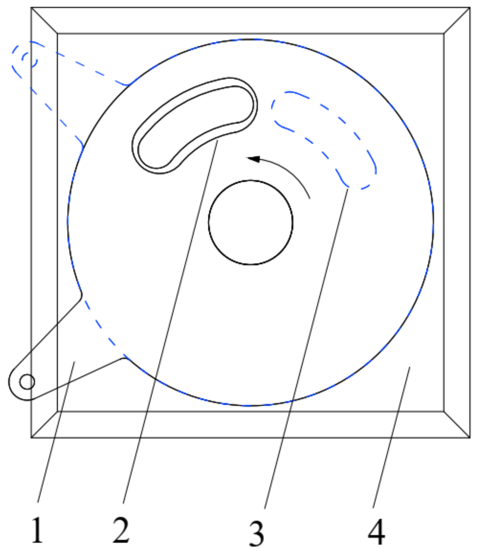
2.2.2. Fertilizer Flow-Regulating Device

As shown in Figure 3, by regulating the location of the feed gate hole in the moving plate relative to the feed gate hole in the fixed plate, changing the size of the feed gate opening could be adjusted, thereby adjusting the flow rate. The flow rate is [21]:
q = k 2 s v ρ p
where s′ is the area of feed gate hold, m2; v is the fertilizer flow speed, m/s; and k2 is the reliability coefficient of feed gate hold, 0.95.
The area of feed gate hold could be adjustable from 0 to 1.335 × 10⁻³ m3, corresponding to the flow rate in the range of 0~0.2 kg/s.

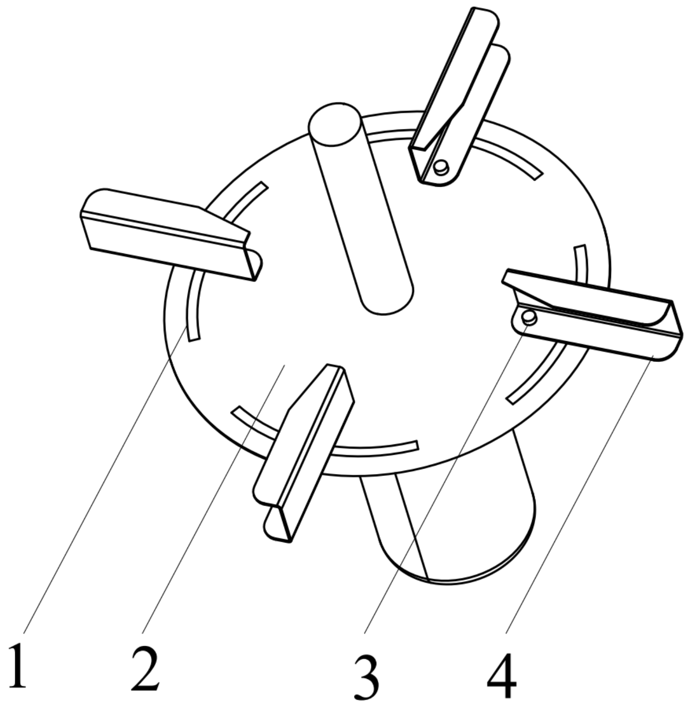
2.2.3. Centrifugal Disc

As shown in Figure 4, the centrifugal disc includes 4 adjustment screws, oriented at 90° from each other. The pitch angle relative to the distribution cover of a center-alignment generatrix, with an adjustable of −30°~30°, can be set by the adjustment screw and chute. The fertilizer particles, under the action of the centrifugal force, are scattered by the turning of the pitch vane, evenly distributing the fertilizer out over the edges of the centrifugal disc. In order to make the fertilizer have a radial velocity along with the centrifugal disc, the applied centrifugal force must be greater than sliding friction resistance, as follows:
μ m g m r 0 ω 2
where μ is the dynamic friction coefficient between fertilizer granule and centrifugal disc; m is the quantity of fertilizer granule, kg; ω is the rotational angular velocity of disc, rad/s; and r0 is the minimum distance between fertilizer granule and disc center.
According to Equation (3), the distance between the feed gate hold and the disc center is in the range of 55~75 mm.

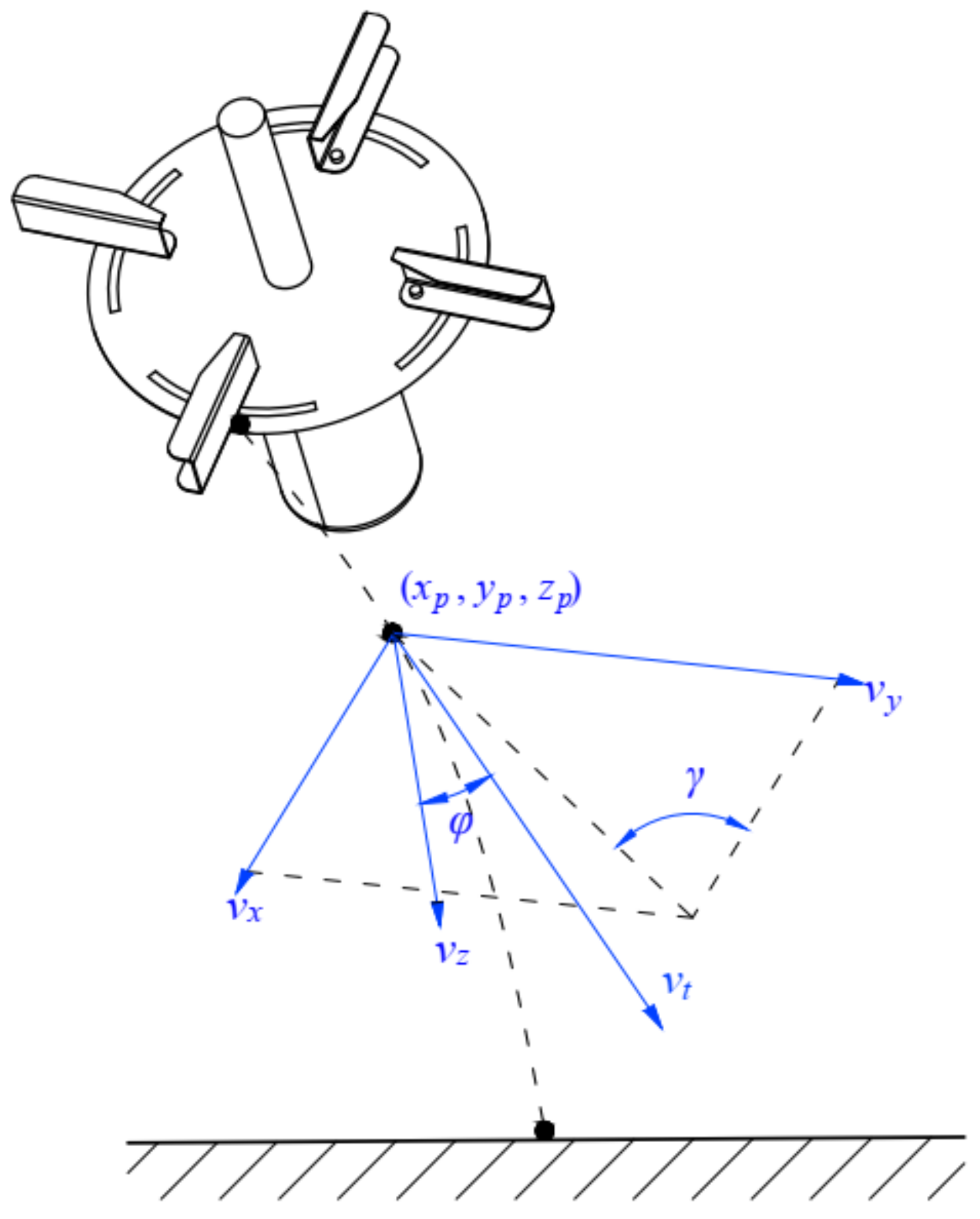
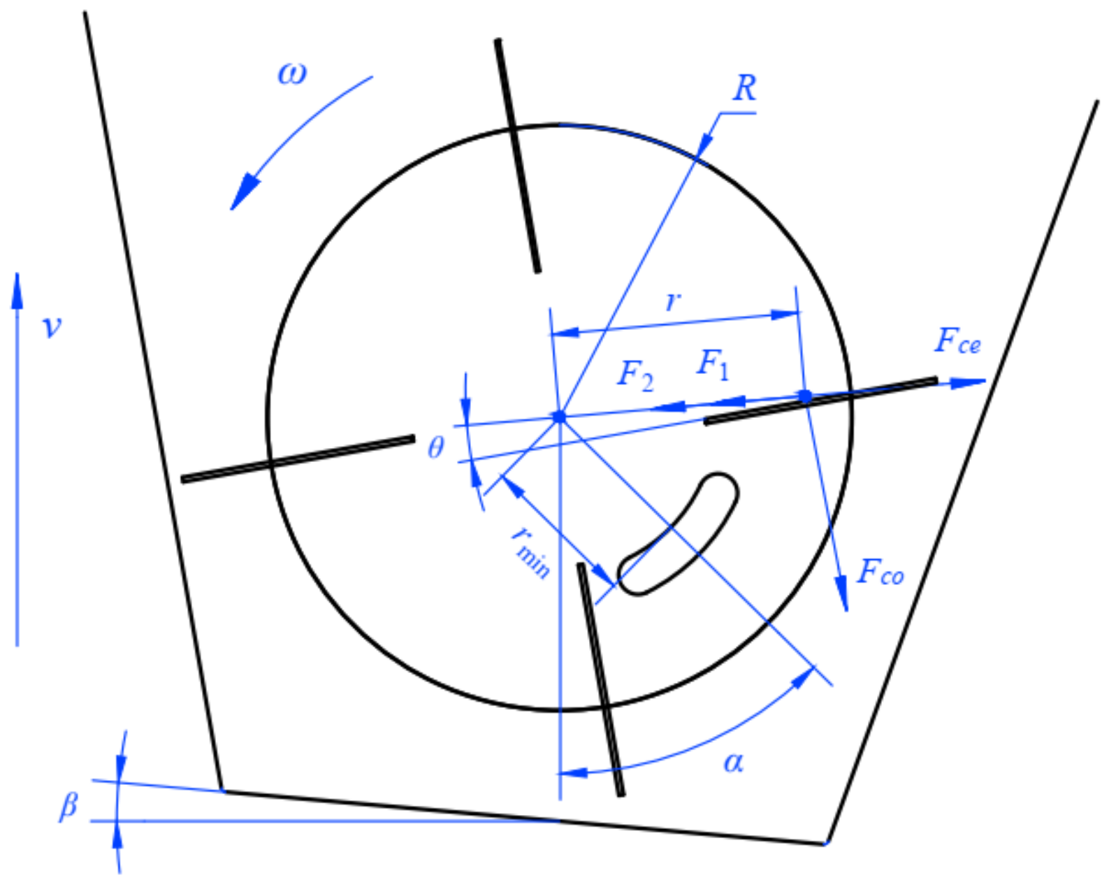
2.3. Kinematic Analysis of Fertilizer Particle

The kinetic characteristic analysis of fertilizer particles was mainly divided into two stages: the passive motion on the centrifugal disc and the active motion after leaving the disc. When on the centrifugal disc, the fertilizer particles are subject to the combined action of the gravity (G), the centrifugal force (Fce), the coriolis force (Fcor), the friction force (Ff) of the disc (F1), and the vane (F2). The applied forces on a fertilizer particle are shown in Figure 5.
The mechanics state of fertilizer particles can be expressed as:
G F c e F c o F 1 F 2 = m × g r ω d r d t s i n θ 2 r 2 ω d r d t μ 1 g 2 μ 2 ω d r d t
where r is the distance from the particle to the center of rotation, m; ω is the rotational angular velocity of the disc, rad/s; θ is the pitch angle of the vane, °; μ1 is the coefficient of friction between the pitch vane and the particle; and μ2 is the coefficient of friction between the disc and the particle.
According to Newton’s second law, the motion equation for the particle is:
m d 2 r d 2 t = m r ω d r d t s i n θ 2 r c o s θ μ m g 2 μ m ω d r d t
In the process of fertilizer spreading, the fertilizer rotates with the centrifugal disc. After contact with the vanes, the velocity is the synthesis of the linear motion along the radial direction of the vanes and the circular motion along the central axis of the centrifugal disc. The kinematic equation of the fertilizer particles on the centrifugal disc can be obtained from the geometric relationship and Equation (5):
d 2 r d 2 t = s i n 2 θ c o s θ r d r d t 2 2 μ ω + 2 ω s i n θ c o s θ d r d t + r ω 2 μ g
The boundary condition of the passive motion on the centrifugal disc is the distance from the particle to the center of rotation (r) equal to the centrifugal disc radius (R), after leaving the disc and starting active motion. After the fertilizer particle leaves the conical disc and the pitch vane, it is subject to the effects of gravity and air resistance, among other factors, causing it to follow a helically curved trajectory through the air, as shown in Figure 6.
The velocity of the particle in each direction can be described by
v x v y v z = v t c o s φ c o s γ c o s φ s i n γ s i n φ = d x p d t d y p d t d z p d t
where vt is the fertilizer speed at time t, m/s; φ is the angle between fertilizer speed and z-axis at time t, °; and γ is the angle between fertilizer speed and x-axis at time t, °.
According to the principles of aerodynamics, the air resistance Fa acting on the fertilizer particle moving in the air is:
F a = 1 2 ρ a C S p v t 2
where C is the coefficient of air resistance; ρa is the air density, kg/m3; and Sp is the windward area of the particle, m2.
The acceleration of the particle in each direction can be deduced from Newton’s second law:
m d 2 x p d t 2 d 2 y p d t 2 d 2 z p d t 2 = F a c o s φ c o s γ F a c o s φ s i n γ m g F a s i n φ
The windward area and the mass of the fertilizer particle are:
S p = 1 4 π d p 2
m = 1 6 ρ p d p 3
where dp is fertilizer particle diameter, m.
By considering Equations (8)–(11), the movement status of the fertilizer particle after leaving the disc is:
d 2 x p d t 2 d 2 y p d t 2 d 2 z p d t 2 = 3 4 × C ρ a d ρ p d x p d t 2 + d y p d t 2 + d z p d t 2 d x p d t d y p d t d z p d t + 0 0 g
According to Equations (7) and (12), the key factors affecting fertilizer distribution include feed gate hold position angle α, shield angle β, vane pitch angle θ, and disc rotational angular velocity ω.

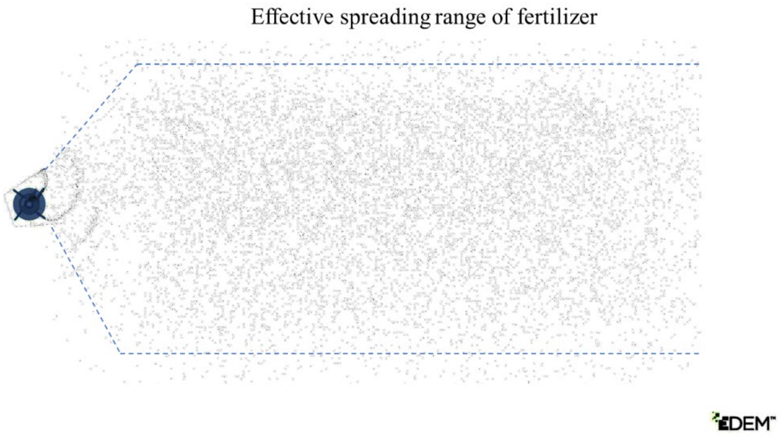
2.4. Analysis of Fertilizer Spreading Process Based on DEM

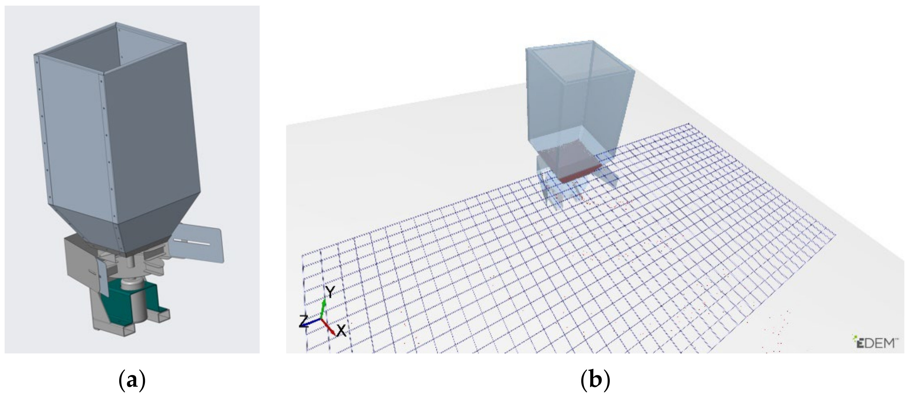
2.4.1. DEM Model for Simulation of the Centrifugal Disc Spreader

The distribution behavior of the fertilizer particle population under the action of the fertilizer spreader was further studied by DEM. The 3D computer-aided design (CAD) models of the centrifugal disc spreader were imported into the DEM software EDEM 2018 (DEM Solutions Limited, Edinburgh, UK). The 3D simulation models and boundary conditions were determined by geometry parameters and working parameters, respectively. The hard sphere model and Hertz–Mindlin (no slip) model were chosen as the particle model and particles contact model in the EDEM software for fertilizer. The simulation time step, environmental gravitational acceleration, and preservation interval were 0.5 × 10⁻⁶ s, 9.8 m·s−2, and 0.01 s, respectively.
The fertilizer is a spherical granule with a sphericity of 88%, so the spheres can be used instead of the fertilizer particles in the imitation model [22,23]. The fertilizer particle model was set to a mean diameter of 4 mm, with a normal distribution of model diameters and a standard deviation of 0.05 mm, and the average grain mass per thousand was 33.14 g. The fertilizer spreader made of stainless steel and the related contact mechanical characteristic parameters between the spreader disc and the fertilizer particles are shown in Table 1 [24,25].
The height and forward speed of the fertilizer spreader relative to the ground were set at 0.5 m and 1 m/s, respectively. The grid bin group counting grid was at 0.5 m below the fertilizer spreader, each network size was 100 mm × 100 mm, with 800 calculating grids in 20 rows and 40 columns in a 2 m × 4 m collection rectangle, as shown in Figure 7. The particle factory was set up for 10 kg of particles generated statically. The simulation time was 6 s to ensure that the centrifugal disc spreader was far enough away from the grid bin group that no more fertilizer falls into it.

2.4.2. Simulation Design

Single-factor and cross-factor simulations were carried out to study the influence of the structural and movement parameters of the spreader on the distribution pattern of fertilizer. The simulation test was conducted with feed gate hold position angle α, shield angle β, vane pitch angle θ, and disc rotational angular velocity ω as test factors, as shown in Figure 8. The particle effective spreading swath width and transverse distribution coefficient of variation in the effective swath width were calculated to assess the spreading performance of the applicator. In the simulations, the structure of the centrifugal disc spreader was changed by adjusting the geometry parameters. The coefficient of variation is given as follows:
C V = 1 n i = 1 n m i m ¯ 2 m ¯ × 100 %
where CV is the coefficient of variation of the particle distribution, m ¯ is the average quality of the fertilizer particles, mi is the quality of the fertilizer particles in the ith collection pan, and n is the total number of collecting pans.
Single-factor trials were conducted for the above four factors, each factor consisted of five levels, and 20 sets of trials were conducted. The simulation design of single-factor trials is shown in Table 2.
The distribution pattern of fertilizer particles is influenced by multiple factors, and there is an interaction between them. Therefore, cross-factor simulations were conducted by using a four-factor, three-level quadratic orthogonal regression rotated combination test. A total of 29 sets of trials were conducted with five central sites selected according to the Box–Behnken experimental design. The test codes are shown in Table 3.
The influence of each factor on the fertilizer distribution was quantified by the contribution ratio K, calculated as [26]:
K j = δ j + 1 2 i = 1 δ i j + δ j 2 , j = 1 , 2 , 3 , i j
δ = 0 , F 1 1 1 F , F > 1
where F is the F-value of each term in the regression equation, δ is the assessment value of the regression term on the F-value, and Kj is the contribution rate of each factor.

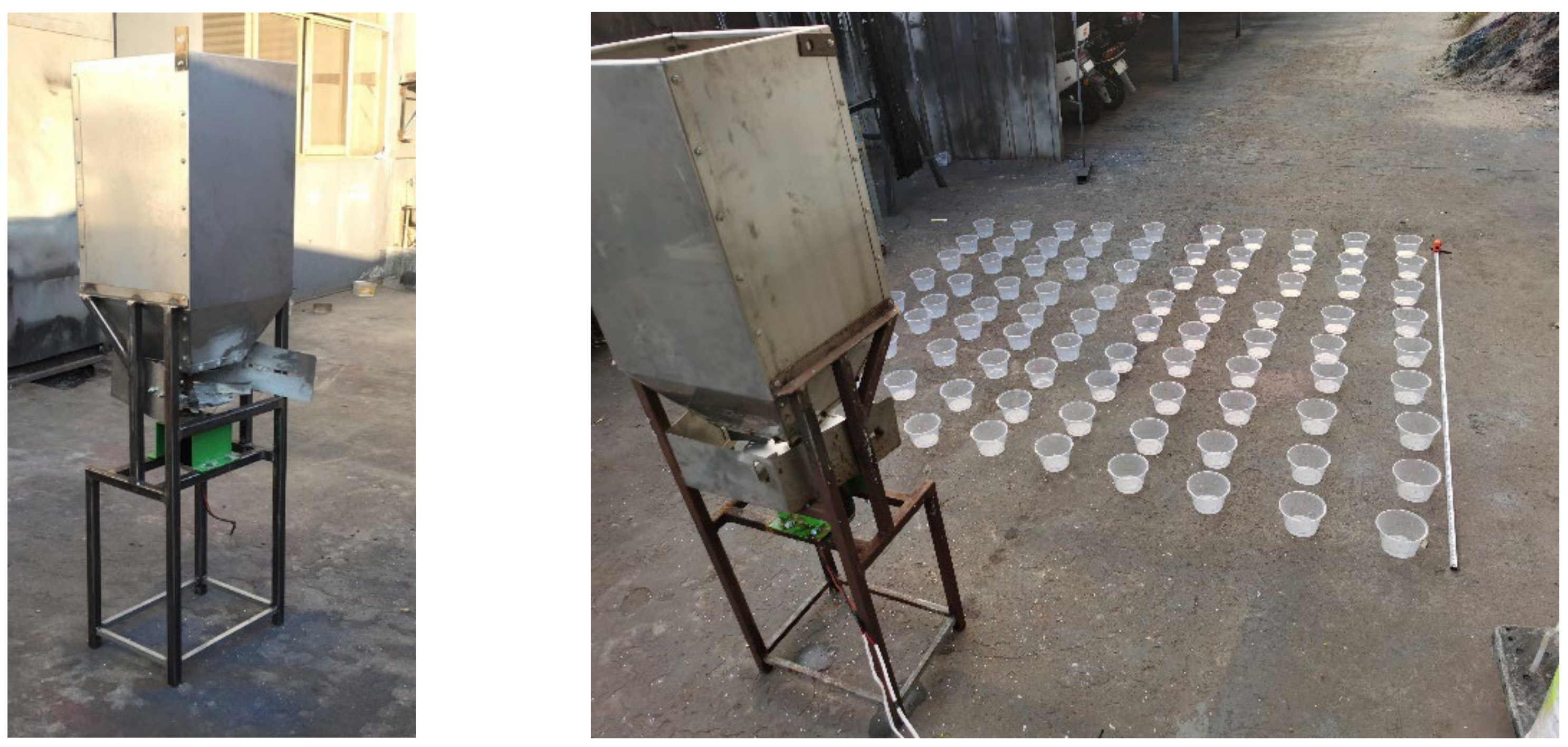
2.5. Bench Test Method

The test methods and indices were complied with the standards ISO 5690 and ASAE S341.2 [27,28]. The simulation tests were examined by the two-dimensional matrix method and the effect of fertilizer spreading was tested. The cutting width of the tracked combine harvester is 2.0 m, so the target effective spreading width of the fertilizer spreader is 2 m too. The lateral range of the bench test splice needs to be slightly more than 2.0 m to ensure the accuracy of the splice. Since the track gauge is smaller than the fertilizer spreading range, a static test was used. As shown in Figure 9, in the collection area of 2.4 m × 2.4 m, 9 × 9 collection pans were placed with a diameter of 170 mm and a depth of 90 mm, with horizontal and vertical spacing of 300 mm. The vertical distance between the cassette matrix and the fertilizer spreader was 1.2~3.6 m. The collection pans were evenly spaced with sand to avoid fertilizer bouncing out. The quality of the fertilizer granules in each collection pan was evaluated to characterize the fertilizer transverse distribution. At the same time, a static simulation test was carried out with the same parameters. The simulation tests were checked by comparison with the results bench test.

3. Results and Discussion

3.1. Single-Factor Simulation

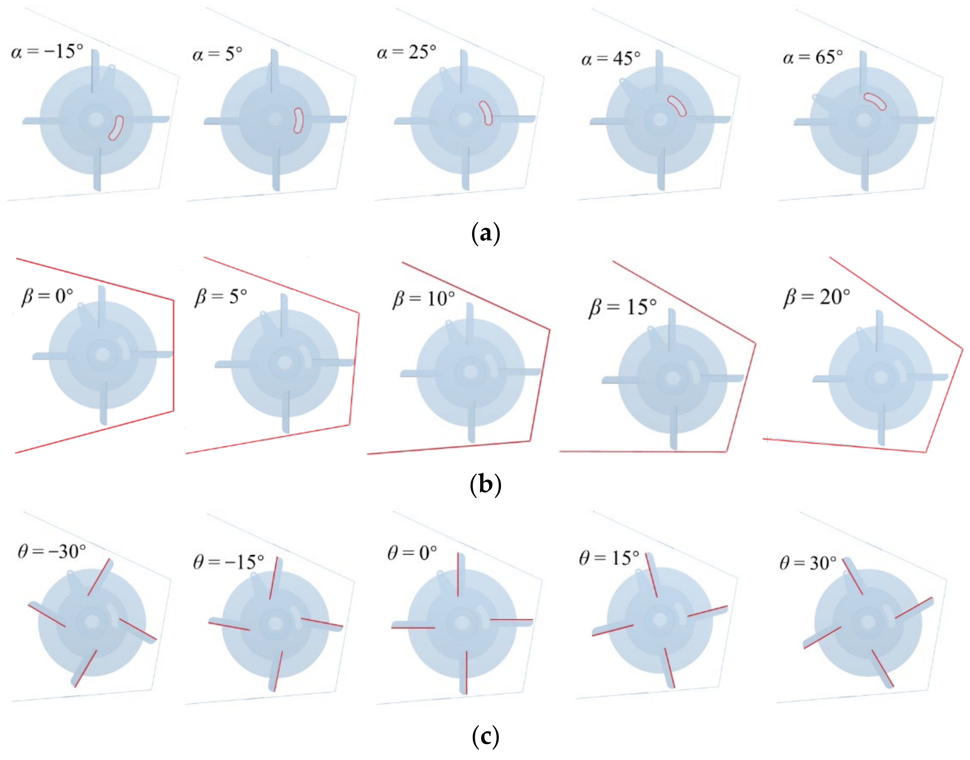
3.1.1. Effects of the Feed Gate Hold Position Angle

The effects of feed gate hold position angle on the spreader performance were investigated. Figure 10a shows the fertilizer quality distribution along the lateral distance at different feed gate hold position angles, and Figure 10b shows the variations of effective swath width and Cv in the effective swath width along with the feed gate hold position angle α. Under test conditions with β = 10°, θ = 10°, ω = 180 rpm, and the feed gate hold position angle of −15°~65° in increments of 20°, the effective spreading swath width increases and then decreases with the increase of the feed gate hold position angle. The distribution peak area makes gradual movements to the left. The transverse distribution coefficient of variation in the effective swath width decreases then increases with the increase of the feed gate hold position angle. When, α = 25°, the Cv is minimum, i.e., 19.9%. When α = −15°, the Cv is maximum, i.e., 38.2%. This may be because the drop-in position determines the starting movement location and the departure position of the fertilizer from the centrifugal disc, thus influencing the distribution.

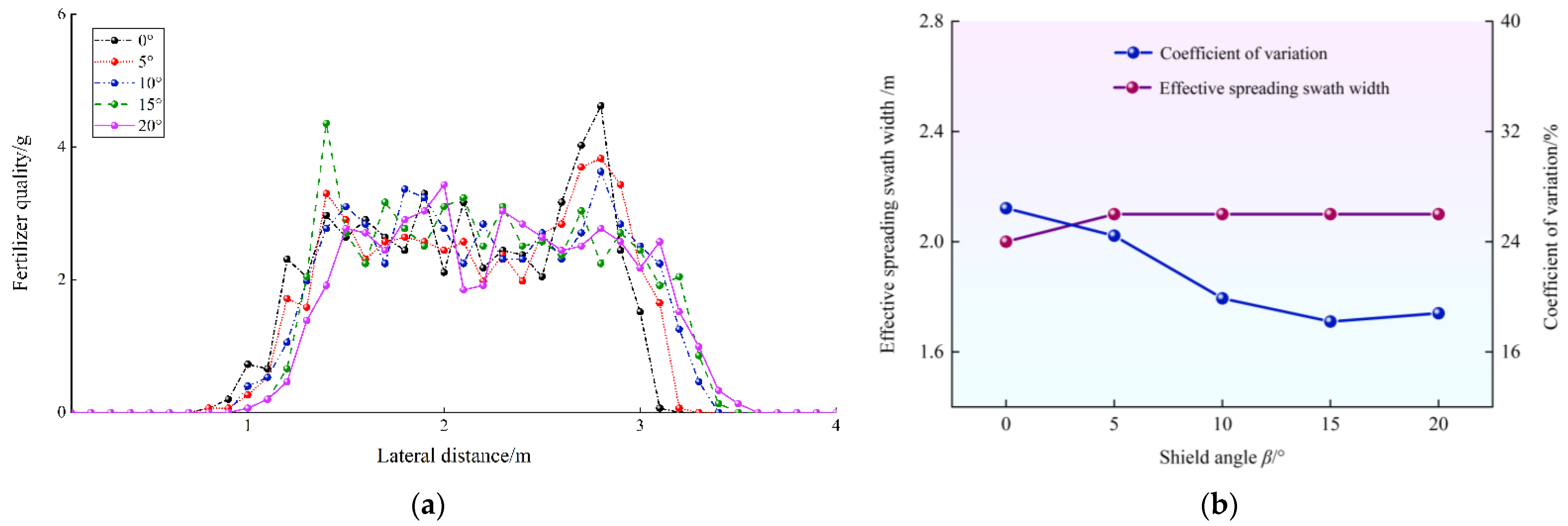
3.1.2. Effects of the Shield Angle

The effects of shield angle on the spreader performance are shown in Figure 11. The shield angle β did not affect the effective throwing width of the fertilizer but influenced the overall distribution position and local accumulation of the fertilizer. When β ≤ 5°, the fertilizer was distributed more along the right-hand side of the shield, and when the β ≥ 15°, the fertilizer was distributed more along the left-hand side of the baffle. The reason for this may be that the fertilizer changes its direction of movement after an elastic collision with the shield. The overall distribution of fertilizer was to the left when β was small and to the right when β was large. The transverse distribution coefficient of variation in the effective swath width decreases with the increasing of shield angle β. When, β = 15°, the Cv is minimum, i.e., 18.2%. When β = 0°, the Cv is maximum, i.e., 26.4%. Therefore, due to the direction of the initial velocity of the fertilizer particles and the collision effect with the shield that needs to constrain the spreading area, the baffles on both sides should not be symmetrically distributed.

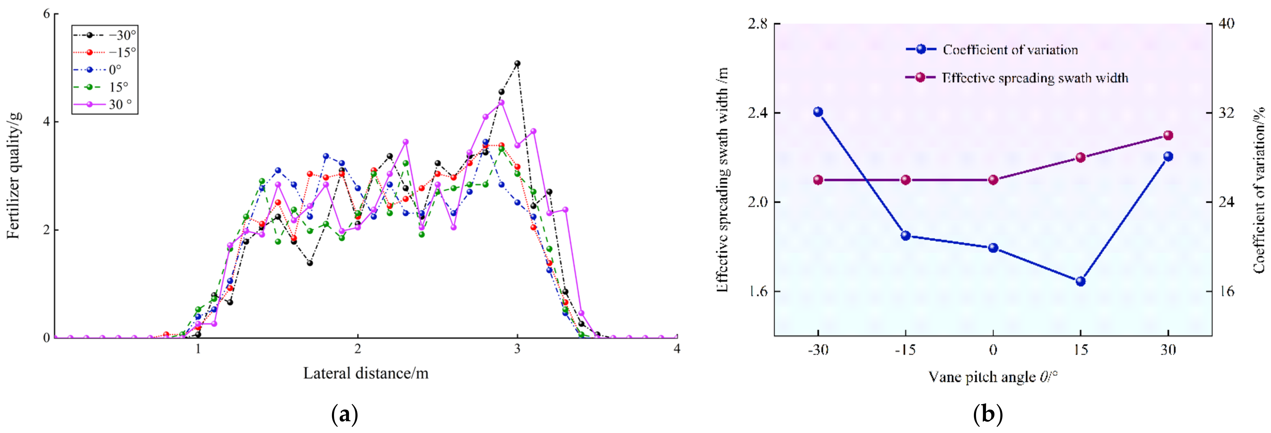
3.1.3. Effects of the Vane Pitch Angle

The effects of vane pitch angle on the spreader performance are shown in Figure 12. From Figure 12a, the excessive vane pitch angle θ results in an accumulation of fertilizer on one side, while smaller blade angles provide a more even distribution. As can be seen in Figure 12b, the Cv is significantly higher when θ is −30° and 30° than in the range of [−15, 15]. When θ = 15°, the Cv is minimum, i.e., 16.9%. When θ = −30°, the Cv is maximum, i.e., 32.1%. This may be because the vane pitch angle affects the friction force of the vane (F2 in Figure 5) and the fertilizer velocity (vt in Figure 6). When θ ≤ 0°, the effective swath width does not change much but increases with the increase of the vane pitch angle when θ ≥ 0°.

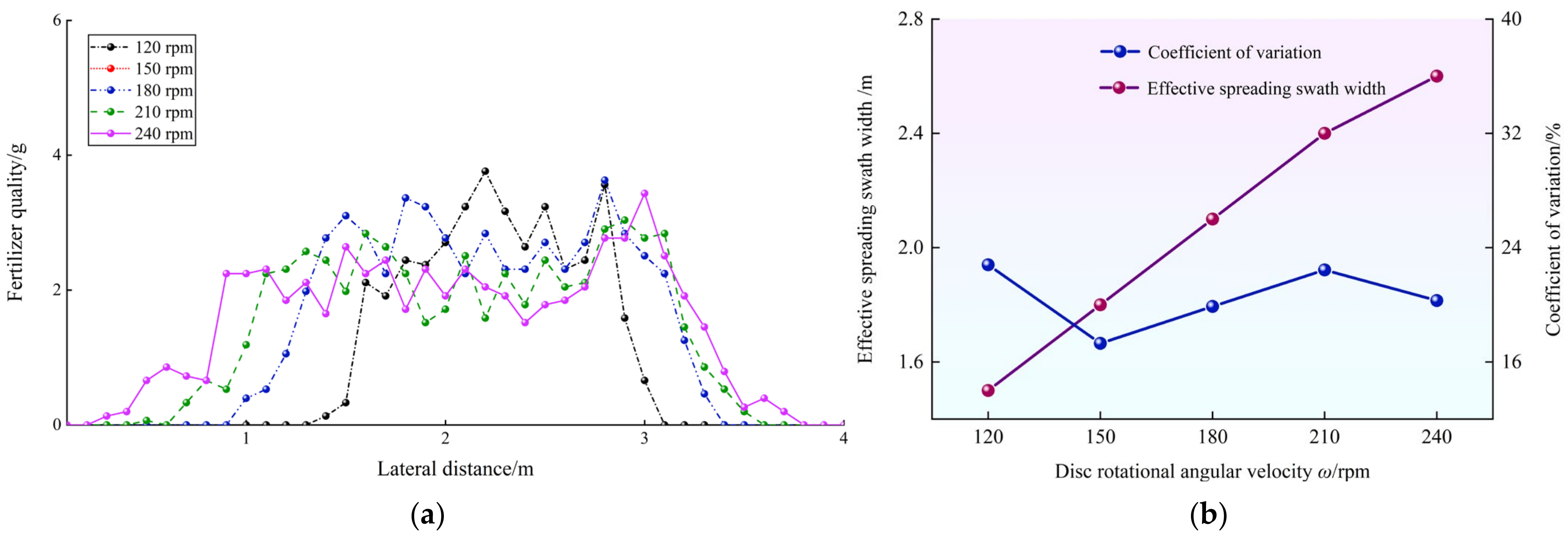
3.1.4. Effects of the Disc Rotational Angular Velocity

The effects of disc rotational angular velocity on the spreader performance are shown in Figure 13. The effective swath width varies very significantly and increases with the speed of the centrifugal disc. The Cv decreases and then increases as the speed of the centrifugal disc increases. When ω = 150 rpm, the Cv is minimum, i.e., 17.3%. When ω = 210 rpm, the Cv is maximum, i.e., 22.4%. This is mainly because as the speed of the centrifugal disc increases, the initial speed of the fertilizer increases, and the effective swath width increases. Therefore, it is very important to have a suitable disc rotational angular velocity to control the effective swath width.

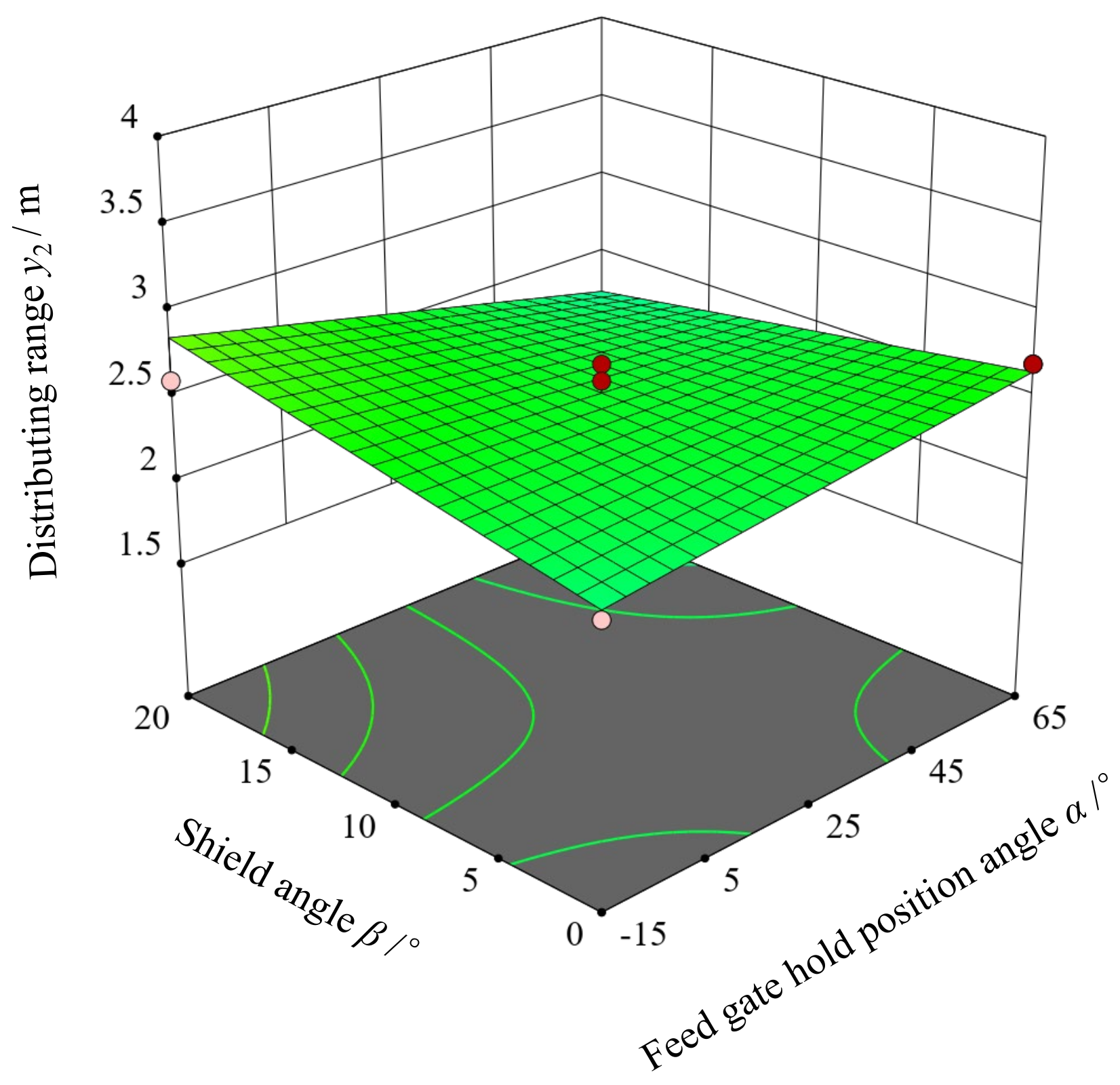
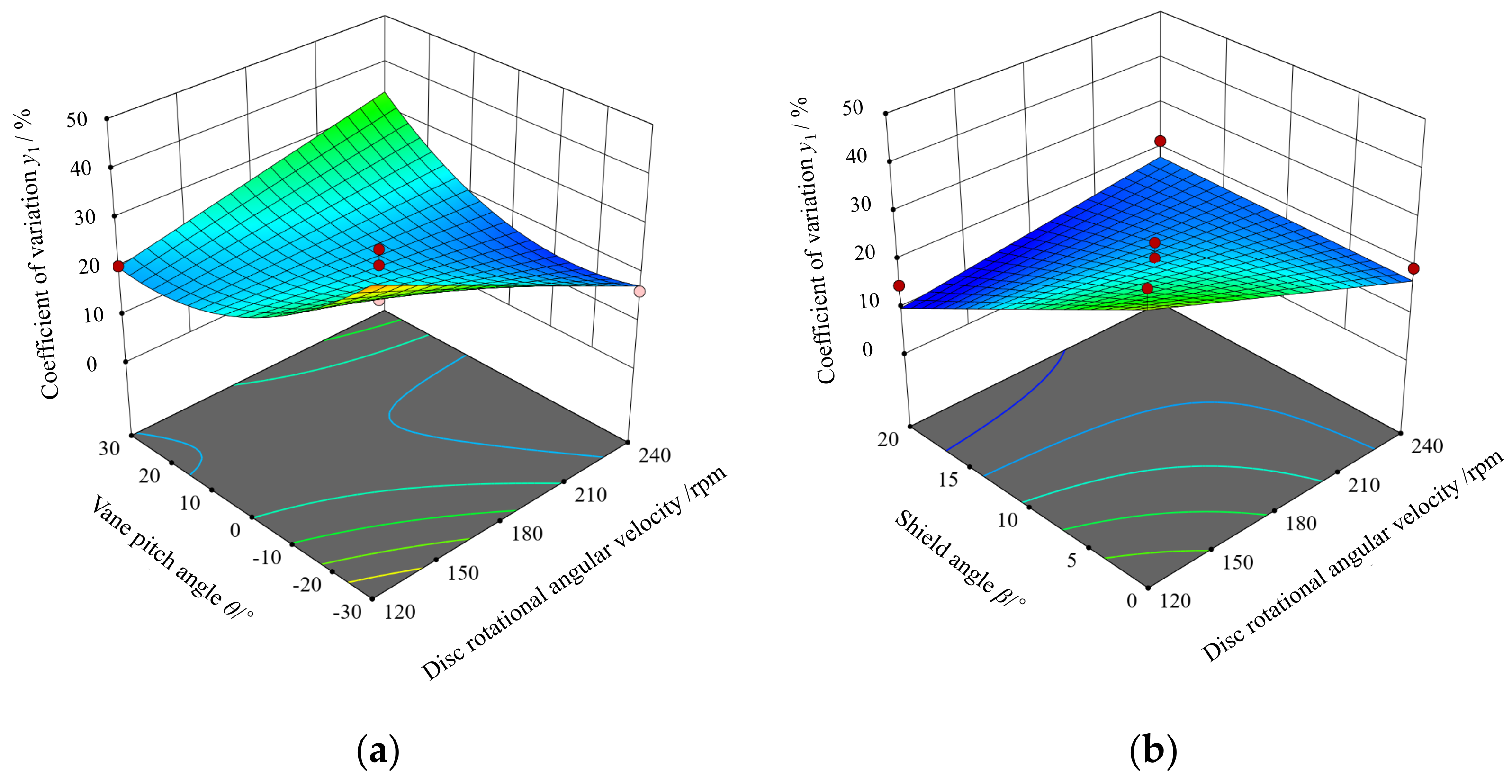
3.2. Cross-Factor Simulation

The result of the cross-factor simulation is shown in Table 4. Quadratic multivariate fitting of the experimental results was carried out by applying Design-Expert 12 software, and ANOVA and regression coefficient significance tests were carried out for the regression models. The results are shown in Table 5.
According to the quadratic multi-variate fitting regression ANOVA results of the coefficient of variation y1, the regression model p-value 0.0014 < 0.01 was highly significant and the out-of-fit p-value 0.1349 > 0.05 was not significant. It indicates that the model can correctly reflect the relationship among y1 and A, B, C, and D, as well as predicting test results. Among them, the interaction factors BC, A2, and C2 were highly significant, and A, D, and BD were significant. After excluding the insignificant factors, the quadratic regression model of the coefficient of variation y1 is:
y1 = 0.2111 − 0.0444 A − 0.0343 B − 0.0213 C − 0.0705 D + 0.1019 BC + 0.0751 BD + 0.1169 A2 + 0.0806 C2
According to Equations (14)–(16), the contribution ratios of each factor to y2 were Ky1A = 1.80, Ky1B = 1.59, Ky1C = 1.66, and Ky1D = 1.84, respectively. The order of the influence ranking was D > A > B > C. The effect of interaction factors on variable coefficient is shown in Figure 14. When A and D are at the center level (25°and 10°), y1 increases with the increase of B and decreases then increases with the increase of C. There exists a certain value of C that makes y1 minimum. The response surface curve changes faster along the B direction, and the effect of disc rotational angular velocity on the coefficient of variation is more significant than that of vane pitch angle. When A and C are at the center level (25° and 0°), y1 decreases with the increase of B and increases then decreases with the increase of D. There exists a certain value of D that makes y1 maximum. The response surface curve changes faster along the D direction, and the effect of shield angle on the coefficient of variation is more significant than that of disc rotational angular velocity.
According to the quadratic multi-variate fitting regression ANOVA results of the distributing range y2, the regression model p-value < 0.01 was highly significant and the out-of-fit p-value 0.0688 > 0.05 was not significant. It indicates that the model can correctly reflect the relationship among y2 and A, B, C and D, as well as predict test results. Among them, the interaction factor B was highly significant, and AD and C2 were significant. After excluding the insignificant factors, the quadratic regression model of the distributing range y2 is:
y2 = 2.53 − 0.075 A + 0.8083 B − 0.075 C + 0.025 D − 0.225 AD + 0.2123 C2
According to Equations (14)–(16), the contribution ratios of each factor to y2 were Ky2A = 1.75, Ky2B = 2.04, Ky2C = 1.76, and Ky2D = 0.42, respectively. The order of the influence ranking was B > A > C > D. The effect of interaction factors on variable coefficient is shown in Figure 15. When B and C are at the center level (180 rpm and 0°), y2 decreases with the increase of A and increases then increases with the increase of D. The response surface curve changes faster along the A direction, and the effect of feed gate hold position angle on the distributing range is more significant than that of shield angle.

3.3. Optimization Design

The fertilizer spreading range is required to be consistent with the harvester cutting width, i.e., y2 = 2.0 m, and the coefficient of variation y1 is as small as possible. According to the above requirements, a multi-objective optimization model of centrifugal disc spreader was established:
m i n y 1 y 2 = 2.0 s . t . 15 ° A 15 ° 120 r / min B 240 r / min 30 ° C 30 ° 0 ° D 20 °
The optimal combination of parameters was A = 24.93°, B = 153.13 r/min, C = 13.88°, and D = 18.58°, respectively. The coefficient of variation and spreading range were 12.36% and s 2.0 m at this parameter combination, respectively. These were established with comprehensive consideration of the actual manufacture degree, determine feed gate hold position angle 25°, disc rotational angular velocity 150 rpm, vane pitch angle 14°, and shield angle 19°, respectively. The result of fertilizer distribution of centrifugal disc spreader is shown in Figure 16.

3.4. Bench Test

Static fertilizer spreading simulation tests and bench tests were conducted using the optimized parameter combinations. As shown in Figure 17, the distribution of fertilizer from simulation tests and bench tests was consistent. The coefficient of variation of fertilizer lateral distribution was 13.1% for the simulation test and 14.6% for the bench test. The error of simulation test was 10.3%, which indicates that the simulation result was reliable. The developed centrifugal disc spreader can meet the needs of fertilizer spreading for rape undersowing rice.

4. Conclusions

A centrifugal disc spreader on tracked combine harvester was developed for rape undersowing rice fertilizer spreading. Based on DEM analysis, an analytical model of the fertilizer distributor was constructed to optimize the parameters and verified by bench tests. In addition, the effect of centrifugal disc spreader structure on fertilizer distribution was studied to meet the special requirements of rape undersowing rice and harvesting. The bench test was conducted to verify the simulation model. The result showed that the spreading range of simulation test was 2.0, which was consistent with the bench test, and the coefficient of variation of fertilizer lateral distribution was 13.1%, with an error of 10.3% compared to the bench test. The DEM method used in this paper can provide technical reference for the design of fertilizer spreader and provide new ways to promote accurate and efficient spreading of fertilizer.
Furthermore, the effect of the single structure and interaction factors of the spreader on the distribution pattern of fertilizer obtained in this study can be used to quantitatively analyze and predict the effective spreading range and spreading uniformity. In the future, an automatic variable rate spreader system according to combine harvester forward speed and cutting width in consideration of the various types of combine harvesters should be investigated.

Author Contributions

Conceptualization, Z.G. and S.M.; methodology, Z.G.; software, T.J.; validation, H.L. and M.J.; formal analysis, Z.G.; investigation, Z.G.; resources, Z.G.; data curation, Z.G.; writing—original draft preparation, Z.G.; writing—review and editing, S.M.; visualization, C.W.; supervision, M.Z. and C.W. project administration, S.M.; funding acquisition, Z.G. All authors have read and agreed to the published version of the manuscript.

Funding

This research was funded by Natural Science Foundation of Jiangsu Province (BK20210040), China Postdoctoral Science Foundation (2021M702503), and China Agriculture Research System of MOF and MARA (CARS-12).

Data Availability Statement

The data presented in this study are available on request from the authors.

Acknowledgments

The authors thank the editor and anonymous reviewers for providing helpful suggestions for improving the quality of this manuscript.

Conflicts of Interest

The authors declare no conflict of interest.

References

  1. Liu, C.; Feng, Z.C.; Xiao, T.H.; Ma, X.M.; Zhou, G.S.; Huang, F.H.; Li, J.N.; Wang, H.Z. Development, potential and adaptation of Chinese rapeseed industry. Chin. J. Oil Crop Sci. 2019, 41, 485–489. [Google Scholar]
  2. Fang, Y.T.; Ren, T.; Zhang, S.T.; Liu, Y. Rotation with oilseed rape as the winter crop enhances rice yield and improves soil indigenous nutrient supply. Soil Tillage Res. 2021, 212, 105065. [Google Scholar] [CrossRef]
  3. Wang, H.N.; Yang, G.T.; Wang, K.C.; Zhao, C.K. Oilseed rape straw returning changes soil reducibility and affects the root and yield of rice in the rape-rice rotation field at Sichuan Basin area of China. Agron. J. 2020, 112, 4681–4692. [Google Scholar] [CrossRef]
  4. Yuan, Y.; Wang, B.; Zhou, G.S.; Liu, F.; Huang, J.S.; Kuai, J. Effects of Different Sowing Dates and Planting Densities on the Yield and Stem Lodging Resistance of Rapeseed. Sci. Agric. Sin. 2021, 54, 1613–1626. [Google Scholar]
  5. Lei, H.X.; Chen, A.W.; Zhang, C.S.; Luo, K.S.; Chen, X.G. Effect of Symbiosis Period and Seeding Amount on Growth and Yield of Rapeseed Undersowing Rice. Acta Agron. Sin. 2011, 37, 1449–1456. [Google Scholar] [CrossRef]
  6. Kuai, J.; Du, X.Z.; Hu, M.; Zeng, J.X.; Zuo, Q.S.; Wu, J.S.; Zhou, G.S. Effect of Symbiosis Period and Seeding Amount on Growth and Yield of Rapeseed Undersowing Rice. Sci. Agric. Sin. 2016, 42, 591–599. [Google Scholar]
  7. Zheng, W.; Xiao, G.B.; Lv, W.S.; Li, Y.Z.; Chen, M.; Huang, T.B.; Xiao, X.J.; Wu, Y.; Ye, C. Effect of sowing rate on population growth of interplanting rapeseed in double—Cropping rice. Chin. J. Oil Crop Sci. 2018, 40, 227–232. [Google Scholar]
  8. Fulton, J.P.; Shearer, S.A.; Higgins, S.F.; Mcdonald, T.P. A method to generate and use as-applied surfaces to evaluate variable-rate fertilizer applications. Precis. Agric. 2013, 14, 184–200. [Google Scholar] [CrossRef]
  9. Villette, S.; Cointault, F.; Piron, E.; Chopinet, B. Centrifugal spreading: An analytical model for the motion of fertilizer particles on a spinning disk. Biosyst. Eng. 2005, 92, 157–164. [Google Scholar] [CrossRef]
  10. Cool, S.; Pieters, J.G.; Mertens, K.C.; Nuyttens, D.; Hijazi, B.; Dubois, J.; Cointault, F.; Vangeyte, J. Image Based Techniques for Determining Spread Patterns of Centrifugal Fertilizer Spreaders. Agric. Agric. Sci. Proc. 2015, 7, 59–63. [Google Scholar] [CrossRef] [Green Version]
  11. Cool, S.R.; Vangeyte, J.; Mertens, K.C.; Nuyttens, D.R.; Sonck, B.R.; Gucht, T.C.; Pieters, J.G. Comparing different methods of using collecting trays to determine the spatial distribution of fertiliser particles. Biosyst. Eng. 2016, 150, 142–150. [Google Scholar] [CrossRef]
  12. Han, C.W.; Lee, S.Y.; Hong, Y.K.; Kweon, G.Y. Development of a variable rate applicator for uniform fertilizer spreading. Int. J. Agric. Biol. Eng. 2019, 12, 82–89. [Google Scholar] [CrossRef]
  13. Liu, X.D.; Ding, Y.C.; Shu, C.X.; Wang, K.Y.; Liu, W.P.; Wang, X.P. Mechanism Analysis and Test of Disturbance and Blockage Prevention of Spiral Cone Centrifugal Fertilizer Apparatus. Trans. Chin. Soc. Agric. Mach. 2020, 51, 44–54. [Google Scholar]
  14. Liedekerke, P.V.; Tijskens, E.; Dintwa, E.; Rioual, F.; Vangeyte, J.; Ramona, H. DEM simulations of the particle flow on a centrifugal fertilizer spreader. Powder Technol. 2009, 190, 348–360. [Google Scholar] [CrossRef]
  15. Cool, S.; Pieters, J.; Mertens, K.C.; Hijazi, B.; Vangeyte, J. A simulation of the influence of spinning on the ballistic flight of spherical fertiliser grains. Comput. Electron. Agric. 2014, 105, 121–131. [Google Scholar] [CrossRef]
  16. Shi, Y.Y.; Chen, M.; Wang, X.C.; Odhiambo, M.O.; Ding, W.M. Numerical simulation of spreading performance and distribution pattern of centrifugal variable-rate fertilizer applicator based on DEM software. Comput. Electron. Agric. 2018, 144, 249–259. [Google Scholar]
  17. Zinkevičienė, R.; Jotautiene, E.; Juostas, A.; Comparetti, A.; Vaiciukevičius, E. Simulation of Granular Organic Fertilizer Application by Centrifugal Spreader. Agronomy 2021, 11, 247. [Google Scholar] [CrossRef]
  18. Liu, C.L.; Li, Y.N.; Song, J.N.; Ma, T.; Wang, M.M.; Zhang, C. Performance analysis and experiment on fertilizer spreader with centrifugal swing disk based on EDEM. Trans. Chin. Soc. Agric. Eng. 2017, 33, 32–39. [Google Scholar]
  19. Hu, Y.G.; Yang, Y.C.; Xiao, H.R.; Li, P.P. Simulation and Parameter Optimization of Centrifugal Fertilizer Spreader for Tea Plants. Trans. Chin. Soc. Agric. Mach. 2016, 47, 77–82. [Google Scholar]
  20. Ren, W.J.; Wu, Z.Y.; Li, M.L.; Lei, X.L.; Zhu, S.L. Desing an Experiment of UAV Fertilization Spreader System for Rice. Trans. Chin. Soc. Agric. Mach. 2021, 52, 88–98. [Google Scholar]
  21. Yang, W.W.; Fang, L.Y.; Luo, X.W.; Li, H.; Ye, Y.Q.; Liang, Z.H. Experimental study of the effects of discharge port parameters on the fertilizing performance for fertilizer distribution apparatus with screw. Trans. Chin. Soc. Agric. Eng. 2020, 36, 1–8. [Google Scholar]
  22. Yatskul, A.; Lemière, J.P.; Cointault, F. Comparative energy study of the air-stream loading systems of air-seeders. Eng. Agric. Environ. Food 2017, 11, 30–37. [Google Scholar] [CrossRef]
  23. Dun, G.Q.; Gao, Z.Y.; Liu, Y.X.; Ji, W.Y.; Liu, W.H. Optimization design of fertilizer apparatus owned arc gears based on discrete element method. Int. J. Agric. Biol. Eng. 2021, 14, 97–105. [Google Scholar] [CrossRef]
  24. Wang, L.; Xi, R.J.; Liao, Y.T.; Zhang, Q.S.; Xiao, W.L.; Liao, Q.X. Effects of land slope on seeding performance of a broad width precision no-tillage planter for rapeseed. Trans. Chin. Soc. Agric. Eng. 2020, 36, 11–21. [Google Scholar]
  25. Wen, X.Y.; Yuan, H.F.; Wang, G.; Jia, H.L. Calibration method of friction coefficient of granular fertilizer by discrete element simulation. Trans. Chin. Soc. Agric. Mach. 2020, 51, 115–122. [Google Scholar]
  26. Guan, Z.H.; Jiang, T.; Li, H.T.; Wu, C.Y.; Zhang, M.; Wang, G.; Mu, S.L. Analysis and test of the laying quality of inclined transportation rape windrower. Trans. Chin. Soc. Agric. Eng. 2021, 37, 59–68. [Google Scholar]
  27. American Society of Agricultural and Biological Engineers. Procedure for Measuring Distribution Uniform and Calibrating Granular Broadcast Spreaders; American Society of Agricultural and Biological Engineers: St. Joseph, MO, USA, 2006. [Google Scholar]
  28. ISO 5690-2-1984; Equipment for Distributing Fertilizers-Test Methods—Part 2: Fertilizer Distributors in Lines. International Organization for Standardization: Geneve, Switzerland, 1984.
Figure 1. Schematic structure of centrifugal disc spreader on tracked combine harvester. (a) Position of centrifugal disc spreader on tracked combine harvester; (b) schematic structure of centrifugal disc spreader; (c) physical picture of centrifugal disc spreader. (1) Tracked combine harvester, (2) fertilizer box, (3) frame, (4) fertilizer quantity adjustment regulator, (5) DC moto, (6) centrifugal disc, and (7) shield.
Agriculture 12 00562 g001
Figure 2. Relation among fertilizer spreading area, straw spreading area, and unharvested area.
Agriculture 12 00562 g002
Figure 3. Schematic structure of fertilizer flow regulating device. (1) Moving plate, (2) feed gate hold in fixed plate, (3) feed gate hold in moving plate, and (4) fixed plate.
Agriculture 12 00562 g003
Figure 4. Structure schematic of the centrifugal disc. (1) Vane, (2) output of the distribution cover, (3) chute, and (4) adjustment screw.
Agriculture 12 00562 g004
Figure 5. Analytical model of the mechanical state of fertilizer particles when on the centrifugal disc.
Agriculture 12 00562 g005
Figure 6. Kinematic model of fertilizer particle after leaving the disc.
Agriculture 12 00562 g006
Figure 7. Assembly and simulation drawing of centrifugal disc spreader. (a) 3D model; (b) simulation model.
Agriculture 12 00562 g007
Figure 8. The structural changes of centrifugal disc spreader. (a) Feed gate hold position angle α; (b) shield angle β; (c) vane pitch angle θ.
Agriculture 12 00562 g008
Figure 9. Bench test.
Agriculture 12 00562 g009
Figure 10. Effects of the feed gate hold position angle α. (a) Fertilizer quality distribution along with the lateral distance; (b) variations of effective swath width and Cv along with α.
Agriculture 12 00562 g010
Figure 11. Effects of the shield angle β. (a) Fertilizer quality distribution along the lateral distance; (b) variations of effective swath width.
Agriculture 12 00562 g011
Figure 12. Effects of the vane pitch angle θ. (a) Fertilizer quality distribution along the lateral distance; (b) variations of effective swath width and Cv along with θ.
Agriculture 12 00562 g012
Figure 13. Effects of the disc rotational angular velocity ω. (a) Fertilizer quality distribution along the lateral distance; (b) variations of effective swath width and Cv along with ω.
Agriculture 12 00562 g013
Figure 14. The effect of interaction factors on coefficient of variation. (a) y1 = f (25°, B, C, 10°); (b) y1 = f (25°, B, 0°, D).
Agriculture 12 00562 g014
Figure 15. The effect of interaction factors on distributing range.
Agriculture 12 00562 g015
Figure 16. Fertilizer distribution of centrifugal disc spreader.
Agriculture 12 00562 g016
Figure 17. Comparison of simulation test and bench test. (a) Result of simulation test; (b) result of bench test.
Agriculture 12 00562 g017
Table 1. DEM parameters used in the simulations.
ItemsParametersValues
ParticleDensity/(kg·m−3)1325
Poisson’s ratio0.25
Shear modulus/Pa2.86 × 107
SteelDensity/(kg·m−3)7850
Poisson’s ratio0.33
Shear modulus/Pa7.1 × 1010
Particle to particleElastic recovery coefficient0.28
Friction coefficient0.34
Friction coefficient0.21
Particle to steelElastic recovery coefficient0.41
Friction coefficient0.22
Friction coefficient0.33
Table 2. Simulation design of single-factor trials.
FactorFactor LevelFixed Level
12345
Feed gate hold position angle α−155254565β = 10°, θ = 10°, ω = 180 rpm
Shield angle β05101520α = 25°, θ = 10°, ω = 180 rpm
Vane pitch angle θ−30−1501530α = 25°, β = 10°, ω = 180 rpm
Disc rotational angular velocity ω/rpm120150180210240α = 25°, β = 10°, θ = 10°
Table 3. The test codes of cross-factor simulations.
LevelFeed Gate Hold Position Angle αDisc Rotational Angular Velocity ω/rpmVane Pitch Angle θShield Angle β
−1−15120−300
02518010
1652403020
Table 4. Cross-factor simulation result.
Test No.αω/rpmθβy1/%y2/m
1−1512001042.41.8
26512001019.21.5
3−1524001037.63.7
46524001023.93.2
525180−30037.62.7
62518030029.42.6
725180−302024.62.8
825180302025.02.8
9−151800042.22.3
10651800046.92.7
11−1518002023.02.6
126518002025.12.1
1325120−301049.32.6
1425240−301016.53.7
1525120301020.51.9
1625240301028.43.6
17−15180−301045.52.5
1865180−301037.42.6
19−15180301048.62.6
2065180301033.62.5
21251200043.01.7
22252400019.83.3
232512002014.81.8
242524002021.73.5
252518001014.02.7
262518001024.62.5
272518001015.82.5
282518001016.32.5
292518001021.32.6
Table 5. Analysis of variance for cross-factor simulation.
Sourcey1y2
Quadratic SumDfF-Valuep-ValueQuadratic SumDfF-Valuep-Value
Model0.3041145.55790.0014 **8.93441420.9236<0.0001 **
A0.023716.05960.0274 *0.067512.21310.1590
B0.014213.62270.07787.84081257.0765<0.0001 **
C0.005411.39290.25760.067512.21310.1590
D0.0596115.24130.0016 *0.007510.24590.6277
AB0.002210.57090.46240.010010.32790.5760
AC0.001210.30410.59000.010010.32790.5760
AD0.000210.04170.84110.202516.63930.0220 *
BC0.0415110.62560.0057 **0.090012.95080.1079
BD0.022515.76760.0308 *0.002510.08200.7788
CD0.001810.46520.50630.002510.08200.7788
A20.1008125.80210.0002 **0.139514.57480.0506
B20.001310.34060.56880.106813.50260.0823
C20.0506112.95930.0029 **0.268218.79280.0102 *
D20.007711.96340.18290.014110.46320.5073
Residual0.054714 0.427014
Lack of Fit0.0470102.43210.20310.3950104.93750.0688
Pure Error0.00774 0.03204
Cor Total0.358828 9.361428
Note: ** means highly significant (p < 0.01), * means significant (0.01 ≤ p < 0.05).
Publisher’s Note: MDPI stays neutral with regard to jurisdictional claims in published maps and institutional affiliations.

