Article

Design and Experiment of a Reciprocating Intermittent Chopping Device for Maize Straw Returning

1
College of Engineering, China Agricultural University, Beijing 100083, China
2
Hebei Nonghaha Agricultural Machinery Co., Ltd., Shijiazhuang 052560, China
*
Author to whom correspondence should be addressed.
Agriculture 2022, 12(2), 220; https://doi.org/10.3390/agriculture12020220
Submission received: 29 December 2021 / Revised: 28 January 2022 / Accepted: 1 February 2022 / Published: 3 February 2022
(This article belongs to the Section Agricultural Technology)

Abstract

:
Straw returning has shown great advantages in residue management and soil protection in crop planting systems. Mechanized retention of straw is the primary straw returning method, which can reduce costs and improve efficiency. It is important to increase the chopping quality in the field of straw returning, because poor chopping quality will provoke a series of problems including seeding blockage. Straw chopping pass rate (CPR) is an important indicator to measure the chopping quality. Therefore, the CPR of straw should be improved during the chopping process. This paper introduced a novel maize straw chopping device. With the ground as the support, the maize straw was chopped rapidly in the vertical direction. The key parameters of the chopping device were determined by establishing mathematical models and kinematics simulation analysis methods via ADAMS. The effects of rotational velocity, installation positions of chopping units, and the tractor forward velocity on the CPR of maize straw and soil bulk density (SBD) were examined through the Box–Behnken design method. The test factors were the rotational velocities of the chopping units (RV, 550 rpm, 650 rpm, 750 rpm), the installation distance of the two chopping units (IDTCU, 480 mm, 600 mm, 720 mm), and the velocity of the tractor (VT, 3 km/h, 4 km/h, 5 km/h). The results showed that the maximum CPR value and better value of SBD were obtained under the RV of 610 rpm, the IDTCU of 526.8 mm, and the VT of 3.96 km/h. Finally, field validation experiments were conducted under the RV of 610 rpm, the IDTCU of 550 mm, and the VT of 4 km/h. The results showed that the CPR of maize straw was 92.0%, which was superior to the requirement as stipulated in the National Standards of China (CPR ≥ 85%). In addition, in 0–50 mm and 50–100 mm soil layers, the bulk density was decreased by 25.42% and 13.24%, respectively. These results become of considerable importance for crop production in China.

Graphical Abstract

1. Introduction

There are many nutritional elements (N, P, K) in the straw that are beneficial for the soil. Soil fertility would be improved if straw were properly returned to the field [1]. Besides, returning with straw to the field can bring other benefits, including solidifying the soil, resisting wind and water erosion, increasing permeability, storing moisture, promoting drought resistance, and increasing crop yields [2]. Different countries have different methods of straw utilization. In some European countries the total crop residue resources, including 60% to 70% of in France, 40% in the Czech Republic, and 30% in England, were incorporated into the soil [3]. In Eastern and Western Australia, more than 50% to 60% of arable areas have adopted standing stubble retention [4]. In the United States, as much as 396.6 million metric tons of field crop residue is retained to protect the soil from erosion and degradation [5]. However, in India, 697 million metric tons of crop residue is generated from 26 crops, where 60% to 70% of farmers prefer to burn the residue and less than 1% of farmers incorporate all rice straw [6]. In China, most of the straw is returned to the field. Straw burning and discarding has led to numerous problems including air pollution, waste of resources, destroyed soil, and environmental damage. In recent years, the governments of the world have realized these issues. To solve the problem of openly straw burning and straw discarding, the governments have developed a series of associated regulations.
Mechanized retention of straw is the common straw utilization method in the world [7]. However, the quality of mechanized straw return operations needs to be further promoted. Specifically, the poor chopping quality and the high fuel consumption are the problems of straw returning machinery. Good chopping quality is the key to enhancing seeding uniformity, promoting seed germination, and benefiting plant growth [8,9,10]. To improve the chopping quality of straw and reduce the energy consumption of the machine, many studies designed and optimized the structure of the machine.
The chopping pass rate (CPR), a significant indicator to measure the chopping quality, refers to the mass ratio between qualified straw and total straw after chopping operation. According to the requirement as stipulated in the National Standards of China, the length of the qualified straw is less than 100 mm [11]. In terms of improving the CPR of straw, many scholars focus on optimizing the blade and changing the chopping form. In terms of optimizing the blade, a V-L-type chopping blade was designed by Jia et al. [12], and the straw CPR was increased to 93.43% when the rotational velocity of the V-L-type chopping blade was 1400 rpm. Zhang et al. optimized a Y-type chopping blade and installed fans in the machines to improve the straw CPR [13]. A pick-up chopping machine with hammer blades for the harvester was designed by Abilzhanov et al. [14]. The CPR of straw was obviously improved. An L-type chopping blade was improved by Liu et al. [15], and the field test results demonstrated that the maize straw chopping pass rate was 92.58%. Liu et al. [16] designed a disc blade to promote the maize straw chopping quality. According to Zastempowski’s and Bochat’s study [17], the CPR could be increased when the cutting angle changed from 0° to 45°. In terms of changing chopping form, a chopping method based on the principle of a four-bar linkage mechanism was put forward by Wang et al. [18], and the CPR of straw was increased to 94%. The double rollers type straw chopping method was proposed by Liu et al. [19], which can improve the CPR of straw. Zheng et al. [20] designed a straw crushing machine, which combined a cutting fixed knife with cutting movable knife (double spiral arranged). The CPR of straw increased to 91.5%. Sun et al. designed a straw chopper based on the principle of differential sawing, which could increase the CPR of straw to 93.23%. A straw chopping device with two stages of agitation, sliding cutting and tearing, was designed by Wang et al. [21], and the CPR of straw increased to 95.49%.
The studies mentioned above aimed to improve chopping quality by optimizing chopping blades and changing chopping form. Through simulation and field experiments, they found the key parameters that affect work efficiency. However, the CPR of maize straw could be further increased. Moreover, there are few studies on improving seeding conditions after straw chopping. In this paper, we proposed a novel chopping method, based on the chopping principle of reciprocating intermittent motion, and designed the chopping device to enhance the CPR of maize straw and improve seeding conditions. The soil bulk density (SBD) was selected as a test index to evaluate the quality of seeding conditions [22]. The research result will provide a theoretical reference and a novel method for the design and optimization of maize straw retention machines.

2. Design of the Chopping Device

2.1. Overall Structure and Working Principle

The chopping device predominantly included a suspension unit, a transmission unit, four chopping units based on reciprocating intermittent motion principle, and a supporting frame. The arrangement of the four chopping units is shown in Figure 1. To ensure the smooth operation of the device and improve the chopping efficiency, the phase difference of the two left/right chopping units (6 and 7, 8 and 9) is 180°. Moreover, the phase of the two front/rear chopping units (6 and 8, 7 and 9) is the same. The length and width of this complete device were 1500 mm and 1100 mm, respectively.
During the operation of the machine, the movement trajectory of the chopping blade is shown in Figure 2. When the front chopping blade moved to the bottom to chop maize straw, the rear chopping blade moved to the top. Subsequently, when the front chopping blade moved to the top, the rear chopping blade moved to the bottom to chop maize straw. As shown in Figure 2, the ‘a’ is the front chopping unit and the ‘b’ is the rear chopping unit. The symbols of a1 b1, a2 b2, a3 b3, a4 b4, a5 b5 represent the positions of the front and rear chopping blades at t1, t2, t3, t4, t5.

2.2. Key Parameters of the Reciprocating Intermittent Mechanism

2.2.1. Structure of Reciprocating Intermittent Mechanism

The per chopping unit includes five parts, which are the supporting sleeve, eccentric disc (crank), link, slider, and chopping blade (Figure 3a). During the chopping process, the eccentric disc is rotating by the drive of the shaft. The crank is rocking with the force by the eccentric disc, and it makes the slider reciprocate in a specific track. Simultaneously, the blade, installed at the bottom of the slider, could chop the straw on the surface of the field in a vertical direction. In addition, two pulleys (bearings) were installed in the slider (Figure 3b) that ensure the slider can move smoothly in the orbit of the supporting sleeve (Figure 3c).

2.2.2. Determination of the Rotation Radius of the Eccentric Disc

The rotation radius of the eccentric disc determined the maximum stroke of the chopping blade. However, the maximum stroke of the chopping blade was calculated by the depth of the chopping blade into the soil and the maximum height of the chopping blade from the ground. Field measurement shows that about 85% of the straw was coved on the surface of the ground, and 25% of the straw was mixed with the soil. The deepest distance of mixed straw is no more than 60 mm, and the thickness of the cover straw on the ground surface is no more than 90 mm. Therefore, the value of the depth of chopping blade into the soil and the maximum height of chopping blade from the ground are 60 m and 90 mm, respectively. Therefore, the value of the rotation radius of the eccentric disc (a) is 75 mm. In addition, to obtain a better chopping effect, when the chopping blade starts to touch the soil, the value of the angle between a and b should be 90° (Figure 4). Therefore, the relationships between H, h1, h2, a, and b are shown as the following equation:
H = 2 a H = h 1 + h 2 h 1 = a + b a 2 + b 2
where H is the maximum stroke of chopping knife (mm), h1 is the maximum height of chopping knife from the ground (mm), h2 is the depth of chopping knife into the soil (mm), a is the rotation radius of the eccentric disc (mm), and b is the length of the link (mm).

2.2.3. Determination of the Minimum Transmission Angle (γmin) and the Link Rocking Angle (ψ)

The value of the minimum transmission angle (γmin) is the significant factor to determine the performance of the reciprocating intermittent mechanisms. When the minimum transmission angle is larger, the transmission performance of the mechanism is better, and the mechanical efficiency is higher. According to the design criteria of reciprocating intermittent mechanism [23], the minimum transmission angle (γmin) appeared when the eccentric disc was parallel to the ground in this model (Figure 5). The link rocking angle (ψ) affects the movement performance of reciprocating intermittent mechanisms in the vertical direction [24]. The smaller value of ψ, the better performance of the reciprocating intermittent mechanism in the vertical direction.
According to the Cosine Theorem, the relationships between γmin, a, b, and ψ are determined as shown in the following formula:
cos γ min = a b ψ 2 + γ min = 90
where γmin is the minimum transmission angle (°), a is the rotation radius of the eccentric disc (mm), b is the length of the link (mm), and ψ is the link rocking angle (°).
When the value range of ψ is 20°~35° and the value of γmin is larger than 50°, the reciprocating intermittent mechanism can obtain a good performance [25]. Therefore, the value range of γmin is 72.5°~80°, which was calculated as Equation (2).

2.2.4. Determination of the Travel Velocity Ratio Coefficient and Size of the Mechanism (K, L, w, p)

According to the design criteria of reciprocating intermittent mechanism [26], the value of travel velocity ratio coefficient K affected the mechanical operating performance. When the value of K is 1, the mechanism would operate smoothly and avoid mechanical vibration. Therefore, the value of K in the reciprocating intermittent mechanism is 1. The distance between O and B3 (L) (Figure 6) determined the height of the chopping device. The width of the track (w) and the length of the slider (p) determined the overall size of the reciprocating intermittent mechanism. They were calculated as the following equation:
{ a 2 + ( L + H 2 ) 2 = b 2 ( H + p 2 ) tan ψ 2 w 2
where γmin is the minimum transmission angle (°), a is the rotation radius of the eccentric disc (mm), b is the length of the link (mm), L is the distance between O and B3 (mm), H is the maximum stroke of chopping blade (mm), p is the length of the slider (mm), ψ is the link rocking angle (°), and w is the width of the track (mm).
The values of L, w, and p could be calculated through the values of a, b, and ψ. In addition, the value of w should be 15–20 mm larger than the calculated to ensure the stable operation of the slider. The value of p is generally 50 mm.

2.2.5. Determination of the Best Combination of Key Parameters

Some specific values of γmin were selected, and the value of γmin, b, L, w, and h1 was shown in Table 1 when the minimum transmission angle (γmin) takes different values.
The dynamic and kinematics simulation analysis method via ADAMS was selected to obtain the best combination of the key parameters. The exactitude and dependability of dynamics simulation is the primary precondition. Importantly, a reliable simplification of the simulation model can tremendously reduce the computing time [27]. In the chopping process of maize straw, both the rotation radius of the eccentric disc (crank) (a) and the length of the link (b) can determine the value of γmin and then affect the chopping quality. Therefore, to improve the simulation efficiency of the dynamics, a and b were selected. The frame was retained as supporting and the blade was retained as a research object. Then, the model was established and imported in ADAMS as shown in Figure 7 [28].
Selecting different values of γmin as shown in Table 1 to obtain the results via ADAMS. The chopping blade’s velocity and acceleration were calculated as Equations (4)–(7) (Figure 8). The results of them are shown in Figure 9 and Figure 10.
{ a + b = c | s | = | a | + | b | | c |
{ a cos α + b cos β = c a sin α + b sin β = 0
s = a ( 1 cos α ) + b ( 1 cos β )
v B = a ω 1 sin ( α β ) b cos β a B = a ω 1 2 ( cos ( α β ) cos β + a cos 2 α b cos 3 β )
where a is the length of the crank (mm), b is the length of the link (mm), c is the distance between O and B (mm), s is the displacement of the slider (mm), α is the angular displacement of the eccentric disc (°), β is the angular displacement of the link (°), vB is the velocity of the slider (m/s), aB is the acceleration of the slider (m/s2), and ω is the angular velocity of the eccentric disc (rad/s).
In the same value of γmin, the trend of velocity increases first and then decreases and the trend of acceleration decreases first and then increases during the chopping process. Overall, the γmin with the velocity and the acceleration had a negative relationship. For example, the γmin was enhanced from 73° to 79°, while the velocity was decreased from 4.08 (m/s) to 3.93 (m/s) around 0.025 s. Furthermore, around 0.095 s, it was decreased from 4.09(m/s) to 3.91 (m/s) when the γmin was enhanced from 73° to 79°. The γmin was enhanced from 73° to 79° while the acceleration was decreased from 265.73 (m/s2) to 228.79 (m/s2) at the beginning. However, between 0.045 s and 0.075 s, the γmin was enhanced from 73° to 79°, while the acceleration was also increased.
According to the chopping process, the blade is chopping the straw between 0.08 s and 0.120 s. Therefore, the maximum value of chopping blade velocity and acceleration should be selected. because there was a small difference in the maximum value of chopping blade velocity when the value of γmin was 73° or 75°, respectively. Simultaneously, there was also a small difference in the maximum value of chopping blade acceleration when the value of γmin was 73° or 75°, respectively. As described in Section 2.3, when the minimum transmission angle is larger, the transmission performance of the mechanism is better, and the mechanical efficiency is higher. Therefore, the value of γmin is 75° was selected that can obtain better transmission performance and better velocity and acceleration. In conclusion, the best parameters of chopping device are as follows: a = 75.00 mm, b = 289.78 mm, L = 204.91, w = 32.91 mm, γmin = 75°, γmin = 30°, h1 = 65.45 mm, K = 1, and p = 50 mm.

2.3. The Rotational Velocity of the Eccentric Disc and the Velocity of the Tractor

The velocity of the eccentric disc determined the chopping force. During the chopping process, the ground was supporting the maize straw when it was chopped by blades. Because the machine was moving forward during chopping, the direction of the force was given to the straw by the chopping blade was not perpendicular to the ground [29]. There was an angle (θ) between the chopping force (F) and the vertical direction. To ensure the chopping effect, the straw needs to keep still during the chopping process. The friction between the ground and straw should be larger than the horizontal component of F. The straw could be regarded as a static state when the chopping blade was about to chop the straw. The stress diagram of maize straw in the chopping process is shown in Figure 11. The relationship between F, θ, v′, v, and mg is shown in Equation (8).
{ F 1 + m g F n = 0 f 1 F 2 = 0 f 1 = μ ( m g + F 1 ) F 1 = F cos θ F 2 = F sin θ tan θ = v v
where F is the chopping force from blade (N), m is mass of maize straw (kg), g is the gravitational acceleration (m/s2), μ is friction coefficient between ground and straw, θ is the angle between F and the vertical direction (°), v′ is the velocity of tractor (m/s), v is the velocity of blade (m/s), and f1 is the friction between ground and straw (N).
The force of the chopping blade to the maize straw affects the chopping quality directly. As Equation (8) shows, F1, the direct force from chopping blade to straw, is related to F. The value of F is related to the materials, edge angle, velocity, and acceleration of the chopping blade [30]. When the materials and shape of the blade are determined, the value of F depends on the velocity and acceleration of the chopping blade. When the rotation velocity of the machine is increased, the value of F will be increased, and the value of tan θ will be decreased and the value of cos θ will be increased when the tractor’s velocity is determined. Besides, the value of sin θ will be decreased, causing the horizontal component of F to decrease. Therefore, the rotation velocity of the machine is larger, the chopping quality is better.
According to the research of Gao et al., the force to chop maize straw was between 919 N and 2233 N when the maize straw moisture content was 74% [31]. As the moisture content decreases, the chopping force also decreases. In addition, many researchers studied the physics of various straws’ (maize, longan, mulberry, and sugarcane) chopping, and they found that the better chopping performance would be obtained when the value of the blade angle is between 10° and 20° [32,33,34,35]. The value of the blade angle is 25° due to the working environment in the field. According to the theorem of momentum, the relationships between F and v are shown as Equation (9).
F Δ t = m v
where F is the chopping force from blade (N), m is mass of chopping blade (kg), Δt is chopping time (s), and v is the velocity of chopping blade (m/s).
Generally, the value of Δt is 0.01 s. The value of F is 1571 N according to the study of Wang et al. [18]. The value of m is about 5 kg when the material of the chopping blade is 65 Mn alloy steel. Therefore, the value of the velocity of the chopping blade should be larger than 3.142 m/s. According to the results of calculation by ADAMS, the rotational velocity of the eccentric disc should be larger than 550 rpm.
The rotational velocity of the eccentric disc and the velocity of the tractor determined the length of the straw chopped by the device. As shown in Figure 2, the relationships between n, l, and v were shown as the following equation:
{ 1000 v t 3600 = 0.01 l 1 n 1 t 1000 v t 3600 = 0.01 l 2 n 2 t
where v is the velocity of the tractor (km/h), t is the operation time (s), n1 is the rotational velocity of the front chopping unit eccentric disc (rpm), l1 is the length of the straw chopped by the front chopping unit (mm), n2 is the rotational velocity of the rear chopping unit eccentric disc (rpm), and l2 is the length of the straw chopped by the rear chopping unit (mm).
To ensure the stability of the device operation and obtain higher chopping efficiency, the rotational velocity of the front/rear chopping units is the same. According to the China National Standards GB/T 24675.6-2009 [11], the length of maize straw after chopping is no more than 100 mm. Generally, the velocity of the tractor is 3 km/h~5 km/h during most of the straw returning operation process [36]. Therefore, the rotational velocity of the eccentric disc is 500 rpm~833 rpm as calculated. Simultaneously, the value of the transmission ratio (i) is between 0.93 and 0.6 (when the velocity of the tractor’s power take-off is 540 rpm [37]). It was calculated by the following equation:
i = n × 0.01 × 3600 l × t 60 v × 1000 t
where v is the velocity of the tractor (km/h), t is the operation time (s), and l is the length of the straw chopped by the front chopping unit (mm).

3. Materials and Methods

3.1. Site Description

The experiments were conducted in an experimental conservation tillage field of China Institute for Conservation Tillage in China Agricultural University in Shenze District, Hebei province, China (38°10′ N, 115°15′ E) in March 2021 (Figure 12b). Maize was harvested manually in the previous year. Some maize straw remains upright in the field (Figure 12a). The average annual temperature there is 12.4 °C with 188 frost-free days. Double cropping of winter wheat and summer maize is the main cropping system practiced in this region. Summer maize is usually harvested in early October. The diameter range of the maize straw was 10.21~18.4 mm, the height range of the maize straw was 1985.14~2247.64 mm, the average water content was 17.2% ± 5%, and the average mass of maize straw was 1.0 ± 0.3 kg/m2. The SBD is 1.18 g/cm3 (0–50 mm), 1.36 g/cm3 (50–100 mm), and 1.48 g/cm3 (100–150 mm), and the average soil water content was 16% ± 5% (mean ± variance, the same as below).

3.2. Experimental Design

The Box–Behnken design method was selected to test the performance of the device. The rotational velocity of the two chopping units (RV), the installation distance of the two chopping units (IDTCU), and the velocity of the tractor (VT) were selected as test factors. We chose the CPR of maize straw as the test evaluation index. The RV factor selection levels were 550 rpm, 650 rpm, and 750 rpm to ensure chopping quality as stated in Section 2.3. The IDTCU factor selection levels were 480 mm, 600 mm, and 720 mm to guarantee the compactness of the device. The VT factor selection levels were 3 km/h, 4 km/h, and 5 km/h to ensure chopping efficiency as stated in Section 2.3. An experimental distance of 20 m was selected to measure the pass rate when the operating status of the chopping device was stable. The experiment factors and levels are shown in Table 2.

3.3. Data Collection and Analysis

The CPR of maize straw was measured by the China National Standard “GB/T 24675.6-2009 Conservation tillage equipment-smashed stalk machine.” The chopping machine was equipped with the YTO-Dongfanghong-504 tractor. The main test equipment includes the Weiheng electronic scale with a hook (precision: 5 g), Vernier calipers, and a test frame with a 1 m2 square. Three test plots (1 m × 1 m) were selected randomly for measuring per test distance. The total straw in the test plots was collected and unqualified straw (length greater than 100 mm) was removed [38]. Then, we weighed the rest of the straw. The CPR was calculated as the following equation:
= i = 1 n ( 1 m u m ) n × 100 %
where is the CPR of maize straw (%), mu is the weight of unqualified straw (kg), m is the weight of qualified straw (kg), and n is the number of test plots.
SBD was used as a significant indicator of changes in soil structure and water retention capacity [39]. The quality of seeding will be improved when the value of SBD is small. In each plot, three random soil samples were taken using a 50.64 mm diameter steel core sampling tube, manually driven into a 150 mm depth. The soil cores were split into three sections: 0–5 mm, 5–10 mm, and 10–15 mm from the soil surface. These moisture samples were then weighed wet, dried at 105 °C for 8 h, and weighed again to determine bulk density [40]. The SBD was calculated as the following equation:
ρ s = i = 1 k m a V s k × 100 %
where ρs is SBD (g/cm3), ma is the weight of the dried soil (g), Vs is the volume of steel core sampling tube (cm3), and k is the number of test plots.
The Design-Expert 8.0.6 analytical software was used for the statistical analyses of CPR and SBD. Mean values were calculated for each set of measurements, and ANOVA was used to assess treatment effects on the measured variables. Means were declared significantly different using a protected LSD (0.05) value.

4. Results and Discussion

4.1. Experiment Results

The test results are shown in Table 3 according to the Box–Behnken design method. There were 17 experimental groups, including 12 groups for the factor analysis experiments and 5 groups for the zero-level error estimation experiments. The approximate trend of CPR can be obtained from the data in Table 3.
The approximate trend of SBD can be obtained from the data in Table 4; factor A: RV, factor B: IDTCU, factor C: VT.

4.2. Variance Analysis

The quadratic polynomial regression model showing the effect of A (RV), B (IDTCU), and C (VT) on CPR was established based on the data in Table 3. The regression model is shown in Equation (14). The variance analysis of regression equation is shown in Table 4.
Y 1 = 92.48 + 4.70 A 1.71 B 0.84 C + 0.75 A B + 1.35 A C 0.82 B C 5.35 A 2 1.18 B 2 2.43 C 2
According to the analysis results in Table 4, the significance levels of the regression model for CPR were all less than 0.05, implying that the significance of the regression analysis model was excellent. The significance level of the lack of fit for the model was greater than 0.05, indicating that the model had good fitting degrees in the range of the experimental parameters. In addition, the coefficient of determination R2 of the equations was 0.9828, demonstrating that more than 98% of the response values could be explained by the regression models. Therefore, the parameters of the chopping device could be preliminarily predicted by using the regression model of CPR.
For the main effect, the rotational velocities of the two chopping units (factor A: RV) had highly significant effects on CPR, while the installation distance of the two chopping units (factor B: IDTCU) and the velocity of the tractor (factor 
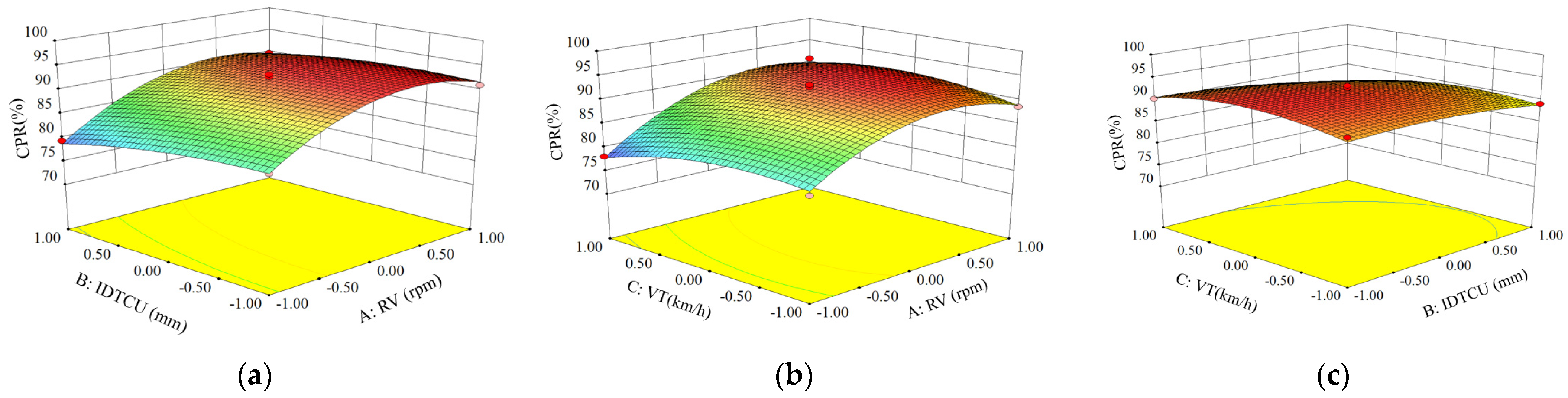
C: VT) had a significant effect on CPR. For the interaction effects, the interactive factor AC had a significant effect on CPR. The interactive factor AB, BC had no significant effect on CPR (Figure 13a,b). For the quadratic factor effect, the quadratic factor A2 had a highly significant effect on CPR. The quadratic factors B2 and C2 had a significant effect on CPR. Consequently, the regression models were optimized so that the insignificant items were removed, while ensuring p < 0.01 for the model and p > 0.05 for the lack of fit, as shown in Equation (15).
Y 1 = 92.48 + 4.70 A 1.71 B 0.84 C + 1.35 A C 5.35 A 2 1.18 B 2 2.43 C 2
The contribution value rate (K) reflects the influence degree of a single parameter on the regression model such that a higher value of K indicates a greater influence degree. K is calculated as follows:
δ = { 0 1 1 F F 1 F > 1
K X j = δ X j + 1 2 i = 1 3 δ X j δ X i + δ X j 2 j = 1 , 2 , 3 i j
where δ is the evaluation value of the regression term to F, F is each F value of the regression term in the regression equation in Table 4, and KXj is the contribution rate of each parameter.
From Table 4 and Equations (15)–(17), the order of the contribution rate of each parameter on CPR was the rotational velocities of the two chopping units (factor A: RV) > the installation distance of the two chopping units (factor B: IDTCU) > the velocity of the tractor (factor C: VT). The calculation results are shown in Table 5.
As shown in Table 3 and Table 4, when the values of factor B (IDTCU) and factor C (VT) are 600 mm (0) and 4 km/h (0), respectively, the CPR increased when the factor A (RV) increased from 550 (−1) rpm to 680 (0.3) rpm. The maximum value of the CPR could be obtained when factor A (RV) was around 680 rpm (0.3). The CPR decreased while factor A (RV) increased when the value of factor A (RV) was larger than 680 rpm (0.30). However, the decrease rate was slow. When the values of factor A (RV) and factor C (VT) are 650 rpm (0) and 4 km/h (0), respectively, the CPR increased when factor B (IDTCU) increased from 480 mm (−1) to 600 (0) mm. The maximum value of CPR could be obtained when factor B (IDTCU) was around 540 mm (−0.5). The CPR decreased while factor A (RV) increased from 540 rpm (−0.5) to 720 (1) mm. When the values of factor A (RV) and factor B (IDTCU) are 650 rpm (0) and 600 mm (0), respectively, the CPR increased when factor C (VT) increased from 3 (−1) km/h to 4 km/h (0). The maximum value of the CPR could be obtained when factor C (VT) was around 4 km/h (0). The CPR decreased while factor C (VT) increased from 4 km/h (0) to 5 km/h (1).
In terms of the above significance analysis, the law of influence of the interactive factors AC on the CPR was studied. The interaction of the rotational velocities of the two chopping units (factor A: RV) and the velocity of the tractor (factor C: VT) on the CPR are shown in Figure 13b. The effect of AC on CPR is the same regardless of the value of factor B. The CPR first increased and then decreased with an increase in the rotational velocities of the two chopping units at the same velocity as the tractor. The CPR will decrease when the rotational velocities of the two chopping units exceed a critical value. Besides, the CPR first increased and then decreased with an increase in the velocity of the tractor at the same rotational velocities of the two chopping units. The CPR will increase when the velocity of the tractor is increased within limits. When the velocity of the tractor exceeds the critical value, the CPR will decrease. Therefore, there was an optimal combination of the rotational velocities of the two chopping units and the velocity of the tractor that resulted in the maximum CPR. In summary, the maximum CPR can be obtained when the rotational velocities of the two chopping units are equal to 650 rpm, the installation distance of the two chopping units is equal to 600 mm, and the velocity of the tractor is equal to 4 km/h.
The quadratic polynomial regression model showing the effect of A (RV), B (IDTCU), and A (VT) on SBD (0–50 mm), SBD (50–100 m), and SBD (100–150 mm) was established based on the data in Table 6. The regression model is shown in Equations (18)–(20). The variance analysis of regression equations is shown in Table 7.
Y 2 = 0.93 0.086 A + 0.021 B + 0.040 C 0.013 A B 0.020 A C 0.020 B C + 0.033 A 2 + 0.028 B 2 + 0.021 C 2
Y 3 = 1.22 0.061 A 0.005 B + 0.044 C 0.020 A B 0.0025 A C 0.015 B C + 0.048 A 2 + 0.031 B 2 + 0.033 C 2
Y 4 = 1.45 + 0.011 A + 0.025 B 0.014 C 0.013 A B 0.015 A C 0.0075 B C + 0.0015 A 2 + 0.009 B 2 + 0.019 C 2
According to the analysis results in Table 7, the significance levels of the regression model for SBD (0–50 mm, 50–100 mm) were all less than 0.05, and the lack of fit for the model was greater than 0.05. Therefore, there was a significant relationship between three factors (A: RV, B: IDTCU, and C: VT) and SBD (0–50 mm, 50–100 mm). In addition, the coefficient of determination R2 of the equations were 0.9443 (0–50 mm) and 0.9365 (50–100 mm), demonstrating that more than 94% and 93% of the response values could be explained by the regression models. Therefore, the structural parameters and working parameters of the chopping device could be predicted and analyzed using the regression model of CPR. However, the significance levels of the regression model for SBD (100–150 mm) were all more than 0.05, implying that there was an insignificant relationship between three factors (A: RV, B: IDTCU, and C: VT) and SBD (100–150 mm). For the main effect, the rotational velocities of the two chopping units (factor A: RV) and the velocity of the tractor (factor C: VT) had significant effects on SBD (0–50 mm, 50–100 mm). For the quadratic factor effect, the quadratic factor A2 had a significant effect on SBD (0–50 mm, 50–100 mm).
The values of SBD were 1.18 g/cm3 (0–50 mm), 1.36 g/cm3 (50–100 mm), and 1.48 g/cm3 (100–150 mm), respectively, before the field test. As shown in Table 6 and Table 7, the values of SBD (0–50 mm and 50–100 mm) were obviously decreased after the device conducted chopping operations. However, the values of SBD (100–150 mm) did not change significantly. Furthermore, the minimum values of SBD (0–50 mm, 50–100 mm) were all obtained when the rotational velocities of the two chopping units were 750 rpm, the installation distance of the two chopping units was 600 mm, and the velocity of the tractor was 3 km/h. There was a positive relationship between factor A: RV and SBD (0–50 mm, 50–100 mm). Meanwhile, there was a negative relationship between factor C: VT and SBD (0–50 mm, 50–100 mm).

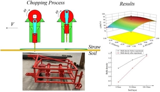
4.3. Effects on CPR and SBD

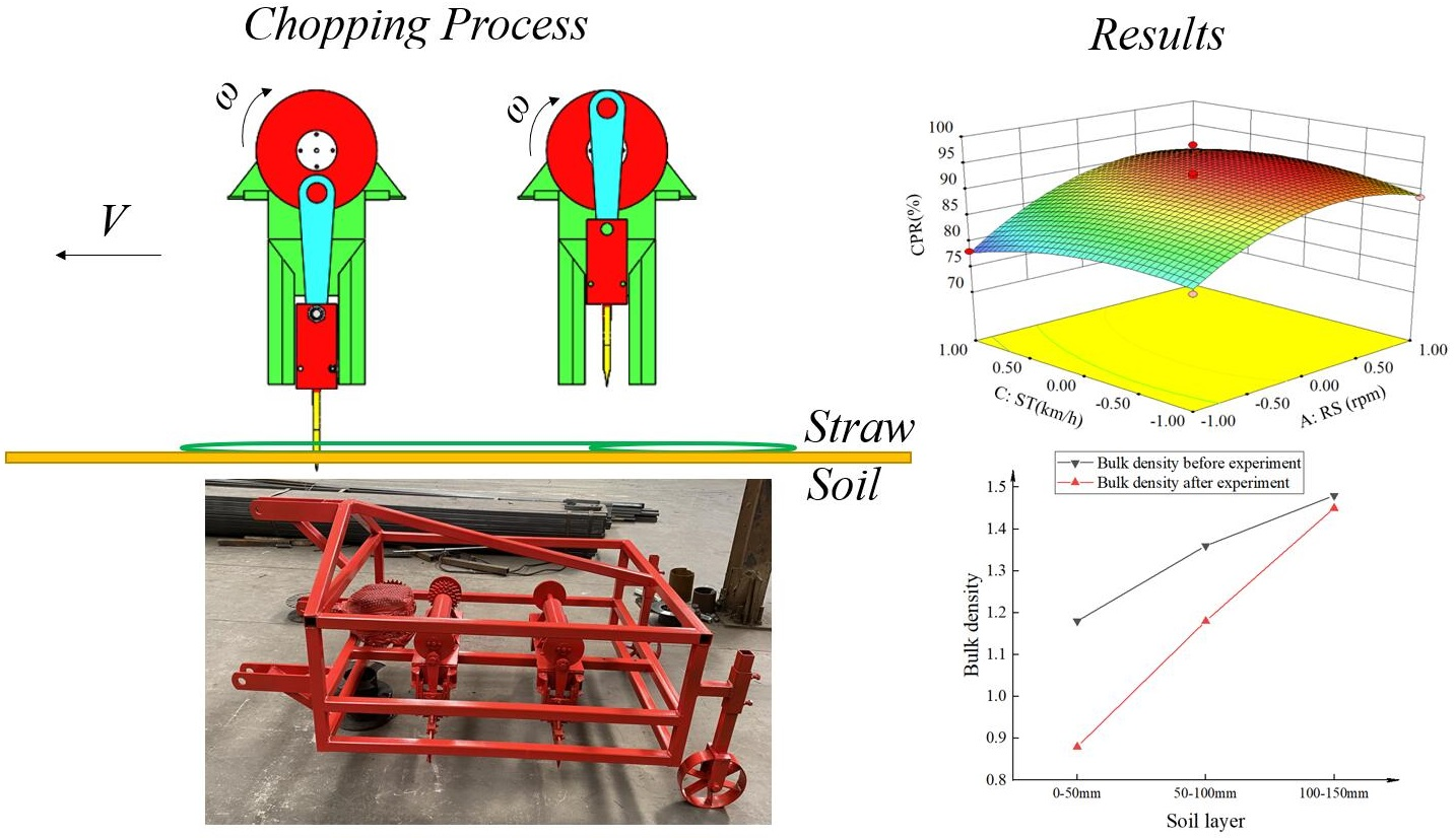
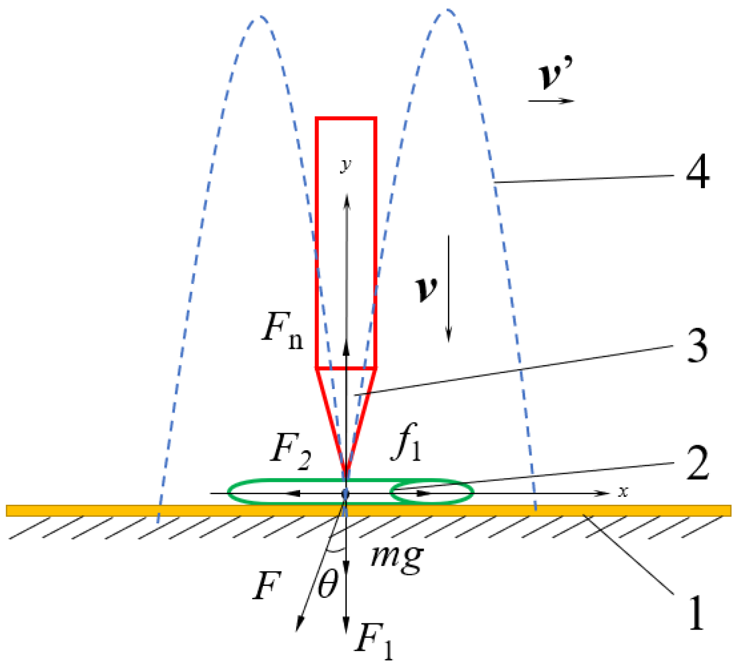
In the chopping process, under the ground support and chopping by the blades, the pith and rind are compressed; then, the rind is broken. With the high chopping velocity of the blade in the chopping process, the pith and rind are simultaneously chopped under a force, and the maize straw is finally cut off. When the velocity of the blade was increased, the chopping force on the straw from the chopping blade became larger. It makes the straw easier to be cut off, and then the CPR of maize straw is improved [41]. When the rotational velocities of the two chopping units are increased, the velocity and acceleration of the chopping blades are also increased. However, when the rotational velocities of the two chopping units are too fast, the chopping force will become so large that makes the straw move irregularly. There will be a leakage chopping phenomenon. When the velocity of the tractor is increased, the fluidity of straw will be also increased, which makes the straw be chopped easier. However, when the velocity of the tractor is too high, the chopping blade will drive the straw to move forward, and the straw will be piled up and then the device will be blocked.
In the chopping process, the soil is disturbed by chopping blades. With the high rotational velocity of the blades in the chopping process, the soil was loosed under force, and it finally became fined [18]. The depth of the chopping blade into the soil was 65.45 mm. Therefore, the soil was loose in the depth of 0 to 66 mm. The soil below 66 mm is not affected by the chopping blades. Therefore, the values of SBD (0–50 mm, 50–100 mm) were decreased sharply while the values of SBD (100–150 mm) did not change significantly. In this study, there was a positive correlation between factors A: RV and SBD (0–50 mm, 50–100 mm). The reason may be that in the maize straw chopping process when RV was increased, the force and frequency from the chopping blade are also increased. Simultaneously, there was a negative correlation between factors C: VT and SBD (0–50 mm, 50–100 mm). The reason may be that in the maize straw chopping process when VT was increased, the chopping times to soil is decreased per time.

4.4. Optimization and Verification

The analysis above indicates that the impact of various factors on the experimental index was inconsistent. To obtain the best value of CPR, and let the SBD (0–50 mm, 50–100 mm) decrease over 20% and 10%, respectively, a multi-objective optimization method combined with a restraint condition was used to optimize the regression equation. The restraint condition is given as:
max Y 1 ( R S D , I D T C U , S T ) Y 2 0.94 Y 3 1.22 s . t . { 550   rpm R S D 750   rpm 480   mm I D T C U 720   mm 3   km / h S T 5   km / h
Equation (21) was solved combined with restraint conditions, and the optimal parameter combination was as follows: the rotational velocity of the two chopping units was 610 rpm (−0.40), the installation distance of the two chopping units was 526.8 mm (−0.61), and the velocity of the tractor was 3.96 km/h (−0.04), while the CPR was 93.4%, the SBD values (0–50 mm, 50–100 mm, and 100–150 mm) were 0.90, 1.22, and 1.44, respectively.
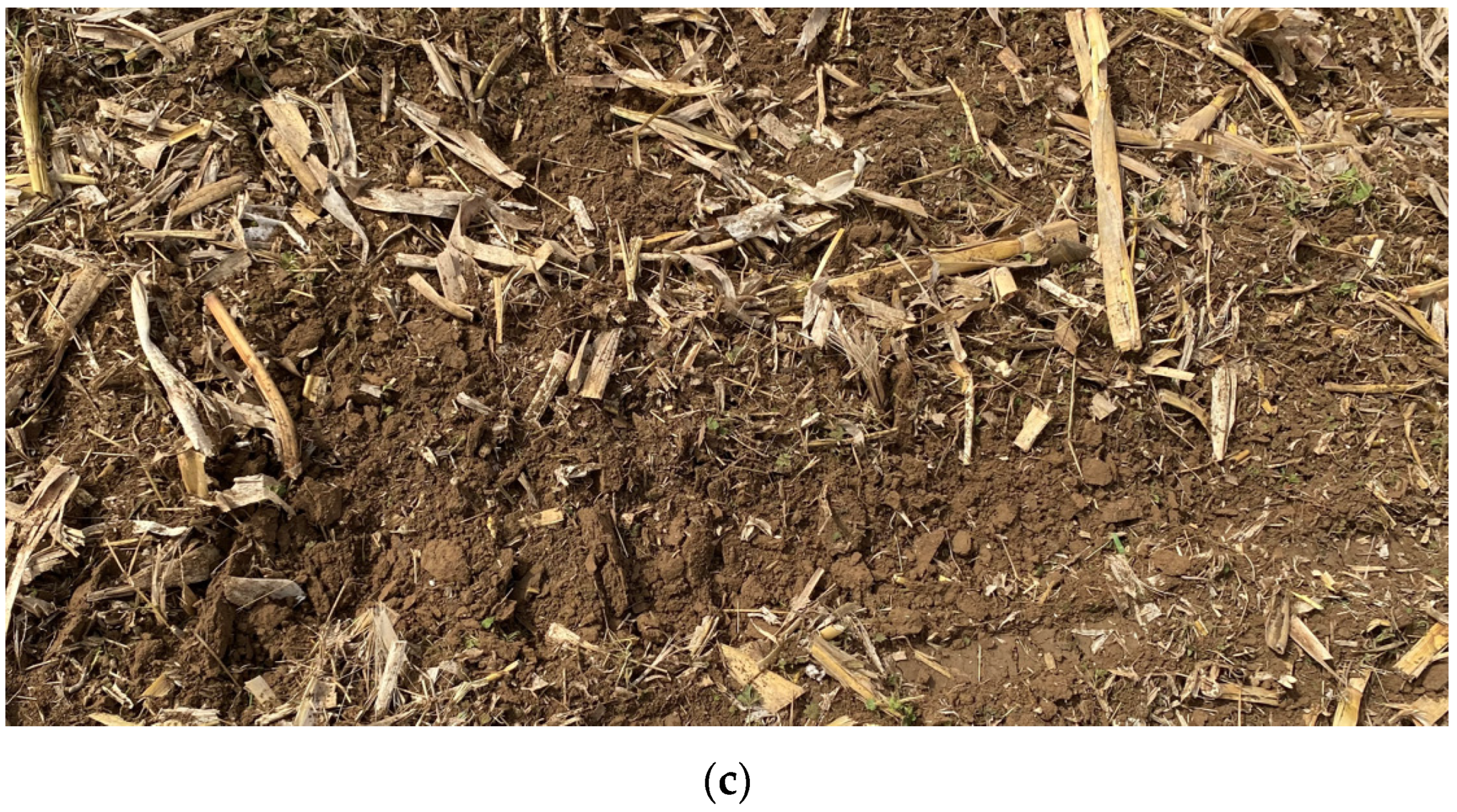
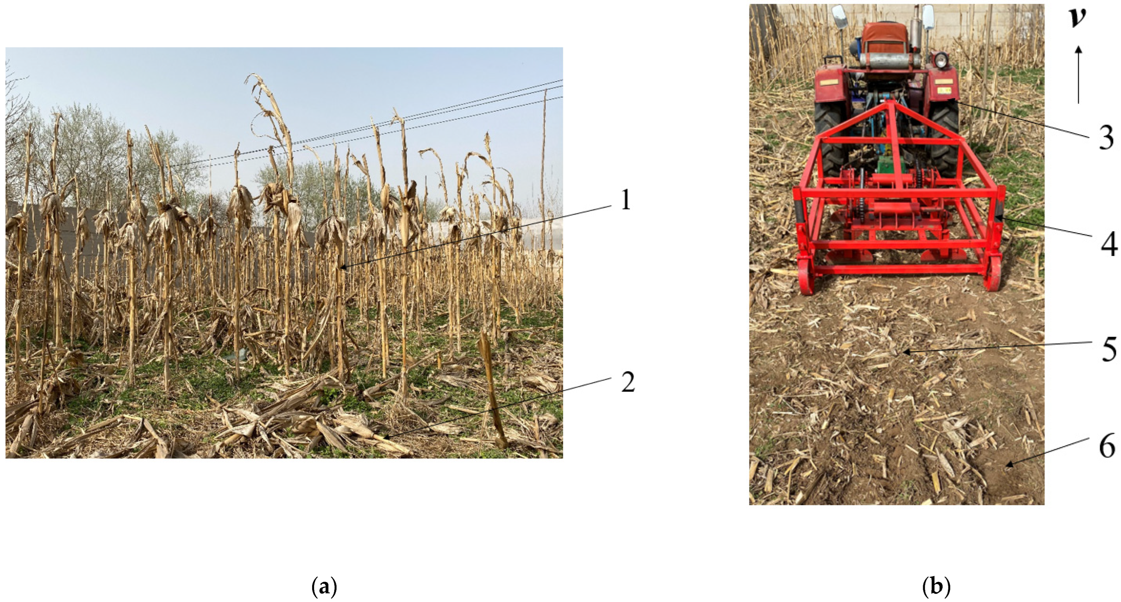
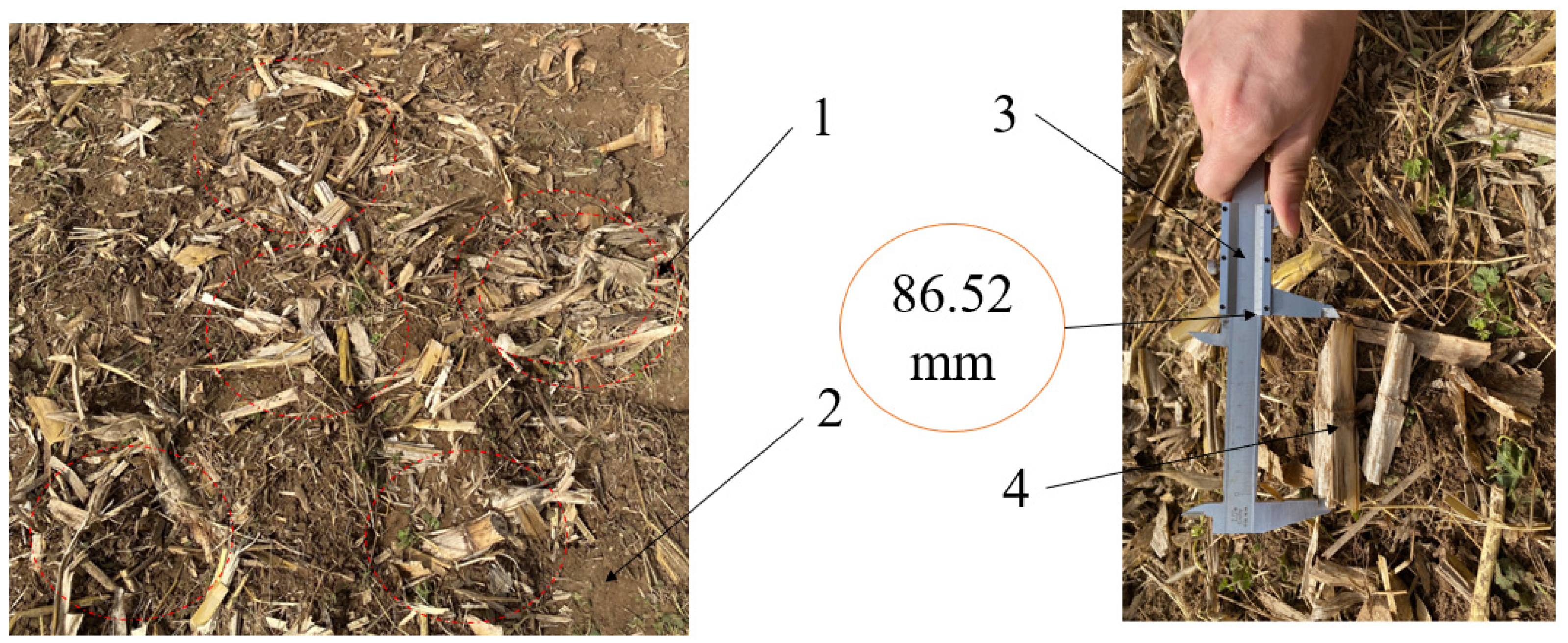
The field validation experiments were conducted to verify the reliability of the optimization results (Figure 14). The site selection and data collection were the same as described in 
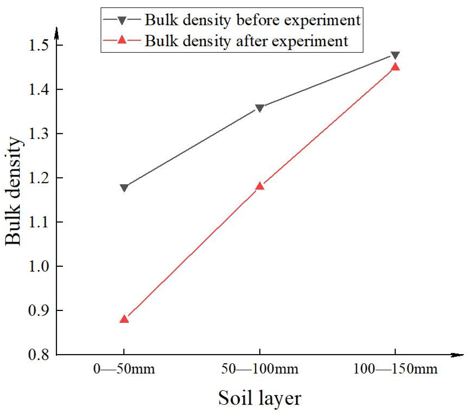
Section 3. The rotational velocities of the two chopping units were both 610 rpm, the installation distance of the two chopping units was 550 mm, and the velocity of the tractor was 4 km/h; these were selected as test factors. The results showed that the CPR was 92.0% and the difference was less than 5%. The SBD values (0–50 mm, 50–100 mm, and 100–150 mm) were 0.88, 1.18, and 1.45, respectively. In 0–50 mm and 50–100 mm soil layers, the bulk density was decreased 25.42% and 13.24%, respectively (Figure 15). Thus, the results of the study are considered acceptable.

5. Conclusions

The novel chopping device, based on the reciprocating intermittent motion mechanism, was developed to increase CPR for maize straw and decrease SBD after maize was harvested in China. In this study, the chopping principle of reciprocating intermittent motion mechanism and the force of straw during the chopping operation were theoretically analyzed. Furthermore, the structure and key parameters of the devices were optimized through dynamic and kinematics simulation analysis methods by ADAMS software. In addition, field experiments were conducted to explore the effects of rotational velocities of the two chopping units, the installation distance of the two chopping units, and the velocity of the tractor on CPR and SBD, and then, response surface analysis was applied to optimize the chopping device. Finally, field validation experiments were conducted to verify the reliability of the optimization results. The main conclusions were as follows:
(a)
Optimizing the structure and key parameters of the devices through dynamic and kinematics simulation analysis method by ADAMS software, it was determined that the rotation radius of the eccentric disc (a), the minimum transmission angle (γmin), the length of the link (b), the distance between O and B3 (L), the width of the track (w), and the depth of chopping blade into the soil (h1) were 75.00 mm, 75°, 289.78 mm, 204.91 mm, 32.91 mm, and 65.45 mm, respectively.
(b)
Via a response surface optimization experimental design and an analysis of CPR and SBD, the primary and secondary factors affecting the working performance of the chopping device were assessed. The optimal parameter combination was achieved: the rotational velocities of the two chopping units were both 610 rpm, the installation distance of the two chopping units was 526.8 mm, and the velocity of the tractor was 3.96 km/h. These values were determined by the regression model.
(c)
Finally, the working performances of the designed chopping device were verified through the field validation experiment. Under the velocity of 4 km/h, the CPR was 92.0% and the SBD values (0–50 mm, 50–100 mm, and 100–150 mm) were 0.88, 1.18, and 1.45, respectively. In general, the CPR of the device was much more superior to the relevant requirements as stipulated in the National Standards of China. Besides, the value of SBD (0–50 mm and 50–100 mm) decreased more than 20% and 10%, respectively, which can enhance seeding quality.
The designed chopping machine has the potential to make an important contribution to improving the chopping quality of maize straw in China. However, further research is needed on several aspects, including long-term experiments, energy consumption research, and device vibration research. Furthermore, in the future straw chopping machine and systems should be researched to further improve the CPR of maize straw.

Author Contributions

Conceptualization, H.L. (Han Lin) and J.H.; methodology, H.L. (Han Lin); P.L. and Y.C.; validation, H.L. (Han Lin) and Y.C.; software, W.Y.; writing—original draft preparation, H.L. (Han Lin); writing—review and editing, J.H.; H.L. (Hongwen Li), Q.W.; C.L. and S.H.; funding acquisition, H.L. (Hongwen Li) and J.H. All authors have read and agreed to the published version of the manuscript.

Funding

This research was funded by National Natural Science Foundation of China (Grant No. 31971803), the China Agriculture Research System of MOF and MARA (Grant No.CARS-03); Innovative Research Team in University of China (Grant No. IRT13039), and the 2115 Talent Development Program of China Agricultural University and Chinese Universities Scientific Fund (Grant No. 2021TC105).

Institutional Review Board Statement

Not applicable.

Informed Consent Statement

Not applicable.

Data Availability Statement

Not applicable.

Conflicts of Interest

The authors declare no conflict of interest.

References

  1. Liang, Y.; Al-Kaisi, M.; Yuan, J.; Liu, J.; Zhang, H.; Wang, L.; Cai, H.; Ren, J. Effect of chemical fertilizer and straw-derived organic amendments on continuous maize yield, soil carbon sequestration and soil quality in a Chinese Mollisol. Agric. Ecosyst. Environ. 2021, 314, 107403. [Google Scholar] [CrossRef]
  2. Zhang, Z.; Qiang, H.; McHugh, A.D.; He, J.; Li, H.; Wang, Q.; Lu, Z. Effect of conservation farming practices on soil organic matter and stratification in a mono-cropping system of Northern China. Soil Res. 2016, 156, 173–181. [Google Scholar] [CrossRef]
  3. Kretschmer, B.; Allen, B.; Hart, K. Mobilising Cereal Straw in the EU to Feed Advanced Biofuel Production. Report Produced for Novozymes; Institute for European Environmental Policy: London, UK, 2012. [Google Scholar]
  4. Scott, B.J.; Podmore, C.M.; Burns, H.M.; Bowden, P.I.; McMaster, C.L. Developments in Stubble Retention in Cropping Systems in Southern Australia; Nicholls, C., Wolfe, E.C., Eds.; Report to GRDC on Project DAN 00170; NSW Department of Primary Industries: Orange, Australia, 2013. [Google Scholar]
  5. Watts and Associates. Feasibility Research Report for Insuring Corn Stover, Straw and Other Crop Residues. Deliverable 2: Final Feasibility Report. Risk Management Agency. Contract No: D11PX18877. 2011. Available online: https://www.rma.usda.gov/-/media/RMA/Publications/Risk-Management-Publications/cornstover_straw_other.ashx?la=en (accessed on 29 December 2021).
  6. Hiloidhari, M.; Das, D.; Baruah, D.C. Bioenergy potential from crop residue biomass in India. Renew. Sustain. Energy Rev. 2014, 32, 504–512. [Google Scholar] [CrossRef]
  7. Sun, N.; Wang, X.; Li, H.; He, J.; Wang, Q.; Wang, J.; Liu, Z.; Wang, Y. Design and experiment of differential sawing rice straw chopper for turning to field. Trans. Chin. Soc. Agric. Eng. 2019, 35, 267–276. [Google Scholar] [CrossRef]
  8. Zhu, K.; Liu, Z.; Tan, X.; Lin, J.; Xu, D. Study on the ecological potential of Chinese straw resources available for bioenergy producing based on soil protection functions. Biomass Bioenergy 2018, 116, 26–38. [Google Scholar] [CrossRef]
  9. Li, Y.M.; Duan, Y.; Wang, G.L.; Wang, A.Q.; Shao, G.Z.; Meng, X.H.; Zhang, D.M. Straw alters the soil organic carbon composition and microbial community under different tillage practices in a meadow soil in Northeast China. Soil Res. 2021, 208, 104879. [Google Scholar] [CrossRef]
  10. Liu, P.; He, J.; Li, H.; Wang, Q.; Lu, C.; Zheng, K.; Liu, W.; Zhao, H.; Lou, S. Effect of straw retention on crop yield, soil properties, water use efficiency and greenhouse gas emission in China: A meta-analysis. Int. J. Plant Prod. 2019, 13, 347–367. [Google Scholar] [CrossRef]
  11. General Administration of Quality Supervision, Inspection and Quarantine of the People’s Republic of China; Standardization Administration. GB/T 24675.6-2009 Conservation Tillage Equipment—Smashed Straw Machine; China Standards Press: Beijing, China, 2010. [Google Scholar]
  12. Jia, H.; Jiang, X.; Guo, M.; Liu, X.; Wang, L. Design and experiment of V-L shaped smashed straw blade. Trans. Chin. Soc. Agric. Eng. 2015, 31, 28–33. [Google Scholar] [CrossRef]
  13. Zhang, Z.; He, J.; Li, H.; Wang, Q.; Ju, J.; Yan, X. Design and experiment on straw chopper cum spreader with adjustable spreading device. Trans. Chin. Soc. Agric. Mach. 2017, 48, 76–87. [Google Scholar] [CrossRef]
  14. Abilzhanov, D.; Abilzhanuly, T.; Golikov, V.; Adilsheyev, A.; Alshurina, A. Development of universal pick-up chopper for harvesting of chopped hay and haylage. J. Eng. Appl. Sci. 2017, 12, 3309–3314. [Google Scholar] [CrossRef]
  15. Liu, P.; He, J.; Li, Y.; Li, H.; Wang, Q.; Lu, C.; Zhang, Z.; Li, S. Design and experiment of double rollers maize stalk chopping device with different rotation speeds. Trans. Chin. Soc. Agric. Eng. 2020, 36, 69–79. [Google Scholar] [CrossRef]
  16. Liu, P.; He, J.; Lou, S.; Wang, Y.; Zhang, Z.; Lin, H. Design and experiment for dynamic supporting type maize straw chopping retention device with different rotation speeds of disc blade. Trans. Chin. Soc. Agric. Mach. 2021, 52, 41–50. [Google Scholar] [CrossRef]
  17. Zastempowski, M.; Bochat, A. Research issues in the process of cutting straw into pieces. Sustainability 2020, 12, 6167. [Google Scholar] [CrossRef]
  18. Wang, Q.; Liu, Z.; He, J.; Li, H.; Li, W.; He, J.; Yan, X. Design and experiment of chopping type maize straw returning machine. Trans. Chin. Soc. Agric. Eng. 2018, 34, 10–17. [Google Scholar] [CrossRef]
  19. Liu, P.; He, J.; Li, H.; Wang, Q.; Lu, C.; Lou, S.; Wang, Y.; Lin, H.; Li, H.; Zhang, Z. Effects of various edge-curve types and rotational speeds of disc blades on breaking force and energy consumption in the maize stalk chopping process. Am. Soc. Agric. Biol. Eng. 2021, 37, 951–965. [Google Scholar] [CrossRef]
  20. Zheng, Z.; He, J.; Li, H.; Diao, P.; Wang, Q.; Zhang, X. Design and experiment of straw-chopping device with chopping and fixed knife supported slide cutting. Trans. Chin. Soc. Agric. Mach. 2016, 47, 108–116. [Google Scholar]
  21. Wang, J.; Wang, X.; He, J.; Li, H.; Lu, C.; Liu, D. Design and experiment of rice straw chopping device for agitation sliding cutting and tearing. Trans. Chin. Soc. Agric. Mach. 2021, 52, 28–40. [Google Scholar]
  22. He, J. Study on the Soil Characteristics of Wheat Field under Various Tillage Practices and the Physiological Basis of Water Saving in Wide-Range Sowing of Wheat; Shandong Agricultural University: Zibo, China, 2020. [Google Scholar]
  23. Hernández, A.; Muñoyerro, A.; Urízar, M.; Amezua, E. Optimization based mathematical procedure for dimensional synthesis of slider-crank linkage. Mathematics 2021, 9, 1581. [Google Scholar] [CrossRef]
  24. Šarga, P.; Hroncová, D.; Rákay, R. The msc ADAMS/view and simulation of the crank rocker mechanism. Am. J. Mech. Eng. 2015, 3, 161–164. [Google Scholar] [CrossRef]
  25. Sun, H.; Chen, Z.; Ge, W. Theory of Machines and Mechanisms; Higher Education Press: Beijing, China, 2013; pp. 132–136. [Google Scholar]
  26. Sun, S.; Lv, N.; Xu, J.; Yan, Y.; Li, Z. A MATLAB realization method of connecting rod mechanism design according to the stroke speed ratio coefficient. Electron. Test 2021, 09, 57–58. [Google Scholar] [CrossRef]
  27. Guo, J.; Zheng, R.; Lv, H. AUV Underwater docking collision analysis and guidance structure optimization based on ADAMS simulation. Acta Armamentarii. 2019, 40, 1058–1067. [Google Scholar] [CrossRef]
  28. Li, H.; Wu, C.; Mu, S.; Guan, Z.; Jiang, T. Formation mechanism of laying angle of vertical rape windrower based on ANSYS-ADAMS. Trans. Chin. Soc. Agric. Eng. 2020, 36, 96–105. [Google Scholar] [CrossRef]
  29. Li, P.; Cui, J.; Feng, W.; Zhang, X.; Zhang, T.; Li, Y. Design and test of real-time monitoring system for feeding quantity of small combine. J. Agric. Mech. Res. 2022, 44, 240–246. [Google Scholar] [CrossRef]
  30. Wu, L.; Yang, Z.; Duan, J.; Wang, L.; Wang, W.; Liu, J.; Wang, L. Experiment on influencing factors of cutting force of blades of trim tool for longan branch. Trans. Chin. Soc. Agric. Eng. 2012, 28, 8–14. [Google Scholar]
  31. Gao, X. Experimental Study of Mechanical Properties of Corn Stalks; Huazhong Agricultural University: Wuhan, China, 2013. [Google Scholar] [CrossRef]
  32. Yuan, H.; Wang, D.; Wang, G.; Fu, Z.; Cai, S.; Liang, F. Design and experiment of straw cutting and rubbing process device. Trans. Chin. Soc. Agric. Mach. 2012, 43 (Supp. 1), 153–157. [Google Scholar] [CrossRef]
  33. Wu, L.; Yang, Z.; Li, H.; Wu, W. Experiment of mechanical properties of longan branch for pruning machine design. J. Hunan Agric. Univ. 2018, 044, 210–215. [Google Scholar] [CrossRef]
  34. Lai, R.; Sun, Y.; Jin, G. Experimental investigation of the cutting part for mini-type mulberry branch cutting machine. J. Agric. Mech. Res. 2013, 35, 150–153. [Google Scholar] [CrossRef]
  35. Xiang, J.; Yang, L.; Li, S. Experimental investigation of the base cutter for mini type sugarcane harvester. Trans. Chin. Soc. Agric. Eng. 2007, 23, 158–163. [Google Scholar]
  36. Chen, L.; Liang, X.; Cao, C. Virtual simulation and power test of straw counters-field based on multi-body dynamics. Trans. Chin. Soc. Agric. Mach. 2016, 47, 106–111. [Google Scholar] [CrossRef]
  37. Yan, X.; Zhou, L.; Jia, F. Compilation and verification of dynamic torque load spectrum of tractor power take-off. Trans. Chin. Soc. Agric. Eng. 2019, 35, 74–81. [Google Scholar] [CrossRef]
  38. Zheng, Z.; He, J.; Wang, Q.; Li, H.; Li, W.; Chen, W. Design and experiment on straw pickup-chopping and ditch-burying integrated machine. Trans. Chin. Soc. Agric. Mach. 2017, 48, 87–96. [Google Scholar] [CrossRef]
  39. He, J.; Li, H.; Rasaily, R.; Wang, Q.; Cai, G.; Su, Y.; Qiao, X.; Liu, L. Soil properties and crop yields after 11 years of no tillage farming in wheat–maize cropping system in North China Plain. Soil Res. 2011, 113, 48–54. [Google Scholar] [CrossRef]
  40. Wang, Q.; Lu, C.; Li, H.; He, J.; Sarker, K.; Rasaily, R.; Liang, Z.; Qiao, X.; Li, H.; Mchugh, A. The effects of no-tillage with subsoiling on soil properties and maize yield: 12-Year experiment on alkaline soils of Northeast China. Soil Res. 2014, 137, 43–49. [Google Scholar] [CrossRef]
  41. Song, Z.; Song, H.; Geng, A.; Li, Y.; Yan, Y.; Li, F. Experiment on Cutting Characteristics of Cotton Stalk With Double Supports. Trans. Chin. Soc. Agric. Eng. 2019, 31, 37–45. [Google Scholar] [CrossRef]
Figure 1. Structure of the chopping device. (a) The overall structure of the chopping device and the four chopping units. (b) Diagram of the chopping device. Note: (1) suspension unit, (2) gearbox, (3) four chopping units, (4) frame, (5) wheel, (6) the front left chopping unit, (7) the rear left chopping unit, (8) the rear right chopping unit, and (9) the front right chopping unit.
Agriculture 12 00220 g001
Figure 2. Working principle of the chopping machine. Note: (1) ground, (2) straw, (3) chopping unit, and (4) frame. V is the velocity of the tractor (km/h), fa is the frequency of the front chopping unit (Hz), l1 is the length of the straw chopped by the front chopping unit (mm), fb is the frequency of the rear chopping unit (Hz), and l2 is the length of the straw chopped by the rear chopping unit (mm).
Agriculture 12 00220 g002
Figure 3. Structure of the reciprocating intermittent mechanism. (a) The overall reciprocating intermittent mechanism, (b) the structure of the slider, and (c) the structure of the supporting sleeve. Note: (1) eccentric disc (crank), (2) link, (3) slider, (4) chopping blade, (5) supporting sleeve, (6) pulley (bearing), and (7) orbit.
Agriculture 12 00220 g003
Figure 4. The position of the chopping blade. Note: (1) ground, (2) chopping blade, (3) slider, (4) link, and (5) eccentric disc (crank). ω is the angular velocity of the eccentric disc (rad/s).
Agriculture 12 00220 g004
Figure 5. The movement diagram of the reciprocating intermittent mechanism. ω is the angular velocity of the eccentric disc (rad/s). A1B1, A2B2, A3B3, A4B4, are the four different positions of crank and link.
Agriculture 12 00220 g005
Figure 6. The schematic diagram of the key parameters. ω is the angular velocity of the eccentric disc (rad/s). A1B1, A2B2, A3B3, A4B4, are the four different positions of crank and link.
Agriculture 12 00220 g006
Figure 7. Model of the reciprocating intermittent mechanism. Note: (1) frame, (2) eccentric disc (crank), (3) link, (4) slider, (5) chopping blade, (6) straw, (7) rotation direction, and (8) forward direction.
Agriculture 12 00220 g007
Figure 8. Schematic diagram of the reciprocating intermittent mechanism. (a) A random position of the reciprocating intermittent mechanism, and (b) the highest/lowest position of the reciprocating intermittent mechanism. Note: (1) eccentric disc (crank), (2) link, and (3) slider. xoy is coordinate system. vr is the velocity of the slider on random position. ar is the acceleration of the slider on random position. amax is the maximum value of the acceleration of the slider.
Agriculture 12 00220 g008
Figure 9. Effect of the value of γmin on velocity.
Agriculture 12 00220 g009
Figure 10. Effect of the value of γmin on acceleration.
Agriculture 12 00220 g010
Figure 11. Stress diagram of maize straw in the chopping process. Note: (1) ground, (2) straw, (3) chopping blade, and (4) movement trajectory of the chopping blade.
Agriculture 12 00220 g011
Figure 12. Experiment field covered with maize straw. (a) Field straw, (b) the field experiments, and (c) the soil and straw after operation. Note: (1) upright straw, (2) field covered with maize straw, (3) the YTO-Dongfanghong-504 tractor, (4) the chopping device, (5) maize straw, and (6) ground.
Agriculture 12 00220 g012aAgriculture 12 00220 g012b
Figure 13. Analysis of double factors interaction on stalk chopping pass rate: (a) factor AB, (b) factor AC, and (c) factor BC.
Agriculture 12 00220 g013

SourceSum of SquaresDegree of FreedomMean SquareF Valuep-Value
Model380.65942.2944.52<0.0001 **
A–RV176.721176.72186.01<0.0001 **
B–IDTCU23.46123.4624.690.0016 *
C–VT5.6115.615.910.0454 *
AB2.2512.252.370.1677
AC7.2917.297.670.0277 *
BC2.7212.722.870.1343
A2120.631120.63126.97<0.0001 **
B25.8415.846.140.0423 *
C224.81124.8126.120.0014 *
Residual6.6570.95//
Lack of fit4.2631.422.380.2105
Pure error2.3940.60//
Total387.3016///

NumberTest FactorsSBD (g/cm3)
ABC0–50 mm Y250–100 mm Y3100–150 mm Y4
1650720511.291.46
255072041.111.41.46
375060050.941.31.49
465060040.931.191.46
575060030.861.191.47
6650720311.261.52
775048040.891.231.44
865060040.91.221.44
965060040.911.21.45
1065072050.991.331.41
1175060040.91.221.45
1265060040.951.231.47
1355048030.981.291.47
1465060040.941.241.42
1555072051.141.411.43
1655060041.051.331.4
1765048030.911.241.44

NumberTest FactorsCPR (%) Y1
ABC
1650720584.6
2550720479.4
3750600590.9
4650600492.6
5750600391.9
6650720392.1
7750480493.5
8650600491.7
9650600492.9
10650720589.2
11750600490.1
12650600493.1
13550480381.4
14650600492.9
15550720578.1
16550600483.7
17650480392.7

Code NumberA: RV (rpm)B: IDTCU (mm)C: VT (km/h)
−15504803
06506004
17507205
Figure 14. The field validation experiments Note: (1) straw, (2) ground, (3) Vernier caliper, and (4) single straw.
Agriculture 12 00220 g014
Figure 15. Results of SBD.
Agriculture 12 00220 g015
Table 1. The value of γmin, b, L, w, and h1 when the minimum transmission angle (γmin) takes different values.
Minimum Transmission Angle γmin/(°)b/mmL/mmw/mmh1/mm
73256.52170.3137.3664.26
75289.78204.9132.9165.45
77333.41249.8628.4866.67
79393.06310.8424.0767.91
Table 2. The experiment factors and levels.
Code NumberA: RV (rpm)B: IDTCU (mm)C: VT (km/h)
−15504803
06506004
17507205
Table 3. Experiment design and results.
NumberTest FactorsCPR (%) Y1
ABC
1650720584.6
2550720479.4
3750600590.9
4650600492.6
5750600391.9
6650720392.1
7750480493.5
8650600491.7
9650600492.9
10650720589.2
11750600490.1
12650600493.1
13550480381.4
14650600492.9
15550720578.1
16550600483.7
17650480392.7
Table 4. Experiment design and results.
NumberTest FactorsSBD (g/cm3)
ABC0–50 mm Y250–100 mm Y3100–150 mm Y4
1650720511.291.46
255072041.111.41.46
375060050.941.31.49
465060040.931.191.46
575060030.861.191.47
6650720311.261.52
775048040.891.231.44
865060040.91.221.44
965060040.911.21.45
1065072050.991.331.41
1175060040.91.221.45
1265060040.951.231.47
1355048030.981.291.47
1465060040.941.241.42
1555072051.141.411.43
1655060041.051.331.4
1765048030.911.241.44
factor A: RV, factor B: IDTCU, factor C: VT.
Table 5. Variance analysis for CPR.
SourceSum of SquaresDegree of FreedomMean SquareF Valuep-Value
Model380.65942.2944.52<0.0001 **
A-RV176.721176.72186.01<0.0001 **
B-IDTCU23.46123.4624.690.0016 *
C-VT5.6115.615.910.0454 *
AB2.2512.252.370.1677
AC7.2917.297.670.0277 *
BC2.7212.722.870.1343
A2120.631120.63126.97<0.0001 **
B25.8415.846.140.0423 *
C224.81124.8126.120.0014 *
Residual6.6570.95//
Lack of fit4.2631.422.380.2105
Pure error2.3940.60//
Total387.3016///
Note: ** was very significant (p < 0.01), * was significant (0.01 < p < 0.05), the others were insignificant.
Table 6. Importance of effects of factors on response functions.
IndexFactors Contribution Rate (K)Sort Contribution Rate
A: RVB: IDTCUC: VT
Y13.762.672.60A > B > C
Table 7. Variance analysis for SBD (0–50 mm, 50–100 mm, 100–150 mm).
SourceY2Y3Y4
Sum of SquaresFreedomMean SquareFpSum of SquaresFreedomMean SquareFpSum of SquaresFreedomMean SquareFp
Model0.09190.01013.200.0013 *0.06990.007611.480.0020 *0.01190.00123.220.0686
A0.06010.06077.94<0.0001 **0.03010.03045.230.0003 *0.00110.0012.670.1463
B0.003610.00364.730.06610.000210.00020.300.60010.00510.00513.180.0084
C0.01310.01316.760.0046 *0.01510.01523.080.0020 *0.001510.00153.990.0860
AB0.000610.00060.820.39570.001610.00162.410.16440.000910.00091.650.2401
AC0.001610.00162.100.19100.0000310.000030.0380.85160.000910.00092.370.1674
BC0.001610.00162.100.19100.000910.00091.360.28230.000210.00020.590.4664
A20.004710.00476.100.0429 *0.009810.009814.770.0063 *0.0000910.000090.0250.8789
B20.003410.00344.400.07410.004010.00406.000.0441 *0.000310.00030.900.3746
C20.001810.00182.370.16730.004610.00467.020.0330 *0.001410.00143.800.0923
Residual0.005370.0008//0.004670.0007//0.002770.0004//
Lack of fit0.003630.00122.810.17190.002930.0012.270.22270.001130.00041.060.4594
Pure error0.001740.0004//0.001740.0004//0.001540.0004//
Total0.09616///0.07316///0.01416///
Note: ** was very significant (p < 0.01), * was significant (0.01 < p < 0.05), and the others were insignificant.
Publisher’s Note: MDPI stays neutral with regard to jurisdictional claims in published maps and institutional affiliations.

