

Design of a Machine Vision-Based Automatic Digging Depth Control System for Garlic Combine Harvester


 and
and
Abstract
:1. Introduction
2. Materials and Methods
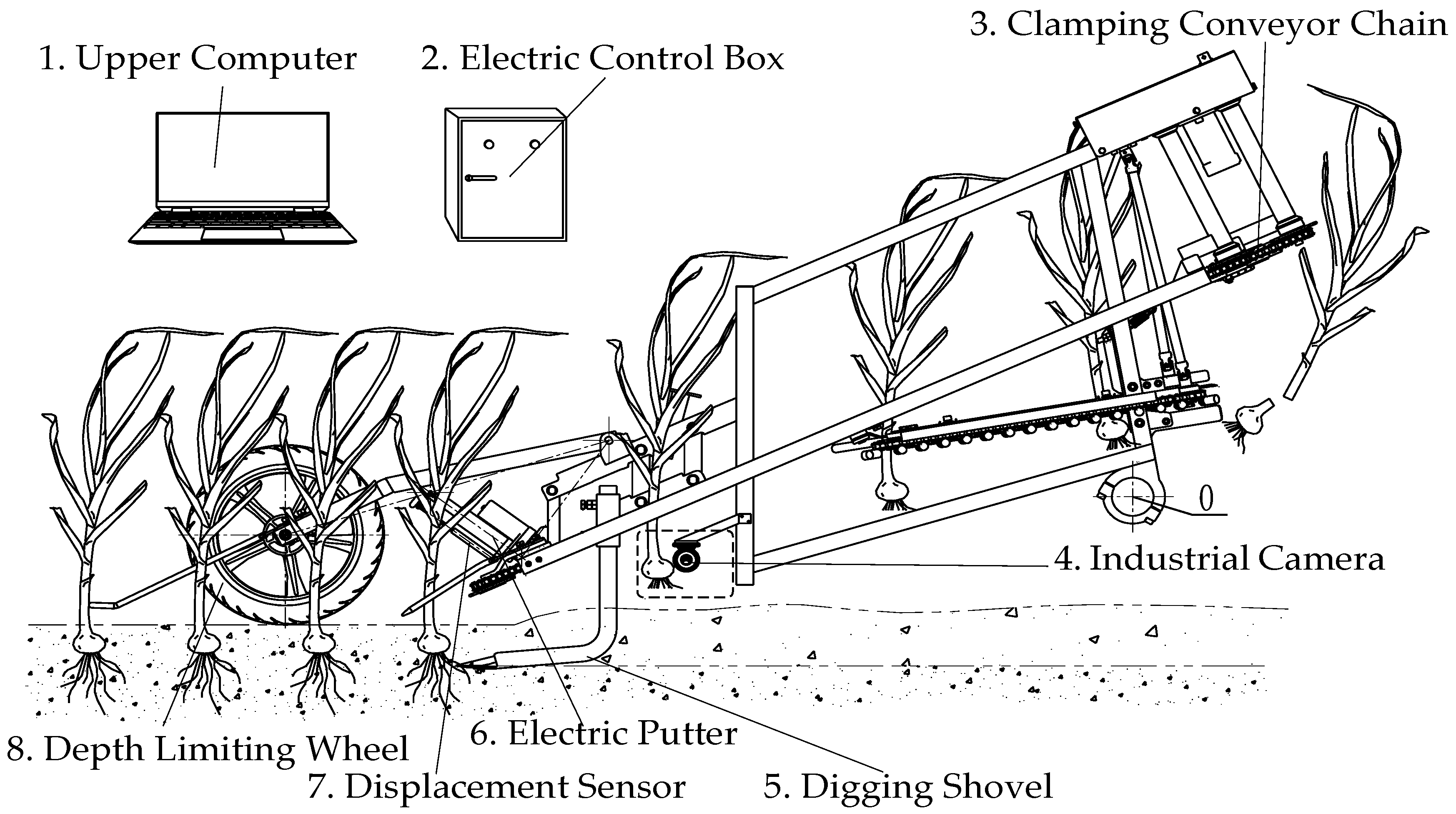
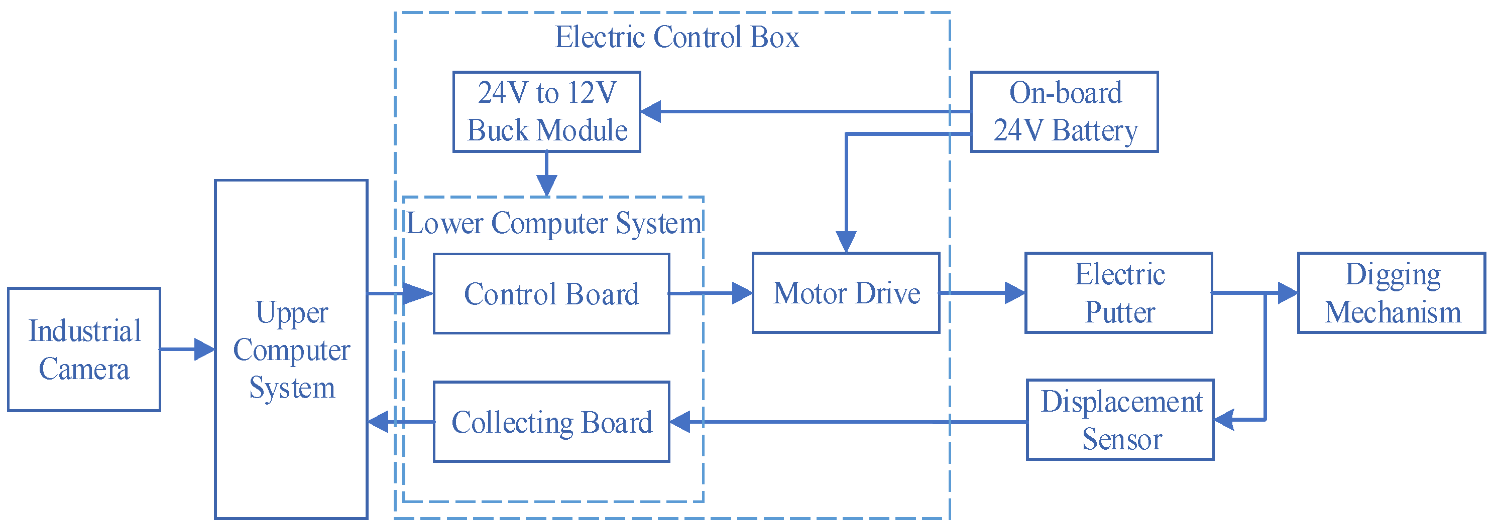
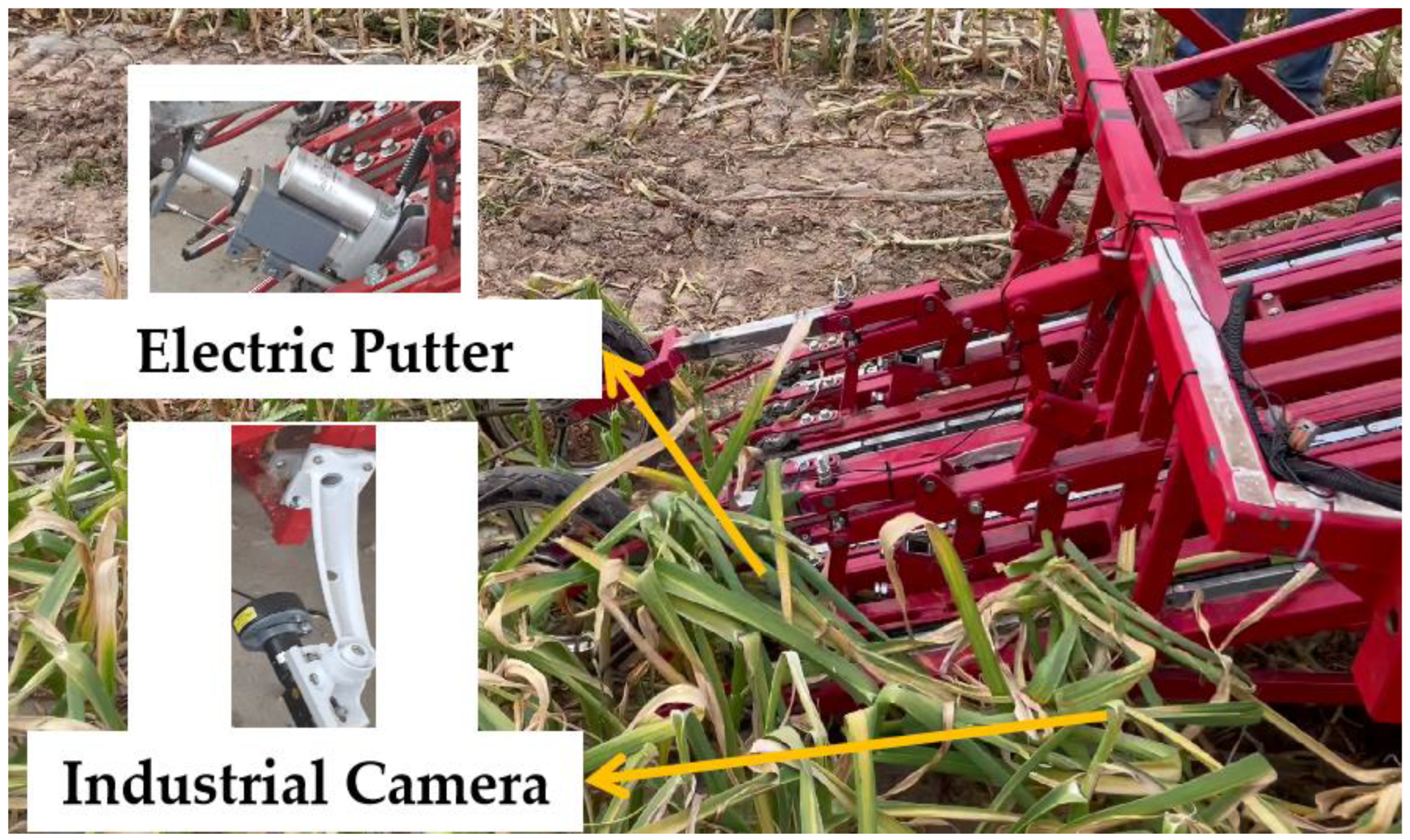
2.1. Overall System Structure and Working Principle
2.2. Main Material Selection
2.2.1. Industrial Camera
2.2.2. Microcontroller
2.2.3. Electric Putter
2.2.4. Displacement Sensor
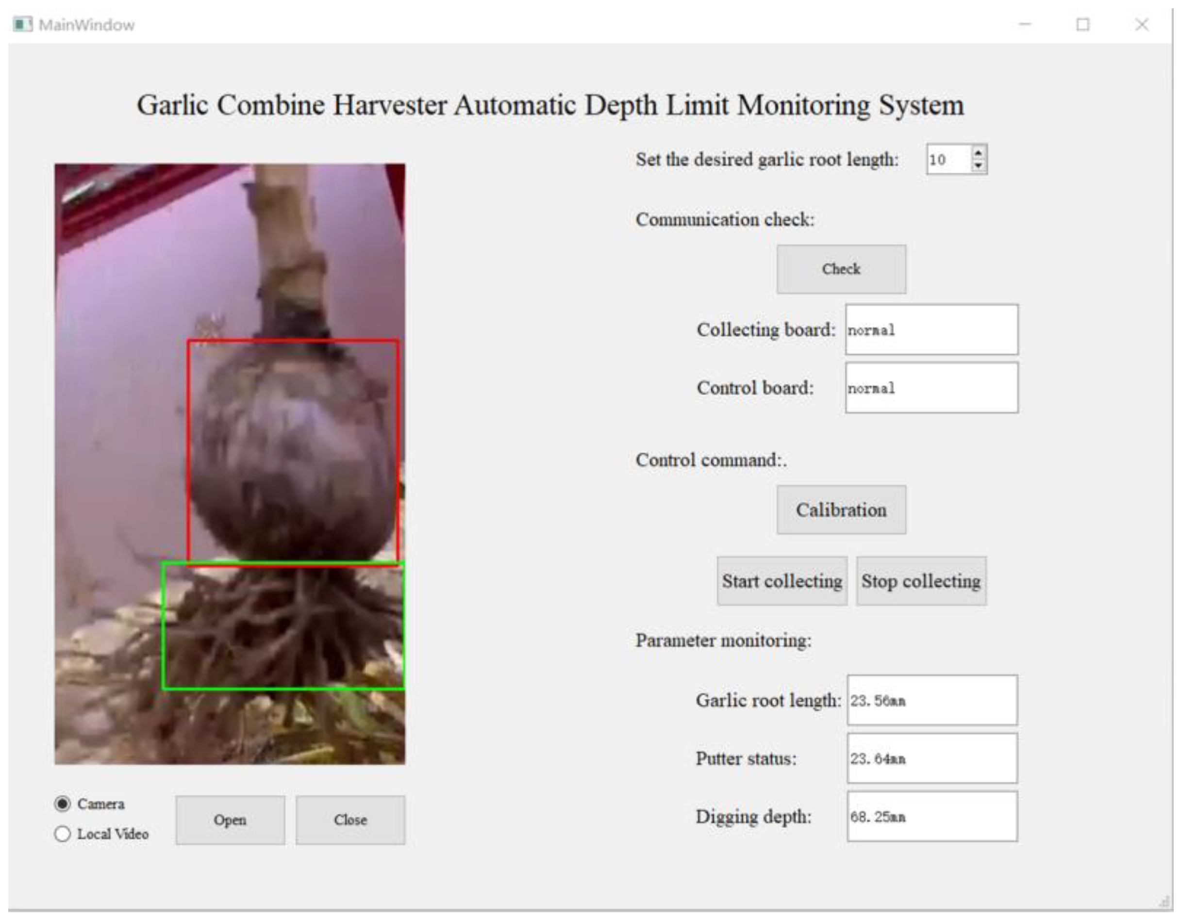
2.3. Software System Design
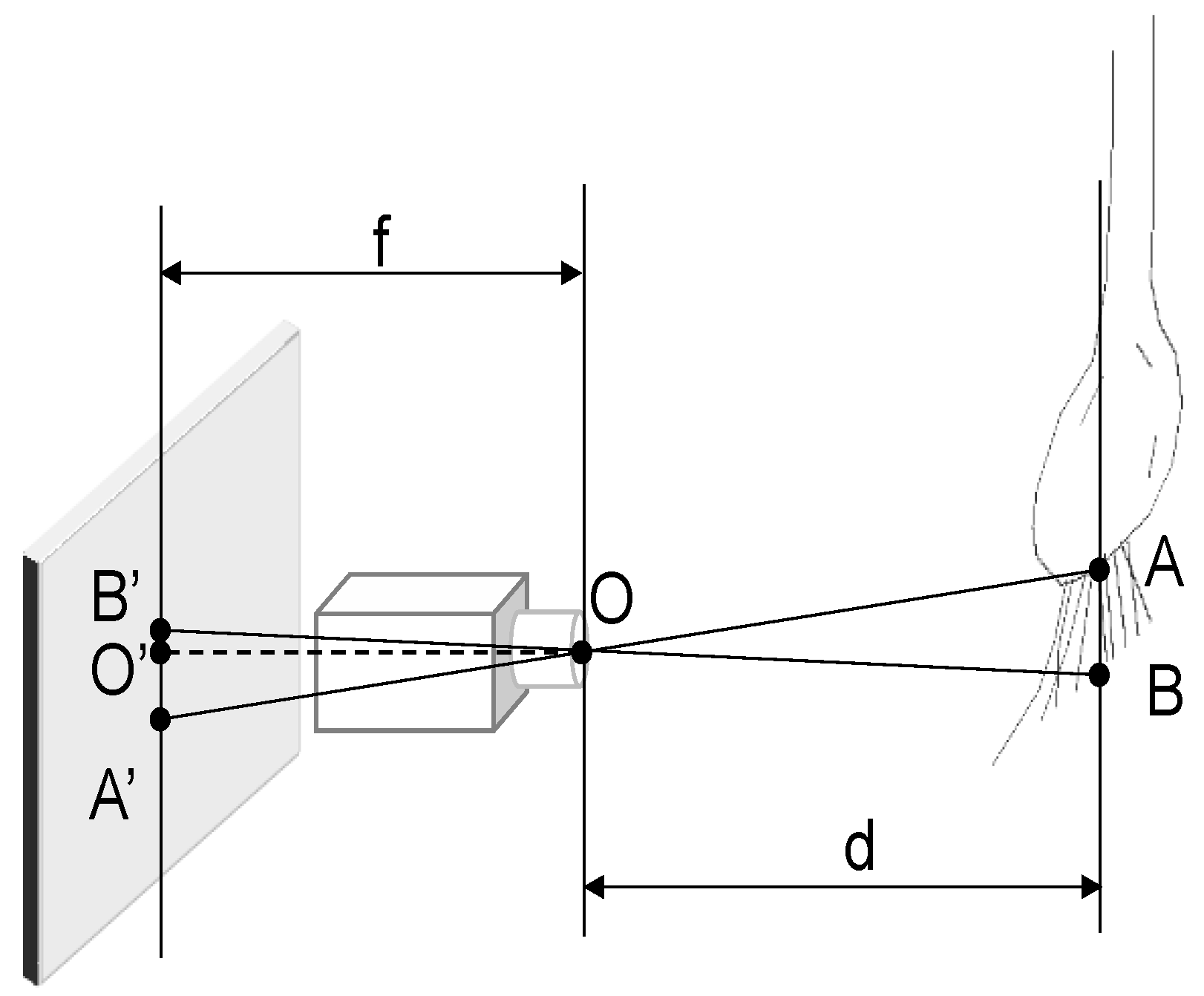
2.3.1. Machine Vision Measurement Principle
2.3.2. Camera Calibration
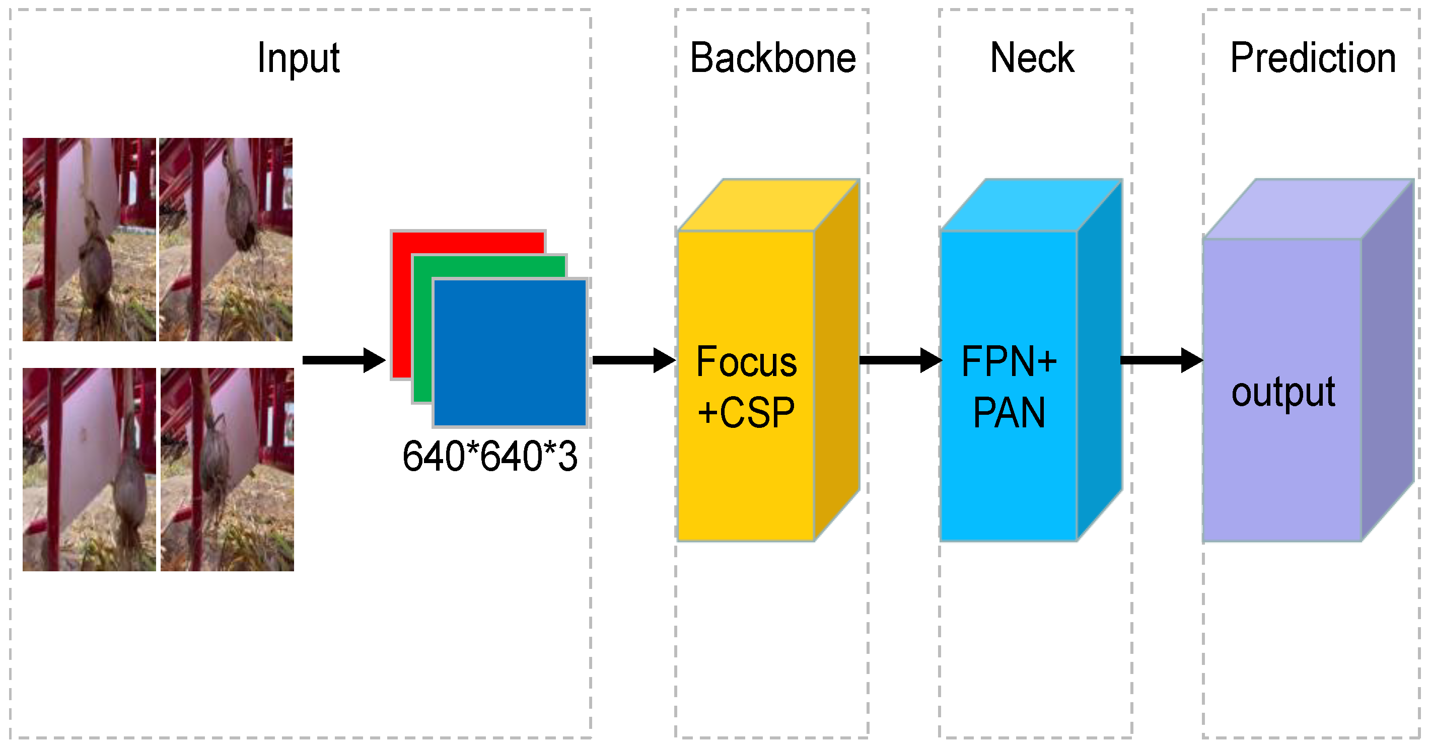
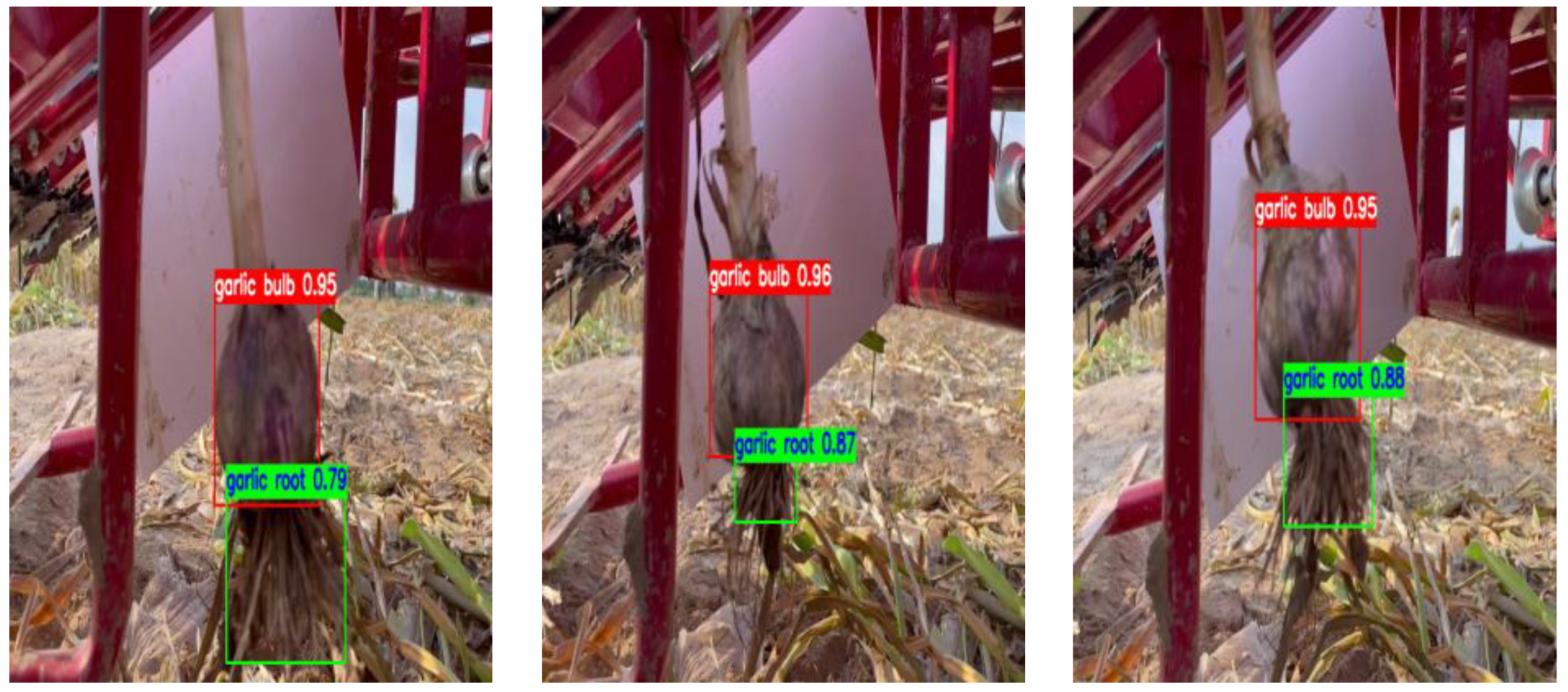
2.3.3. Target Detection
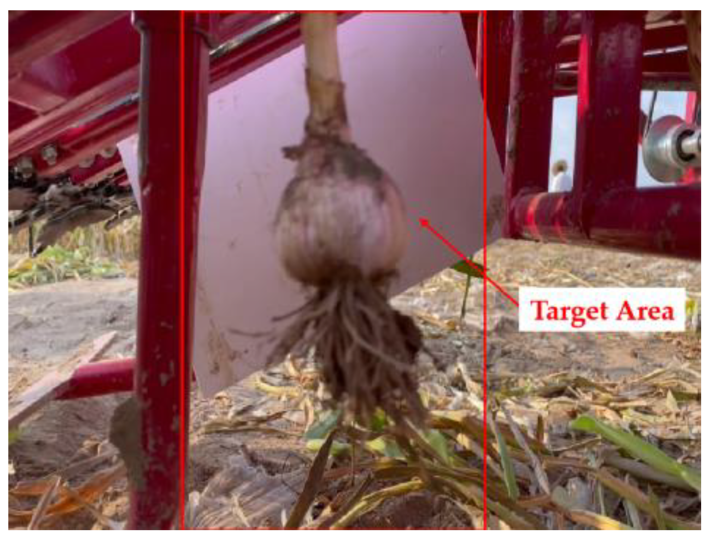
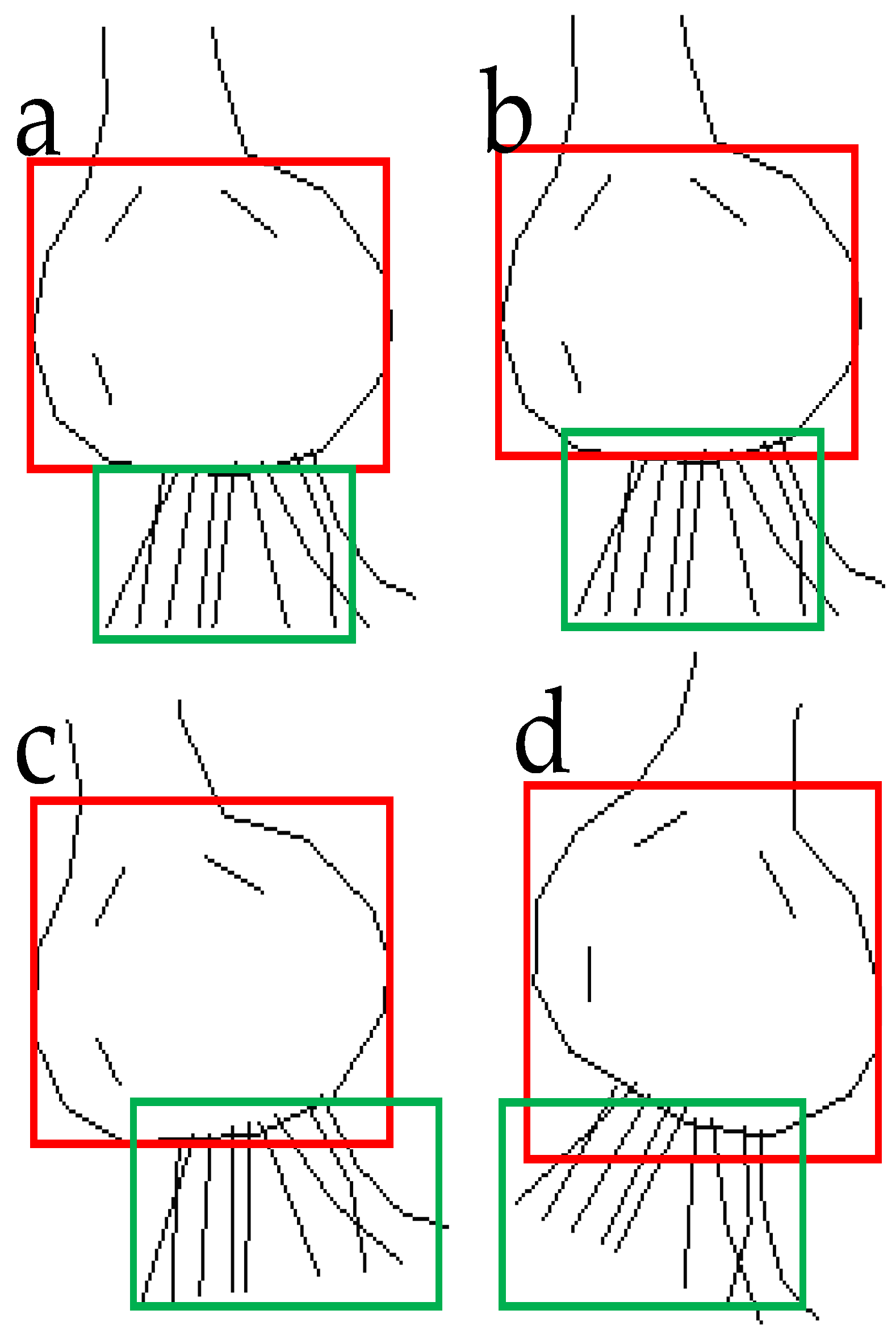
2.3.4. Calculation of Garlic Root Length
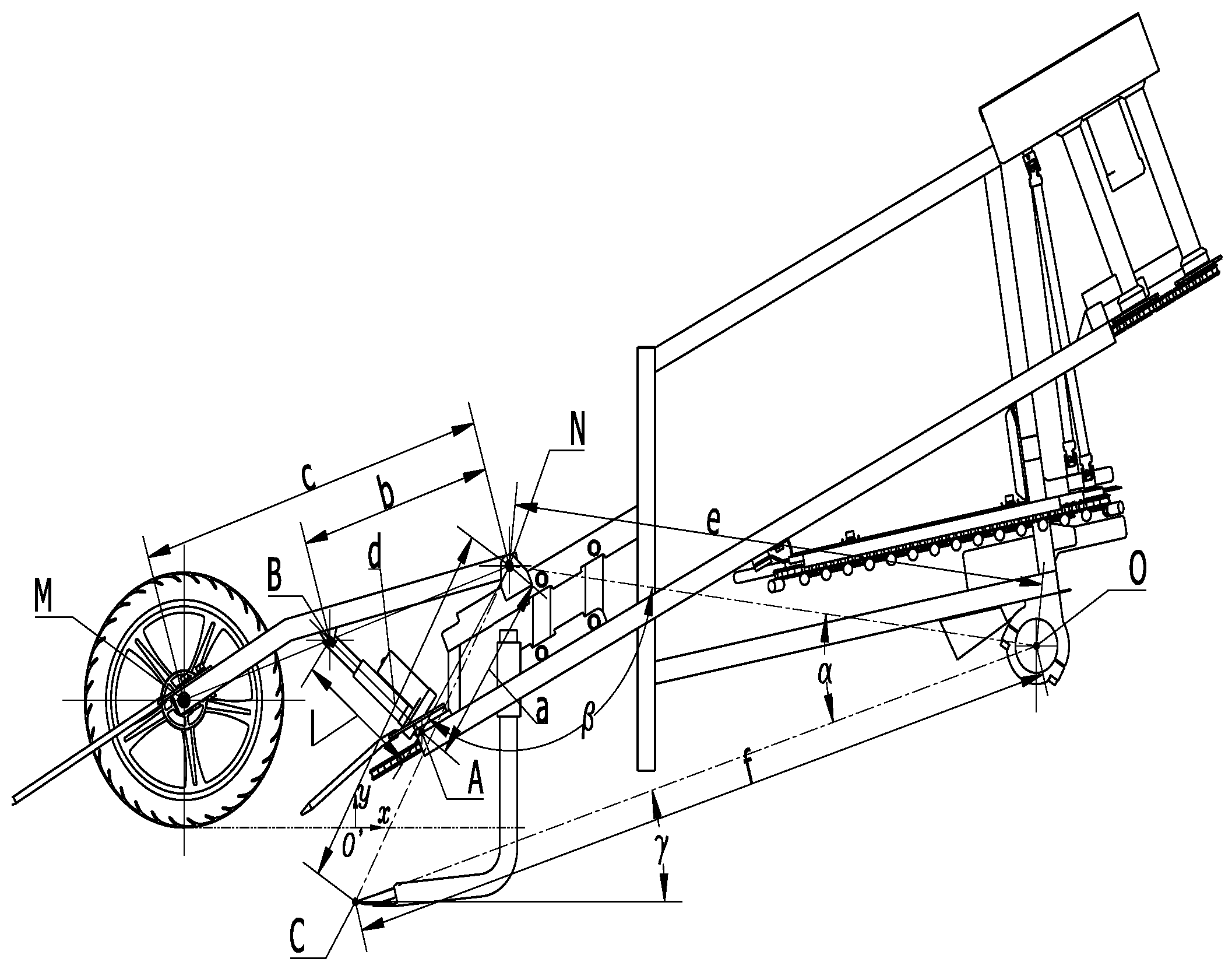
2.4. Control System Analysis and Design
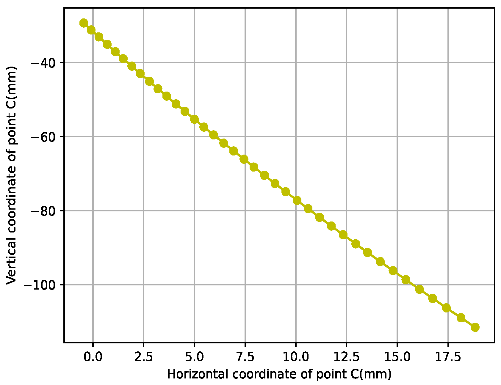
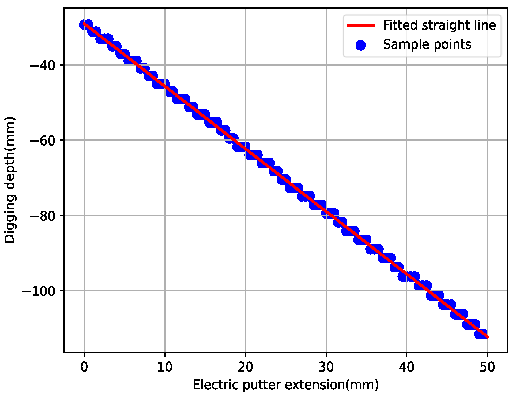
2.4.1. System Analysis
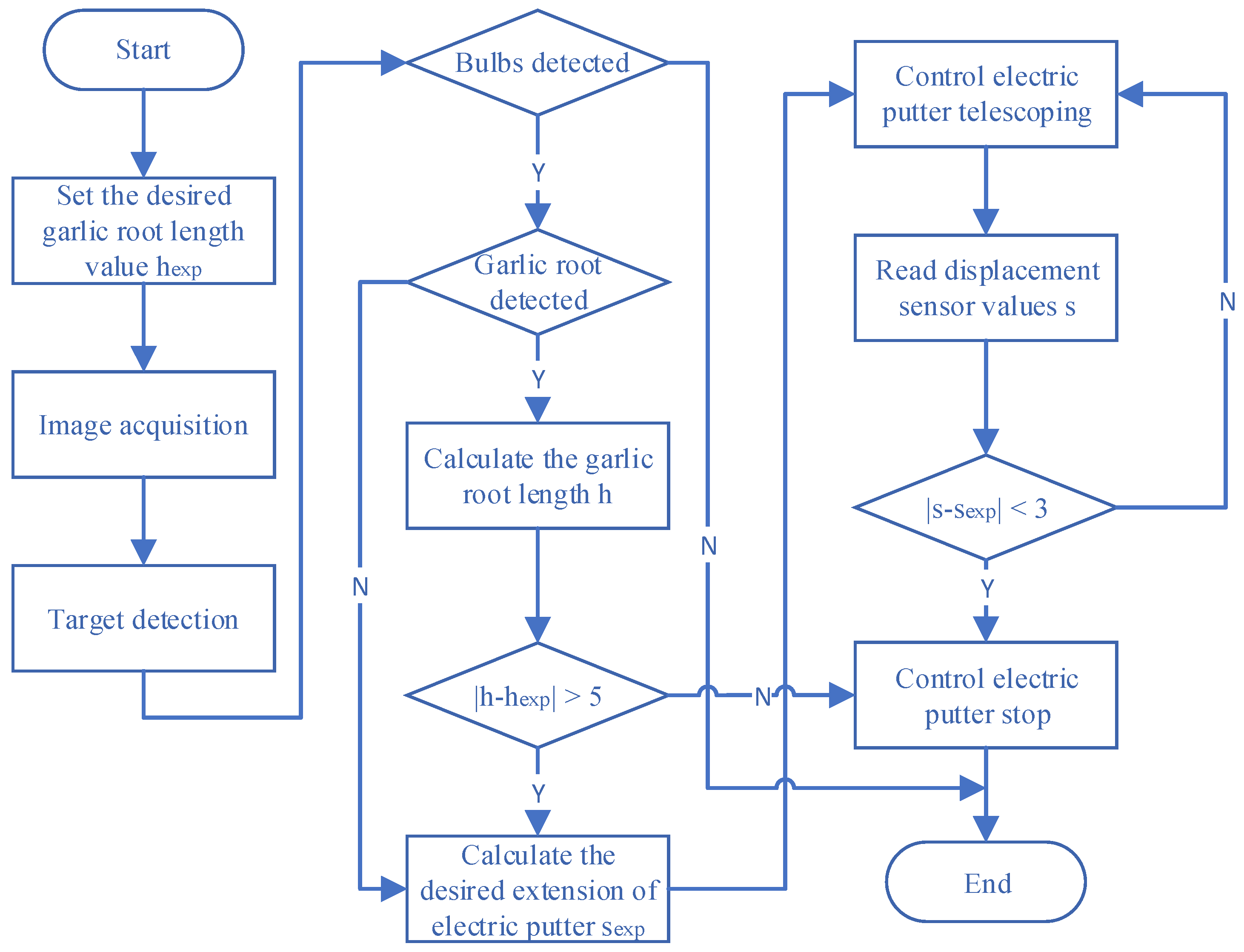
2.4.2. System Design
3. Results
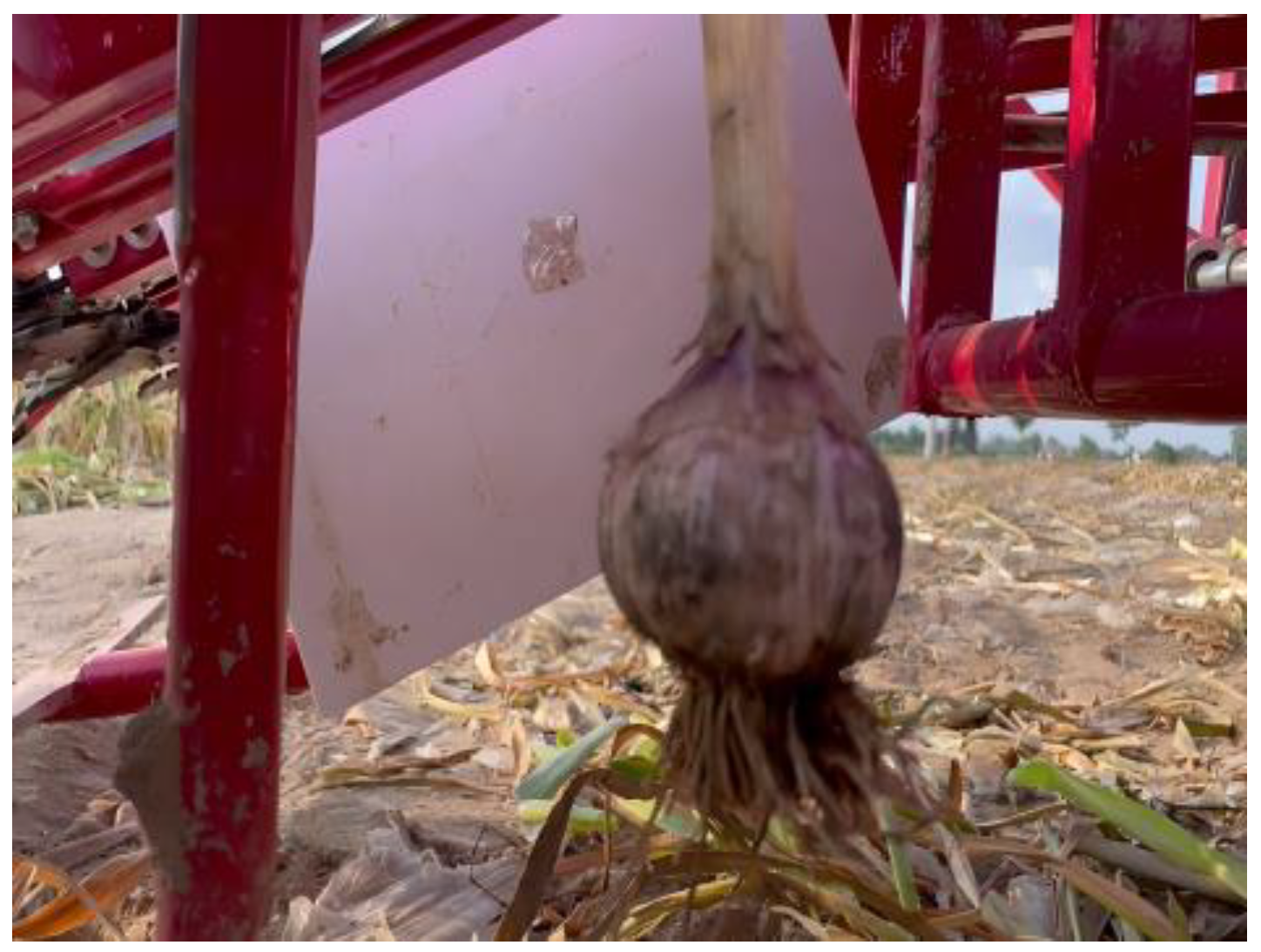
3.1. Test Platform
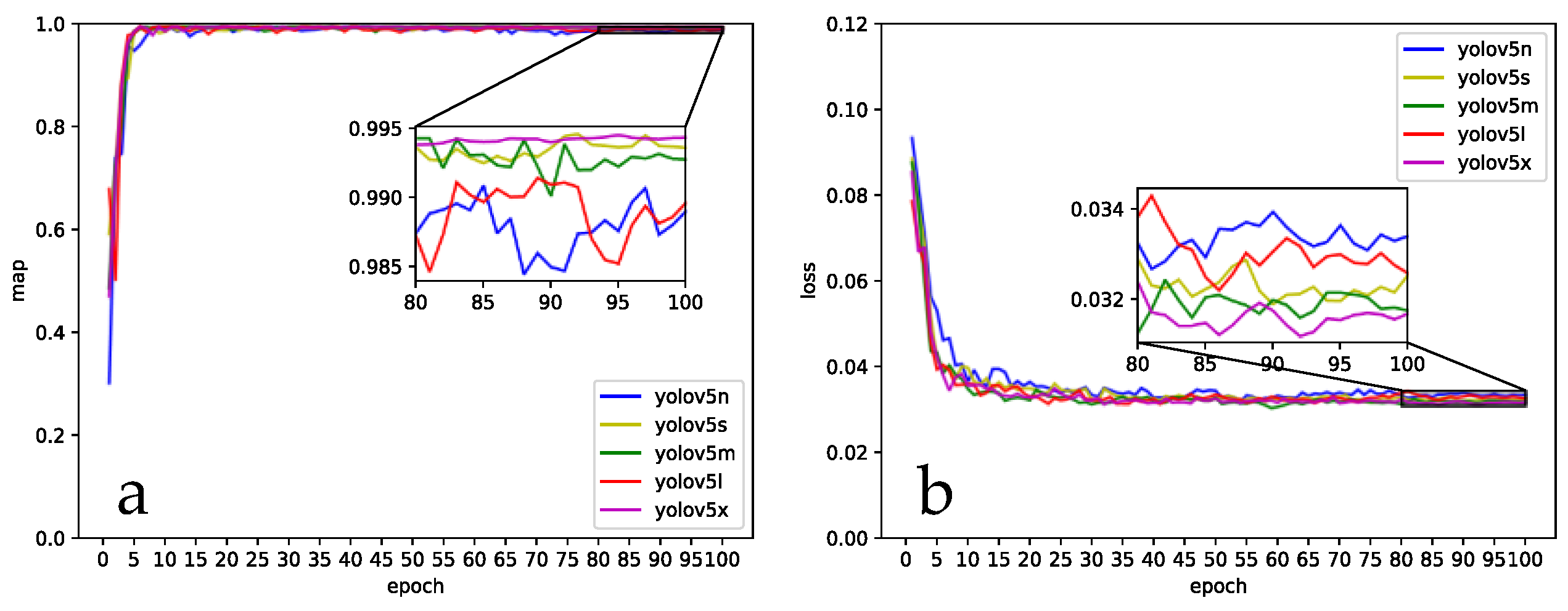
3.2. Model Training
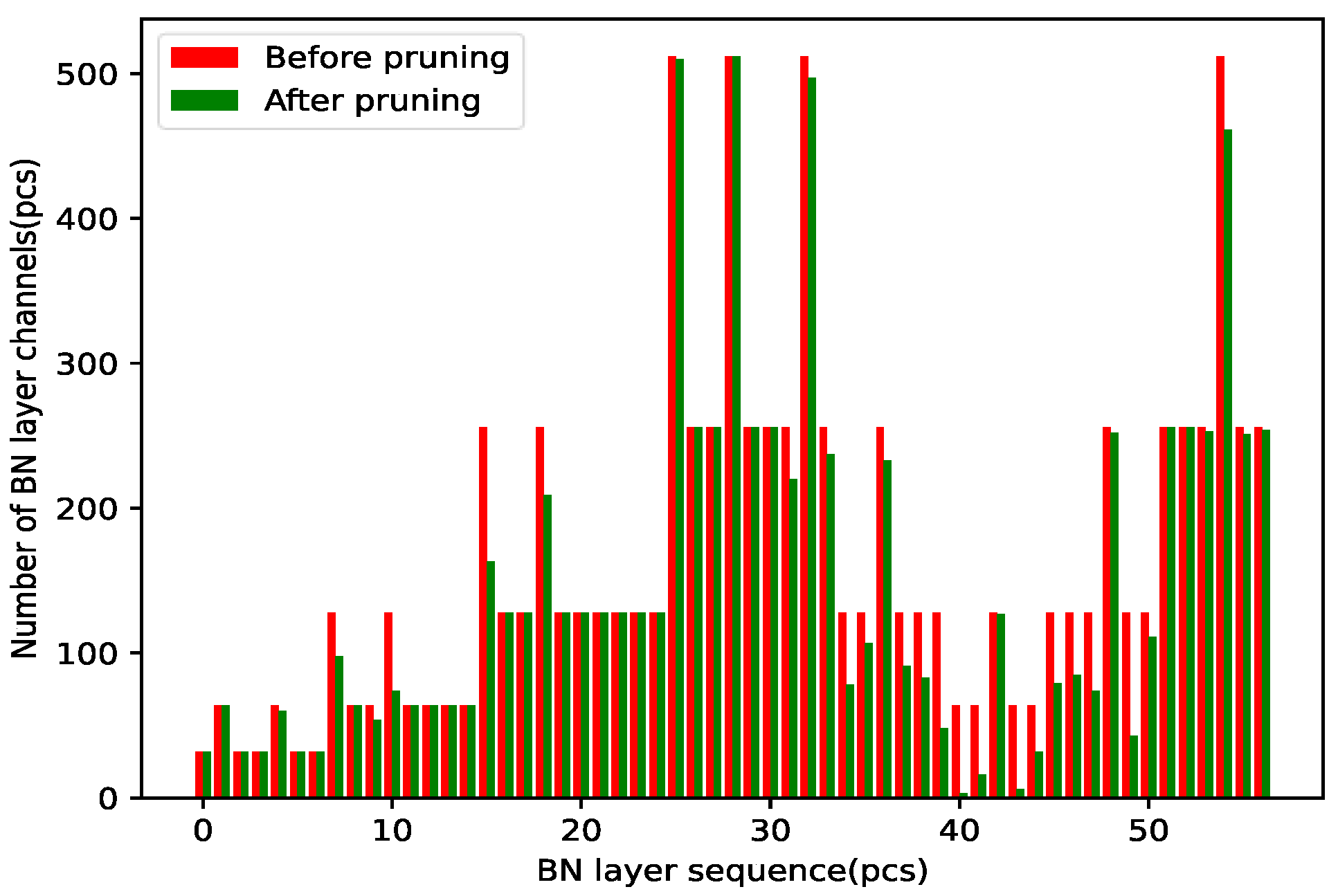
3.3. Model Pruning
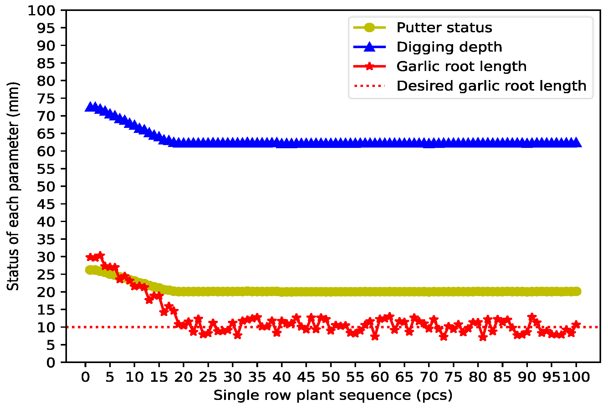
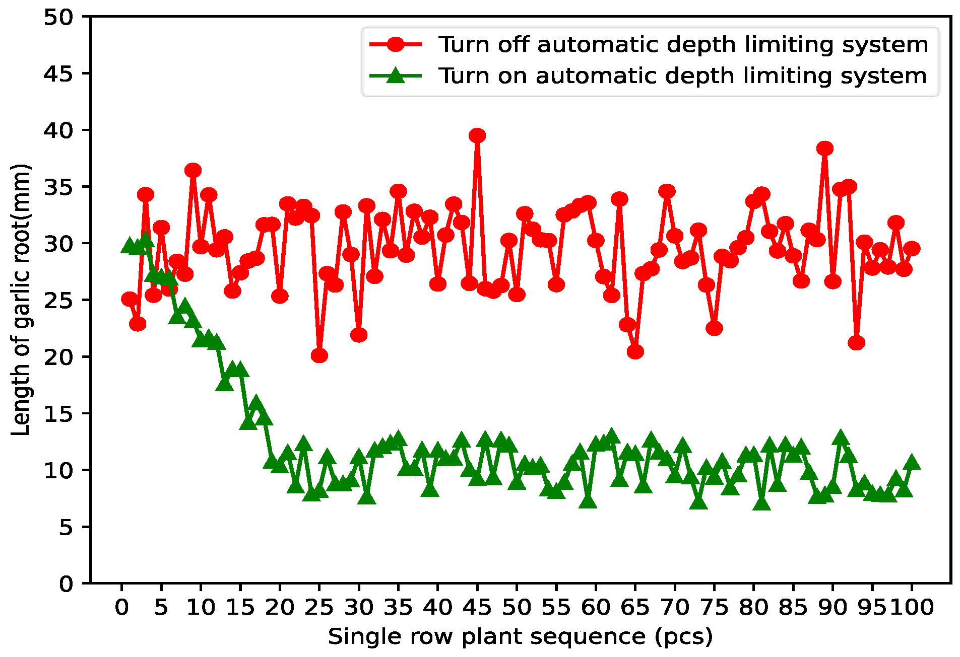
3.4. Control System Experiment
4. Discussion
5. Conclusions
Author Contributions
Funding
Institutional Review Board Statement
Data Availability Statement
Conflicts of Interest
References
- Shen, S.; Wang, D.; Yin, Y.; He, X.; Shang, S.; Zhao, Z.; Zheng, X. Design and Experimental Analysis of Deep-limiting Excavation Device of Garlic Harvester. Agric. Eng. 2022, 12, 107–111. [Google Scholar] [CrossRef]
- Zhao, D.; Cai, D.; Qin, L.; Gao, X.; Huang, W.; Liu, C. Design and Experiment of Modularized Garlic Combine Harvester. Trans. Chin. Soc. Agric. Mach. 2020, 51, 95–102. [Google Scholar]
- Yang, K.; Hu, Z.; Yu, Z.; Peng, B.; Zhang, Y.; Gu, F. Design and Experiment of Garlic Harvesting and Root Cutting Device Based on Deep Learning Target Determination. Trans. Chin. Soc. Agric. Mach. 2022, 53, 123–132. [Google Scholar]
- Yu, Z.; Hu, Z.; Yang, K.; Peng, B.; Zhang, Y.; Yang, M. Operation Mechanism Analysis and Parameter Optimization of Garlic Root Floating Cutting Device. Trans. Chin. Soc. Agric. Mach. 2021, 52, 111–119. [Google Scholar]
- Ma, K.; Zhang, R.; Xia, J.; Huo, L.; Han, Y.; Lv, P. Design and Experimental Study of Garlic Full-automatic Combine Harvester. Agric. Eng. 2019, 9, 90–94. [Google Scholar]
- Wang, H.; Li, T.; Wu, Y.; Geng, A.; Li, Y.; Hou, J. Research Status and Prospects of Garlic Harvesting Machinery. J. Chin. Agric. Mech. 2018, 39, 102–107. [Google Scholar] [CrossRef]
- Niu, M.; Zhou, J.; Zhang, H.; Fan, B.; Zhu, Z.; Wei, X.; Li, N. Research Advances in Garlic Harvesting Machinery. Agric. Equip. Veh. Eng. 2019, 57, 182–186. [Google Scholar]
- Zhang, M.; Sun, Z.; Sun, Z.; Chen, Q. Research Progress of Crop Mechanical Harvesting Technology. J. Anhui Agric. Sci. 2017, 45, 199–203. [Google Scholar] [CrossRef]
- Cui, R.; Zhang, H.; Xu, W.; Ma, J.; Sun, G. Discussion on the Present Situation and Development of Garlic Mechanized Production in China. J. Agric. Mech. Res. 2015, 37, 264–268. [Google Scholar] [CrossRef]
- Yu, X.; Hu, Z.; Hu, L.; Peng, B. Working Performance Test and Analysis on 4DLB-2 Garlic Combine Harvester. J. China Agric. Univ. 2013, 18, 183–187. [Google Scholar]
- Yang, H.; Hu, Z.; Peng, B.; Wang, B.; Zhang, Y.; Yu, Z. Design and Test of Collecting and Conveying Device of Garlic Multi-row Combine Harvester. J. Chin. Agric. Mech. 2021, 42, 8–12. [Google Scholar] [CrossRef]
- Chen, Z.; Zhang, C.; Hu, Z.; Wu, H.; Zhang, Y.; Peng, B.; Wang, B.; You, Z. Research Status and Prospects of Digging Depth—Controlled Technology for Under—Soil Fruit. J. Agric. Mech. Res. 2019, 41, 9–14+33. [Google Scholar] [CrossRef]
- Yuan, J.; Guo, X. Self-adaptation Control of Chassis System and Digging Shovel in Peanut Harvester. J. Agric. Mech. Res. 2014, 36, 10–13. [Google Scholar] [CrossRef]
- Wu, Q. GT170 Series Traction Potato Harvester of Grimme Company. Agricultural Engineering 2015, 5, 161–164. [Google Scholar]
- You, Z.; Wu, H.; Hu, Z.; Peng, B. Fuzzy Control on Digging Depth of 4HLB-2 Peanut Harvester. J. Northwest A F Univ. (Nat. Sci. Ed.) 2015, 43, 221–227. [Google Scholar] [CrossRef]
- Dai, H.; Dou, Y.; Wang, G.; Zhu, Z. An Automatic Excavation Depth Control System for Semi-feeding Four-row Peanut Combine Harvester. In Proceedings of the 2019 11th International Conference on Intelligent Human-Machine Systems and Cybernetics: IHMSC 2019, Hangzhou, China, 24–25 August 2019; Volume 1, pp. 184–187. [Google Scholar]
- Xiong, C.; Zhou, D.; Deng, G.; Li, G.; Cui, Z.; He, F.; Li, L. Design and Test of Automatic Control System for Excavation Depth of Vibrating Chain Cassava Harvester. J. Huazhong Agric. Univ. 2022, 41, 217–226. [Google Scholar] [CrossRef]
- Li, T.; Li, N.; Liu, C.; Zhu, Z.; Zhou, J.; Zhang, H. Development of Automatic Depth Control System Employed in Potato Harvester. Trans. Chin. Soc. Agric. Mach. 2021, 52, 16–23. [Google Scholar]
- Wang, L.; Li, T.; Niu, Z.; Wu, Y.; Han, K.; Yang, Q.; Jiang, G.; Hou, J. Design of the Sectional Type Garlic Harvester. J. Agric. Mech. Res. 2020, 42, 86–90. [Google Scholar] [CrossRef]
- Wu, Y.; Li, T.; Lin, L.; Hou, J.; Zhu, S. Design and Experiment of Disk Digging Device for Garlic. J. Chin. Agric. Mech. 2017, 38, 17–23. [Google Scholar] [CrossRef]
- Wang, C. Research on the Intelligent Adjustment and Control of the Garlic Sowing Depth. J. Agric. Mech. Res. 2018, 40, 185–188. [Google Scholar] [CrossRef]
- Ding, L.; Song, Z.; Xu, M.; Tao, C. Design of Embedded Measurement and Control System Based on STM32. J. Cent. South Univ. (Sci. Technol.) 2013, 44, 260–265. [Google Scholar]
- Zhang, Z. A Flexible New Technique for Camera Calibration. IEEE Trans. Pattern Anal. Mach. Intell. 2000, 22, 1330–1334. [Google Scholar] [CrossRef] [Green Version]
- Lv, J.; Xu, H.; Han, Y.; Lu, W.; Xu, L.; Rong, H.; Yang, B.; Zou, L.; Ma, Z. A visual identification method for the apple growth forms in the orchard. Comput. Electron. Agric. 2022, 197, 106954. [Google Scholar] [CrossRef]
- Ioffe, S.; Szegedy, C. Batch Normalization: Accelerating Deep Network Training by Reducing Internal Covariate Shift. In Proceedings of the 32nd International Conference on International Conference on Machine Learning, Lille, France, 6–11 July 2015. [Google Scholar]
- Thuyet, D.Q.; Kobayashi, Y.; Matsuo, M. A robot system equipped with deep convolutional neural network for autonomous grading and sorting of root-trimmed garlics. Comput. Electron. Agric. 2020, 178, 105727. [Google Scholar] [CrossRef]
- Li, S.; Li, B.; Li, J.; Liu, B.; Li, X. Semantic Segmentation Algorithm of Rice Small Target Based on Deep Learning. Agriculture 2022, 12, 1232. [Google Scholar] [CrossRef]
- Zhang, C.; Ding, H.; Shi, Q.; Wang, Y. Grape Cluster Real-Time Detection in Complex Natural Scenes Based on YOLOv5s Deep Learning Network. Agriculture 2022, 12, 1242. [Google Scholar] [CrossRef]
- Sun, H.; Li, S.; Li, M.; Liu, H.; Qiao, L.; Zhang, Y. Research Progress of Image Sensing and Deep Learning in Agriculture. Trans. Chin. Soc. Agric. Mach. 2020, 51, 1–17. [Google Scholar]
- Xu, H.; Sun, Y.; Cao, X.; Ji, C.; Chen, L.; Wang, H. Apple Quality Detection Based on Photon Transmission Simulation and Convolutional Neural Network. Trans. Chin. Soc. Agric. Mach. 2021, 52, 338–345. [Google Scholar]
- Li, X.; Ding, Q.; Sun, J.-Q. Remaining useful life estimation in prognostics using deep convolution neural networks. Reliab. Eng. Syst. Saf. 2018, 172, 1–11. [Google Scholar] [CrossRef] [Green Version]
- Ren, S.; He, K.; Girshick, R.; Sun, J. Faster R-CNN: Towards Real-Time Object Detection with Region Proposal Networks. IEEE Trans. Pattern Anal. Mach. Intell. 2017, 39, 1137–1149. [Google Scholar] [CrossRef] [Green Version]
- Liu, W.; Anguelov, D.; Erhan, D.; Szegedy, C.; Reed, S.; Fu, C.Y.; Berg, A.C. SSD: Single Shot MultiBox Detector; Springer: Berlin/Heidelberg, Germany, 2015. [Google Scholar]
- Redmon, J.; Farhadi, A. YOLO9000: Better, Faster, Stronger. In Proceedings of the IEEE Conference on Computer Vision & Pattern Recognition, Honolulu, HI, USA, 21–26 July 2017; pp. 6517–6525. [Google Scholar]
- Li, Y.; Guo, J.; Guo, X.; Zhao, J.; Tian, Y. Toward in situ zooplankton detection with a densely connected YOLOV3 model. Appl. Ocean Res. 2021, 114, 102783. [Google Scholar] [CrossRef]
- Ec, A.; Lin, T.B.; Zm, A.; Min, Z.C. ERF-YOLO: A YOLO algorithm compatible with fewer parameters and higher accuracy. Image Vis. Comput. 2021, 116, 104317. [Google Scholar]
- Choi, J.-Y.; Seo, K.; Cho, J.-S.; Moon, K.-D. Applying convolutional neural networks to assess the external quality of strawberries. J. Food Compos. Anal. 2021, 102, 104071. [Google Scholar] [CrossRef]
- Wu, D.; Lv, S.; Jiang, M.; Song, H. Using channel pruning-based YOLO v4 deep learning algorithm for the real-time and accurate detection of apple flowers in natural environments. Comput. Electron. Agric. 2020, 178, 105742. [Google Scholar] [CrossRef]
- Ye, C.-w.; Yu, Z.-w.; Kang, R.; Yousaf, K.; Qi, C.; Chen, K.-j.; Huang, Y.-p. An experimental study of stunned state detection for broiler chickens using an improved convolution neural network algorithm. Comput. Electron. Agric. 2020, 170, 105284. [Google Scholar] [CrossRef]
- Zhao, G.; Quan, L.; Li, H.; Feng, H.; Li, S.; Zhang, S.; Liu, R. Real-time recognition system of soybean seed full-surface defects based on deep learning. Comput. Electron. Agric. 2021, 187, 106230. [Google Scholar] [CrossRef]


| Camera Parameters | Parameter Value |
|---|---|
| Intrinsic Matrix | |
| Radial Distortion | |
| Tangential Distortion |
| Models | Model Size | Detection Time | Average Accuracy |
|---|---|---|---|
| YOLOv5n | 3.69 MB | 23.4 ms | 98.9% |
| YOLOv5s | 13.7 MB | 27.0 ms | 99.4% |
| YOLOv5m | 40.2 MB | 40.1 ms | 99.3% |
| YOLOv5l | 88.5 MB | 60.9 ms | 99.0% |
| YOLOv5x | 165 MB | 110.4 ms | 99.4% |
| YOLOv5s | Model Size | Detection Time | Average Accuracy |
|---|---|---|---|
| Before pruning | 13.7 MB | 30.7 ms | 99.2% |
| After pruning | 11.4 MB | 30.4 ms | 99.1% |
Publisher’s Note: MDPI stays neutral with regard to jurisdictional claims in published maps and institutional affiliations. |
© 2022 by the authors. Licensee MDPI, Basel, Switzerland. This article is an open access article distributed under the terms and conditions of the Creative Commons Attribution (CC BY) license (https://creativecommons.org/licenses/by/4.0/).
Share and Cite
Ding, A.; Peng, B.; Yang, K.; Zhang, Y.; Yang, X.; Zou, X.; Zhu, Z. Design of a Machine Vision-Based Automatic Digging Depth Control System for Garlic Combine Harvester. Agriculture 2022, 12, 2119. https://doi.org/10.3390/agriculture12122119
Ding A, Peng B, Yang K, Zhang Y, Yang X, Zou X, Zhu Z. Design of a Machine Vision-Based Automatic Digging Depth Control System for Garlic Combine Harvester. Agriculture. 2022; 12(12):2119. https://doi.org/10.3390/agriculture12122119
Chicago/Turabian StyleDing, Anlan, Baoliang Peng, Ke Yang, Yanhua Zhang, Xiaoxuan Yang, Xiuguo Zou, and Zhangqing Zhu. 2022. "Design of a Machine Vision-Based Automatic Digging Depth Control System for Garlic Combine Harvester" Agriculture 12, no. 12: 2119. https://doi.org/10.3390/agriculture12122119
APA StyleDing, A., Peng, B., Yang, K., Zhang, Y., Yang, X., Zou, X., & Zhu, Z. (2022). Design of a Machine Vision-Based Automatic Digging Depth Control System for Garlic Combine Harvester. Agriculture, 12(12), 2119. https://doi.org/10.3390/agriculture12122119