Article

Method Research and Structural Design of Segmented Shrimp Clamping

1
Key Laboratory of Modern Agricultural Intelligent Equipment in South China, Guangdong Institute of Modern Agricultural Equipment, Guangzhou 510630, China
2
The State Key Laboratory of Soil, Plant and Machine System Technology, Beijing 100083, China
*
Author to whom correspondence should be addressed.
Agriculture 2022, 12(12), 2118; https://doi.org/10.3390/agriculture12122118
Submission received: 11 November 2022 / Revised: 3 December 2022 / Accepted: 8 December 2022 / Published: 9 December 2022
(This article belongs to the Special Issue Machinery, Facilities and Installations for Food Industry)

Abstract

:
Clamping is the key factor that restricts the full-process mechanization of directional shrimp peeling. To solve the problem of difficult clamping caused by the uncertainty of shrimp position after orientation, a segmented shrimp clamping method was proposed by analyzing the relationship between shrimp conveying and clamping conditions. The contact force relationship on the shrimp meat was deduced based on mechanical analysis of the clamping process, and it was concluded that the number of segmented clamping units should be increased during the clamping process to reduce the pressure of the clamping units on the shrimp meat. A segmented shrimp clamping mechanism was designed for adaptive shrimp clamping, conveying and discharging. The profile curve model of the clamping surface was built by analyzing the shrimp section profile characteristics. According to ADAMS kinematics simulation analysis, no shrimp fell off or was damaged during the clamping process, which verified the design rationality of the segmented shrimp clamping mechanism. According to the single-factor test on a newly built shrimp clamping test bench, the optimal rotation speed range of the segmented clamping mechanism was found to be 10–20 r/min, the clamping success rate was over 92%, and the shrimp integrity rate was no less than 99%. The comparison test and performance test results showed that the segmented clamping mechanism had stronger adaptability and better clamping effect under the condition of variable interval feeding. Therefore, the segmented clamping mechanism is capable of practical application and can create stable clamping conditions for shrimp peeling.

1. Introduction

Penaeus vannamei is the main economic shrimp in the world; China, India, Vietnam, Ecuador, Indonesia, and Thailand being the major shrimp producers [1,2]. It is the most widely farmed shrimp in the world because of its fast production speed, wide temperature and salt tolerance, strong disease resistance and low nutritional requirements [3]. Shrimp meat is the main product of primary shrimp processing. Shrimp meat is delicious, nutritious, high in protein, low in fat, and rich in various minerals. It is a high-quality ingredient for cooking and making a variety of flavored foods, and is popular for consumers around the world [4,5]. As the shrimp processing industry develops and labor costs rise, the traditional method of manual peeling can no longer meet the requirements of large-scale shrimp production. Mechanized directional peeling is the main method for high-quality shrimp production.
The directional peeling process mainly includes sorting and orientation, clamping, back cutting, deveining, and meat removal [6,7,8]. The peeling process adopts the mode of one-by-one processing, which can achieve the effect of deveining as well as peeling. Clamping is the key to directional peeling of shrimps. Its main purpose is to stabilize the position of shrimps and create conditions for back cutting, deveining and meat removal. The requirement for clamping is to clamp the shrimp one by one and expose the back of the shrimp. At present, there are mainly two shrimp clamping methods: station-type clamping and belt-type clamping. The rotary shrimp peeling machine developed by Jonsson Company in the United States uses a station-type clamping mechanism [9,10,11], which can clamp the tail and stably support both sides of the shrimp. The clamping mechanism ensures the stability of clamping, which is one of the reasons why the machine can process various types of shrimps. The belt-type clamping mechanism is designed by Hebei Agricultural University and is mainly used for cutting the back of shrimps [12,13]. The mechanism consists of two conveyor belts side by side to form a V-shaped angle. The shrimp can be placed in the V-shaped groove. The two belts apply pressure on both sides of the shrimp body to clamp the shrimp, and the belt moves synchronously to convey the shrimp. The belt-type clamping is not as stable and adaptable as the station-type clamping. The station-type clamping mechanism has strict requirements on the position of shrimp clamping [14,15,16]. Because the station-type clamping has high requirements on the shrimp conveying position and distance, the shrimp should be placed in a fixed spacing and posture during the feeding process; otherwise, the clamping mechanism cannot stably clamp the shrimp [17,18,19,20]. The clamping requirements of shrimp orientation and positioning make it difficult to automate shrimp feeding. At present, there is no effective solution in industrial application, and the feeding link of the shrimp peeling machine still relies on manual work. Therefore, the clamping mechanism is the key factor that restricts the full-process mechanization of directional shrimp peeling. It is an effective way to reduce the difficulty of shrimp sorting and orientation and realize automatic feeding by getting rid of the requirements of the clamping mechanism on the posture and position of shrimp and realizing adaptive shrimp clamping.
Based on the directional posture of the shrimps of the symmetrically supported directional conveying mechanism, this paper achieves a number of goals. It analyzes the matching relationship between the clamping mechanism and the shrimp conveying conditions; proposes a segmented shrimp clamping method; designs a segmented shrimp clamping mechanism; and carries out test and verification. Thereby, it offers a solution to the problem of difficult clamping caused by the uncertainty of shrimp position after orientation and provide a reference for the in-depth research and application of non-positioning adaptive shrimp clamping technology.

2. Materials and Methods

2.1. Shrimp Clamping Method

2.1.1. Analysis of Clamping Conditions

The shrimp in the dorsal or ventral direction looks like an isosceles trapezoid, and its thickness gradually decreases from the head to the tail. When a pair of symmetrical supporting forces is applied on both sides of the shrimp, the two supporting forces and the shrimp’s own gravity form a three-force equilibrium state. The shrimp is head-up and tail-down when its body maintains a stable posture. Therefore, a symmetrical support method for orienting the shrimp head and tail is proposed based on the shrimp shape and physical characteristics. Based on the thickness difference between the shrimp head and tail and the symmetrical shape characteristics on both sides, the method enables the shrimp to maintain the lateral constraint posture, and automatically adjusts the head and tail direction by gravity by applying symmetrical support force to the shrimp through the lateral support action points A and B. Figure 1 illustrates the method. After head-to-tail turning, the shrimp can be stabilized in the head-up and tail-down posture to orientate the head and tail. The synchronous movement of the double round belts in the same direction can make the shrimp follow the round belt to move forward under the drive of the friction force, so as to achieve the purpose of orientation and transportation.
The position of the shrimp after orientation is shown in Figure 2, indicating that the spacing of the shrimps is inconsistent and the tails are not on the same horizontal line. As the spacing of the shrimps could not be guaranteed to be consistent during feeding, the ventral-dorsal shunt process further increases the spacing difference, and the spacing of the shrimps after orientation is inconsistent. The oriented shrimps are in a vertical posture with the head above and the tail below, and are supported by the conveying track. Due to the differences in length, thickness and bending degree of shrimps of the same size, the tails of the shrimps are not on the same horizontal line after orientation, and the height of the shrimp tails are inconsistent.
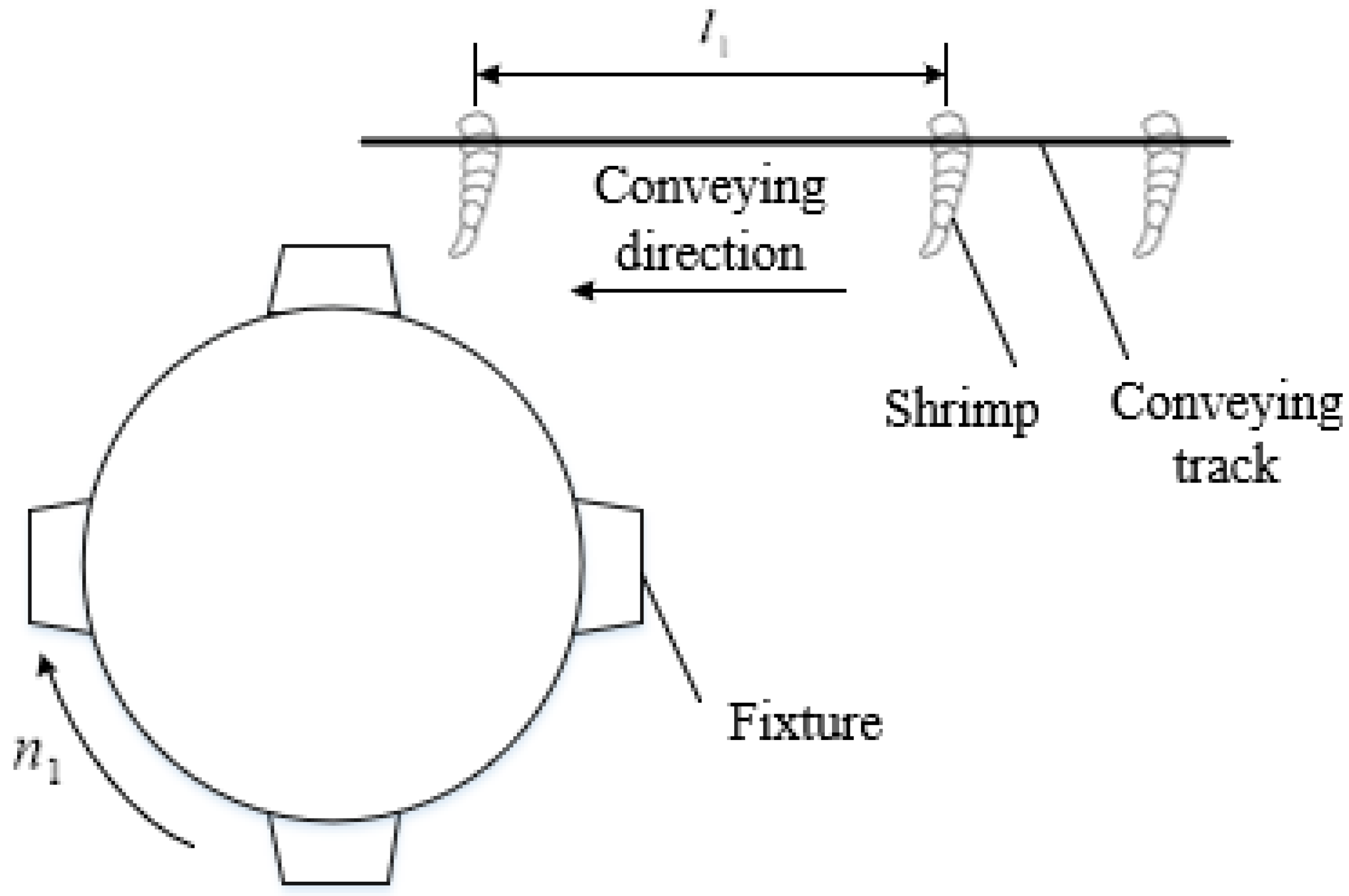
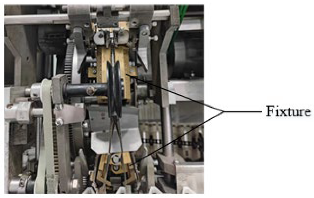
According to the directional peeling process, the circular-moving fixture for cyclic clamping can be suitable for the pipelined peeling process. Figure 3 shows the cycle clamping fixture. To ensure that the shrimps are successfully clamped and the fixture can reach the clamping position on time when transported to the end of the track, the matching relationship between the shrimp conveying time and the fixture arrival time should meet the following formula:
t 3 = 60 n 1 k 1 t 3 = t 2 t 2 = l 1 v 2
where t 3 is the time for the fixture to rotate to the clamping position, s; t 2 is the time for the shrimp to be transported to the clamping position, s; k 1 is the number of fixtures, pcs; v 2 is the shrimp conveying speed, m/s; n 1 is the rotation speed of the fixture, r/min; and l 1 is the distance between the shrimps, m.
According to Formula (1):
k 1 = 60 v 2 n 1 l 1
It can be seen from the analysis that the conveying speed remains constant during the working process of the orientation mechanism, so v is a fixed value. To ensure the stability and continuity of back cutting, deveining and meat removal, the clamped shrimps generally need to maintain a uniform motion, so n 1 is also a fixed value. According to Formula (2), k 1 and l 1 are inversely proportional. Because l 1 is changing, the number of fixtures would need to be changed at any time according to the change of shrimp spacing, which is obviously unrealistic.

2.1.2. Proposed Segmented Clamping Method

To ensure that the shrimp reaching the clamping position can match the fixture, the idea of differential approximation was adopted. Because t 3 is uniform and t 2 is constantly changing, the arrival time of the fixture can be made close to t 2 by minimizing t 3 and maximizing the number of stacks k 2 , that is, k 2 t 3 t 2 . According to Formula (1), the increase of k 1 can make t 3 smaller. Therefore, maximizing the number of figures on the circumference can reduce the influence of inconsistent shrimp spacing on the clamping.
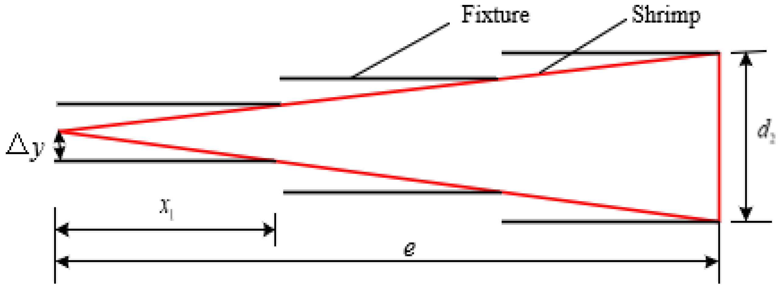
The traditional clamping method is that one fixture clamps one shrimp, and the profile of the fixture is designed according to the thickness change of the shrimp, so there are higher requirements for the position of the fixture to clamp the shrimp. The inconsistent height of the shrimp tail will lead to a change in the position of the fixture to clamp the shrimp, and the inappropriate position will affect the clamping stability. To solve the problem that the clamping position cannot be determined due to the inconsistent height of the shrimp tail, a segmented clamping method of multi-segment clamping and multi-point force application is adopted based on the differential idea. Assuming that the thickness of shrimps varies uniformly, the schematic diagram of segmented clamping is shown in Figure 4.
According to Figure 4:
e = k 1 x 1 d 1 = 2 k 1 Δ y k 1 1
where e is the length of a single shrimp, m; x 1 is the length of the clamp, m; d 2 is the maximum thickness of the shrimp, m; and Δ y is the distance between the fixture and the shrimp body, m.
According to Formula (3):
x 1 = 2 e Δ y d 2
Δ y is the reason why the shrimps cannot be clamped stably, and its reduction can improve the clamping of the shrimps. Because x 1 is proportional to Δ y and inversely proportional to k 1 , decreasing x 1 can decrease Δ y and increase k 1 . Therefore, reducing the length of the fixture and increasing the number of clamps for clamping the shrimp can improve the clamping stability.
According to the above analysis, a segmented shrimp clamping method is proposed to solve the problem of inconsistent shrimp spacing and inconsistent shrimp tail height after orientation. The schematic diagram is shown in Figure 5. In this method, the clamping units are evenly distributed on the circumference by means of dense and uniform distribution of the unitized fixtures, so as to ensure that there are clamping units in an open state in the clamping station at any time. Multiple continuous clamping units can freely form a fixture according to the length and position of the shrimps, and multiple clamping units clamp the shrimps in sections, which achieves adaptive clamping through segmented clamping and multi-point force application.

2.1.3. Influence of Segmented Clamping on Peeling

The positioning and clamping of the shrimps provides a guarantee for the subsequent back cutting, deveining and meat removal. Therefore, the main evaluation criteria of the shrimp clamping are the smooth process of back cutting, deveining and meat removal. The force analysis of each peeling process is required.
The back cutting, deveining and meat removal processes are all carried out from the back of the shrimp. The shrimp will be subjected to the force exerted by the back cutting knife, the brush and the meat removal needle at different times, and the force direction is opposite to the movement direction of the shrimp. Figure 6 shows the force analysis on the shrimp during back cutting or deveining. In the back-opening process, the shrimp is subjected to the pulling force exerted by the back-opening knife; in the deveining process, the shrimp is subjected to the friction force exerted by the brush.
In order to ensure the smooth realization of the back opening or catgut removal process, the shrimp was stably clamped without movement or rotation relative to the clamping plate when the force is applied by the back opening knife or brush. Therefore, the stress relationship meets the following formula:
i = 1 n 2 f n cos α n > F k G + i = 1 n 2 f n sin α n > G w 2 r g i = 1 n 2 f n l n > F k l f n = F n μ 2
where, F k is the force of the back-opening knife or the brush on the shrimp body, N; F n is the pressure on the shrimps by the clamping plate, N; f n is the friction force of the n-th clamping plate on the shrimp, N; μ 2 is the coefficient of kinetic friction between the shrimp and the clamping plate; α n is the angle between friction and horizontal direction, °; G is the force of gravity acting on the shrimp, N; w is the angular velocity of the clamping mechanism, rad/s; r is the radius of the clamping mechanism, m; l n is the distance between the center of gravity of the shrimp and the friction force, N; l is the distance between the center of gravity of the shrimp and F k , N; and n is the number of clamping units.
According to Formula (5), increasing the number of clamping units n and the clamping force F n can increase the friction on the shrimps and improve the stability of clamping, which facilitates back cutting and deveining.
In the process of meat removal, the meat removal needle needs to break the adhesion between the shrimp shell and meat to separate the shell from the kernel. Therefore, in the force analysis of the process of harvesting the kernels, the shrimps should be used as the force-bearing body, and the shrimps are subjected to the pulling force Fq of the kernels, the adhesion force Fz of the shell and the meat, and the friction force fm from the shrimp shell.
To remove the shrimp meat under the effect of the pulling force exerted by the shelling needle, the friction force and the adhesion force between the shell and the meat must be overcome to separate it from the shrimp shell. Therefore, the following formula should be met:
F z + i = 1 n 2 μ 3 F n cos β n < F q F q < F r i = 1 n 2 μ 3 F n sin β n > G 3 + G 3 w 2 r g
where, Fr is the breaking force of shrimp meat, N; μ 3 is the static friction coefficient between shrimp meat and shrimp shell; β n is the angle between the friction force and the horizontal direction, °; G 3 is the force of gravity acting on the shrimp, N; Fq is the tension exerted by the shelling needle on the shrimp, N; and Fz is the shell meat adhesion force, N.
According to Formula (6), the increase in F n and the increase in the number of clamping units will lead to an increase in the friction force between the shrimp shell and the shrimp meat. At this time, F q must be increased to realize the separation of the shell and kernel. When F q exceeds F r , the shrimp meat breaks, and the kernel extracting needle cannot exert a pulling force on the shrimp, and the meat removal fails. Therefore, the smaller the resistance of the kernel is, the easier the separation of the shell and kernel. The pressure on the shrimp meat is the main factor for the increase in the resistance to meat removal.
To sum up, the pressure on the shrimp is a key factor affecting peeling. Increasing the pressure of the clamping unit on the shrimp shell is beneficial to the process of back cutting and deveining, and reducing the pressure on the shrimp meat is beneficial to the meat removal process. Therefore, the segmented clamping method is beneficial to the process of back cutting, deveining and peeling. During the implementation of the method, the number of units to be clamped in sections should be increased, and the pressure of the clamping units on the shrimp meat should be reduced.

2.2. Design of Segmented Clamping Mechanism

2.2.1. Overall Structure and Working Principle

According to the design requirements, the shrimps with head-tail orientation and ventral-dorsal orientation need to be uniformly fixed to guarantee the subsequent processes of back cutting, deveining, and meat removal.
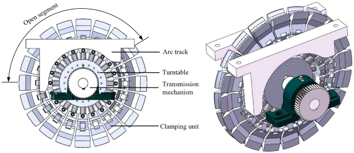
According to the segmented shrimp clamping method, a segmented shrimp clamping mechanism was designed, as shown in Figure 7. The mechanism is mainly composed of a clamping unit, a turntable, an arc track and a transmission mechanism. Several clamping units are evenly arranged around the turntable to form a segmented clamping turntable. The two arc tracks are respectively arranged on the two sides of the clamping turntable, the rolling parts on the clamping unit move on the curved surface of the track, and the clamping unit is opened and closed through the change of the track profile. The arc area formed by the arc track in Figure 6 is the opening section of the clamping unit. The clamping unit is closed under the action of its own spring force after leaving the track.
The working process of the mechanism is as follows: in the axial direction of the turntable, the clamping unit makes a circular movement driven by the rotational force of the turntable; and in the radial direction of the turntable, the clamping unit performs regular opening and closing movements under the track support force. Through the superposition of the two movements, the clamping structure realizes the directional clamping, conveying and discharging of the shrimps. The oriented shrimps fall into the clamping position from the top, and the clamping unit in the clamping position is in an open state at this time. The shrimp starts to rotate under the support of multiple clamping units, and then the clamping units are gradually closed under the driving of the change of the track surface. Each clamping unit automatically determines the opening angle of the clamping plate based on the thickness of the shrimp body to be clamped, so as to realize segmented adaptive clamping, and then gradually to carry out the processes of back cutting, deveining and kernel removing of the shrimp during the rotary conveying process. After the shell and kernel are separated, the shrimp shell continues to be clamped. When the clamping unit contacts the track again, the clamping unit is subjected to pressure to open the clamping plate, and the shrimp shell falls down. The clamping unit then continues to stay open and enters the next clamping cycle.

2.2.2. Design of Clamping Units

The overall structure of the clamping unit is similar to a mechanical claw, which is mainly composed of clamping claw, connecting rod, slider, support rod, spring and roller, as shown in Figure 8. The two clamping claws form a clamping actuator, and their opening and closing realize clamping and loosening. The structure design of the clamping unit is based on the crank-slider mechanism [21,22], and the clamping action is realized by the spring-driven slider movement.
Since the shrimp shell wraps the shrimp, when the shrimp is under pressure, the stress on the shrimp shell is the same as that on the shrimp, but the stress on the stomach and tail has no effect on the stress on the shrimp. Therefore, to solve the contradictory problem that the clamping force acts in opposite directions in different stripping processes, the method of applying force at multiple points can be adopted. Specifically, the clamping force should be applied to the shrimp body, the gastropod and the tail simultaneously to improve the clamping stability; meanwhile, the clamping force of the clamping plate to the stomach and tail should be increased, and the clamping force of the shrimp body should be reduced.
According to the characteristics of the cross-sectional profile of the shrimps, an adaptive clamping surface was designed based on the multi-point force application method, as shown in Figure 9. The clamping surface is formed by connecting four surfaces which are, in sequence from top to bottom: a supporting surface, an upper clamping surface, a transition surface and a lower clamping surface. The lower clamping surface is flat, and the other surfaces are curved. Two rows of conical protrusions are evenly distributed on the surface of the upper clamping surface. The lower clamping surface mainly clamps the stomach and tail; the upper clamping surface mainly clamps the shrimp body; and the transition surface realizes a smooth transition at the connection between the upper and lower clamping surfaces, and supports the shrimp. The supporting surface mainly provides a certain supporting force to the side of the shrimp, preventing the shrimp from shaking left and right, and improves the clamping stability.
The adaptive clamping surface is extruded from the clamping curve, so the design of the clamping curve was of key importance. The clamping curve was designed according to the profile of the radial section of the shrimp. Since the clamping units are evenly distributed on the turntable, any position of the shrimp can be clamped by the clamping unit. The clamping surface should adapt to the profiles of different parts of the shrimp. Therefore, a comprehensive clamping curve is designed according to the profile characteristics of the shrimp, as shown in Figure 10. Section A0B0 is the profile of the clamping surface for clamping the stomach and tail of the shrimp, B0C0 is the transition line, section C0D0 is the profile of the clamping surface that clamps the shrimp body, and D0E0 is the support curve of the shrimp body.
The plane rectangular coordinate system in Figure 10 was established with the rotation axis of the clamping claw as the origin. The clamping curve in the coordinate system is the profile of the clamping surface where the clamping plate is at the maximum angle. According to the shape parameters of shrimps, the curve equations of the designed comprehensive clamping curve are:
f ( x ) = 4.917 x 0.208 f ( x ) = 0.667 x + 9.567 f ( x ) = 1.76 x + 5.74 f ( x ) = 0.132 x 2 0.566 x + 14.97 ( 1.1 x 2.3 ) ( 2.3 x 3.5 ) ( 3.5 x 6 ) ( 6 x 9.9 )
As the shrimp is of circular arc shape, in order to make the clamping surface adapt to the shrimp shape, the final arc clamping surface is obtained by stretching a certain arc length of the comprehensive clamping line with the B0 point of the comprehensive clamping curve as the endpoint, with the abdominal arc profile of the shrimp in the natural state as the path. Therefore, the diameter of the whole clamping mechanism can be determined based on the curvature of the abdomen contour of the shrimp.
According to the analysis in Section 2.1.3, theoretically, the length of clamping surface should be reduced as much as possible, and the number of clamping units should be increased to achieve uniform clamping and improve the clamping stability. However, in terms of structural design, when the diameter of the clamping mechanism is fixed, the greater the number of clamping units, the smaller the size of the clamping units is. Too many clamping units will increase the complexity of the clamping mechanism and reduce the reliability of the whole mechanism. Therefore, it is necessary to determine the maximum length of the clamping surface required to keep the shrimp evenly clamped.
As the shrimp body is flexible, the pressure will cause deformation. According to the change relationship between the load and displacement in the shrimp compression test, the shrimp is in an elastic deformation state at the initial stage of pressure application, and larger deformation can be obtained by applying a smaller load. According to the shrimp compression test data, the force required for 2 mm compression displacement is 0.1 N, so it can be considered that the shrimp can contact the clamping surface evenly in the area with 2 mm thickness difference. Therefore, according to the mechanical properties of the shrimp, the maximum arc length of the clamping surface is determined to be 35 mm. Combined with the diameter of the shrimp clamping mechanism and the size of other components, the total number of clamping units of the clamping mechanism is finally determined to be 20.

2.2.3. Determination of Spring Parameters

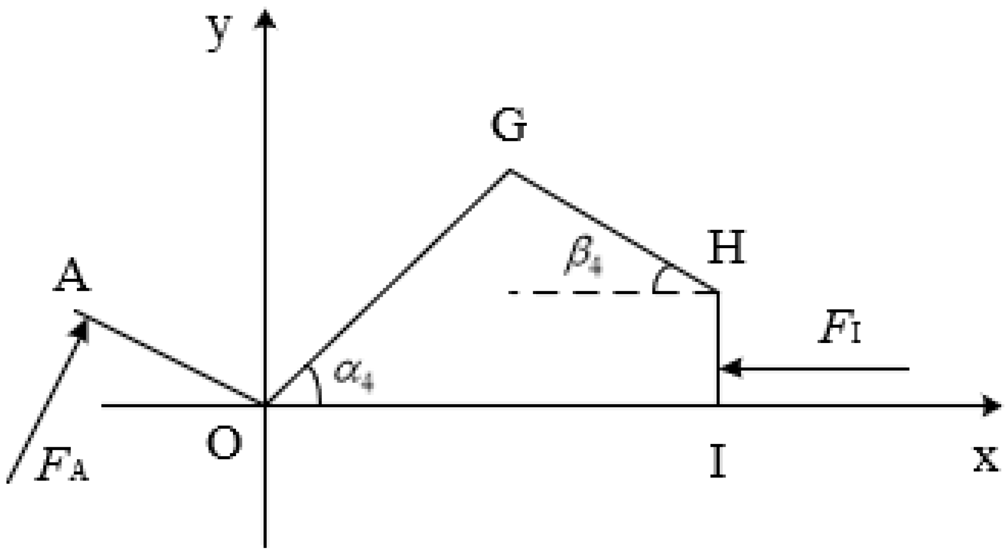
The structure of the clamping unit is shown in Figure 11, where the plane rectangular coordinate system is established with point O as the origin. The clamping plate AOG rotates around point O, and the slider HI slides along the x-axis.
According to the motion relationship, it can be considered that point H rotates around point G. Therefore, the intersection of the circle (whose center is point G and radius is lGH) with the straight line y = lHI is the coordinate of point H. If the coordinates of point H are set to ( x H , y H ), the following formula can be obtained:
( x H l OG cos α 4 ) 2 + ( l OG sin α 4 y H ) 2 = l GH 2 y H = l HI
According to Formula (8), the abscissa formula of point H can be obtained:
x H = l OG cos α 4 + l GH 2 ( l OG sin α 4 l HI ) 2
where α 4 is the angle between the rotating rod OG of the clamping claw and the x-axis (°).
The abscissa of point H is calculated to satisfy: 25 x H 29.3 . Since the abscissa range of point H is the compression stroke of the spring, the compression stroke of the spring during the entire movement of the clamping unit is 4.3 mm. According to the overall size design of the clamping mechanism, the spring length is 16 mm when the spring compression reaches the maximum value.
According to the force analysis in Figure 10, the clamping unit is subjected to the pressure FI of the spring and the support force FA of the shrimp. The force relationship of the clamping unit satisfies the following formula:
F A l OA = F G l OG sin α 4 + β 4 F I = 2 F H cos β 4 cos β 4 = x H l OG cos α 4 l GH
where F A is the support force of the shrimps on the clamping surface, N; F I is the spring force, N; and β 4 is the angle between the connecting rod GH and the horizontal line (°).
According to theoretical analysis, the clamping force required to achieve stable clamping of shrimp without causing damage to the shrimp meets the condition 2.5 N < F < 19.8 N. Since FA = F , the range of spring force obtained by substituting Formula (10) is 6.2 N < F I < 31.6 N, the spring is always compressed in the clamping unit. Since the spring force is at a minimum when compression is at a minimum, and vice versa, the following formula can be obtained:
( s 3 4.3 16 ) k 3 > 6.2 ( s 3 16 ) k 3 < 31.6
where s 3 is the total spring length, mm; and k 3 is the spring coefficient, N/mm.
The theoretical range for the spring coefficient is obtained from Formula (11):
6.2 s 3 20.3 < k 3 < 31.6 s 3 16
The maximum compression ratio of the commonly used spring is 75%, so the total length of the spring is limited by the compression ratio of the spring. Combined with Formula (12), the total spring length meets the following formula:
6.2 s 3 20.3 < 31.6 s 3 16 s 3 < 16 1 0.75
Therefore, the total length of the spring is 21.4 mm < s 3 < 64 mm. According to the theoretical range of the total spring length and spring coefficient, the parameters of the compression spring of the clamping unit are selected from the mechanical design manual. Finally, the total spring length is 35 mm and the spring elasticity coefficient is 0.49 N/mm.

2.2.4. Arc Track Design

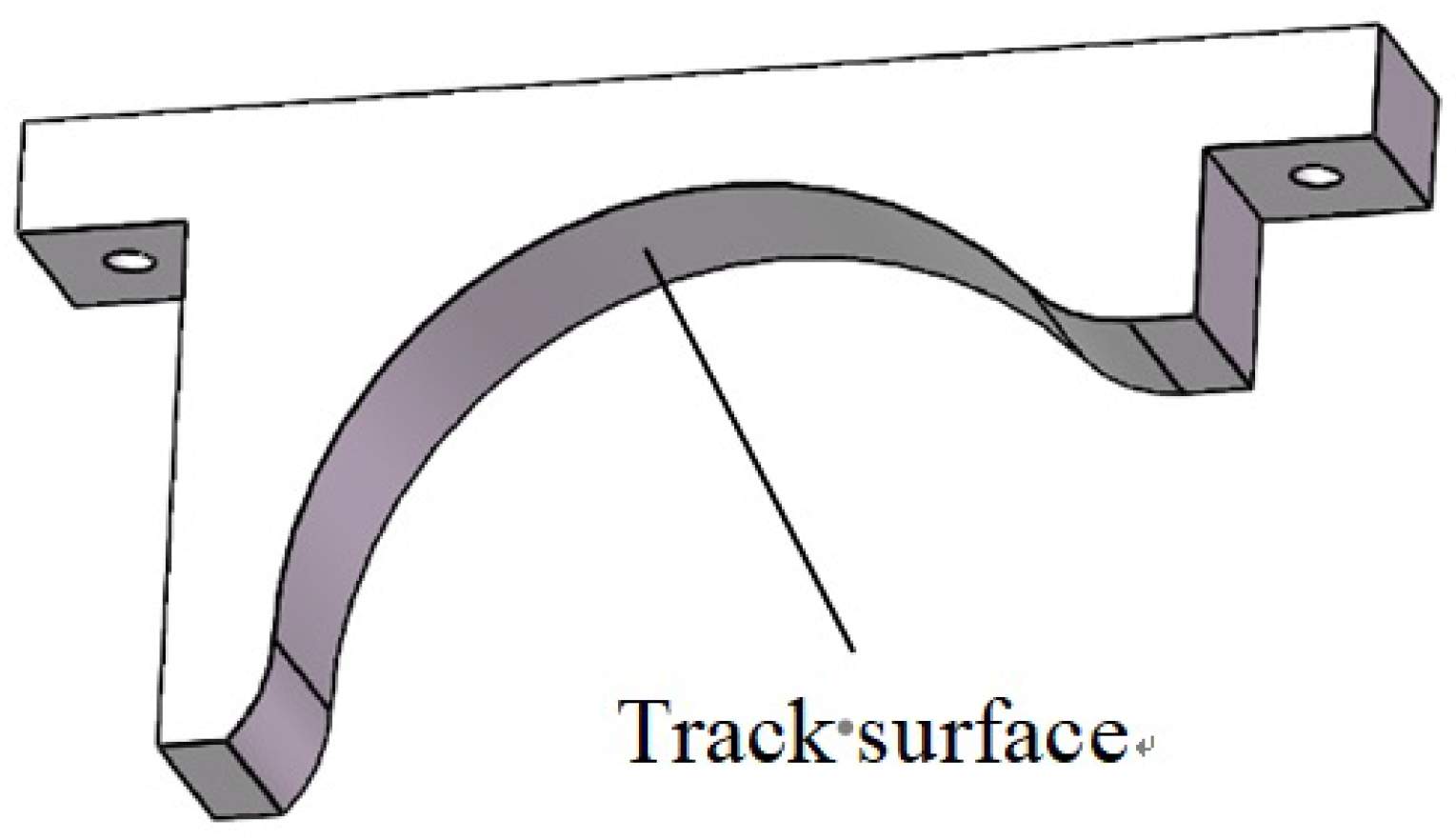
Due to the axisymmetric structure of the clamping unit, there is a small bearing on each side. To meet the requirement of uniform force during the opening process of the clamping unit, the clamping mechanism adopted a double-track design. That is, an identical track is provided on both sides of the clamping unit, and the track continuously exerts force on the clamping mechanism by rolling the small bearing on the track surface. Figure 12 shows the track design.
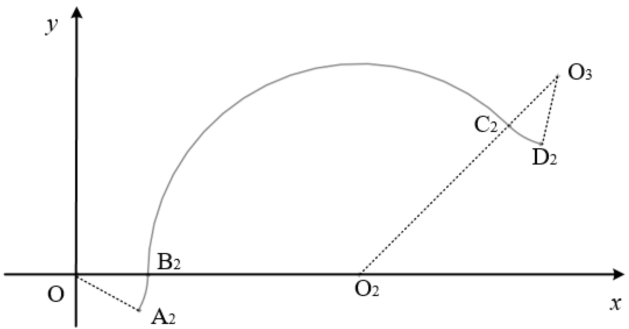
According to the working principle of the clamping mechanism, the movement process is divided into two parts: the closed section and the open section. Because the clamping unit of the closed section does not require the track to exert pressure, the track does not need to be designed in the closed section. Figure 13 shows the profile design of the track surface.
The curve A2B2C2D2 in Figure 13 is the profile of the track surface. The profile curve is divided into three sections, all of which are circular arc designs. Section A2B2 is an open transition area, as is B2C2, and C2D2 is a closed transition area. According to the analysis of the idling process that does not hold the shrimp, during the movement of the clamping unit from point A2 to point B2, the holding plate gradually changes from fully closed to fully open. During the movement of the clamping unit from point B2 to point C2, the clamping plate is always open. During the movement of the clamping unit from point C2 to point D2, the clamping plate is gradually closed. In other positions, the clamping plate is closed. When the shrimp is clamped, the A2B2 section is mainly the shedding of the shrimp shell. The clamping plate is opened so that the clamping force disappears, and the shrimp shell falls under the action of gravity. Section B2C2 is the area where the shrimp falls into the clamping mechanism. The opening of the clamping plate facilitates the entry of the shrimp into the clamping station. The C2D2 segment clamping plate gradually exerts pressure on the shrimp to achieve stable clamping.
According to the analysis, the profile model of the designed track surface is as follows:
A 2 B 2   curve : x = 25.2 cos θ y = 25.2 sin θ   ( 329.9 ° θ 360 ° ) B 2 C 2   curve : x = 76.5 cos θ + 101.7 y = 76.5 sin θ   ( 45 ° θ 180 ° ) C 2 D 2   curve : x = 25.2 cos θ + 173.7 y = 25.2 sin θ + 71.9   ( 225 ° θ 255.1 ° )

2.3. Clamping Mechanism Simulation Model Building

2.3.1. Modeling of Shrimp in 3D

To establish a 3D model of a shrimp based on reverse engineering theory, a 3D scanner was used to scan a shrimp [23,24]. The 3D scanning equipment uses a PTOP300B scanner, as shown in Figure 14. Its scanning mode is non-contact surface scanning, with the ability of 3D data collection, splicing and processing.
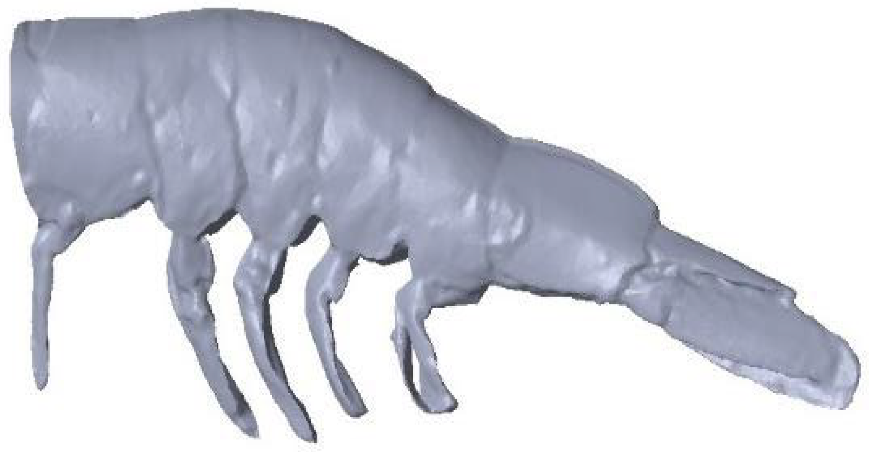
The 3D point cloud model of the shrimp was obtained by the scanner, and then the data was imported into the Geomagic Studio software for post-processing. Finally, the 3D model of the shrimp was obtained, as shown in Figure 15. The model provides support for the simulation analysis of the segmented clamping mechanism.

2.3.2. Simulation Model

The 3D model of the segmented clamping mechanism was established by SOLIDWORKS software. In the clamping mechanism and the shrimp action model, the shrimp is in contact with the clamping plate in a posture with the abdomen facing down and the tail consistent with the movement direction. The model was then imported into the ADAMS software, as shown in Figure 16. To simplify the motion analysis, only two sets of clamping units were set in the 3D model of the clamping mechanism.
After the model was imported into the simulation software, the direction of the 3D coordinate axis was defined in the software. According to the installation position and movement process of the clamping mechanism, the correct direction of the upper end of the rail is in the X direction, the vertical direction of the upper end of the rail is in the Y direction, and the vertical outward direction of the rail is in the Z direction. The negative direction of the Y direction is determined as the direction of gravitational acceleration.
On the Adams/view interface, the properties of the material are set by means of parameter input. Since the clamping mechanism is made of resin material, the density of the clamping mechanism is set to 1.14 g/cm3, the elastic modulus is 0.2 N/mm2, and the Poisson’s ratio is 0.39. To increase the simulation reliability, the shrimp model is set as a flexible body according to the physical characteristics of the shrimp.
Constraints are added to each component according to the movement characteristics of the clamping mechanism: a rotating pair is added to the double clamping plate; a rotating pair is added between the clamping plate and the connecting rod, and between the connecting rod and the slider; a moving pair is added between the slider and the support rod; a rotating pair is added between the roller and the support pin; a rotating pair is added to the turntable; and a fixed pair is added to the track. Finally, a rotary drive is added to the rotary pair of the turntable.

2.4. Shrimp Clamping Test Arrangement

2.4.1. Single Factor Test

To verify the clamping effect of the segmented clamping mechanism, a shrimp clamping test bench was built, as shown in Figure 17. During the clamping process, the shrimps are put into the clamping unit from the top of the turntable with the abdomen downward and the tail forward. The clamping turntable rotates counterclockwise for clamping and loosening.
Frozen Penaeus vannamei of size 2 and size 6 are used as the test objects, and the heads are removed after thawing. Keeping the shrimp feeding rate constant, the single-factor test was conducted with the rotation speed of the turntable as the test factor and the clamping success rate and shrimp integrity rate as the indicators. If the shrimps remained in the clamping state in the clamping section of the turntable without falling, it was regarded as successful clamping. If the shrimps were not broken and damaged, the shrimps were regarded as complete.
During the test, the shrimps were continuously placed into the holding plate with the abdomen downward and the tail facing the same direction as the rotation direction of the turntable, and the clamping and peeling were started. According to the optimal discharge rate of the shrimp separation and sorting mechanism, the feeding rate of the shrimp during the test did not exceed 82 pcs/min. Because the test adopted manual feeding, according to the normal manual feeding speed, 60 shrimps were evenly fed within 1 min in each test. At the end of each test, the numbers of abnormally dropped shrimps and of damaged shrimps were counted.
The clamping success rate and shrimp integrity rate were calculated according to Formulas (15) and (16), respectively.
Clamping success rate:
p 1 = j j 1 j × 100 %
Shrimp integrity rate:
p 2 = j j 2 j × 100 %
where, j is the shrimp feeding quantity, pcs; j 1 is the number of abnormal dropped shrimps, pcs; and j 2 is the number of damaged shrimps, pcs.
According to the theoretical range of the rotation speed of the turntable and the results of the pre-test, the rotation speed of the turntable was in the range of 10–30 r/min. Five levels of factor tests were set up with a gradient of 5 r/min. Each group of tests were repeated 3 times, and the test results were averaged [25,26,27].

2.4.2. Comparison Test

The design of the segmented clamping mechanism was to solve the problems of how to stably clamp shrimps when the feed spacing is uncertain, and of how to create conditions for the subsequent shelling process. In order to test the clamping adaptability of the segmented clamping mechanism, the turntable fixture clamping mechanism was selected as the control group, and the comparative test of the clamping effects of the two clamping mechanisms was carried out [28,29,30,31].
The turntable fixture clamping mechanism is shown in Figure 18. The mechanism has four evenly distributed clamps: each clamp can only hold one shrimp, so the mechanism needs to load at a fixed distance and a fixed point. The manual feeding rate was set to 60 pieces/min. According to the feeding rate and the working mode of the turntable fixture clamping mechanism, the normal speed of the turntable fixture clamping mechanism was determined to be 15 r/min. To ensure consistency, the rotating speed of the segmented clamping mechanism was set to 15 r/min.
The experiment was carried out in accordance with the single factor test method by using two methods of equal interval uniform feeding and variable interval feeding to test the clamping success rate and the shrimp integrity rate of the two clamping mechanisms.

2.4.3. Performance Test

In order to study the working performance of the segmented clamping mechanism in the shrimp shelling process, a shrimp directional peeling test device was built based on the shrimp clamping test bench. The test device is mainly composed of a segmented clamping mechanism, back opening mechanism, catgut removal mechanism, core removal mechanism and shell removal mechanism, as shown in Figure 19. Each working mechanism is distributed around the segmented clamping mechanism. Under the rotating action of the clamping mechanism, the back opening, intestines removal, and peeling of shrimp are completed successively, and finally shrimp meat is produced.
According to the previous research test, the optimized working parameters of the test device were determined as follows: the rotating speed of the clamping turntable was 12 r/min, the rotating speed of the back opening knife was 200 r/min, the rotating speed of the catgut removal mechanism was 60 r/min, and the rotating speed of the shell removal mechanism was 30 r/min. The performance test was carried out with the shrimp peeling success rate and processing capacity as indicators. The shrimp of size 2 and size 6 wereused as the test objects, and each group of tests was repeated 3 times.
Processing capacity is given by:
Y 5 = J T
where Y 5 is the processing capacity, pcs/h; J is the total number of shrimp processed by the peeling device, pcs; and T is the working time of the peeling device, h.

3. Results and Discussion

3.1. Simulation Results and Discussion

After the model of the clamping mechanism was established in ADAMS, the ADAMS Solver was called for simulation [32,33], and the simulation time was set to 4 s while the number of steps was set to 200. According to the theoretical rotation speed range of the clamping mechanism, the rotation speed of the turntable was set to 20 r/min, and the clamping of the clamping mechanism was analyzed. After the simulation was completed, the data of the movement process of the key parts was selected for analysis. Figure 20 shows a simulation of the shrimp clamping process.
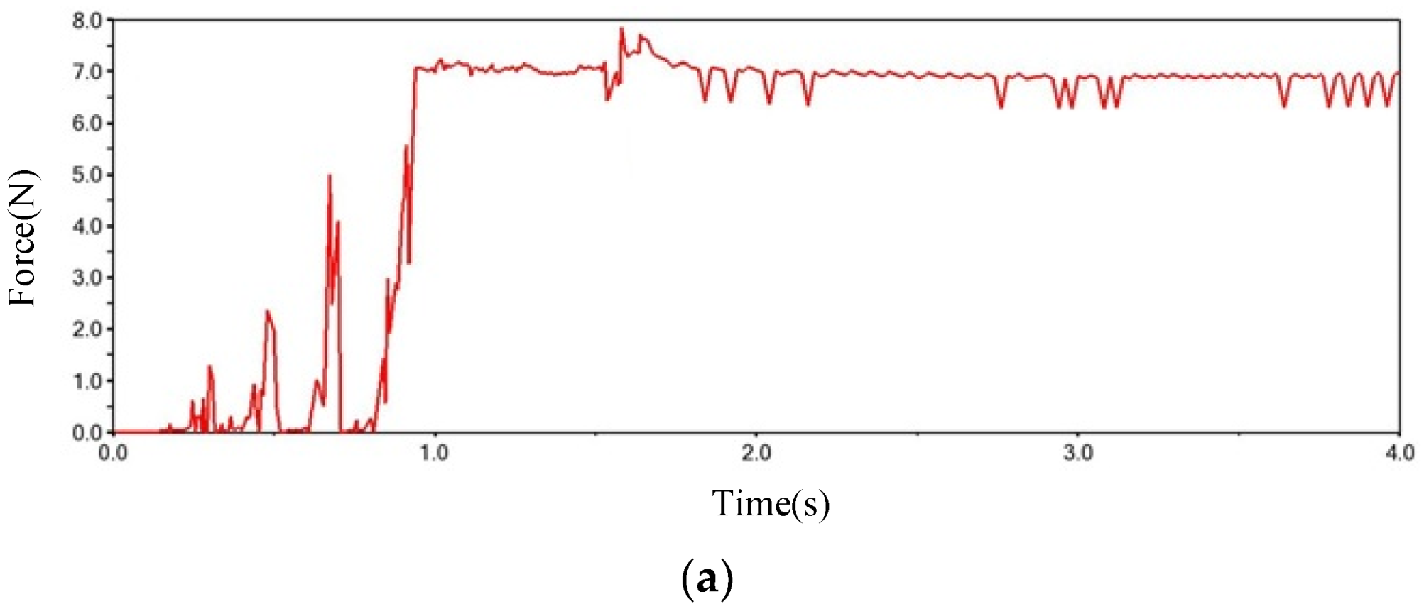
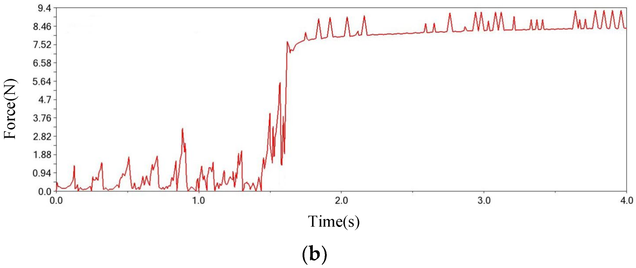
According to the motion process of the simulation animation, the shrimps could be clamped by the clamping mechanism, with no clamping failure such as the shrimps falling out of the clamp. Since the contact force of the clamping plate in the Z direction was the clamping force of the clamping plate on the shrimp, in order to analyze the clamping of the shrimp, the output of the post-processing module was the time-varying data of the contact force of the clamping plates of the two clamping units in the Z direction, as shown in Figure 21.
According to analysis of the curve changes in Figure 21, the overall change laws of the contact forces of the front and rear clamping plates were the same: as time passed by, the contact force was first at a lower value, then gradually increased to the maximum value, and then remained at the maximum value. The time point when the contact force of the front clamping plate reached the maximum value was 0.9 s, and for the rear clamping plate it was 1.6 s. The time points of the two successively coincided with the time points of the two clamping units leaving the track, indicating that the clamping force of the clamping plate on the shrimp was small before reaching the clamping position; moreover, the clamping plate gradually closed after reaching the clamping position, and the clamping force increased rapidly. After the force of the shrimp was balanced, the clamping force remained stable. According to the contact force data, the maximum contact force of the front and rear clamping plates were 7.9 N and 9.3 N, respectively. Since the position of the front clamping plate holding the shrimps was inclined to the tail, and the position of the rear clamping plate holding the shrimps was inclined to the head, the different thicknesses of the shrimps at the clamping position led to different opening angles of the clamping plates. The clamping force of the front clamping plate was less than the clamping force of the rear clamping plate. According to the theoretical analysis, the range of the clamping force should meet the requirements of 2.5 N < F < 19.8 N, so the results of the clamping force in the simulation test met the requirements. The clamping mechanism realized the stable clamping of the shrimp, and the clamping force did not cause damage to the shrimp.

3.2. Test Results and Discussion

3.2.1. Single Factor Test Results and Analysis

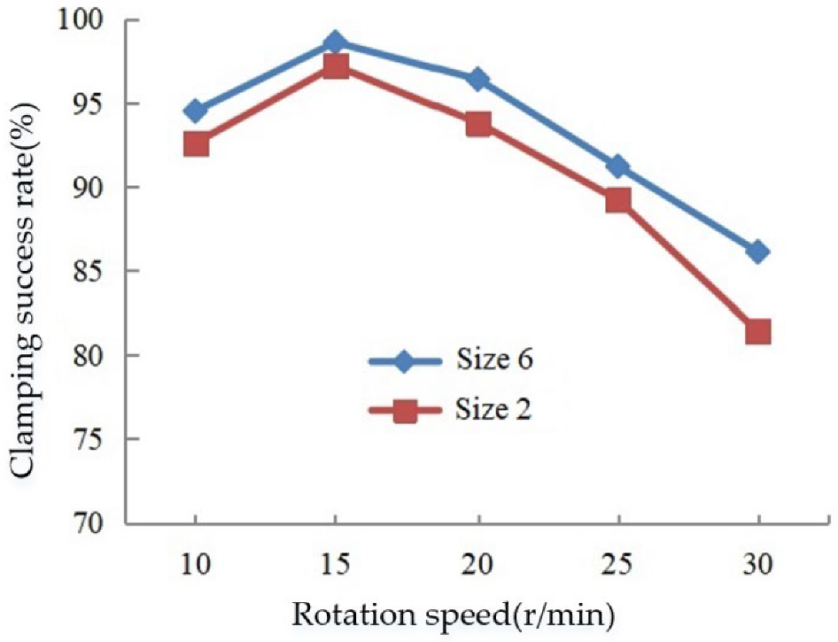
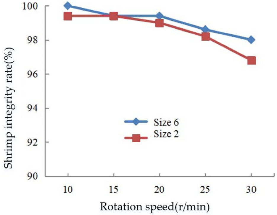
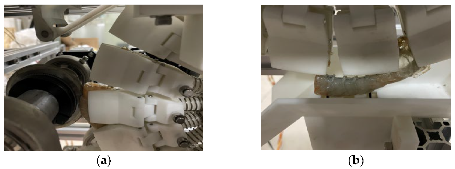
Figure 22 shows the shrimp clamping effect of the clamping mechanism during the test. After the shrimp was pressed by the clamping plate, several clamping units applied clamping force to different parts of the shrimp to achieve segmented clamping. The test data was processed by using the calculation method of the test index. Figure 23 and Figure 24 show the test results.
According to the line chart between the clamping success rate and the rotation speed in Figure 23, the clamping success rate of the two sizes of shrimp was similar: as the rotation speed of the turntable increased, the clamping success first increased and then decreased, and the clamping success rate reached the maximum when the rotation speed was 15 r/min. In addition, according to the test process, the rotation speed was close to the theoretical minimum value when the rotation speed was 10 r/min. The low rotation speed made the spacing between adjacent shrimps too small after feeding, which on occasion led to the situation where the head of the front shrimp and the tail of the rear shrimp shared a clamping plate. This resulted in unstable clamping of the tail of the rear shrimp, and some rear shrimps fell during the stress process in the subsequent peeling process. After the rotation speed exceeded 15 r/min, the increase in the rotation speed increased the centrifugal effect on the shrimp before being clamped. This affected the stable clamping of the shrimps and increased the probability of falling off during the subsequent peeling, and even when the rotation speed was too high, the shrimps fell off before reaching the clamping position. Therefore, too high a speed was not conducive to the stability of clamping. On the whole, the clamping success rate was at an optimal level when the rotation speed of the turntable was 10–20 r/min.
According to the line chart between the shrimp integrity rate and the rotation speed in Figure 24, the clamping success rate of the two sizes of shrimp was similar: as the rotation speed of the turntable increased, the shrimp integrity rate showed a gradual downward trend. For size 6 and size 2 shrimps, the shrimp integrity rate was no less than 99% when the rotation speed did not exceed 20 r/min. Combined with the damage of shrimps during the test, it could be seen that the damaged shrimps belonged to the category of unclamped shrimps, and they all occurred in the position of the pressing plate. When the rotation speed was high, the shrimps on the turntable experienced centrifugal force. When the shrimps moved to the pressing plate, the clamping unit started to shrink and to actively clamp, and the shrimps were squeezed out due to their unstable posture. The extruded shrimps were squeezed and collided with the pressing plate, causing damage to the shell and shrimp meat. Therefore, a small number of shrimps were damaged if the speed was too high. When the rotation speed of the turntable was 10–20 r/min, the shrimp integrity rate was at a better level.
According to the analysis of the test results of the shrimp clamping mechanism, the optimal rotation speed range of the segmented clamping mechanism was 10–20 r/min. Within this rotation speed range, the clamping success rate of the clamping mechanism exceeded 92%, and the shrimp integrity rate was no less than 99%.

3.2.2. Comparative Test Results and Analysis

The index results of the segmented clamping mechanism and turntable fixture clamping mechanism are obtained by processing the comparative test data, as shown in Table 1.
It can be seen from the data in Table 1 that under the conditions of equal interval feeding and indefinite interval feeding, the clamping success rate of the segmented clamping mechanism was more than 97%, and the clamping integrity rate was more than 98%. There was no significant change in the test indicators, and both of them remain at a high level. Therefore, the feeding interval of shrimps had no effect on the clamping of the segmented clamping mechanism. Under the condition of equal interval feeding, the success rate of clamping and the shrimp integrity rate of the clamping turntable clamping mechanism were above 98%, and the clamping effect was good. However, under the condition of indefinite interval feeding, the success rate of clamping was lower than 79%, which significantly decreased the index. At the same time, the integrity rate of the shrimp was also reduced to a certain extent compared with that of regular interval feeding. Therefore, the feeding mode with variable intervals has a great influence on the clamping effect of the rotary clamping mechanism.
In the case of equal interval feeding, there was no significant difference between the segmented clamping mechanism and the turntable clamping mechanism in the two indicators (success rate of clamping and integrity rate of shrimp). However, in the case of variable interval feeding, the clamping success rate of the segmented clamping mechanism was obviously better than that of the turntable clamping mechanism. Since the segmented clamping mechanism adopted the design idea of segmented clamping and unitized the circumferential arrangement, any position on its circumference was suitable for clamping the shrimp, so it could adapt to the feeding conditions at variable intervals. By contrast, the turntable fixture clamping mechanism adopted the working principle of station type, and four fixtures formed a rotation cycle. When the fed shrimp were exactly matched with the passed clamp, the clamp could stably clamp the prawns. Therefore, the turntable fixture clamping mechanism needed to feed shrimp at a fixed time interval and a fixed position. During the test, the feeding at irregular intervals resulted in some shrimps not matching with the fixture, and some shrimps not being clamped, which led to their falling and becoming damage.
According to the above analysis, the segmented clamping mechanism had a stronger adaptability than the turntable clamping mechanism, and had a better clamping effect under the condition of variable interval feeding.

3.2.3. Performance Test Results and Analysis

With two shrimp specifications as the test object, the performance test results of the shrimp directional peeling test device are shown in the Table 2.
Figure 25 records the back opening and kernel removal of shrimp. The shrimp shelling process was successfully completed under the clamping of the segmented clamping mechanism, indicating that the clamping of the segmented clamping mechanism on the shrimp was beneficial to each shelling process. It can be seen from Table 2 that the success rate of shrimp directional shelling test device for No. 2 and No. 6 shrimp reaches more than 91%, and the processing capacity reaches 2420–2560 pcs/h. The success rate of shelling reached a high level, which indicates that the test device could realize the processes of shrimp clamping, back opening, removal of intestines and kernel extraction, and the segmented clamping mechanism and shelling mechanism formed a good cooperation. According to actual survey results, the efficiency of a skilled worker’s manual shelling is generally 700~1200 pcs/h. Compared with manual shelling, the processing capacity of this directional shelling device was more than twice that of manual shelling. Therefore, the segmented clamping mechanism is capable of practical application and can create stable clamping conditions for shrimp shelling.

4. Conclusions

(1) To solve the problem of difficult clamping caused by the uncertainty of the shrimp position after orientation, a segmented shrimp clamping method was proposed. According to the theoretical analysis, the clamping stability was improved by reducing the length of clamps and increasing the number of fixtures for holding the shrimps. The clamping units were evenly distributed on the circumference by means of segmented clamping and multi-point force application. Multiple continuous clamping units could freely form a fixture according to the length and position of the shrimp, and adapt to the changes in the shape of the shrimp and the uncertainty of the clamping position to achieve stable clamping of the shrimp. The segmented shrimp clamping method facilitated the process of back cutting, deveining and peeling of shrimps. During the implementation of the method, it was found that the number of clamping units needed to be increased to reduce the pressure on the shrimp meat.
(2) A segmented shrimp clamping mechanism was designed by using the segmented shrimp clamping method. The mechanism was mainly composed of a clamping unit, a turntable and an arc track, which realized the directional clamping, conveying and discharging of shrimps. According to the characteristics of the sectional profile of the shrimp, an adaptive clamping surface was designed by applying multi-point force, and the profile curve model of the clamping surface was established. According to structural simplification and analysis of the clamping unit, the kinematics and mechanical equations of the clamping unit were established. The compression stroke of the spring during the movement of the clamping unit was 4.3 mm, the spring length was 35 mm, and the spring elastic coefficient was 0.49 N/mm.
(3) The 3D model of the shrimp was established using 3D scanning technology, and the movement process of the clamping mechanism was dynamically simulated by means of the ADAMS software. According to the simulation results, the clamping unit could complete the rotation around the turntable and the opening and closing along the radial direction, and the maximum contact force with the shrimp in the Z direction was 9.3 N. The clamping mechanism realized stable clamping of shrimps, no shrimps fell off during clamping, and the shrimps were not damaged by the clamping force.
(4) A shrimp clamping test bench was built, and a single-factor test was carried out on the influence of the rotation speed of the clamping turntable on the clamping success rate and the shrimp integrity rate. According to the test results, the optimal speed range of the segmented clamping mechanism was 10–20 r/min. Within this rotation speed range, the clamping success rate of the clamping mechanism exceeded 92%, and the shrimp integrity rate was no less than 99%. The results showed that the clamping success rate of the segmented clamping mechanism was more than 97% and the clamping integrity rate was more than 98% under the conditions of equal interval feeding and indefinite interval feeding. Compared with the rotary clamping mechanism, the segmented clamping mechanism had stronger adaptability and better clamping effect under the condition of feeding at variable intervals. The performance test of the shrimp directional peeling test device showed that the success rate of shelling of the shrimp directional shelling test device was more than 91%, and the processing capacity was 2420–2560 pcs/h. In conclusion, the segmented clamping mechanism is capable of practical application and can create stable clamping conditions for shrimp peeling.

Author Contributions

Conceptualization, S.X. and X.F.; methodology, S.X. and Q.L.; software, S.X. and S.B.; validation, S.X.; formal analysis, J.L. and S.X.; investigation, L.G. and Y.F.; resources, J.L.; data curation, Q.L.; writing—original draft preparation, S.X.; writing—review and editing, J.L. and Q.L.; visualization, Y.F.; supervision, X.F.; project administration, Q.L.; funding acquisition, L.G. All authors have read and agreed to the published version of the manuscript.

Funding

This work was mainly supported by Special Project of 2022 Rural Revitalization Strategy in Guangdong, China-Research and development of intelligent equipment for aquatic product sorting and seed sorting (YCN[2022]No.92) and National Key R&D Program of China (2018YFD0700900).

Institutional Review Board Statement

Not applicable.

Data Availability Statement

Data are contained within the article. The data presented in this study can be requested from the authors.

Conflicts of Interest

The authors declare no conflict of interest.

References

  1. Wang, J.; Che, B.; Sun, C.; Zhang, H.Q.; Chen, T.G.; Jin, H.T. Cost-benefit analysis of different culture modes of Penaeus vannamei in China. Chin. Fish. Econ. 2018, 36, 70–76. [Google Scholar]
  2. Teng, Y.; Bi, G.D.; Yu, A.M.; Wang, C.L. Overview processing utilization and industrial development of Litopenaeus vannamei. J. Food Saf. Qual. 2021, 12, 5727–5733. [Google Scholar]
  3. Hao, S.X.; Deng, J.C.; Li, L.H.; Shi, H.; Yang, X.Q.; Huang, H.; Wei, Y.; Qi, B. Nutritional components and safety analysis of shrimp muscle and processing by-products. Sci. Technol. Food Ind. 2012, 33, 337–339+365. [Google Scholar]
  4. Li, Z.Y. The Influential Factors and Countermeasures for Guangdong Province building the Penaeus vannamei Boone Aquaculture Insurance; Jimei University: Xiamen, China, 2015. [Google Scholar]
  5. Zhao, L.T.; Xi, M.J.; Wang, W.; Chu, X.; Zhao, X.; Yuan, Y. A review of technology development process of a typical shrimp peeling machine. J. Adv. Mech. Des. Syst. Manuf. 2015, 9, 1–9. [Google Scholar] [CrossRef] [Green Version]
  6. Ye, K.; Ma, J.Y.; Gong, L.; Zhang, L.; Zhao, X.; Xiao, B. Roller-type Shrimp Sheller Shelling Technology and Optimal Shelling Rate Test of Penaeus vannamei. Mod. Agric. Equip. 2020, 41, 73–77. [Google Scholar]
  7. Yi, J.G.; Ma, J.Y.; Wang, Z.H.; Zhang, X.H.; Yang, S.H. Status and Development of Shrimp Processing Equipment. Mod. Agric. Equip. 2020, 41, 2–11. [Google Scholar]
  8. Ouyang, J.; Shen, J.; Zheng, X.W.; Huang, Y.X.; Xu, H. Research and application status and development tendency of aquatic products processing equipment. Fish. Mod. 2017, 44, 73–78. [Google Scholar]
  9. Jonsson, G. Shrimp Tray with Visual and Tactile Shrimp Sensing Means. U.S. Patent US5435775A, 25 June 1995. [Google Scholar]
  10. Jonsson, G. Method of Cleaning Shrimp. U.S. Patent US2784450A, 12 March 1957. [Google Scholar]
  11. Jonsson, G. Shrimp Cleaning Machine. U.S. Patent US2850761A, 9 September 1958. [Google Scholar]
  12. Zhang, X.H.; Wang, L.G.; Wang, Z.H.; Yi, J.G.; Yang, S.H.; Wang, W. A Belt Type Prawn Back Opening Device. China Patent CN105767115B, 15 December 2017. [Google Scholar]
  13. Zhang, X.H.; Wang, L.G.; Yi, J.G.; Wang, Z.H.; Wang, J. Design and experiment of shrimp backside cutting machine formed by belt clamping and conveying. Trans. Chin. Soc. Agric. Eng. 2017, 33, 284–291. [Google Scholar]
  14. Jonsson, G. Shrimp Processing Machine and Method. U.S. Patent US3566437A, 2 March 1971. [Google Scholar]
  15. Jonsson, G. Machine for Cleaning Shrimp. U.S. Patent US3214789A, 2 November 1965. [Google Scholar]
  16. Keith, J.T.; Betts, E.D.; Dancy, M.J.; Pershinske, J.E. Semi-Automatic Shrimp Peeling Machine. U.S. Patent US5522764A, 4 July 1996. [Google Scholar]
  17. Keith, J.T. Shrimp Processing Machine and Method of Processing Shrimp. U.S. Patent US06485363B2, 26 November 2002. [Google Scholar]
  18. Betts, E.D. Shrimp Processing Machine Having Improved Cutting Structure. U.S. Patent US4414709A, 15 November 1983. [Google Scholar]
  19. Keith, J.T.; Betts, E.D.; Dancy, M.J. Semi-Automatic Shrimp Peeling Machine. U.S. Patent US5366405A, 22 November 1994. [Google Scholar]
  20. Zhang, J.J.; Zhang, L.Q.; Zhao, X.H.; Luo, Q.J.; Huang, P.S. Research and design of shrimp shelling equipment. Mod. Agric. Equip. 2011, 7, 50–52. [Google Scholar]
  21. Liu, J. A Study of the Dynamic of Slider-crank Mechanism. J. Shanghai Dianji Univ. 2006, 9, 24–28. [Google Scholar]
  22. Liu, S.L.; Hu, P.H. Akinetic characteristic analysis of slider- crank mechanism and simulation realization. Mach. Des. Manuf. 2008, 5, 79–80. [Google Scholar]
  23. Zhou, L.; Chen, P. Research on development of reverse engineering. Comput. Eng. Des. 2004, 1658–1660+1666. [Google Scholar]
  24. Gong, W.F.; Huang, M.F. Application and Research of Reverse Engineering Technology. Mach. Des. Manuf. 2013, 110–112. [Google Scholar]
  25. Xiong, S.; Zhao, B.; Hu, X.L.; Li, J.; Zhou, L.M.; Fang, X.F. Design and Experiment on Prawn Single Separation Device. Trans. Chin. Soc. Agric. Mach. 2020, 51, 357–365. [Google Scholar]
  26. Liu, R.; Liu, Z.J.; Liu, L.J.; Li, Y.H. Design and Experiment of Corn High Speed Air Suction Seed Metering Device with Disturbance Assisted Seed-Filling. Trans. Chin. Soc. Agric. Mach. 2022, 53, 50–59. [Google Scholar]
  27. Zhang, X.J.; Zhang, Y.H.; Shi, Z.L.; Ma, S.T.; Huang, S.; Cheng, J.P. Optimization and Experiment of Oil Sunflower Combined Harvester Cleaning Device. Trans. Chin. Soc. Agric. Mach. 2022, 53, 103–113. [Google Scholar]
  28. Zhang, X.H.; Zhao, Q.L.; Wang, Z.H.; Yi, J.G.; Wang, J. Parameter optimization experiment of adjustable five rollers shrimp peeling machine. Trans. Chin. Soc. Agric. Eng. 2016, 32, 247–254. [Google Scholar]
  29. Li, L.L.; He, X.K.; Song, J.L.; Liu, Y.; Wang, Z.C.; Li, J.Y.; Jia, X.M.; Liu, Z.X. Comparative experiment on profile variable rate spray and conventional air assisted spray in orchards. Trans. Chin. Soc. Agric. Eng. 2017, 33, 56–63. [Google Scholar]
  30. Zhang, J.X.; Zhang, L.; Liu, X.F.; Jiang, Y.X.; Wang, J.K. Mechanical analysis and contrast experiment on collecting residual plastic film with different side-film shovels. Trans. Chin. Soc. Agric. Eng. 2017, 33, 10–15. [Google Scholar]
  31. Yi, J.J.; Ding, G.W.; Hu, H.; Dong, P.; Li, Y.; Liao, X.J.; Zhang, Y. Comparison of shucking techniques for white shrimp and its effect on quality of peeled shrimp. Trans. Chin. Soc. Agric. Eng. 2012, 28, 287–292. [Google Scholar]
  32. Du, Y.F.; Mao, E.R.; Song, Z.H.; Zhu, Z.X.; Gao, J.M. Simulation on Corn Plants in Harvesting Process Based on ADAMS. Trans. Chin. Soc. Agric. Mach. 2012, 43, 106–111. [Google Scholar]
  33. Wang, S.Y.; Hu, Z.C.; Peng, B.L.; Wu, H.C.; Gu, F.W.; Wang, H.O. Simulation of Auto-follow Row Detection Mechanism in Beet Harvester Based on ADAMS. Trans. Chin. Soc. Agric. Mach. 2013, 44, 62–67. [Google Scholar]
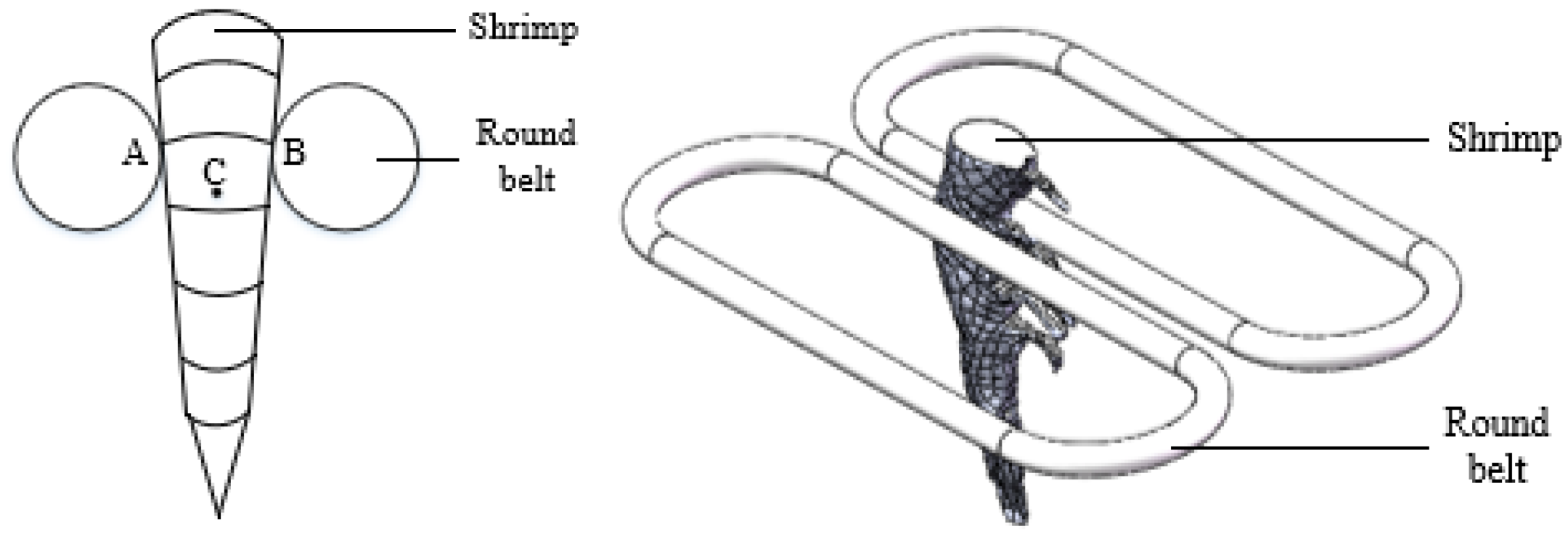
Figure 1. Symmetrically supported head-to-tail orientation: A is the left support point; B is the right support point; and C is the center of gravity of shrimp.
Agriculture 12 02118 g001
Figure 2. Position of the shrimp after orientation.
Agriculture 12 02118 g002
Figure 3. Cycle clamping fixture.
Agriculture 12 02118 g003
Figure 4. Segmented clamping.
Agriculture 12 02118 g004
Figure 5. Schematic diagram of segmented shrimp clamping method.
Agriculture 12 02118 g005
Figure 6. Force analysis of shrimps during back cutting or deveining.
Agriculture 12 02118 g006
Figure 7. Segmented shrimp clamping mechanism.
Agriculture 12 02118 g007
Figure 8. Structure of the clamping unit: (a) open state, and (b) closed state.
Agriculture 12 02118 g008
Figure 9. Adaptive clamping surface: (a) double clamping surface open state, and (b) clamping surface structure.
Agriculture 12 02118 g009
Figure 10. Coordinates of comprehensive clamping curve.
Agriculture 12 02118 g010
Figure 11. Force analysis of clamping unit.
Agriculture 12 02118 g011
Figure 12. Track structure.
Agriculture 12 02118 g012
Figure 13. Profile of track surface.
Agriculture 12 02118 g013
Figure 14. The 3D scanner.
Agriculture 12 02118 g014
Figure 15. The 3D model of shrimp.
Agriculture 12 02118 g015
Figure 16. Simulation model.
Agriculture 12 02118 g016
Figure 17. Shrimp clamping test bench.
Agriculture 12 02118 g017
Figure 18. The fixture turntable clamping mechanism.
Agriculture 12 02118 g018
Figure 19. The shrimp directional peeling test device.
Agriculture 12 02118 g019
Figure 20. Simulation motion process of clamping mechanism.
Agriculture 12 02118 g020
Figure 21. Change curve of contact force of clamping plate in Z direction: (a) front clamping plate, and (b) rear clamping plate.
Agriculture 12 02118 g021aAgriculture 12 02118 g021b
Figure 22. Shrimp clamping process: (a) feeding, (b) start of clamping, and (c) end of clamping.
Agriculture 12 02118 g022
Figure 23. Relationship between clamping success rate and rotation speed.
Agriculture 12 02118 g023
Figure 24. Relationship between shrimp integrity rate and rotation speed.
Agriculture 12 02118 g024
Figure 25. Performance test: (a) open back, and (b) kernel extraction.
Agriculture 12 02118 g025
Table 1. Comparison test results.
Shrimp SpecificationsTest IndexSegmented Clamping MechanismTurntable Fixture Clamping Mechanism
Equal Interval FeedingUnequally Spaced FeedingEqual Interval FeedingUnequally Spaced Feeding
No. 2Clamping success rate/%97.297.299.475
Shrimp integrity rate/%98.899.498.893.3
No. 6Clamping success rate/%98.397.798.878.9
Shrimp integrity rate/%99.499.499.495.6
Table 2. Performance test results.
Shrimp SpecificationsPeeling Success Rate (%)Processing Capacity (pcs/h)
No. 292.52520
93.12490
92.22560
No. 691.52420
91.32460
92.02460
Publisher’s Note: MDPI stays neutral with regard to jurisdictional claims in published maps and institutional affiliations.