Article

Design and Working Parameter Optimization of Pneumatic Reciprocating Seedling-Picking Device of Automatic Transplanter

Jiangsu Provincial Key Laboratory of Hi-Tech Research for Intelligent Agricultural Equipment, Jiangsu University, Zhenjiang 212013, China
*
Author to whom correspondence should be addressed.
Agriculture 2022, 12(12), 1989; https://doi.org/10.3390/agriculture12121989
Submission received: 17 October 2022 / Revised: 10 November 2022 / Accepted: 18 November 2022 / Published: 23 November 2022
(This article belongs to the Section Agricultural Technology)

Abstract

:
To improve the seedling-picking efficiency of the vegetable transplanter and reduce the damage rate of the seedling pot, a reciprocating seedling-picking device driven by full air pressure was designed. In this paper, the structure and working principle of the pneumatic seedling-picking device are introduced. Through the mechanical analysis between the seedling-picking claw and the seedling pot, working parameters such as the stroke and driving force of the pneumatic seedling-picking claw clamping cylinder were determined. According to the action sequence of the seedling-picking mechanism, which is horizontally dispersed and longitudinally conveyed, the pneumatic control scheme of the seedling-picking and -dropping system was formulated. The simulation model for the control loop of the longitudinal cylinder was created with AMESim simulation software, and the simulation analysis was carried out. The Box–Behnken response surface design optimization method was used to determine the best operating parameters of the cylinder. The optimized peak value of shock vibration at the end of the cylinder was optimized from −65.64 mm·s−2 to 35.41 mm·s−2, proving that the optimization of pneumatic working parameters has a positive effect on the success rate of seedling picking. The bench test of the seedling-picking mechanism was conducted on 72-hole plug seedlings with two picking frequencies of 120 plants·min−1 and 144 plants·min−1, respectively, and the average seedling leakage rate, seedling damage rate, and seedling pot damage rate at different picking frequencies were counted. The experimental results show that under the two seedling-picking frequencies, the average success rate of seedling picking and throwing after optimization is increased from 96.4% and 92.4% to 97.9% and 95.3%, respectively. This is in line with the requirements of high-speed seedling picking and confirms the rationality of the seedling-picking mechanism design.

1. Introduction

The technique of transplanting vegetables has been widely promoted due to its advantages such as avoiding natural disasters and improving the survival rate of seedlings [1]. At present, semi-automatic transplanting machines are mainly used in China. Picking and throwing seedlings must be performed manually, which not only has high costs regarding labor but also has the disadvantage that the speed is limited and manual labor is easily fatigued, which limits the improvement of transplanting efficiency [2]. Therefore, it is of great significance to develop a high-speed seedling-picking device with a reasonable structure to improve the operation efficiency of vegetable transplanters, reduce labor intensity, and promote the development of the vegetable industry [3,4].
The automatic seedling-picking mechanism developed in Europe and the United States mostly adopts electrical joint control, with many auxiliary devices and a huge mechanism, and requires a special seedling tray to achieve automatic transplanting, which is not suitable for the current situation of tray seedling raising in China [5,6,7,8]. Most of the automatic seedling-picking mechanisms developed in Japan are purely mechanically controlled, using different combinations of mechanisms to realize the automatic seedling-picking function [9,10,11], but the complex structure and high requirements for seedling quality have limited the application in China.
In recent years, in order to accelerate the process of agricultural modernization in China, some research institutes have invested in the development of automatic seedling-picking mechanisms. Otherwise, the insert-clamping seedling-picking method based on the principle of upward seedling picking is stable and reliable and can be adapted to the existing domestic agronomy of seedling cultivation in seedling trays. Therefore, domestic scholars have combined mechanical, electrical, and gas integration technology and designed and developed a variety of seedling-picking devices that are inserted into the pot and clamped. Among them, some scholars used a plane multi-bar mechanism to drive the seedling-picking manipulator to realize automatic seedling picking. This seedling-picking device is not only complicated in structure but also not very efficient in operation [8,12,13]. Sun et al. [14] designed a planetary gear train linkage mechanism, inserting the seedling end effector into the substrate at a certain angle and placing the pot seedlings upright into the planting device to complete the entire transplanting process. Li et al. [15] proposed a slide-type automatic seedling-picking mechanism driven by the planetary gear train. The two kinds of rotating planetary system seedling-picking mechanisms are both high-speed plane composite operations with large inertial force, and seedling picking is unstable. Ye et al. [16,17] proposed an eccentric non-circular gear planetary automatic seedling-picking mechanism, which solves the problems of complex structure and low efficiency of transplanters to a certain extent. Although these seedling-picking mechanisms have realized the automation of picking seedlings to a certain extent, due to the complex structure and the difficulty in planning the seedling-picking trajectory, the mechanism has not been practically applied, with low seedling-picking efficiency, a low seedling-picking success rate, and poor stability. The frequency of picking seedlings is mostly 40~90 plants·min−1 [18,19,20]. When the frequency of picking seedlings is greater than 70 plants·min−1, the variable-speed rotation or swing of the mechanism causes the impact vibration and inertial force of the seedling needles to increase significantly, while the damage rate of the pot body increases, the stability of seedling clamping decreases, and seedling-picking failures such as seedling shedding or seedling throwing occur. This phenomenon led to a decrease in the success rate of seedling harvesting [21]. Ye, Yu et al. carried out kinetic research and optimization improvements on similar seedling-picking mechanisms [12,22,23], and the impact vibration and inertial force were slightly improved, but when the seedling-picking speed increased, there was still a problem regarding the end effector of picking seedlings causing great damage to the seedling pot due to vibration [24,25]. Han et al. [26] designed a guide-rail-based manipulator for seedling picking, in which the manipulator flipping cylinder and positioning cylinder control the posture change of the manipulator along the guide rail at the seedling-picking position and the seedling-throwing position. Some scholars developed a linear sliding-type pneumatic seedling-picking mechanism, which uses a cylinder to drive the seedling-picking manipulator to pick up seedlings, and the seedling-picking manipulator only grabs normal plug seedlings for transplanting [27,28].
Compared with mechanical transmissions such as connecting rods and planetary gear trains, pneumatic transmission has the characteristics of rapid action, fast response, and can realize large-stroke transmission, etc., and has been used in the development of seedling-picking mechanisms. The existing pneumatic seedling-picking mechanism mainly uses the air cylinder as the executive element, which is driven by air pressure to complete the time sequence control of the specified action. The motion characteristics of the air cylinder are not analyzed. For this reason, this paper proposed a pneumatic reciprocating seedling-picking device with multiple claws in parallel for the whole row, analyzed the dynamic characteristics of the pneumatic seedling-picking mechanism, and optimized the working parameters of the cylinder through AMESim simulation software. Finally, 72-hole plug seedlings were used as the test object to verify the feasibility of the high-speed seedling-picking device, and this paper provides a reference for the development of a lightweight and simple high-speed seedling-picking device.

2. Device Structure and Working Principle

2.1. Seedling Tray Specifications

The size of the seedling tray matching the seedling-picking mechanism was a 72-hole (12 × 6) standard seedling tray, and the size of the tray was 540 × 280 × 40 (mm), as shown in Figure 1. Each hole had an inverted cone shape and an inclination angle α = 79°, and the center-to-center distance between the holes was 43 mm.

2.2. Structure of the Device

The automatic seedling-picking mechanism is the core working part of the transplanter. The pneumatically reciprocating seedling-picking device with the cylinder linear drive mechanism replaced the existing turning mechanism, as shown in Figure 2. The seedling-picking mechanism was mainly composed of the seedling-picking frame, linear slide rail, seedling-picking mounting plate, seedling-picking execution component, longitudinal driving cylinder, and horizontal driving cylinder. Among them, the seedling-picking execution component was installed on the seedling-picking installation plate through the horizontal linear slide rail, which can realize the actions of combining seedling picking and dispersal of the seedling casting through the drive of the horizontal cylinder. At the same time, the seedling-picking installation plate was installed on the seedling-picking frame by a longitudinal linear slide, and the movement from the seedling-picking position to the seedling-throwing position was realized by the longitudinal cylinder.
The seedling-picking executive component is composed of a lifting cylinder, clamping cylinder, seedling-picking claw, and mounting plate. The object of the operation is 72-hole seedlings tray. In the construction, the method of picking seedlings at fixed points was used. In order to avoid the phenomenon of picking seedlings from adjacent holes, the method of picking seedlings at intervals was further adopted, and the seedling claws were placed at equal intervals of 86 mm, so as not to interfere with each other when picking seedlings.

2.3. Working Principle

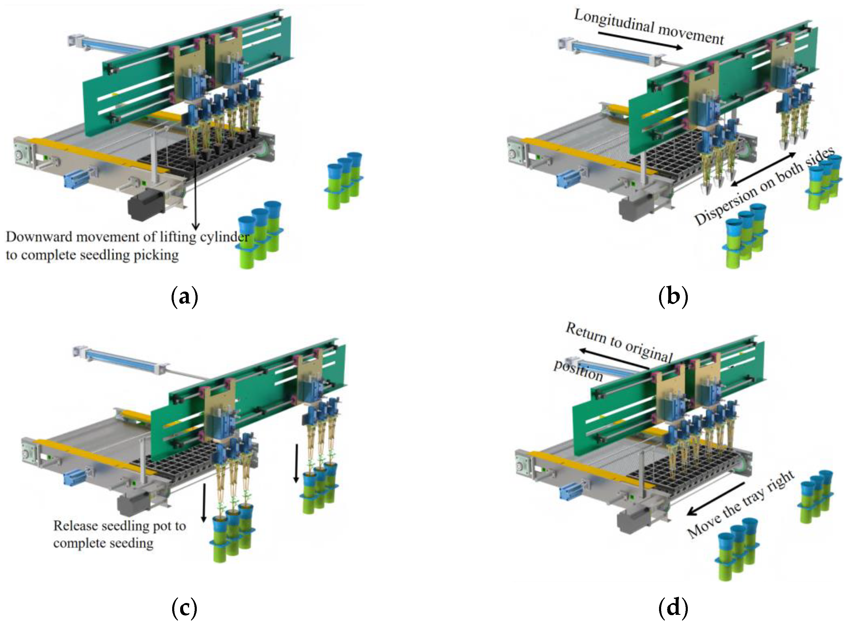
In order to solve the problem of damage to the seedling pot and the difficulty of proving the efficiency of seedling picking by the overturning method, a linear reciprocating method of picking and throwing seedlings was proposed, and the working principle is shown in Figure 3:
  • The seedling tray is placed on the conveying device and the stepping motor rotates and drives the chain stopper forward to push the tray for longitudinal conveying. When the sensor recognizes the seedling tray, the stepping motor stops, and the stopping position is the position point for picking seedlings.
  • As shown in Figure 3a, when the seedling tray reaches the seedling-picking position, the seedling-picking execution component installed on the seedling-picking mounting plate will pick up the seedlings. The air cylinder drives the seedling-fetching claws to grip the pot body. When the lifting cylinder triggers the magnetic switch at the lower limit of the cylinder, it starts to move upward. At this time, the seedling pot is driven from the seedling tray by the seedling fetching claws, and the seedling removal is completed.
  • The two sides of the seedling-picking plate are connected to the linear slide rails installed on the seedling-picking frame, which can achieve straightforward sliding of the seedling-picking mechanism. The horizontal cylinder drives the end execution components of the seedlings to complete the dispersing action and transports the seedling pots to the seedling-throwing position and waits for the seedlings to be thrown, as shown in Figure 3b.
  • When the seedling-throwing command is triggered, the lifting cylinder moves downwards, and at the same time, the clamping cylinder moves in the opposite direction to release the seedling pot, and the seedling pot falls into the seedling guide tube by its own weight to complete the seedling throwing action.
  • As shown in Figure 3d, the seedling tray conveying device is moved to the right by a distance of one hole spacing (43 mm), and the combined action of the longitudinal driving cylinder and the horizontal driving cylinder returns to the position of picking seedlings, ready to complete the next cycle of seedling picking and throwing.

3. Design and Analysis of Key Components

3.1. Design of Seedling-Picking Claw

In order to improve the operation efficiency and quality of the seedling-picking mechanism, a new type of seedling-picking needle clamp effector was developed based on pneumatic technology.

3.1.1. Principle of Clamping Seedling

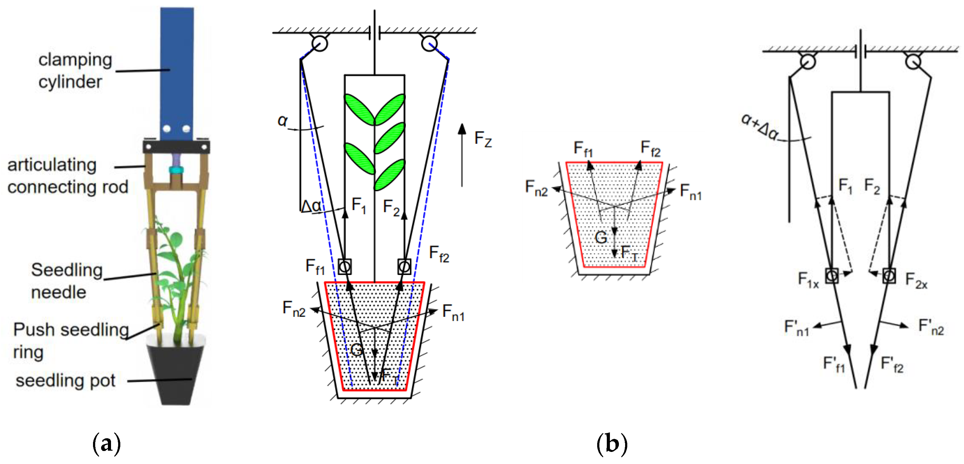
Figure 4a shows the design of the finger-clip-type seedling-picking claw. When picking seedlings, the seedling claws are located above the seedlings on the seedling tray, and the push rod of the clamping cylinder is in an extended state. The lifting cylinder runs down, and the seedling claws are driven by the lifting cylinder to push the seedling needles into the pot body. At the same time, the push rod of the clamping cylinder shrinks, causing the seedling push ring to retract, and the seedling needles rely on the hinge mechanism to move toward the middle. The resulting tightening force clamps the seedling pot, thereby completing the clamping action of the seedling pot. When the seedling claws are fully inserted and clamped to the pot, the seedling claws stay brief. We then take the seedling claws and move the seedling pot to the top of the seedling tray driven by the lifting cylinder. After moving the seedling pot to the throwing seedling position, the cylinder push rod is clamped to extend, and the push rod is driven by the cylinder push rod. The seedlings are pushed off from the needles. The actions of picking seedlings, carrying seedlings, and throwing seedlings are completed in one exercise cycle.

3.1.2. Mechanical Analysis of Seedling Claws and Seedling Pot

Regarding the moment the seedling claws grip the seedling pot and start to move upward, the force analysis is shown in Figure 4b. The seedling needle is inserted into the seedling pot at an angle of α. To prevent the seedling needle from being inserted into the side wall of the seedling tray, α is determined by the taper of the hole, α = 11°. h is the height of the seedling pot, which is determined by the depth of the hole, h = 40 mm. L is the depth of the seedling needle inserted into the pot. According to a previous study of our research group on the distribution of pot roots in the vertical direction, the pot has the lowest root density at a depth of 2/3. To prevent the pot from breaking and being damaged at this point, the insertion depth should exceed the fracture area, L = 35 mm.
First, the force of the seedling pot was analyzed. We ensured the friction force generated by seedling picking against the pot overcomes the adhesion force F T generated by the hole of the pot and the gravity G of the pot. Formulas are listed according to the principle of force balance
{ F n 1 sin ( α + Δ α ) + F f 2 cos ( α + Δ α ) + F n 2 sin ( α + Δ α ) + F f 1 cos ( α + Δ α ) F T + G F n 1 cos ( α + Δ α ) + F f 2 sin ( α + Δ α ) = F n 2 cos ( α + Δ α ) + F f 1 sin ( α + Δ α ) F f 1 = F f 2 = μ F n 1 = μ F n 2
where F n 1 and F n 2 are the positive pressures of the seedlings against the pot body, N; F f 1 and F f 2 are the frictional forces between the clamping needle and the pot, N; α is the angle formed by the seedling needle and the vertical direction, (°); μ is the friction factor between the pot and the seedling needle, where 0.49–0.54; G is the weight of the pot body, N; F T is the adhesion force of the hole to the pot body, which measured that the adhesion of cucumber, tomato, and other tray seedlings ranges from 0.97 to 2.93 N [29].
Then the force of the seedling needle was analyzed. The seedling needle is subjected to the counter force of the pot and the upward force F 1 and F 2 of the seedling pushing ring F 1 and F 2 are produced by the clamping cylinder retracting the piston rod. Formulas are listed according to the principle of force balance
{ F 1 x = F n 1 = F n 1 F 2 x = F n 2 = F n 2 F 1 x = F 1 · sin ( α + Δ α ) F 2 x = F 2 · sin ( α + Δ α )
where F 1 and F 2 are the lifting force generated by the clamping cylinder, N; F 1 x is the F 1 component force perpendicular to the direction of the seedling needle, N; F 2 x is the F 2 component force perpendicular to the direction of the seedling needle, N.
Assuming that the seedling pot is a homogeneous material structure, the effects of F n 1 and F n 2 are the same. Derived from Formula (1), it can be stated that
F n 1 = F n 2 F T + G 2 ( sin ( α + Δ α ) + μ cos ( α + Δ α ) ) = 2.15   N
The swing angle Δ α is related to the amount of clamping deformation, if the swing angle is too large, the pot body will be damaged. Therefore, the angle increment can be ignored when calculating the formula.
The lifting force of the clamping cylinder in the seedling claw corresponds to the following formula (derived from Formula (2))
F o = F 1 + F 2 = 2 F n 1 sin ( α + Δ α ) = 22.5   N
It can be seen that the clamping cylinder only needs to provide a force greater than 22.5 N to overcome the adhesion force during seedling removal. The output force of the clamping cylinder is determined by the cylinder diameter and the working air pressure, which satisfies the formula
F o = P π ( D 2 d 2 ) 4
where F o is the output force of the clamping cylinder, N; D is the inner diameter of the cylinder, mm; and d is the diameter of the piston rod, mm.
According to the primary selection range of working air pressure of 0.3–0.5 MPa, the inner diameter of the clamping cylinder is 16 mm and the diameter of the piston rod is 6 mm. According to the analysis of the structural parameters of the seedling claw, the stroke of the clamping cylinder is equal to the stroke of the push ring, which is 35 mm. Therefore, the cylinder of type MD 16 × 40 was selected as the clamping cylinder. The lifting cylinder overcomes the weight of the seedling component and completes the insertion depth of the seedling needle and the lifting height of the seedling pot. According to the above analysis procedure, the TCL 25 × 50-S cylinder with a stroke of 50 mm was selected as the lifting cylinder.

3.2. Selection and Calculation of Pneumatic Components of Seedling-Picking Mechanism

According to the design requirement of the maximum seedling-picking speed of 144 plants·min−1, the total cycle of picking and throwing is 2.5 s. After deducting the time for picking and throwing seedlings, the time from the position of picking seedlings to the position of throwing seedlings must be within 1 s. According to the requirements of automatic seedling picking in the working environment of the transplanter, the working pressure of the cylinder is 0.4 MPa. The working stroke of the longitudinal cylinder is 400 mm, depending on the distance between the position of picking seedlings and the position of throwing seedlings. The horizontal cylinder is determined by the row spacing, calculated by the design distance of 400 mm row spacing, and the horizontal cylinder stroke is 200 mm. In order to ensure the smooth operation of the seedling-picking process, the average running speed of the cylinder was set to 400 mm·s−1, so the running time of the horizontal cylinder and the running time of the longitudinal cylinder are 0.5 s and 1.0 s, respectively. Based on the determined parameters such as stroke and time, the required acceleration can be derived from Equation (6), and the inner diameter of the cylinder can be derived from Equation (7), which provides a basis for the selection of horizontal and vertical cylinders.
L = 1 2 a t 2
{ F = P π D 2 / 4 η F μ m g = m a
where L is the stroke of the cylinder, mm; a is the operating acceleration of the cylinder, m s−2; t is the running time of the cylinder, second; F is the theoretical output force of the cylinder, N; η is the cylinder load rate, which refers to the ratio of the actual output force of the cylinder to the theoretical output force, which is determined by the working state, 0.65; μ is the friction factor between the linear slide rail and the seedling-picking mechanism; m is the mass of the seedling-picking assembly, kg; g is the acceleration of gravity; P is the working air pressure, MPa; D is the inner diameter of the cylinder, mm.
Regarding the parameters in Table 1 to query the pneumatic component selection manual, the model for the horizontal cylinder is MA 16 × 200-SCALB and the model for the longitudinal cylinder is SC 32 × 400-S.

3.3. Design of Pneumatic System

As shown in Figure 5, the pneumatic components in the pneumatic seedling-picking mechanism consist of two lifting cylinders A, six clamping cylinders B1 and B2, two transverse driving cylinders C, and one longitudinal driving cylinder D. The lifting cylinder is controlled by solenoid valve S1, and the speed is adjusted by the throttle valves J1 and J2. Due to the large number of clamping cylinders, the phenomenon of insufficient air supply occurs when the same solenoid valve is used for control. For this reason, the clamping cylinders are divided into two groups, which are controlled by solenoid valves S2 and S3, and throttle valves J3–J6 are used for speed adjustment. The transverse cylinder is controlled by the solenoid valve S4, and the speed is adjusted by the throttle valves J7 and J8. The longitudinal cylinder is controlled by the solenoid valve S5, and the speed is adjusted by the throttle valves J9 and J10. At the same time, a safety valve is added to the exhaust throttle circuit to buffer the back pressure.
We calculated the total air consumption based on the parameters of the cylinder and selected the appropriate air compressor according to the total air consumption. The average air consumption for one round trip of each cylinder was calculated according to Formula (8) [30]. The total air consumption was calculated according to the maximum frequency of picking seedlings, and the speed of picking seedlings was 144 plants·min−1. The calculation results of the air consumption of each cylinder are shown in Table 2.
Q a = π 2 N D 2 L P + 0.1 0.1 × 10 3
where Q a is the average air consumption of the cylinder, L·min−1; N is the operating frequency of the cylinder; D is the inner diameter of the cylinder, cm; L is the stroke of the cylinder, cm; P is the working pressure of the cylinder, MPa.
It can be seen from Table 1 that the total air consumption of the seedling feeding system is 119.86 L·min−1. In order to ensure the stability of the air source pressure, an air compressor with a volume flow of more than 120 L·min−1 should be selected for the seedling-picking system to provide compressed air.

4. Optimization of Cylinder Working Parameters

4.1. Analysis of Optimization Goals

In the process of high-speed reciprocating motion, the motion state of the driving cylinder, especially the end impact, causes the end effector of seedling picking to produce a large inertial impact at the seedling-throwing position, which affects the stability of the whole seedling-picking mechanism. According to the kinetic energy formula:
E K = 1 2 m v 2
It can be seen that the higher the cylinder running speed and the heavier the load, the greater the kinetic energy that the end needs to release. To reduce the end shock, the cylinder working speed needs to be adjusted.
The differential equation of the pressure on the compression side and the tension side of the cylinder is [31]:
{ k ( p 1 A 1 v R T e ) V 1 q m 1 = d p 1 d t k ( p 2 A 2 v + R T f ) V 2 q m 2 = d p 2 d t
where k is the adiabatic coefficient of the cylinder, of which the value is 1.4; T e is the absolute temperature of the pressure chamber air source, K; p 1 is the absolute pressure of the pressure chamber, pa; V 1 is the pressure chamber volume, m3; q m 1 is the gas flow mass of the pressure chamber, kg·s−1; A 1 is the piston area of the pressure chamber, m2; v is the piston speed, m·s−1. T f is the absolute temperature of the tension chamber gas, K; p 2 is the absolute gas pressure on the tension side, pa; V 2 is the tension chamber volume, m3; q m 2 is the tension chamber gas flow quality, kg·s−1; and A 2 is the effective area of the piston in the tension chamber, m2.
From the formula, it can be concluded that the working speed of the cylinder is related to the air source pressure, the intake gas flow, and the exhaust gas flow. The air source pressure P is a fixed value of 0.4 MPa. Therefore, the main parameter for adjusting the working speed of the cylinder is the flow rate of the intake and exhaust gasses. Specifically, this means that the working speed of the cylinder is controlled by adjusting the opening of the throttle valve J1–J10 in Figure 5, where the opening of the throttle valve is represented by the flow rate coefficient n.
As shown in Table 3, the end impact of the longitudinal cylinder is the most pronounced. Buffer material is installed at the end of the cylinder, which can absorb the kinetic energy impact within a certain range. Using the single-factor test, it can be found that the flow coefficient of the throttle valve of the lifting cylinder and the horizontal cylinder is 0.8 and the specified seedling-picking speed can be realized without causing damage and falling of the seedling pot.
However, due to the long stroke and large load of the longitudinal cylinder, it is impossible to adjust the throttle valve to achieve stable seedling throwing. For this reason, a safety valve that can buffer the back pressure is added to the exhaust throttle circuit. Since the pneumatic transmission system is a nonlinear system it is difficult to optimize and adjust it by theoretical analysis. Therefore, AMESim pneumatic simulation software is used to build a model for simulation analysis, and the response surface analysis method is used to optimize the appropriate working parameters and shock and vibration peak values and verify the rationality of parameter optimization.

4.2. AMESim Simulation Analysis of Longitudinal Cylinder Pneumatic Control Circuit

Using the user-defined module (PCD) in the AMESim pneumatic library, the simulation models of the cylinder, solenoid valve, safety valve, and control circuit for driving the cylinder are established [32], as shown in Figure 6. According to the actual physical parameters of the existing pneumatic components, the simulation environment and load conditions are set, and then simulation experiments are conducted. The simulation parameters are listed in Table 4. The simulation condition is the single action of the cylinder for picking and throwing seedlings.

4.3. Optimization of Aerodynamic Parameters Based on Response Surface Method

Response surface optimization analysis method: Take one or more factors as independent variables, express the corresponding relationship between independent variables and dependent variables in the form of a response surface, and then obtain the optimal result from the response surface curve. In this section, Design-Expert software is used to carry out Box–Behnken response surface design.
(1) Determine the optimization goal.
First of all, it is necessary to ensure the accuracy and stability of the seedlings, and at the same time, reach the seedlings as fast as possible. This means that the goal is to reduce the deformation amount of the seedling-picking executive component and reduce the time for seedlings to be thrown.
(2) Constraints.
The air source pressure, flow coefficient of the speed control valve, and flow coefficient of the safety valve are several important parameters that affect the operation of the cylinder of the seedling-picking mechanism. Equation (11) is the constraint condition of the above parameters:
{ 0.3 p 1 0.5 0.5 n 1 0.9 0.5 n 2 0.9
where p 1 represents the air source pressure, MPa; n 1 represents the flow coefficient of the speed control valve, and its range is generally 0.3–0.9; and n 2 represents the flow coefficient of the safety valve, and its range is generally 0.3–0.9.
(3) Response surface analysis process.
The above constraints are input into Design-Expert, and the Box–Behnken response surface test design is carried out. Based on this, we input 17 sets of simulation parameters into the AMESim high-speed cylinder simulation model established above and then carried out a simulation analysis. The simulation results are shown in Table 5:
According to the data samples in Table 5, the quadratic polynomial regression model of the maximum cylinder speed and the stabilization time consumption is obtained using Design-Expert software.
{ Y 1 = 0.62 + 2.27 p 1 + 0.4 n 1 + 0.4 n 2 0.4 p 1 n 1 1.32 p 1 2 0.17 n 1 2 0.28 n 2 2 Y 2 = 1.40 1.48 p 1 0.01 n 1 0.13 n 2 0.13 p 1 n 1 + 1.13 p 1 2 + 0.03 n 1 2 + 0.09 n 2 2
where Y 1 is the maximum running speed of the cylinder and Y 2 is the time consumption for cylinder stabilization.
According to the results of variance analysis of regression models, P < 0.0001 of the two regression models indicates that the regression models are highly significant. The determination coefficient R2 and the correction determination coefficient of the two models are close to 1, and the coefficient of variation and precision are 0.30%, 0.42% and 57.67, 47.55, respectively, which shows that the regression model for fitting the maximum operating speed of the cylinder and the time consumption of cylinder stability is highly reliable. However, the regression model of the maximum acceleration of the cylinder P = 0.237 > 0.05, indicating that the regression model is not significant, so it will be used as a secondary reference in the subsequent optimization analysis, and the optimal parameters will be determined by comparing the simulation results. Based on the analysis results of the regression model, the 3D response surface of interaction effects of various factors is drawn using Design-Expert 13.0.1 software.
As shown in Figure 7, the main factor affecting the stabilization time of the cylinder t s t is the air source pressure p 1 , while the influence of the speed control valve flow coefficient n 1 is small and the safety valve flow coefficient n 2 has almost no influence. Within the range of constraints, with the decrease in p 1 and n 1 , the time required for cylinder stabilization increases, and the interaction of the individual factors is not significant.
As shown in Figure 8, when n 2 = 0.7 and n 1 is at a high level, the maximum acceleration of the cylinder is positively correlated with the air pressure; when n 2 = 0.7 and p 1 is at a high level, the maximum acceleration of the cylinder is negatively related to the flow coefficient. However, when the flow coefficient n 1 is small, the maximum acceleration of the cylinder first increases and then decreases as the air source pressure increases. This is because the cylinder drives the load to accelerate the movement, and the presence of the inertial force causes the volume of the intake cavity to increase sharply. Due to the low flow coefficient of the speed control valve, the intake air volume cannot fill the intake cavity in time, thereby forming a certain negative pressure, which reduces the pressure of the intake cavity and thus affects the maximum acceleration of the cylinder. This is consistent with the previous analysis results on the dynamic characteristics of the cylinder, which further verifies the accuracy of the simulation results.
(4) Analysis of optimization results.
The objective optimization parameters are set in Design-Expert software. The target parameter settings are shown in Table 6.
Through Design-Expert’s target parameter optimization analysis, several optimization schemes are created, as shown in Table 7. Combined with the optimization objectives, constraints, and optimization results of the response surface test parameters shown in Table 8, Scheme 1 is selected as the optimal result, in which the air source pressure p 1 = 0.5   MPa , the flow coefficient of the speed control valve n 1 = 0.87 , and the flow coefficient of the safety valve n 2 = 0.7 . We selected the primary selection test data (air source pressure p 1 = 0.4 MPa, flow coefficient of speed control valve n 1 = 0.9 , flow coefficient of safety valve n 2 = 0.9 ) as the optimization comparison, input the parameters into the valve-controlled high-speed cylinder model established above, and carried out the parameters of pneumatic components optimization effect test.
The parameters were optimized by Design-Expert software, and the optimized parameters were input into AMESim simulation software for verification. The maximum acceleration peak value of the cylinder was 35.41 mm·s−2. The results of the optimized working parameter combination were compared with those of other working parameter combinations. Finally, three groups of better combinations were found, namely, the second group, the eighth group, and the optimization group in Table 5. On the premise that the results of the three indicators were similar, the number of peak values of the optimization scheme was far less than that of the other two combinations, which avoided repeated shocks during seeding and verified that the optimization scheme was reasonable and credible.

4.4. Comparative Analysis of Cylinder Parameter Optimization Results

We input the original parameters and the optimized parameters into the AMESim simulation software and compared the simulation results of the cylinder’s running speed and acceleration. From Figure 9, it can be concluded that the optimized scheme runs faster than the original scheme, and the acceleration is similar. The peak impact vibration at the end of the cylinder is optimized from −65.64 mm·s−2 to 35.41 mm·s−2, and it is more stable than other schemes, indicating that the optimized parameters can help the cylinder work better.

5. Test of the Seedling-Picking Mechanism

In order to test the parameter optimization effect of the seedling-picking mechanism under different seedling-picking frequencies, and to test the smooth movement of each component of the mechanism and the accuracy of picking and throwing seedlings, a bench test of the seedling-picking mechanism was carried out.

5.1. Test Conditions

The test object is a standard 72-hole seedling tray of cucumber seedlings, with peat, vermiculite, etc., as the substrate, in which the substrate moisture content is 30–40% and the seedling age is 20–25 days. At this point, cucumber seedlings have grown to two leaves or three leaves per core, and random sampling measured seedling height showed seedling height values of approximately 120–150 mm, as shown in Figure 10.

5.2. Test Design and Evaluation Index

(1) Test Design:
The air source pressure is set to 0.5 MPa via the pressure regulating valve, the flow coefficient of the speed control valve is set to 0.9 by the flow meter, and the flow coefficient of the safety valve is set to 0.9. In reference to JB/T 10291-2013 [33], we used three trays of 72-hole cucumber seedlings as a group of experimental objects, and the frequency of seedling picking was adjusted to 20 times·min−1 and 24 times·min−1 through the PLC control program. The institution carried out continuous seedling picking and continuous seedling0casting experiments. We then set the air pressure to 0.4 MPa and selected the preferred parameters: The flow coefficient of the speed control valve was 0.87 and the flow coefficient of the safety valve was 0.7. The above steps were then repeated to carry out comparative experiments.
(2) Evaluation Indices:
In the automatic and continuous seedling-picking test, the evaluation index is the success rate of picking seedlings, which is represented by S. The success rate of picking seedlings is mainly affected by the rate of damage to seedlings, the rate of damage to the pot body, and the leakage rate of seedlings. The following are the calculation formulas for each factor.
Seedling injury refers to the damage to the cotyledons or stems during the process of picking seedlings. The seedling injury rate formula is:
η 1 = n N × 100 %
where η 1 —seedling injury rate, %; n —number of damaged seedlings; N —total number of seedling pots.
The damage to the pot body refers to the damage to the pot body caused during the process of picking and throwing seedlings. When the integrity of the pot body matrix is low, the seedling survival rate decreases. The formula for the damage rate of the pot body is:
η 2 = m N × 100 %
where η 2 —damage rate of pot body, %; m —number of damaged pot body.
Seedling leakage refers to the failure of seedling picking, dropping of the seedling bowl, and hanging of the seedling during seedling picking, and the formula for the seedling leakage rate is
η 3 = q N × 100 %
where η 3 —leakage rate of seedlings, %; q —number of leakage seedlings.
Based on the above formula for the success rate of seedling picking:
S = 1 η 1 η 2 η 3

5.3. Test Results and Analysis

Under two seedling frequencies of 120 plants·min−1 and 144 plants·min−1, the precision test of picking and throwing seedlings was carried out on 72-hole cucumber seedlings. The test results are shown in Table 9.
Through the comparison of experimental data, it can be seen that after the optimization of working parameters, the average damage rate of the pot body decreased from 1.7% to 0.7%, the average success rate of picking seedlings and throwing seedlings increased from 96.4% to 97.9%, and the success rate increased by 1.5% at a frequency of 120 plants·min−1. The average damage rate of the pot body decreased from 4.3% to 1.6%, the average success rate of picking and throwing seedlings increased from 92.4% to 95.3%, and the success rate increased by 3.1% at a frequency of 144 plants·min−1. The optimization effect is more obvious, which meets the working requirements of automatic seedling picking and verifies the rationality of the design of the seedling-picking mechanism.
In the test, it was found that as the frequency of picking and throwing seedlings increased, the waiting time for throwing seedlings decreased, and the seedling-picking claw would throw seedlings before it was stable. In the compound motion of vibration and seedling throwing, the force of the seedling pulling on the pot creates a resultant force that destroys the pot, leading to an increase in the damage rate of the pot. Even though the impact is reduced by optimizing the working parameters, it cannot be completely eliminated, which will still affect the stability of the seedling claw clamp pot body. However, the rate of seedling leakage and the rate of seedling damage did not increase significantly, and there was almost no change. The main reason was that the structural optimization of the claw in the initial stage reduced the damage to the pot during seedling picking. The increase in the seedling-picking frequency mainly affects the process of throwing the seedling but has little effect on the process of seedling picking.
Compared with the traditional mechanical method of picking up seedlings, the device draws on the advantages of the fast reaction speed and convenient adjustment of pneumatic transmission and adopts pneumatic drive in the whole process from picking up seedlings to sending seedlings to throwing seedlings. At the same time, the end buffer is optimized from the perspective of energy release. The mechanism has a simple structure and high efficiency, which provides a reference for developing a simple and efficient transplanter.

6. Conclusions

(1) To improve the seedling-picking efficiency of the vegetable transplanter and reduce the damage rate of the pot seedling, a pneumatically driven reciprocating seedling-picking device was developed. Through the force analysis of the seedling claw and the seedling pot body, key parameters such as the stroke and output force of the clamping cylinder were determined. The working parameters of the longitudinal cylinder were optimized. The optimal working parameters of the cylinder were obtained using AMESim aerodynamic simulation and the Box–Behnken Response Surface Design optimization method. After optimization, the peak value of impact vibration at the end of the longitudinal cylinder was reduced from −65.64 mm·s−2 to 35.41 mm·s−2.
(2) Using 72-hole pot seedlings as the test object, a bench test was carried out on the seedling-picking mechanism before and after optimization. The results showed that under the frequency of 120 plants·min−1, the damage rate of the pot body decreased by 1% and the success rate of seedling picking increased by 1.5%; under the frequency of 144 plants·min−1, the damage rate of the pot body decreased by 2.7% and the success rate of seedling collection increased by 2.9%. The seedling-picking mechanism achieved the purpose of efficient seedling picking and throwing. It provides technical support for developing simple and efficient transplanters.

Author Contributions

Conceptualization, R.Y. and J.H.; methodology, R.Y., J.H. and Y.L.; software, R.Y. and Y.L.; validation, R.Y. and J.H.; formal analysis, R.Y., J.H. and M.Y.; investigation, R.Y. and T.Z.; resources, J.H.; data curation, R.Y. and J.S.; writing—original draft preparation, R.Y.; writing—review and editing, R.Y., J.H. and Y.L. All authors have read and agreed to the published version of the manuscript.

Funding

This research was funded by the Key R & D Program of Jiangsu Province (No. BE2021342), the Jiangsu Modern Agricultural Machinery Equipment and Technology Demonstration Project (No. NJ2021-08), the Industrialization Demonstration Application Project of Accurate and Efficient Transplanting Equipment (No. TC210H02X).

Institutional Review Board Statement

Not applicable.

Informed Consent Statement

Not applicable.

Data Availability Statement

Not applicable.

Conflicts of Interest

The authors declare no conflict of interest.

References

  1. Syed, T.N.; Jizhan, L.; Xin, Z.; Shengyi, Z.; Yan, Y.; Mohamed, S.H.A.; Lakhiar, I.A. Seedling-lump integrated non-destructive monitoring for automatic transplanting with Intel RealSense depth camera. Artif. Intell. Agric. 2019, 3, 18–32. [Google Scholar] [CrossRef]
  2. Hu, J.; Chang, H.; Yang, L. Design and experiment of control system for automatic transplanter picking up and spacing casting whole row of seedlings [J/OL]. Trans. Chin. Soc. Agric. Mach. 2018, 49, 78–84. [Google Scholar]
  3. Imran, M.; Manan, M.A.; Khalil, A.; MdNaim, M.; Ahmad, R. Design of transplanting mechanism for system of rice intensification (SRI) transplanter in Kedah, Malaysia. In Proceedings of the IOP Conference Series: Materials Science and Engineering, Melaka, Malaysia, 6–7 May 2017; p. 012036. [Google Scholar]
  4. Han, C.; Xu, Y.; You, J.; Zhang, J.; Yuan, P. Parameter optimization of opener of semi-automatic transplanter for watermelon seedlings raised on compression substrate. Trans. CSAE 2019, 35, 48–56. [Google Scholar]
  5. Ji, J.; Cheng, Q.; Jin, X.; Zhang, Z.; Xie, X.; Li, M. Design and test of 2ZLX-2 transplanting machine for oil peony. Int. J. Agric. Biol. Eng. 2020, 13, 61–69. [Google Scholar] [CrossRef]
  6. Kumar, G.P.; Raheman, H. Development of a walk-behind type hand tractor powered vegetable transplanter for paper pot seedlings. Biosyst. Eng. 2011, 110, 189–197. [Google Scholar] [CrossRef]
  7. Paradkar, V.; Raheman, H.; Rahul, K. Development of a metering mechanism with serial robotic arm for handling paper pot seedlings in a vegetable transplanter. Artif. Intell. Agric. 2021, 5, 52–63. [Google Scholar] [CrossRef]
  8. Xie, S.; Yang, S.; Liu, J.; Song, L.; Xie, Q.; Duan, T. Development of the seedling taking and throwing device with oblique insertion and plug clipping for vegetable transplanters. Trans. CSAE 2020, 36, 1–10. [Google Scholar]
  9. Tsuga, K. Development of fully automatic vegetable transplanter. Jpn. Agric. Res. Q. 2000, 34, 21–28. [Google Scholar]
  10. Choi, W.C.; Kim, D.C.; Ryu, I.H.; Kim, K.U. Development of a seedling pick–up device for vegetable transplanters. Trans. ASAE 2002, 45, 13. [Google Scholar]
  11. Gaohong, Y.; Lei, W.; Liang, S.; Xiong, Z.; Bingliang, Y. Advancement of Mechanized Transplanting Technology and Equipments for Field Crops. Trans. Chin. Soc. Agric. Mach. 2022, 53, 1–20. [Google Scholar]
  12. Cui, W.; Fang, X.; Zhao, L.; Song, J.; Lin, J.; Dong, X. Structural optimization and experimental verification of geared five-bar linkage seedling pick-up device. Trans. Chin. Soc. Agric. Mach. 2013, 44, 74–77. [Google Scholar]
  13. Jin, X.; Li, D.; Ma, H.; Ji, J.; Zhao, K.; Pang, J. Development of single row automatic transplanting device for potted vegetable seedlings. Int. J. Agric. Biol. Eng. 2018, 11, 67–75. [Google Scholar] [CrossRef] [Green Version]
  14. Sun, L.; Shen, J.; Zhou, Y.; Ye, Z.; Yu, G.; Wu, C. Design of non-circular gear linkage combination driving type vegetable pot seedling transplanting mechanism. Trans. CSAE 2019, 35, 26–33. [Google Scholar]
  15. Li, H.; Cao, W.; Li, S.; Liu, J.; Chen, B.; Ma, X. Development of 2ZXM-2 automatic plastic film mulching plug seedling transplanter for vegetable. Trans. Chin. Soc. Agric. Eng. 2017, 33, 23–33. [Google Scholar]
  16. Ye, B.; Yu, G.; Chen, Z.; Zhao, Y. Kinematics modeling and parameters optimization of seedling pick-up mechanism of planetary gear train with eccentric gear andnon-circular gear. Trans. Chin. Soc. Agric. Eng. 2011, 27, 7–12. [Google Scholar]
  17. Gaohong, Y.; Tengfei, Y.; Bingliang, Y. Design of a rotary plug seedling pick-up mechanism. J. Mech. Eng. 2015, 51, 67–76. [Google Scholar]
  18. Dang, Y.; Jin, X.; Li, H.; Wang, J.; Lu, Y.; Ding, B. Design of single-degree-of-freedom four-bar seedling-taking and throwing manipulator. Trans. CSAE 2019, 35, 39–47. [Google Scholar]
  19. Wei, G.; Liang, Z.; Lijing, L.; Zhongjun, L.; Jinhu, Z.; Zhenghin, Z. Kinematic Analysis and Experiment of Rotary Pick-up Mechanism on Seedling Pick-up Device. Trans. Chin. Soc. Agric. Mach. 2020, 51, 79–84+98. [Google Scholar]
  20. Liu, J.; Cao, W.; Tian, D.; Ouyang, Y.; Zhao, H. Optimization experiment of transplanting actuator parameters based on mechanical property of seedling pot. Trans. Chin. Soc. Agric. Eng. 2016, 32, 32–39. [Google Scholar]
  21. Yang, Q.; Huang, G.; Shi, X.; He, M.; Ahmad, I.; Zhao, X.; Addy, M. Design of a control system for a mini-automatic transplanting machine of plug seedling. Comput. Electron. Agric. 2020, 169, 105226. [Google Scholar] [CrossRef]
  22. Bingliang, Y.; Tao, T.; Gaohong, Y.; Weiming, Y.; Guofeng, Z. Dynamic analysis of rotary seedling pick-up mechanism of vegetable transplanting machine with counterweight. Trans. Chin. Soc. Agric. Mach. 2019, 50, 117–122. [Google Scholar]
  23. Ye, B.; Li, L.; Yu, G.; Liu, A.; Zhao, Y. Dynamics analysis and test of rotary pick-up mechanism for vegetable pot-seedling. Trans. Chin. Soc. Agric. Mach. 2014, 45, 70–78. [Google Scholar]
  24. Wang, Y.; Yu, H. Experiment and analysis of impact factors for soil matrix intact rate of manipulator for picking-up plug seedlings. Trans. Chin. Soc. Agric. Eng. 2015, 31, 65–71. [Google Scholar]
  25. Jin, X.; Li, S.; Yang, X. Analysis and parameter optimization for vegetable plug seedling pick-up mechanism [J/OL]. Trans. Chin. Soc. Agric. Mach. 2013, 44, 1–6. [Google Scholar]
  26. Han, C.; Yang, W.; Zhang, X.; Guo, H.; Yin, W. Design and test of automatic feed system for tray seedlings transplanter. Trans. Chin. Soc. Agric. Eng. 2013, 29, 51–61. [Google Scholar]
  27. Ryu, K.H.; Kim, G.; Han, J. Development of a robotic transplanter for bedding plants. J. Agric. Eng. Res. 2001, 78, 141–146. [Google Scholar] [CrossRef]
  28. Feng, Q.; Zhao, C.; Jiang, K.; Fan, P.; Wang, X. Design and test of tray-seedling sorting transplanter. Int. J. Agric. Biol. Eng. 2015, 8, 14–20. [Google Scholar]
  29. Han, L.; Mao, H.; Miao, X.; Hu, J.; Yang, X. Design of automatic picking up seedling end-effector based on mechanical properties of plug seedlings. Trans. Chin. Soc. Agric. Mach. 2013, 44, 260–265. [Google Scholar]
  30. Cheng, D. Mechanical Design Manual Booklet—Pneumatic Transmission; Chemistry Industry Press: Beijing, China, 2016. [Google Scholar]
  31. Qiu, Z.-C.; Shi, M.-L.; Wang, B.; Xie, Z.-W. Genetic algorithm based active vibration control for a moving flexible smart beam driven by a pneumatic rod cylinder. J. Sound Vib. 2012, 331, 2233–2256. [Google Scholar] [CrossRef]
  32. Song, C.; He, M. Research on cylinder buffer control based on AMESim. In Proceedings of the 21st International Conference on Industrial Engineering and Engineering Management 2014, Selangor Darul Ehsan, Malaysia, 9–12 December 2014; Atlantis Press: Paris, France, 2015; pp. 331–333. [Google Scholar]
  33. Ministry of Industry and Information Technology of the People’s Republic of China. JB/T10291-2013 Industry Standard for Dry Land Planting Machinery; Machinery Industry Press: Beijing, China, 2013.
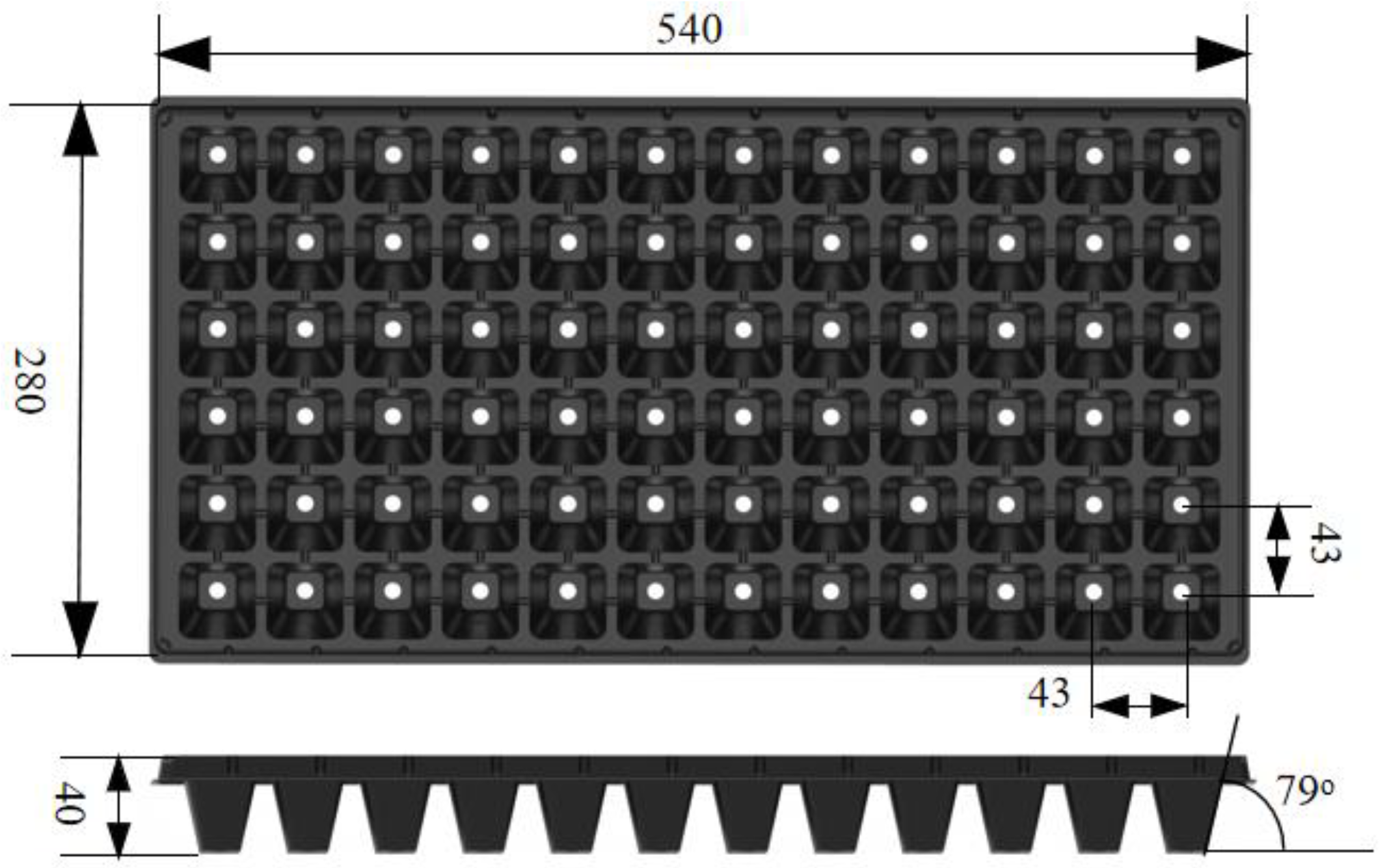
Figure 1. Seedling tray specifications (mm).
Agriculture 12 01989 g001
Figure 2. (a) The seedling-picking mechanism. (b) The seedling-picking executive component. 1. Seedling tray conveying device; 2. longitudinal driving cylinder; 3. seedling-picking installation plate; 4. seedling-picking executive assembly; 5. 72-hole seedling tray; 6. longitudinal linear slide rail; 7. seedling guide tube; 8. seedling-picking frame; 9. seedling claw; 10. horizontal linear cylinder; 11. longitudinal cylinder mounting plate; 12. clamping cylinder; 13. horizontal linear bearing; 14. lifting cylinder.
Agriculture 12 01989 g002
Figure 3. Schematic diagram of the process of picking seedlings: (a) Seedling-picking stage; (b) conveying stage from seedling-picking position to seedling-throwing position; (c) the stage of seedling-throwing pot; (d) reduction process.
Agriculture 12 01989 g003
Figure 4. Diagram of seedling-picking claw clamping seedling pot:(a) structure diagram of seedling-picking claw; (b) stress analysis diagram of seedling-picking claw and pot body.
Agriculture 12 01989 g004
Figure 5. Pneumatic system diagram of seedling-picking mechanism: A is the lifting cylinder; B1 and B2 are the clamping cylinders; C is the horizontal cylinder; D is the longitudinal cylinder; J1–J10 are the throttle valves; S1–S5 are the solenoid valves; R is the safety valve; P is the air source; T is the air source regulating device.
Agriculture 12 01989 g005
Figure 6. High-speed cylinder simulation model.
Agriculture 12 01989 g006
Figure 7. (a) Response surface of the effect of n 1 and n 2 on the time taken for cylinder stabilization when p 1   = 0.4 MPa; (b) response surface of the effect of p 1 and n 2 on the time taken for cylinder stabilization when n 1   = 0.7; (c) response surface of the effect of p 1 and n 1 on the time taken for cylinder stabilization when n 2   = 0.7.
Agriculture 12 01989 g007
Figure 8. (a) Response surface of the effect of n 1 and n 2 on the maximum acceleration of the cylinder when p 1   = 0.4 MPa; (b) response surface of the effect of p 1 and n 2 on the maximum acceleration of the cylinder when n 1   = 0.7; (c) response surface of the effect of p 1 and n 1 on the maximum acceleration of the cylinder when n 2   = 0.7.
Agriculture 12 01989 g008
Figure 9. Comparison of response surface optimization results: (a) comparison of results before and after optimization of cylinder speed; (b) comparison of results before and after optimization of cylinder acceleration.
Agriculture 12 01989 g009
Figure 10. Test equipment and conditions: (a) 72-hole plug seedlings; (b) growth of cucumber seedlings; (c) pick-up mechanism; (d) bench test of picking seedlings.
Agriculture 12 01989 g010
Table 1. Calculation results of cylinder inner diameter.
Cylinder NameWorking Air Pressure/MPaStroke/mmLoad/kgCylinder Inner
Diameter/mm
Horizontal cylinder0.42006.5≥12.9
Longitudinal cylinder0.440028.66≥28.6
Table 2. Calculations result of air consumption.
Cylinder NameTypeFrequencyDiameter/cmStroke/cmNumberAir Consumption/(L·min−1)
Clamping cylinderMD 16 × 40241.64611.58
Lifting cylinderTCL 25 × 50-S242.55211.78
Horizontal cylinderMA 16 × 200-S241.620219.30
Longitudinal cylinderSC 32 × 400-S243.240177.20
Sum 119.86
Table 3. Calculation results of kinetic energy (Note: Data are obtained by kinetic energy formula).
Cylinder NameOperating Time/sStroke/mmVelocity/(m·s−1)Load/kgKinetic Energy/J
Clamping cylinder0.540800.20.00
Lifting cylinder0.5501004.20.02
Horizontal cylinder12002006.50.13
Longitudinal cylinder140040028.662.29
Table 4. Main simulation technical parameters of high-speed cylinder.
ParameterNameValueUnits
KAir insulation parameters1.4——
PsAir pressure0.3–0.5MPa
MLoad (Seedling execution component)28.66kg
FsLoad static friction10N
FfLoad sliding friction12N
DCylinder piston diameter32mm
dDiameter of cylinder piston rod12mm
LnCylinder buffer stroke21mm
kCylinder cushion material stiffness2855N/mm
cCylinder cushion material damping12N/(mm/s)
Table 5. Aerodynamic parameter response surface test results.
Serial NumberAir Source Pressure
(p1/MPa)
Flow Coefficient of Speed-Control Valve (n1)Flow Coefficient of Safety Valve (n2) Maximum Speed of Cylinder
(vmax/m·s−1)
Time to Stabilize
(tst/s)
Maximum
Acceleration
(amax/m·s−2)
10.400.700.701.538140.92−196.265
20.500.700.501.602690.87−28.6913
30.300.700.501.424481.00−391.005
40.400.700.701.538140.92−196.265
50.300.700.901.424471.00−391.09
60.400.900.501.519980.92−65.5597
70.400.900.901.520020.92−65.6388
80.500.700.901.602720.87−28.692
90.400.500.901.520290.9328.8986
100.400.700.701.538140.92−196.265
110.300.900.701.429711.00−240.411
120.500.500.701.622990.87−426.561
130.400.700.701.538140.92−196.265
140.300.500.701.411661.00−24.2564
150.400.500.501.520290.9328.9134
160.400.700.701.538140.92−196.265
170.500.900.701.608860.8637.4641
Table 6. Target parameter setting value.
NameOptimization GoalUpper LimitLower Limit
Cylinder stabilization time (s)minimum1.0000.860
Maximum acceleration of cylinder operation (m·s−2)minimum37.464−426.561
Cylinder running maximum speed (m·s−1)maximum1.6231.412
Table 7. Parameter optimization settings.
NameGoalLower LimitUpper LimitLower WeightUpper Weight Importance
Air Source Pressure ( p 1 / MP a )within rang0.3000.500113
Flow Coefficient ( n 1 )within rang0.5000.900113
Flow Coefficient ( n 2 )within rang0.5000.900113
Table 8. Parameter optimization results.
Serial NumberAir Source Pressure
(p1/MPa)
Flow Coefficient (n1)Flow Coefficient (n2) Maximum Speed
(vmax/m·s−1)
Time to Stabilize
(tst/s)
Maximum Acceleration
(amax/m·s−2)
Desirability
10.500.870.701.603820.86755937.45510.946
20.500.870.711.603820.86755937.46120.946
30.500.870.711.603820.8675637.45890.946
Table 9. Test results of seedling collection.
Seedling
Frequency
The Total Number of Pot Seedlings (N)The Number of Missing Seedlings (q)The Number of Damaged Seedlings (n)The Number of Damaged Pots (m)Damage Rate of Pot Body (%)Average Damage Rate of Pot Body (%)The Success Rate of Taking Seedlings (%)Average Seedling Success Rate (%)
120 plants·min−1 (Before optimization)2162241.91.796.396.4
2161231.497.2
2163241.995.8
120 plants·min−1 (optimized)2162110.50.798.197.9
2162120.997.6
2161120.998.1
144 plants·min−1 (Before optimization)21634104.64.392.192.4
2163383.793.5
21644104.691.6
144 plants·min−1 (optimized)2163331.41.695.895.3
2164331.495.3
2163441.994.9
Publisher’s Note: MDPI stays neutral with regard to jurisdictional claims in published maps and institutional affiliations.