Abstract
Double-arm picking robots are widely used in agricultural production for their high collaborative efficiency. While picking, area planning and collision detection between the mechanical arms is a crucial challenge for the double-arm robot, which needs to establish a collision-free path for fruit picking. In this study, we developed a double-arm cooperation method for robotic picking of kiwifruit. Firstly, the problem of dividing the picking area was simplified into a multiple traveling salesmen problem (MTSP) to be solved. The picking sequence of each robotic arm was formulated by the principle of similar picking numbers, and combined with the brainstorming optimization algorithm (BSO). Secondly, a double-arm parameter model was built to solve the forward and backward movements of the robotic arms and to figure out the joint position. The spatial mathematical relationship of the bounding boxes between the robotic arms was used to detect the collision between the two robotic arms, in order to achieve the avoidance between the robotic joints. Then, simulation software was applied to the simulation and analyzed the availability of picking area planning and collision detection. The simulation results showed that the optimized picking sequence planning using BSO was more efficient; the smooth joint trajectory during the movement of the robotic arms met the limits on the range of movement and on the angular velocity of the robotic arm joints. Finally, based on the simulation result, a double-arm collaboration platform was tested. The double-arm collaboration platform harvesting trials showed that the average picking success rate was 86.67%, and collision detection time was 3.95 ± 0.83 s per fruit. These results indicated that the proposed method could plan the operation tasks of the double-arm picking robot system, and effectively implement the collision-free picking operation.
1. Introduction
Kiwifruits are favored among consumers and widely planted for being rich in vitamin C [1]. China is the world’s largest agricultural country in terms of kiwifruit planting area and production, with its annual yield exceeding 3 million tons [2]. The kiwifruit industry in China is still labor-intensive compared to developed countries, which especially manifests in the time-consuming and laborious harvesting process [3]. Shaanxi Province, with 5.3 × 10⁴ hectares of kiwifruit plantation, has the highest yield of kiwifruits in China and a productive capacity of 9.48 × 10⁵ tons of kiwifruit [4]. However, kiwifruits have previously relied on high labor cost manual picking during the harvest seasons.
The seasonal labor shortage and the annual increase in labor costs severely limit the development of the kiwifruit industry. Therefore, many scholars have proposed the use of agricultural robots to make up for the shortcomings of manual harvesting [5]. In recent years, remarkable achievements have been made in end-effector design [6], picking mechanism [7,8], fruit recognition [9,10], and path planning [11,12] of agricultural harvesting robots. However, the application of robotics in agriculture is more complex and challenging than the implementation of industrial automation. The highly unstructured nature of the agricultural environment, differing from stable environment of industry, and the easy damageability of fruits have restricted the function of agricultural robots [13]. Agricultural robots are more time-consuming in recognizing objects and harvesting fruits, and cannot meet the realistic demand of picking operations. Therefore, the picking efficiency of the robots should be improved in terms of harvesting time per fruit and recognition accuracy in the complex agricultural environment.
As is known, a single robotic arm can hardly perform complex picking tasks or simple tasks in a complex environment in an efficient manner [14]. Therefore, researchers have attempted to improve the harvesting efficiency using multi-arm parallel harvesting. Among them, Ling et al. [15] developed two 4-degree-of-freedom tandem robotic arm structures to harvest tomatoes, and achieved an 87.5% picking success rate combined with 3D reconstruction technology; Tao Li et al. [16] used four right-angle coordinated robotic arms for a collaborative picking operation in a dwarf dense apple orchard; FFRobotics Company [17] used 12 robotic arms for rapid picking of two rows of apples. Multi-arm harvesting of kiwifruits is still a challenge. The key problem can be described as collision between robotic arms during picking.
Compared to single-arm operating, multi-arm operating requires not only consideration of task planning for robotic arm picking [18], but also additional consideration of collision detection between robotic arms [19]. Williams [20] used two-dimensional Euclidean distance between fruits as a condition for clustering partitioning of kiwifruits. Collision detection between robotic arms is frequently performed by the geometric model method and artificial potential field. Xiong et al. [21] planned a cooperative picking operation task among robotic arms in a right-angle coordinate system by setting the safety distance of robotic arms; Lei et al. [22] constructed a robotic arm joint model using spheres and carried out the collision detection of the robotic arm by establishing the geometrical relationship between the spheres; Wang et al. [23] proposed an artificial potential field method based on an improved attractive potential function in order to enhance the efficiency of robotic arm collision detection. There is a randomness in the planning of picking areas based on fruit distribution, which increases the risk of mechanical collisions between robotic arms. Therefore, the purpose of this study was to investigate efficient and accurate methods of collaborative operations with double robotic arms.
In this study, we aimed to addressed the problem by focusing on dual-arm cooperation in relation to picking area planning and collision detection. The remainder of this article is structured as follows: Section 2.1, Section 2.2 and Section 2.3 describe the system structure of double-arm harvesting robot, including the hardware system, software system, and cooperative approach. Section 2.4 and Section 2.5 present the method of picking area planning and collision detection between the mechanical arms. Section 3 describes and presents the experiments and the simulation results. Finally, the conclusion is presented in Section 4.
2. Materials and Methods
2.1. Kiwifruit Trellis Cultivation Structure
The cultivation of the kiwifruit trees was mainly performed by trellis cultivation. The method of building trellises was used to fix and support the branches and vines of kiwifruits, accelerate the growth and development of the branches and vines, and provide a good growth environment for the fruits. The trellis cultivation mode is shown in Figure 1a. The bottom of each trellis is large and flat (width 4 m × spacing 2 m × height 1.8 m); there is enough and appropriate space for kiwifruit picking robots to perform robotized mobile picking operations under the trellis. As shown in Figure 1b, each kiwifruit tree has multiple fruit clusters growing together, each of which consists of 2–7 fruits, and generally only 2–3 fruits at the same height. Fruit distribution differs by height. When viewed from the bottom up, a few kiwifruits may be overshadowed by leaves and branches.
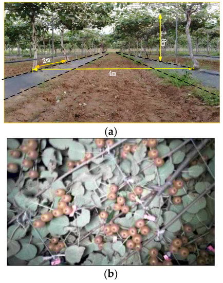
Figure 1.
Kiwifruit shelf cultivation model. (a) Trellis cultivation mode. (b) Clustered kiwifruit.
2.2. System Overview
The research object of this paper is a double-arm picking robot, which is mainly used in kiwifruit orchards. Parameters needed for the design process include the working height of fruit picking (1.45~1.85 m), the weight of the load end effector (about 2.5 kg), and the fruit separation force (3~10 N), in addition to the requirements of high position control accuracy and avoidance of damage to adjacent fruits. As shown in Figure 2a, the test platform consisted of two UR5 (Universal Robots) robotic arms and a mobile platform. Each of the robotic arms has a working radius of 0.85 m and a payload of 5 kg, which is suitable for driving a 2.5 kg end effector to perform the kiwifruit picking task.
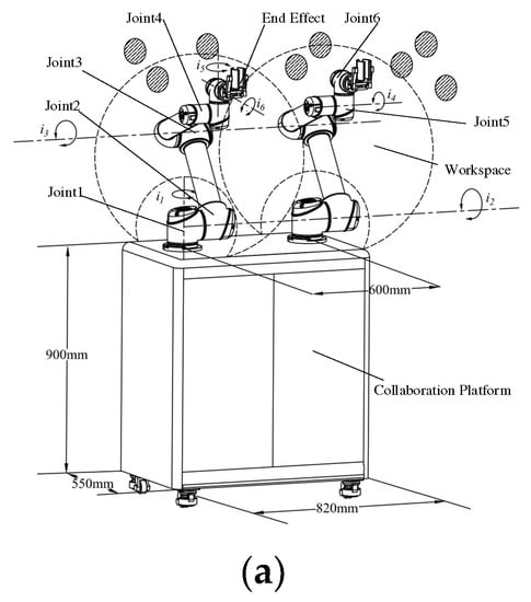
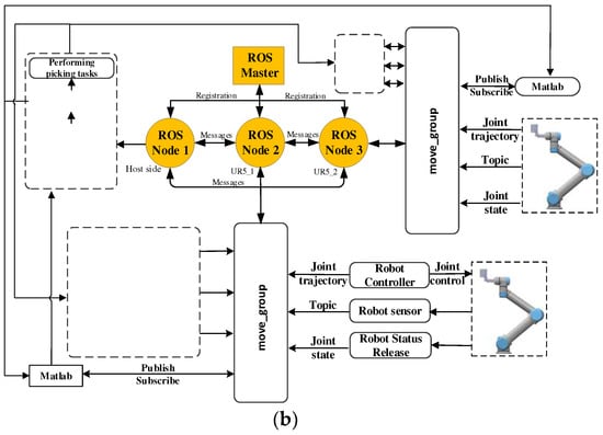
Figure 2.
Overview of the double-arm harvesting robot. (a) Double-arm harvesting platform. (b) The robot operating system based on software architecture of the double-arm robot.
In order to implement the double-arm harvesting operation, the distributed communication network is adopted in the software. The distributed communication network, which was built in the robot operating system by publishing and subscribing to topics, implemented concurrent computing and issues commands between the host side and the slave side. As shown in Figure 2b, the software framework consists of four steps: fruit detection, motion planning, collision detection, and motion control. In the first step, the slave side captures images by driving the camera, pinpoints the fruits in the images using the trained YOLO mode, and publishes the 3D coordinates of fruits as a topic in a distributed network. In the second step, the host side subscribes to the fruit coordinate topic and performs picking sequence planning and robotic arm joint angle motion planning. In the third step, the host side also performs collision detection for each joint simultaneously in the robotic arm motion planning, and publishes motion planning information in the form of topics. In the fourth step, double robotic arm picking operations are controlled on the machine side by subscribing to host-side picking sequences and motion planning information topics. In addition, the planning of the next fruit picking and collision detection are implemented at the host end, while picking operations of the robotic arms are controlled at the slave end. After completing this picking task at the slave side, the slave side subscribes to the movement planning information on the host side before performing the next fruit picking task.
2.3. Collaborative Operation Method of Kiwifruit Picking Robots
The collaborative operation approach includes picking area planning and collision detection, with the aim of reducing the chance of collision between the two arms and, thereby, to avoid mechanical collision of the double-arm picking robot during the picking operation. The flowchart of collaborative operation of the double-arm picking robot is shown in Figure 3, which can be summarized in three general steps:
- After determining the picking position, the picking area for each robotic arm is divided into a pickable subarea and a collision-prone subarea based on the robot arm’s installation position and work space. Based on this division, the picking order in the pickable subarea is set, and the solution is optimized by BSO in combination with the growth characteristics of the kiwifruits distributed in clusters.
- Collision is detected between robotic arms in the collision-prone subarea, while the joint position and the kinematic solution of the robotic arms are figured out. After determining the collision situation between robotic arms, a delayed picking strategy is adopted wherever a collision is detected.
- An integrated “grab-pick-unload-reset” continuous kiwifruit picking cycle is developed, and the next task is planned when both arms have finished the current picking task. In addition, the kiwifruit was harvested without damage when the pressure between the end-effector and the fruit was less than 18.8 kpa [24].

Figure 3.
Flow diagram of the double-arm.
2.4. Kiwifruit Picking Area Planning
As shown in Figure 4, two single-arm robots harvesting fruits simultaneously are prone to leakage of kiwifruit without collision. Compared to two single-arm robots, the overlap between the respective working areas of the two-armed robots allows for more kiwifruit picking in the canopy of the greenhouse as well as a reduction in fruit leakage rates (Figure 5).
Figure 4.
Schematic diagram of multi-robots working: 1—left robotic arm; 2—left robotic arm workspace; 3—mobile platform; 4—right robotic arm; 5—right robotic arm workspace; 6—shelf.
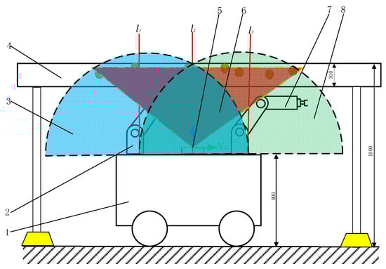
Figure 5.
Schematic diagram of picking area division: 1—double-arm collaboration platform; 2—left robotic arm; 3—left robotic arm workspace; 4—shelf; 5—depth camera; 6—camera imaging space; 7—right robotic arm; 8—right robotic arm workspace.
The picking scheme was formulated based on the camera imaging space and the positional relationship between the robotic arms and the working space (Figure 5). The picking area in the image was divided into the pickable and collision-prone subareas by applying the concept of orthogonal coordinate planes. On this basis, the double-arm picking sequence planning problem was simplified into the MTSP. The BSO, adopting the idea of clustering, was used to optimize the picking order results based on the natural characteristics of kiwifruit growth in clusters.
The MTSP, as a combinatorial optimization problem, is generally described as multiple travelers planning different travel routes from the same city or different cities for the optimal result of the shortest time. The planning process ensures that each city is traversed by one traveler. The double robotic arm picking planning process is analogous to the MTSP; the fruits in the image captured by the camera act like the cities in the MTSP, the two robotic arms behave like the multiple travelers, and the movement time of the robotic arms and the picking time of a single fruit are comparable to each traveler’s arrival time to a city and the time that they remain in the city.
The BSO for the solution to MTSP was proposed to solve the problem of kiwifruit picking planning. After determining the number of fruit samples and algorithm parameters, the picking order was iterated according to the clustering, variation, crossover, and generation of new individuals as well as selection in the BSO [25]. Finally, the optimal picking order meeting the conditions was solved.
2.4.1. Clustering
After parameter initialization, the picking area was divided into the pickable subarea and the collision-prone subarea. The spatial distance between fruits was selected as the objective function of the clustering object, and the fruits were clustered using the K-means algorithm. The fruits were ranked according to the magnitude of the three-dimensional Euclidean distance between them, with the highest-ranked noted as the center of the class in which it was located, in combination with the fitness function.
2.4.2. Variation and Crossover
Variation: the central individuals in clusters were determined with a certain probability to replace the original ones in a random way.
Crossover: as shown in Figure 6, in order to obtain the optimal picking sequence, first, the cross update sequence is recorded as child_1, two different fruit picking sequences and a random fruit as the start node are recorded as parent_1, parent_2, and start, respectively, and the updated fruit node is recorded as num. The numbered fruit as the start node is located somewhere in each fruit picking sequence, and the fruit next to the start on the right is extracted as the candidate node. Then, the spatial distance between the candidate node and the start node in one picking sequence is compared with that in the other picking sequence, and the candidate node at a smaller distance from the current start node in the same sequence is updated as the next start node of picking in child_1. This step is repeated over and over again until all the fruits have been traversed as the start node.
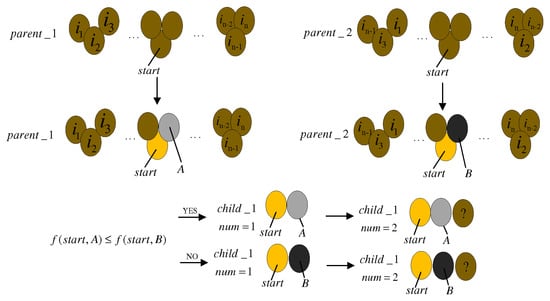
Figure 6.
Schematic diagram of brainstorming crossover process.
2.4.3. Generation of New Individuals
The clustered individuals are sorted according to the value of the objective function, and new individuals are generated by selecting each clustering center, and then compared with the random probability Prand and the preset clustering probabilities P1 and P2, as follows.
Step 1: determine the random probability Prand.
Step 2: if Prand < min{P1, P1-center}, where P1-center is the clustering center probability, then no new individual is generated; otherwise, the clustering center is randomly generated and a new picking sequence is figured out, and the crossover operation is performed on the previous picking sequence.
Step 3: if Prand < min{P2, P2-center}, where P2-center is the clustering center probability, then no new individual is generated; otherwise, two picking sequences are generated and crossed with the original picking sequences, respectively.
2.4.4. Selection
After the new sequence is generated, the node with the optimal value of the fitness function is selected by comparison with the candidate nodes. The generation of new individuals is repeated until the maximum number of iterations is reached and the algorithm ends.
2.5. Double-Arm Picking Robot Collision Detection
2.5.1. Simplified Model of Robotic Arms
The UR5 robotic arm, as an irregular object, is composed of multiple complex parts. Failure to streamline the robotic arm model could lead to low efficiency of collision detection. As shown in Figure 7, the UR5 robotic arm was modeled by the Denavit–Hartenberg (D–H) parametric method to simplify the collision detection calculation. The kinematic parameters of the connecting rods were determined according to the connection between the joints, as shown in Table 1.
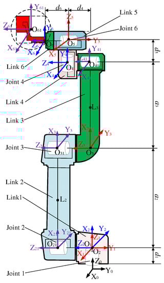
Figure 7.
UR5 robotic arm modeled by the D–H parameter method.

Table 1.
D–H parameters.
By the principle of positive kinematics of the robotic arm and D–H parametric, the transformation matrix is expressed as:
where is the transformation matrix of the ()th coordinate system relative to the th coordinate system; and are the joint angle and the linkage offset of the ()th joint, respectively; and and are the joint angle and the linkage length of the th joint, respectively. The direction of is determined by the right hand rule [26].
The transformation matrix of each joint, with respect to the base coordinates, is expressed as:
where is the transformation matrix of the base coordinate system relative to the th coordinate system; is the rotation matrix; and is the translation matrix.
Coordinates of each joint center point are expressed as:
As shown in Figure 7, the auxiliary coordinate systems O21X21Y21Z21, O31X31Y31Z31, O41X41Y41Z41, and O61X61Y61Z61 are constructed. The coordinate systems O21X21Y21Z21, O31X31Y31Z31, and O41X41Y41Z41 are located at the center of the joint and on the same joint axis (Z-axis) as the coordinate systems O2X2Y2Z2, O3X3Y3Z3, and O4X4Y4Z4, respectively. The robotic arm joints are rotational joints, whose rotation angle can be used to determine the spatial relationship between the other two axes of the auxiliary coordinate system. Using the sphere to envelop the end-effector, the auxiliary coordinate system of the end-effector is O61X61Y61Z61.
The transformation relationships between the auxiliary coordinate system and the coordinate systems O2X2Y2Z2, O3X3Y3Z3, O4 X4Y4Z4 are given by:
The transformation matrix of the auxiliary coordinate system relative to the base coordinate system is expressed as
The coordinates of the center of the connecting rod are expressed as
where is the coordinate of the center of the connecting rod between the th joint and the ()th joint.
A capsule body was used to envelop each joint and linkage of the robotic arms. The end-effector is composed of a base, pneumatic finger, and gripping device for harvesting kiwifruit. As shown in Figure 8a, the gripping device grasps and releases the fruit with the reciprocating motion of a pneumatic finger. Considering the shape and size of the end-effector, replacing the end-effector with the capsule body could lead to errors. Finally, this study used six capsule bodies and one sphere to simplify the UR5 robotic arm model, as shown in Figure 8. The spatial position of the bounding boxes was determined based on the calculated spatial coordinates of each joint and the center coordinates of each linkage.
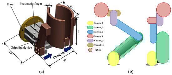
Figure 8.
Simplified model of robotic arm. (a) Diagram of end-effector structure (b) Diagram of robotic arm structure.
Each of the capsule bodies can be considered to have geometry consisting of two hemispheres and a cylinder. The radius of each hemisphere was determined by the joint dimensions, whereas the height of the cylinder was determined by the length of the robotic arm linkage. The parameters of the bounding boxes are shown in Table 2.
Table 2.
Bounding volume parameters.
2.5.2. Collision Detection Methods
The collision detection between robotic arms was simplified into collision detection between each capsule body and the sphere, and between capsule bodies. The minimum distance between the two enclosed bodies needs to satisfy the corresponding constraint in order to be considered if no collision occurs. The minimum distance between the sphere and each capsule body can be simplified as the point-to-line distance from the center of the sphere to the central axis of each capsule body. The minimum distance between capsule bodies needs to allow for the position of the nearest point between their central axes, according to which the decision of whether a collision occurs is made.
From Figure 9a, the collision condition between spheres is expressed as
where is the distance between the centers of spheres; and and are the radii of the spheres centered at Oa and Ob, respectively.
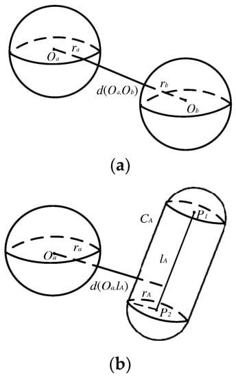
Figure 9.
Enclosure space distance. (a) Diagram of the distance between spheres. (b) Diagram of the distance between spheres and capsules.
As shown in Figure 9b, the collision condition between the sphere and the capsule is expressed as:
where is the distance from the center of the sphere to the central axis of the capsule body centered at Oa; and is the radius of the capsule body.
As shown in Figure 10, the capsule body is represented by the sets and , respectively; the central axis segments are represented by the sets and , respectively; and the radii are represented by and , respectively. The points and inside the capsule body are subject to the following constraints.
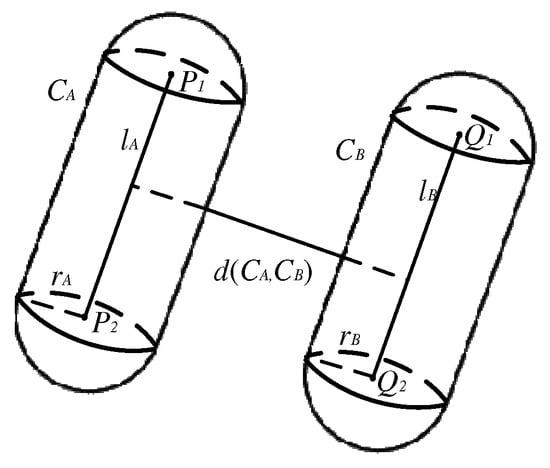
Figure 10.
Capsule body space distance.
If the minimum distance between the segments of the central axis of the capsule bodies meets the condition that it is greater than 1.3 times the sum of the radii of the capsule bodies, then it can be considered that no collision occurs.
where is the minimum distance between the axial segments; and and are the radii of the capsule bodies.
Spatial central axis segments and can be expressed as:
where and are the endpoints of the line segment ; and are the endpoints of the line segment ; and u and v are the direction vectors of the line segment.
The minimum distance between the line segments lA and lB can be expressed as:
From the minimization conditions and , λ1 and λ2 can be determined as:
Considering the variable positions of the spatial line segments, the positions of the nearest points between the two line segments are classified into four types, as shown in Figure 11. If the two spatial line segments intersect (Figure 11a), the nearest point is located at the intersection of the two line segments; if the two spatial segments are parallel or located on two parallel planes (Figure 11b), the nearest point is inside the two segments; otherwise, if the two line segments are distinct (Figure 11c,d), there are two cases: (i) the endpoint of one line segment and the interior of the other line segment are at the nearest point, and (ii) the endpoints of the two line segments are at the nearest point.
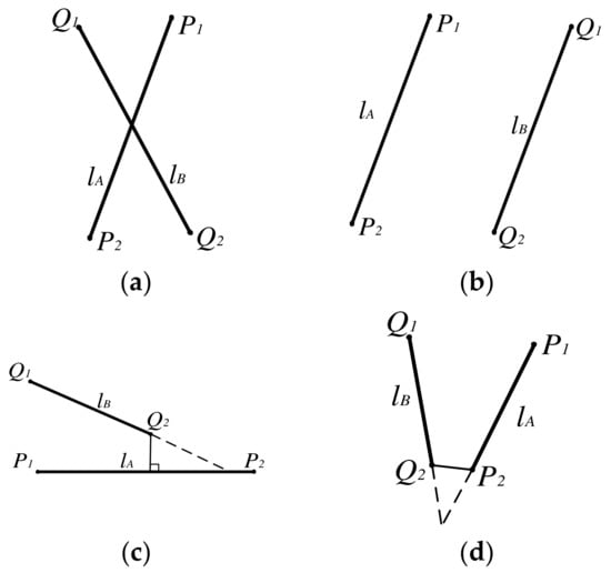
Figure 11.
Schematic diagram of the position of the closest point between the line segments. (a) intersecting line segments (b) Parallel line segments (c) Contour segment (d) Contour segment.
If , the minimum distance between the two central axes is , otherwise, the minimum distance can be expressed as:
where and are the minimum distances from points and to line segment , respectively; and are the minimum distances from points and to line segment , respectively.
3. Result and Discussion
3.1. Evaluation of the Picking Area Planning Algorithm
The experimental site was located in the Kiwifruit Experiment Station in Meixian County, Northwest Agriculture and Forestry University (34°07′39″ N, 107°59′50″ E, elevation 648 m), where the breed of kiwifruits was Hayward. Combined with our previous research base [24,27], the double robotic arm picking platform used the trained Yolo v4 recognition model to recognize the collected images. The recognition results are shown in Figure 12. The 3D coordinates of fruits were derived based on the depth information, camera pixel coordinate system, and world coordinate system conversion relationship. We used BOA to optimize the picking sequence, while the genetic algorithm (GA) simulated the annealing algorithm (SA) and the particle swarm algorithm (PSO) for the control group. The algorithm parameters are shown in Table 3 and the experimental results are shown in Table 4.
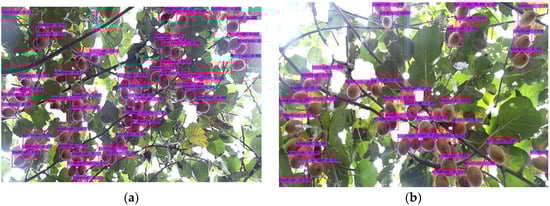
Figure 12.
Double-arm picking robot fruit planning test. (a) Scenario 1 recognition results. (b) Scenario 2 recognition results.
Table 3.
Algorithm parameters.
Table 4.
Kiwifruit planning test results.
The experimental results are shown in Table 4. The results of the fruit picking planning experiment in Scenario 1 showed that four kiwifruits failed to be recognized (Figure 12a), and that the fruit recognition rate was 92.31%. Compared with other algorithms’ optimized picking sequences, the BSO used in this paper is optimal in computation time. As shown in Figure 13, BSO converges to the optimal value when the number of iterations reaches 29 and 22, while the SA, GA, and PSO algorithms do not converge until the number of iterations reaches 400.
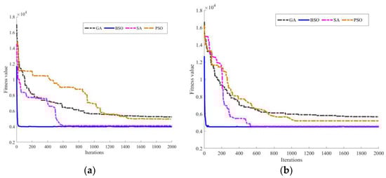
Figure 13.
Experiment results of kiwifruit picking task planning. (a) Scenario 1 convergence curve. (b) Scenario 2 convergence curve.
The method used hereof remains prone to fruit misidentification due to overhigh light intensity and shading by branches and leaves. The BSO used in this paper outperforms the GA-optimized picking sequence in terms of convergence speed and convergence accuracy. As shown in Figure 13, as the number of fruits increases to enlarge the search space, the convergence speed of GA decreases dramatically, and the algorithm tends to become trapped in a local optimum. Since kiwifruits grow in clusters, the BSO can shrink the search space and the number of iterations by using clustering, thus improving the speed and efficiency of searching for the optimal solution.
The simulation results verify the accuracy of the proposed picking area planning algorithm. Fruit misidentification caused by natural factors still occurs. The influence of direct sunlight cannot be avoided in the fruit detection. Single sensors are more limited in terms of recognition, and a multi-sensor fusion approach to recognition will reduce this impact. In addition, the outliers have strong influence on the K-means clustering method, causing the curve of BSO optimization to oscillate at the optimal value [28,29].
3.2. Simulation on Collision Detection of the Double-Arm Picking Robot
The collision detection test between the double mechanical arm is destructive, and the direct physical prototype experiment easily causes physical collision. Simulation is often used in the robotics field to verify whether the proposed planning method is reasonable or not. In order to test the effectiveness of the collision detection algorithm and to decide whether the joint parameters meet the criteria during the motion, we performed a simulation of collision detection for the double-arm picking robot.
The double-robotic arm picking robot model consists of a base and two 6-degree-of-freedom UR5 robotic arms (Figure 14). The base is a rectangular solid of dimensions 1 m × 1 m × 0.2 m. The distance between each robotic arm and the center of the base is 0.6 m. The robot arm simulation model was integrated with three parts of information: the UR5 parameters, the joint connection relationship, and URDF (Unified Robot Description Format). The rotation, translation, solver configuration, and mechanism configuration of the joints and the model were established using the simscape module in MATLAB. Equations (1)–(5) are applied in the simulation to calculate the center coordinates of the connecting rod, and Equations (6), (7), and (10) are employed for collision detection. Based on this, the robot toolbox was used for motion planning of the robotic arms combined with the picking sequence and collision strategy.
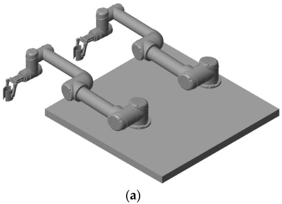
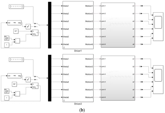
Figure 14.
Double-arm simulation model. (a) Simscape model. (b) Simulink model.
In order to test the effectiveness of the collision detection algorithm, fruits in the pickable and collision-prone subareas were picked separately in the double-arm collision detection test. The fruit coordinates in the pickable subarea were (−0.28 m, 0.08 m, 0.7 m) and (−0.165 m, 0.28 m, 0.716 m). The kiwifruits were replaced with brown orbs during the simulation. The initial and target states of the robotic arms are shown in Table 5. Simulation was performed using the robot toolbox and Simulink module. The robotic arm picking area simulation process is shown in Figure 15. This picking plan uses the spatial relationship between joints 1–3 of each robotic arm and the end-effector in each movement interval as a collision detection condition. At the time interval of 0.2 s, a total of 18 collisions were detected during the movement. Combined with the obstacle avoidance strategy, only joints 1–3 of each robotic arm and the end-effector were detected in the fruits in the pickable subarea. The tendency of collision between robotic arms was not detected in the simulation. The robot arms operated by the “positioning-picking-unloading-fruit-reset” picking procedure, and no collision was detected during the motion simulation (Figure 15). The angle and angular velocity change curves of the joints of both arms are shown in Figure 16, which demonstrates that the joints changed smoothly during the entire picking planning process, meeting the limits of the joint motion range and angular velocity of the UR5 robotic arms.
Table 5.
Pickable area robotic arm joint information.
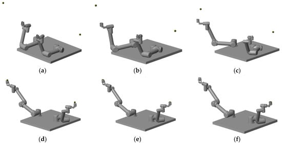
Figure 15.
The motion simulation process of the pickable area with the double-arm. (a) Initial position. (b) Collision detection. (c) Dual robotic arm planning path. (d) Locating the fruit. (e) Grabbing the fruit. (f) Separating the fruit.
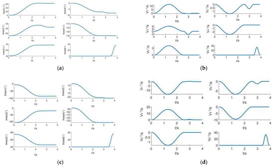
Figure 16.
Motion simulation results of the pickable area with double-arm. (a) Left arm joint angle change curve. (b) Left arm joint angular velocity variation curve. (c) Right arm joint angle variation curve. (d) Right arm joint angular velocity variation curve.
The fruit coordinates in the collision-prone subarea were (−0.145 m, 0.860 m, 0.729 m) and (−0.12 m, −0830 m, 0.672 m), and the initial and target states of the robotic arms are shown in Table 6. In order to visually check the simulation test effect, without considering collision detection, an obvious collision occurred between the robotic arms in the picking state, as shown in Figure 17.
Table 6.
Joint information of the robot arm in the collision area.
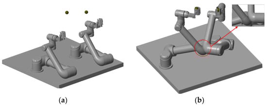
Figure 17.
Two-arm picking plan in the collision area. (a) No collision detection. (b) Collision location.
In order to accomplish the collision-free picking task, we added the collision detection algorithm to the simulation experiment. This picking planning took the spatial relationship of each joint at each motion interval as the collision detection condition. At the time interval of 0.2 s, a total of 45 collisions were detected during the movement. The movement process between the mechanical arms is shown in Figure 18. A collision between joint 3 of the left arm and joint 3 of the right arm was detected at 1.6 s of motion planning. In order to avoid collision, the right arm was not enabled for the picking of this target before the left arm completed the picking task. After the left arm reached the initial position, collision detection only identified the spatial relationship between joints 1–3 of each robotic arm and the end-effector. The angle and angular velocity change curves of each joint of the two arms are shown in Figure 19. The results showed that the joints changed gently during the movement, satisfying the movement limits of the robotic arms. The collision position could be effectively detected during the collaborative picking process of the two arms. As shown in Figure 20, the collision detection method avoided collision points between robotic arms and achieved cooperative operation of both robotic arms in the collision-prone subarea.
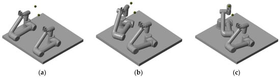
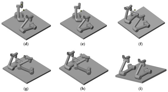
Figure 18.
Simulation process of two-arm movement in the collision area. (a) Initial position. (b) Collision detection. (c) Left robot arm positioning fruit. (d) The left robot arm grasps the fruit. (e) The left robot arm separates the fruit. (f) The left robot arm reaches the initial position. (g) The right robot arm grasps the fruit. (h) The right robot arm separates the fruit. (i) The right robot arm reaches the initial position.
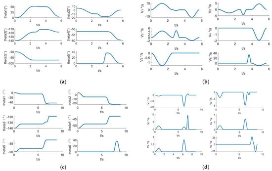
Figure 19.
Motion simulation results of the double-arm in the collision area. (a) Left arm joint angle change curve. (b) Left arm joint angular velocity variation curve. (c) Right arm joint angle change curve. (d) Right arm joint angular velocity variation curve.
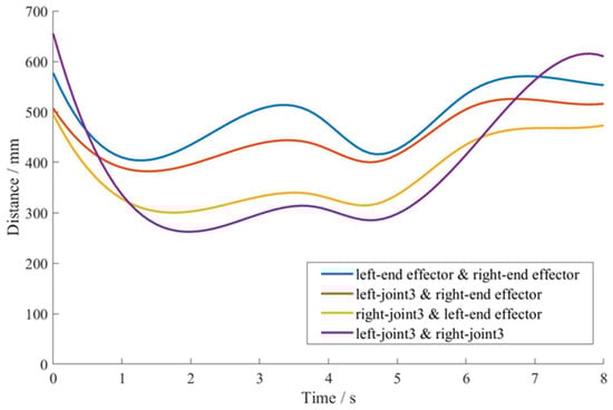
Figure 20.
Collision detection distance.
3.3. Experimental Verification
3.3.1. Picking Test Platform
The system makeup of this test platform is shown in Figure 21. It consists of two Universal Robots (UR5) with 6 degrees of freedom. The joint motion range of each robotic arm is 360°, and the maximum running angular speed of the joint is 180°/s. The Universal Robots dual-arm collaboration platform serves as the test platform, with dimensions (L, W, H) of 820 * 550 * 900, which can supply power to and dissipate heat from the robotic arms at the same time. Depth camera (RealSense D435i, Intel, Santa Clara, CA, USA) was used to capture images, with a depth distance ranging from 0.1 m to 10 m and a depth error of less than 2%. A distributed communication network was formed by a laptop computer and two embedded devices, where the embedded devices were configured with jetson Tx2 and Nano (Nvidia, Nvidia Corporation, Santa Clara, CA, USA). The embedded device system was configured with Ubuntu16.04, and the ROS (Robot Operating System) Kinect version was installed to control the manipulator.
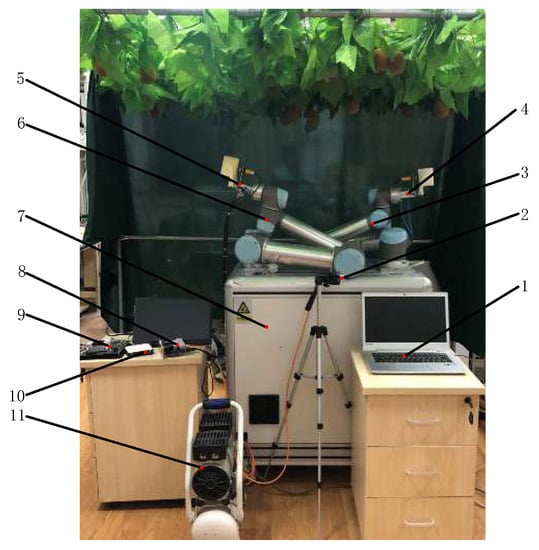
Figure 21.
Double-arm harvesting robot test platform: 1—host end; 2—depth camera; 3—right robotic arm; 4—end-effector one; 5—end-effector two; 6—left robotic arm; 7—dual-arm collaboration platform; 8—jetson nano; 9—jetson Tx2; 10—switch; 11—air compressor.
3.3.2. Experiment on the Double-Arm Picking Robot
In order to verify the feasibility of the collaborative operation method in this paper, a validation experiment of a double-arm picking physical platform was conducted in combination. This experiment was based on Robot Operating System (ROS) and MATLAB for picking planning. The YOLOv4 training model was used to recognize the panoramic images of fruits captured by the depth camera. Based on the calibration relationship among the world coordinate system, camera coordinate system, image plane coordinate system, and robot arm coordinate system, the spatial coordinates of the grasped target were calculated relative to the robotic arm base. The spatial information of the fruits was published in the form of topics. On this basis, the picking order was formulated in combination with the region division method proposed in this paper. The trajectory planning of the robotic arms with a time of 4 s was carried out. At a time interval of 0.2 s, the robot toolbox was used to detect the collision of the spatial relationship between the joints of the double arms in the planned trajectory. Secondary planning was performed for the locations where collisions were likely to occur, and motion control of the robotic arm was performed through the distributed communication network.
The picking area is subject to three conditions: (i) the number of fruits in each picking area is relatively uniform; (ii) the number of fruits in a certain picking area is smaller than that in another picking area under the responsibility of the left and right arm, respectively; and (iii) there only exist a certain number of fruits in the collision-prone subarea. In the aforementioned three fruit distribution scenarios, and for the convenience of presentation, the pickable subarea under the responsibility of the left arm was recorded as area I, the pickable subarea under the responsibility of the right arm was recorded as area II, and the area where the double robotic arms were prone to collision was recorded as area III. An indoor test was conducted in the above three fruit distribution scenarios. In the first test, the fruits were equally distributed in each area. In the second test, there was only one fruit in area I, while the fruits in the other two areas were equally distributed. In the third test, the fruits were distributed in area III.
The test results are shown in Table 7. The overall picking success rate was 86.67%. The reasons for harvesting failures were the following: (1) the fruit was obscured by the leaves and failed to locate the space position of the fruit; (2) the robotic arm could not reach the target position due to the distribution of fruit in the singularities of the robot manipulator; (3) localization failure due to the collision of the end-effector with the fruits. The causes of kiwifruit harvesting failures were analyzed and summarized as a location failure, a detaching failure, and a collision.
Table 7.
Experimental verification results.
In addition, only the spatial geometrical relationship among the first three joints was detected in the pickable subarea, which improved the collision detection time by 25.28% compared with the collision-prone subarea. The robotic arms were picked according to the planned trajectory, and the movement process is shown in Figure 22. The results showed no mechanical collision between the end-actuator and the joints in the picking area; therefore, a coherent picking action could be performed, which verifies the feasibility of the method in this paper.
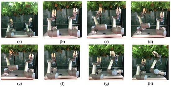
Figure 22.
The process of double-arm motion in the collision-prone region. (a) Initial location. (b) Collision detection. (c) Left robotic arm positioning fruit. (d) Left robotic arm picking fruit. (e) The left robot arm separates the fruit. (f) The left robot arm reaches the initial position. (g) The right robot arm grabs the fruit. (h) The right robot arm separates the fruit.
4. Conclusions
In this paper, a method of picking area planning and collision detection has been proposed against the collision problem in the cooperation of both robotic arms. The picking area division problem has been simplified into an MTSP. The simulation results have shown that compared with the GA-optimized multi-traveler algorithm, the total path length of the algorithm has been reduced by 32.31%, and the traversal time has been shortened by 46.9%.
For the collision detection problem between both robotic arms, we have determined the spatial coordinates of each joint space based on the robotic arm D–H parameters and the robotic arm kinematics. In order to simplify the model, capsule bodies and spheres have been used to envelop the robotic arm linkage and end-effector. The collision conditions between the joints, linkages, and end-effectors of the robotic arm have been simplified to the spatial relationship between the capsule body and the sphere, and between the capsule bodies. When the minimum distance between the two bounding boxes satisfies the corresponding constraints, it can be regarded that no collision occurs.
We have verified the feasibility of the proposed method by simulation and experimentation. The proposed zoning method has been used to optimize the picking sequence. The spatial relationship between the joints of the arms in the planned trajectory has been identified for collision at a time interval of 0.2 s. Secondary planning has been performed for the locations where collisions were likely to occur. The results have shown that the joint change during the robotic arm movement were smooth and satisfied the robotic arm movement limits. The proposed algorithm proved effective in detecting the collision position in the collision-prone subarea. The robotic arms were able to cooperate and implement effective obstacle avoidance at the same time, laying the foundation for the robotized picking of the picking robot at a later stage.
The main advantage of this study is collaborative kiwifruit harvesting with a double-arm, which provides the foundation for future work to improve harvesting efficiency. Future work should mainly include: (1) improving the accuracy of fruit identification and removing the interfering bands from sunlight to achieve the purpose of reducing the influence of light; (2) enhancing end-effector construction, such as implementing lightweight design of the end-effector; and (3) further improving the efficiency of fruit harvesting sequence planning by employing deep reinforcement learning.
Author Contributions
Conceptualization, Z.H.; methodology, Z.H. and L.M.; software, Y.W. (Yongzhe Wei); validation, Y.W. (Yinchu Wang); formal analysis, Z.H. and K.L.; investigation, X.D.; data curation, K.L.; writing—original draft preparation, Z.H.; writing—review and editing, Z.H. and X.D.; visualization, Z.H.; supervision, Y.W. (Yongzhe Wei); project administration, Y.C.; funding acquisition, Y.C. All authors have read and agreed to the published version of the manuscript.
Funding
This research was funded by National Natural Science Foundation of China, grant number 31971805.
Informed Consent Statement
Informed consent was obtained from all subjects involved in the study.
Data Availability Statement
All data are presented in this article in the form of figures and tables.
Acknowledgments
This study was conducted in the College of Mechanical and Electronic Engineering, Northwest A&F University.
Conflicts of Interest
The authors declare that they have no conflict of interest.
References
- Leontowicz, M.; Jesion, I.; Leontowicz, H.; Park, Y.S.; Namiesnik, J.; Rombolaì, A.D.; Weisz, M.; Gorinstein, S. Health-promoting effects of ethylene-treated kiwifruit “Hayward” from conventional and organic crops in rats fed an atherogenic diet. J. Agric. Food Chem. 2013, 61, 3661–3668. [Google Scholar] [CrossRef] [PubMed]
- Fazayeli, A.; Kamgar, S.; Mehdi, S.; Fazayeli, H.; Guardia, M. Dielectric spectroscopy as a potential technique for prediction of kiwifruit quality indices during storage. Inf. Process. Agric. 2019, 6, 479–486. [Google Scholar] [CrossRef]
- Yuan, J. Research progress analysis of robotics selective harvesting technologies. Trans. Chin. Soc. Agric. Mach. 2020, 51, 1–17. [Google Scholar]
- UN Food & Agriculture Organization. Production of Kiwi (Fruit) by Countries. Retrieved 2020-06-25; UN Food & Agriculture Organization: Rome, Italy, 2020. [Google Scholar]
- Zhao, C.J. Current situations and prospects of smart agriculture. J. S. Chin. Agric. Univ. 2021, 42, 1–7. [Google Scholar]
- Wang, Y.; Yang, Y.; Yang, C.; Zhao, H.; Chen, G.; Zhang, Z.; Fu, S.; Zhang, M.; Xu, H. End-effector with a bite mode for harvesting citrus fruit in random stalk orientation environment. Comput. Electron. Agric. 2019, 157, 454–470. [Google Scholar] [CrossRef]
- Bu, L.; Chen, C.; Hu, G.; Zhou, J.; Sugirbay, A.; Chen, J. Investigating the dynamic behavior of an apple branch-stem-fruit model using experimental and simulation analysis. Comput. Electron. Agric. 2021, 186, 106224. [Google Scholar] [CrossRef]
- Liu, J.Z.; Peng, Y.; Faheem, M. Experimental and theoretical analysis of fruit plucking pat-terns for robotic tomato harvesting. Comput. Electron. Agric. 2020, 173, 105330. [Google Scholar] [CrossRef]
- Fu, L.; Tola, E.; Al-Mallahi, A.; Li, R.; Cui, Y. A novel image processing algorithm to separate linearly clustered kiwifruits. Biosyst. Eng. 2019, 183, 184–195. [Google Scholar] [CrossRef]
- Wan, H.; Fan, Z.; Yu, X.; Kang, M.; Wang, P.; Zeng, X. A real-time branch detection and reconstruction mechanism for harvesting robot via convolutional neural network and image segmentation. Comput. Electron. Agric. 2022, 192, 106609. [Google Scholar] [CrossRef]
- Cao, X.; Zou, X.; Jia, C.; Chen, M.; Zeng, Z. RRT-based path planning for an intelligent litchi-picking manipulator. Comput. Electron. Agric. 2019, 156, 105–118. [Google Scholar] [CrossRef]
- Chen, Y.; Fu, Y.; Zhang, B.; Fu, W.; Shen, C. Path planning of the fruit tree pruning manipulator based on improved RRT-Connect algorithm. Int. J. Agric. Biol. Eng. 2022, 15, 177–188. [Google Scholar] [CrossRef]
- Mu, L.; Cui, G.; Liu, Y.; Cui, Y.; Fu, L.; Gejima, Y. Design and simulation of an integrated end-effector for picking kiwifruit by robot. Inf. Process. Agric. 2020, 7, 58–71. [Google Scholar] [CrossRef]
- Williams, H.; Nejati, M.; Hussein, S.; Penhall, N.; Lim, J.Y.; Jones, M.H.; Bell, J.; Ahn, H.S.; Bradley, S.; Schaare, P.; et al. Autonomous pollination of individual kiwifruit flowers: Toward a robotic kiwifruit pollinator. J. Field Robot. 2020, 37, 246–262. [Google Scholar] [CrossRef]
- Ling, X.; Zhao, Y.; Gong, L.; Liu, C.; Wang, T. Dual-arm cooperation and implementing for robotic harvesting tomato using binocular vision. Robot. Auton. Syst. 2019, 114, 134–143. [Google Scholar] [CrossRef]
- Li, T.; Qiu, Q.; Zhao, C.J.; Xie, F. Task planning of multi-arm harvesting robots for high-density dwarf orchards. Trans. Chin. Soc. Agric. Mach. 2021, 37, 1–10. [Google Scholar]
- Kahani, A. Multi-Robot Crop Harvesting Machine. U.S. Patent 9475189B2, 2 October 2022. [Google Scholar]
- Suo, R.; Gao, F.; Zhou, Z.; Fu, L.; Song, Z.; Dhupia, J.; Li, R.; Cui, Y. Improved mul-ti-classes kiwifruit detection in orchard to avoid collisions during robotic picking. Comput. Electron. Agric. 2021, 182, 106052. [Google Scholar] [CrossRef]
- Qi, R.; Wang, T. An obstacle avoidance trajectory planning scheme for space manipulators based on genetic algorithm. Robot 2014, 36, 263–270. [Google Scholar]
- Williams, H.; Jones, M.H.; Nejati, M.; Seabright, M.J.; Bell, J.; Penhall, N.D.; Barnett, J.J.; Duke, M.; Scarfe, A.J.; Ahn, H.S.; et al. Robotic kiwifruit harvesting using machine vision, convolutional neural networks, and robotic arms. Biosyst. Eng. 2019, 181, 140–156. [Google Scholar] [CrossRef]
- Xiong, Y.; Ge, Y.; Grimstad, L.; From, P.J. An autonomous strawberry-harvesting robot: Design, development, integration, and field evaluation. J. Field Robot 2020, 37, 202–224. [Google Scholar] [CrossRef]
- Lei, M.; Wang, T.; Yao, C.; Liu, H.; Wang, Z.; Deng, Y. Real-Time Kinematics-Based Self-Collision Avoidance Algorithm for Dual-Arm Robots. Appl. Sci. 2020, 10, 5893. [Google Scholar] [CrossRef]
- Wang, W.; Zhu, M.; Wang, X. An improved artificial potential field method of trajectory planning and obstacle avoidance for redundant manipulators. Int. J. Adv. Robot. Syst. 2018, 5, 128–135. [Google Scholar] [CrossRef]
- Fu, L.; Zhang, F.; Gejima, Y.; Li, Z.; Wang, B.; Cui, Y. Development and experiment of end-effector for kiwifruit harvesting robot. Trans. Chin. Soc. Agric. Mach. 2015, 46, 3. [Google Scholar]
- Safeea, M.; Mendes, N.; Neto, P. Minimum distance calculation for safe human robot interaction. Procedia Manuf. 2017, 11, 99–106. [Google Scholar] [CrossRef]
- Gao, G.; Sun, G.; Na, J.; Guo, Y.; Xing, W. Structural parameter identification for 6 DOF industrial robots. Mech. Syst. Signal Process. 2018, 113, 145–155. [Google Scholar] [CrossRef]
- Mu, L.T.; Gao, Z.B.; Cui, Y.J.; Li, K.; Liu, H.Z.; Fu, L.S. Kiwifruit detection of far-view and occluded fruit based on improved AlexNet. Trans. Chin. Soc. Agric. Mach. 2019, 50, 24–34. [Google Scholar]
- Wu, C.; Fu, X. An agglomerative greedy brain storm optimization algorithm for solving the TSP. IEEE Access 2020, 8, 201606–201621. [Google Scholar] [CrossRef]
- Shi, J.; Wang, D.; Shang, F.; Zhang, H. Research advances on stochastic gradient descent algorithms. Acta Auto Sin. 2021, 9, 2103–2119. [Google Scholar]
Publisher’s Note: MDPI stays neutral with regard to jurisdictional claims in published maps and institutional affiliations. |
© 2022 by the authors. Licensee MDPI, Basel, Switzerland. This article is an open access article distributed under the terms and conditions of the Creative Commons Attribution (CC BY) license (https://creativecommons.org/licenses/by/4.0/).