
Electric Heating System with Thermal Storage Units and Ceiling Fans for Cattle-Breeding Farms

 ,
,  and
and 
Abstract
1. Introduction
2. Materials and Methods
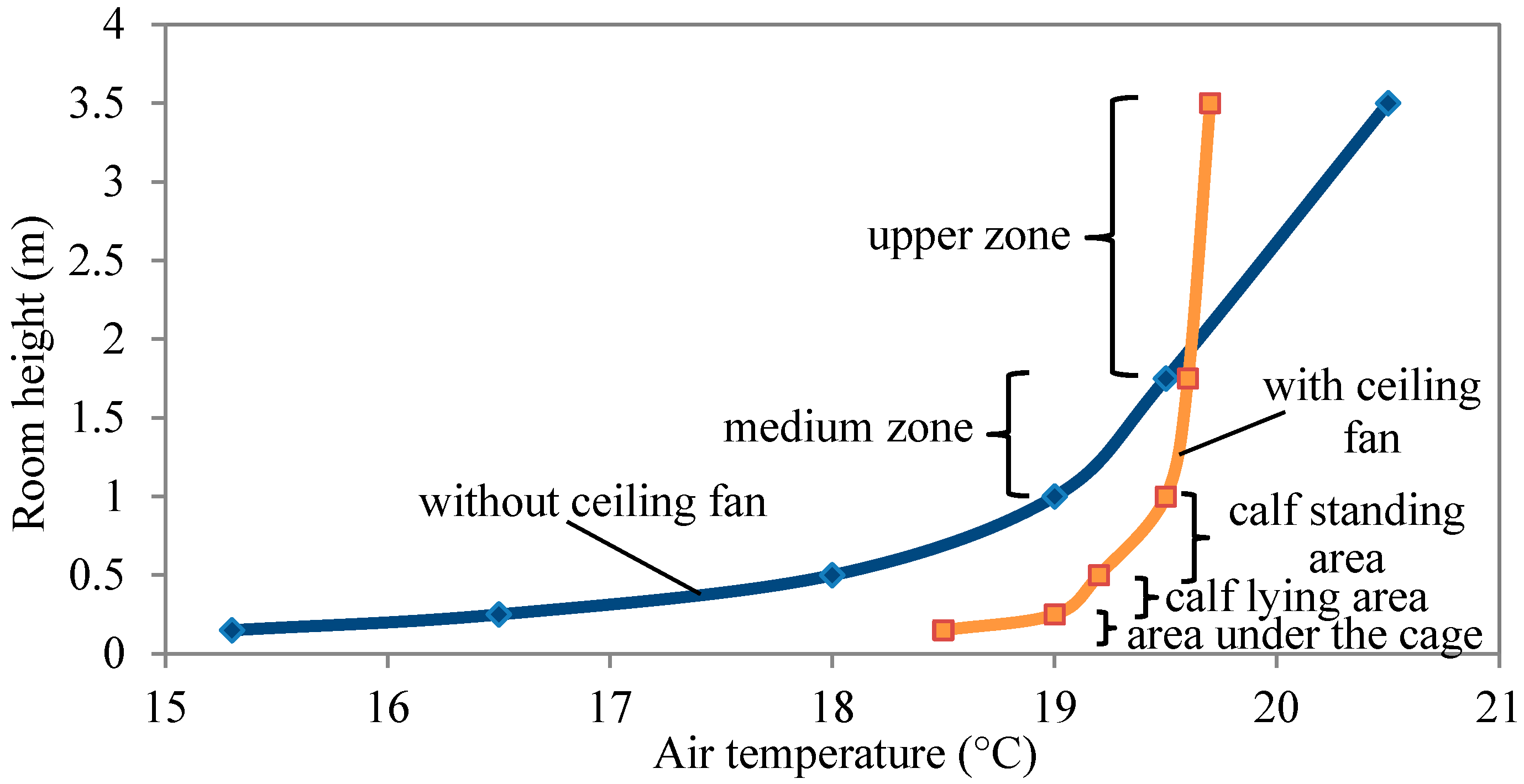
3. Calculating and Selecting the Ceiling Fan Parameters
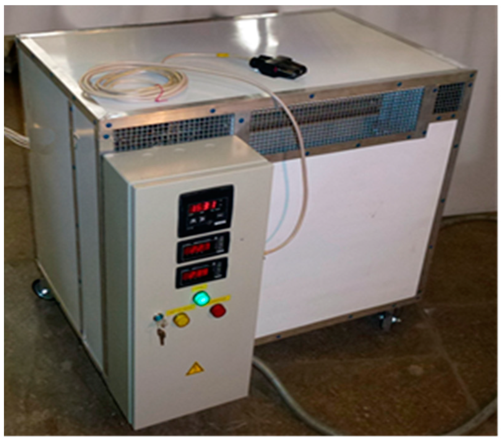
4. Calculating Basic Thermal Characteristics of the Electric Thermal Storage Unit
5. Discussion
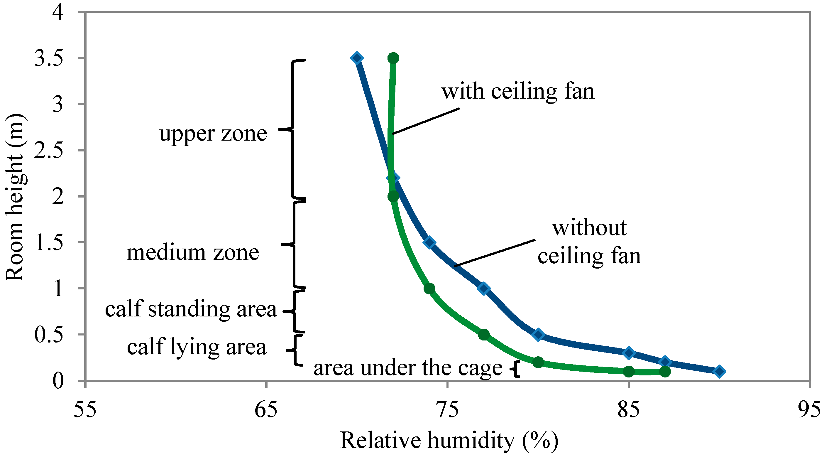
5.1. Experimental Studies of Thermal and Humidity Parameters of Air
5.2. Evaluation of the Energy Efficiency of the Combined Heat Supply System
6. Conclusions
Author Contributions
Funding
Institutional Review Board Statement
Informed Consent Statement
Data Availability Statement
Conflicts of Interest
References
- Roland, L.; Drillich, M.; Klein-Jobstl, D.; Iwersen, M. Invited review: Influence of climatic conditions on the development, performance, and health of calves. J. Dairy Sci. 2016, 99, 2438–2452. [Google Scholar] [CrossRef]
- López-Bellido, L.; Wery, J.; López-Bellido, R.J. Energy crops: Prospects in the context of sustainable agriculture. Eur. J. Agron. 2014, 60, 1–12. [Google Scholar] [CrossRef]
- Rastimeshin, S.A.; Trunov, S.S. Energy-Saving Systems and Technical Means for Heating and Ventilation in Cattle-Breeding Premises; FGBNU VIESH: Moscow, Russia, 2016. [Google Scholar]
- Li, J.; Qi, W.; Yang, J.; He, Y.; Luo, J.; Guo, S. The capacity optimization of wind-photovoltaic-thermal energy storage hybrid power system. E3S Web Conf. 2019, 118, 02054. [Google Scholar] [CrossRef]
- Sokolnikova, P.; Lombardi, P.; Arendarski, B.; Suslov, K.; Pantaleo, A.M.; Kranhold, M.; Komarnicki, P. Net-zero multi-energy systems for Siberian rural communities: A methodology to size thermal and electric storage units. Renew. Energy 2020, 155, 979–989. [Google Scholar] [CrossRef]
- Bruno, S.; Dicorato, M.; La Scala, M.; Sbrizzai, R.; Lombardi, P.A.; Arendarski, B. Optimal Sizing and Operation of Electric and Thermal Storage in a Net Zero Multi Energy System. Energies 2019, 12, 3389. [Google Scholar] [CrossRef]
- Dorjiev, S.S.; Bazarova, E.G.; Pimenov, S.V.; Rozenblum, M.I. Development of wind power installations with the accelerator of an air stream for areas with a low speed of wind. J. Phys. Conf. Ser. 2018, 1111, 012053. [Google Scholar] [CrossRef]
- Dorzhiev, S.S.; Bazarova, S.V.; Pimenov, S.V.; Dorzhiev, S.S. Application of renewable energy sources for water extraction from atmospheric air. Energy Rep. 2021, 7S5, 343–357. [Google Scholar] [CrossRef]
- Sun, Y.; Feng, Y.; Ma, Y.; Wang, Y.; Shi, Y. Thermal Storage and Release Features of Electric Thermal Storage Heating Systems with Solid Storage Material. Int. J. Heat Technol. 2019, 37, 1089–1098. [Google Scholar] [CrossRef]
- Zhao, H.; Yan, N.; Xing, Z.; Chen, L.; Jiang, L. Thermal Calculation and Experimental Investigation of Electric Heating and Solid Thermal Storage System. Energies 2020, 13, 5241. [Google Scholar] [CrossRef]
- Xing, Z.; Fu, Q.; Chen, L.; Xu, T. Research on multi-physical field coupling of solid electrothermal storage unit. Energy Rep. 2020, 6, 775–791. [Google Scholar] [CrossRef]
- Xu, G.; Hu, X.; Liao, Z.; Xu, C.; Yang, C.; Deng, Z. Experimental and Numerical Study of an Electrical Thermal Storage Device for Space Heating. Energies 2018, 11, 2180. [Google Scholar] [CrossRef]
- Klymchuk, O.; Denysova, A.; Shramenko, A.; Borysenko, K.; Ivanova, L. Theoretical and experimental investigation of the efficiency of the use of heat-accumulating material for heat supply systems. EUREKA Phys. Eng. 2019, 3, 32–40. [Google Scholar] [CrossRef][Green Version]
- Klymchuk, A.A.; Luzhanska, G.V.; Shramenko, A.N. Construction modernization of heat accumulators based on solid materials for electricity night tariffs operation. Refrig. Eng. Technol. 2017, 53, 44–48. [Google Scholar] [CrossRef]
- Beknazarian, D.V.; Kanevets, G.E.; Strogonov, K.V. Methodological bases of optimization of thermal insulation structures of glass furnaces. J. Phys. Conf. Ser. 2020, 1683, 052027. [Google Scholar] [CrossRef]
- Janssen, N.T.; Peterson, R.A.; Wies, R.W. Generalized heat flow model of a forced air electric thermal storage heater core. J. Therm. Sci. Eng. Appl. 2017, 9, 041008. [Google Scholar] [CrossRef]
- Pavlukhin, L.V.; Teterevnikov, V.N. Industrial Microclimate, Ventilation and Air Conditioning; Stroyizdat: Moscow, Russia, 1993. [Google Scholar]
- Qin, X.; Wang, D.; Jin, Z.; Wang, J.; Zhang, G.; Li, H. A comprehensive investigation on the effect of internal heat exchanger based on a novel evaluation method in the transcritical CO2 heat pump system. Renew. Energy 2021, 178, 574–586. [Google Scholar] [CrossRef]
- Qin, X.; Zhang, Y.; Wang, D.; Chen, J. System development and simulation investigation on a novel compression/ejection transcritical CO2 heat pump system for simultaneous cooling and heating. Energy Convers. Manag. 2022, 259, 115579. [Google Scholar] [CrossRef]
- RD-APK 1.10.01.01-18; Methodological Recommendations on Technological Design of Cattle-Breeding Farms and Complexes. Minselkhoz RF: Moscow, Russia, 2018.
- Bodrov, M.V. Justification, Selection and Calculation of Year-round Systems of Natural Ventilation in Livestock Premises. Sci. Her. Voronezh State Univ. Archit. Civ. Eng. Constr. Archit. 2011, 9, 1. [Google Scholar]
- Shah, N.; Sathaye, N.; Phadke, A.; Letschert, V. Efficiency improvement opportunities for ceiling fans. Energy Effic. 2015, 8, 37–50. [Google Scholar] [CrossRef]
- Babich, F.; Cook, M.; Loveday, D.; Rawal, R.; Shukla, Y. Transient three-dimensional CFD modelling of ceiling fans. Build. Environ. 2017, 123, 37–49. [Google Scholar] [CrossRef]
- Present, E.; Raftery, P.; Brager, G.; Graham, L.T. Ceiling fans in commercial buildings: In situ airspeeds & practitioner experience. Build. Environ. 2019, 147, 241–257. [Google Scholar] [CrossRef]
- Liu, S.; Lipczynska, A.; Schiavon, S.; Arens, E. Detailed experimental investigation of air speed field induced by ceiling fans. Build. Environ. 2018, 142, 342–360. [Google Scholar] [CrossRef]
- Raftery, P.; Fizer, J.; Chen, W.; He, Y.; Zhang, H.; Arens, E.; Schiavon, S.; Paliaga, G. Ceiling fans: Predicting indoor air speeds based on full scale laboratory measurements. Build. Environ. 2019, 155, 210–223. [Google Scholar] [CrossRef]
- Li, W.; Chong, A.; Hasama, T.; Xu, L.; Lasternas, B.; Tham, K.W.; Lam, K.P. Effects of ceiling fans on airborne transmission in an air-conditioned space. Build. Environ. 2021, 198, 107887. [Google Scholar] [CrossRef]
- Omrani, S.; Matour, S.; Bamdad, K.; Izadyar, N. Ceiling fans as ventilation assisting devices in buildings: A critical review. Build. Environ. 2021, 201, 108010. [Google Scholar] [CrossRef]
- Khimenko, A.V.; Tikhomirov, D.A.; Vasilyev, A.N.; Samarin, G.N.; Shepovalova, O.V. Numerical simulation of the thermal state and selecting the shape of air channels in heat-storage cells of electric-thermal storage. Energy Rep. 2022, 8, 1450–1463. [Google Scholar] [CrossRef]
- Khimenko, A.V.; Tikhomirov, D.A.; Kuzmichev, A.V.; Trunov, S.S.; Shepovalova, O.V. Thermal characteristics and operation efficiency of solid-state electro thermal storage. Energy Rep. 2021, 7, 219–231. [Google Scholar] [CrossRef]
- Tikhomirov, D.; Dudin, S.; Trunov, S.; Rastimeshin, S.; Tikhomirov, A.; Kuzmichov, A. Combined electric accumulation unit for air heating. Rev. De La Univ. Del Zulia 2019, 10, 168–183. [Google Scholar]
- Khimenko, A.V.; Tikhomirov, D.A.; Kuzmichev, A.V. Experimental studies of the thermal characteristics of electro-thermal storage. IOP Conf. Ser. Earth Environ. Sci. 2021, 839, 052058. [Google Scholar] [CrossRef]
- Khimenko, A.V.; Tikhomirov, D.A.; Kuzmichev, A.V.; Trunov, S.S. Experimental studies of the thermal state of heat storage units of electro thermal storage. IOP Conf. Ser. Earth Environ. Sci. 2021, 866, 012015. [Google Scholar] [CrossRef]
- Tikhomirov, D.A.; Khimenko, A.V.; Trunov, S.S.; Kuzmichev, A.V. Energy-saving automated IR heater for calves. IOP Conf. Ser. Earth Environ. Sci. 2021, 848, 012088. [Google Scholar] [CrossRef]
- Product Catalogue by Comp. Group ‘Euromash’. Ceiling Fans MR-1. Available online: https://www.evromash.ru/catalog/venti/pov/mr1/ (accessed on 16 August 2022).
- Shepelev, I.A. Aerodynamics of Air Flows in Premises; Stroyizdat: Moscow, Russia, 1978. [Google Scholar]
- Simonov, A.A. Household electric heating with heat storage is the most important factor in the efficient use of electricity. Energ. I Elektrif. 1992, 1, 26–30. [Google Scholar]
- Vysotskii, L.I. Electric Heaters of Storage Type; Informelectro: Moscow, Russia, 1971. [Google Scholar]
- Isachenko, V.P.; Osipova, V.A.; Sukomel, A.S. Heat Transfer, 4th ed.; Energoizdat: Moscow, Russia, 1981. [Google Scholar]
- Kutateladze, S.S.; Borishanskii, V.M. Handbook of Heat Transfer; Gosenergoizdat: Moscow, Russia, 1958. [Google Scholar]
- Kazantsev, E.I. Industrial Furnaces: Reference Guide for Calculations and Designing, 2nd ed.; Metallurgy: Moscow, Russia, 1975. [Google Scholar]
- Khimenko, A.V.; Prantsuz, O.S.; Glebova, I.A.; Ponomarev, A.K. Evaluation of the efficiency of heat storage by a solid-state electric thermal storage. J. Phys. Conf. Ser. 2020, 1560, 012049. [Google Scholar] [CrossRef]
- Klimenko, A.V.; Zorin, V.M. Thermal Energy Industry and Heat Engineering, 3rd ed.; MPEI Publishing: Moscow, Russia, 2004; Volume 4. [Google Scholar]
- Bogoslovskii, V.N. Thermal-Physics in Buildings (Thermal-Physical Principles of Heating, Ventilation and Air Conditioning): Guide-Book for Higher Education Institutes, 2nd ed.; Vysshaia shkola: Moscow, Russia, 1982. [Google Scholar]


| Input voltage (V) | 380/220 |
| Heat storage capacity (kW) | 4.8 |
| Electric convector heater capacity (kW) | 2.4 |
| Minimum heat charging period (h) | 4 |
| Heat emission period (h) | 48 |
| Weight (kg) | 200 |
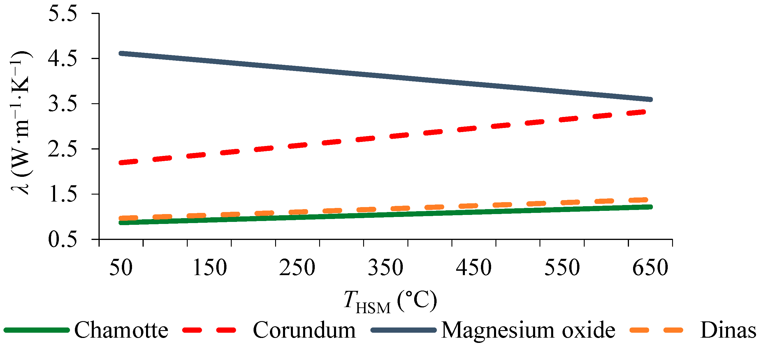
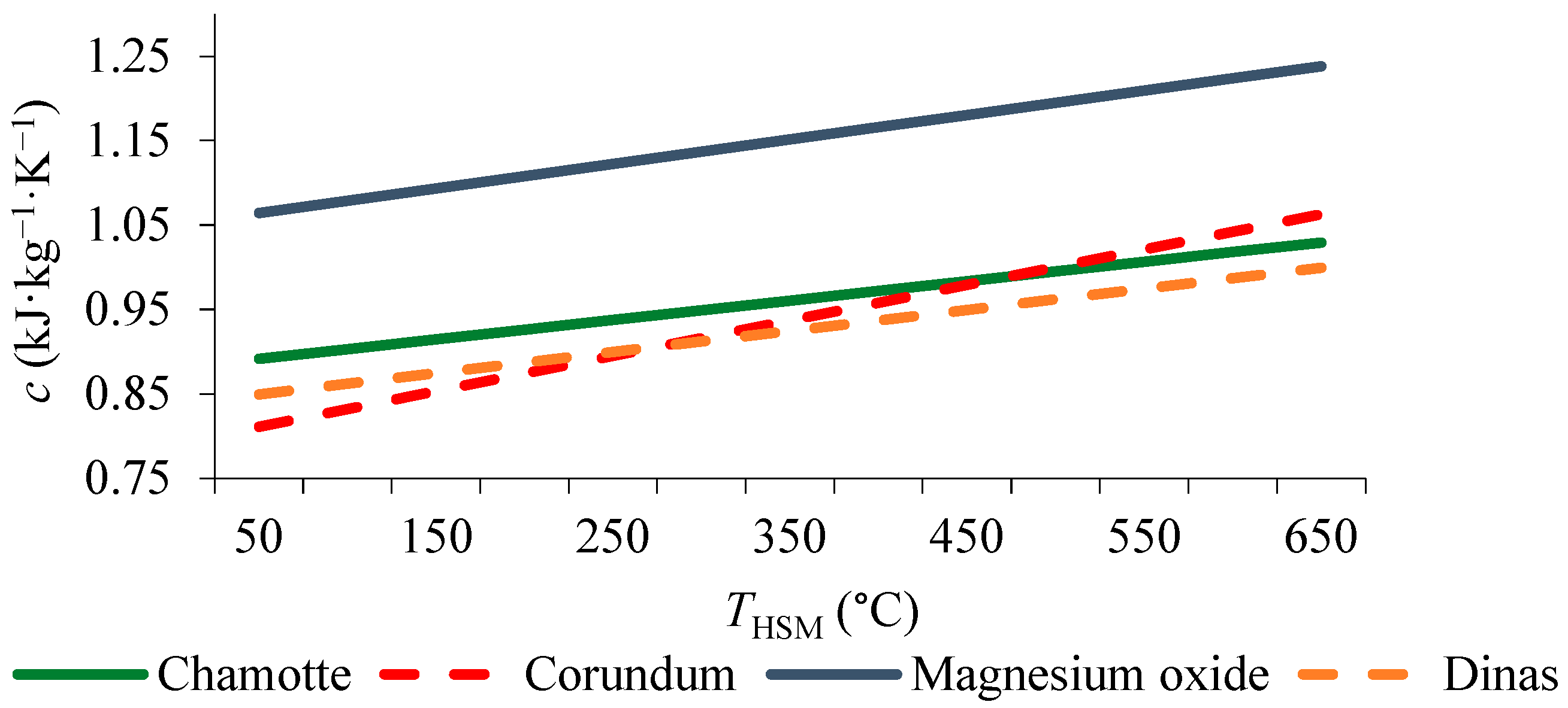
| Material | c (kJ·kg−1·°K−1) | λ (W·m−1·°K−1) | ρave (kg/m3) |
|---|---|---|---|
| Magnesium oxide | 1.05 + 0.29·10−3 THSM | 4.7–1.7·10−3 THSM | 3000 |
| Chamotte | 0.88 + 0.23·10−3 THSM | 0.84 + 0.58·10−3 THSM | 2200 |
| Corundum | 0.79 + 0.42·10−3 THSM | 2,1 + 1.9·10−3 THSM | 3300 |
| Dinas | 0.837 + 0.25·10−3 THSM | 0.93 + 0.69·10−3 THSM | 2200 |
Publisher’s Note: MDPI stays neutral with regard to jurisdictional claims in published maps and institutional affiliations. |
© 2022 by the authors. Licensee MDPI, Basel, Switzerland. This article is an open access article distributed under the terms and conditions of the Creative Commons Attribution (CC BY) license (https://creativecommons.org/licenses/by/4.0/).
Share and Cite
Khimenko, A.; Tikhomirov, D.; Trunov, S.; Kuzmichev, A.; Bolshev, V.; Shepovalova, O. Electric Heating System with Thermal Storage Units and Ceiling Fans for Cattle-Breeding Farms. Agriculture 2022, 12, 1753. https://doi.org/10.3390/agriculture12111753
Khimenko A, Tikhomirov D, Trunov S, Kuzmichev A, Bolshev V, Shepovalova O. Electric Heating System with Thermal Storage Units and Ceiling Fans for Cattle-Breeding Farms. Agriculture. 2022; 12(11):1753. https://doi.org/10.3390/agriculture12111753
Chicago/Turabian StyleKhimenko, Aleksei, Dmitry Tikhomirov, Stanislav Trunov, Aleksey Kuzmichev, Vadim Bolshev, and Olga Shepovalova. 2022. "Electric Heating System with Thermal Storage Units and Ceiling Fans for Cattle-Breeding Farms" Agriculture 12, no. 11: 1753. https://doi.org/10.3390/agriculture12111753
APA StyleKhimenko, A., Tikhomirov, D., Trunov, S., Kuzmichev, A., Bolshev, V., & Shepovalova, O. (2022). Electric Heating System with Thermal Storage Units and Ceiling Fans for Cattle-Breeding Farms. Agriculture, 12(11), 1753. https://doi.org/10.3390/agriculture12111753