Article

Design and Testing of Discrete Element-Based Counter-Rotating Excavation Device for Cyperus esculentus

1
College of Mechanical and Electronic Engineering, Shandong Agricultural University, Taian 271018, China
2
College of Mechanical and Electrical Engineering, Qingdao Agricultural University, Qingdao 266109, China
*
Author to whom correspondence should be addressed.
Agriculture 2022, 12(10), 1608; https://doi.org/10.3390/agriculture12101608
Submission received: 8 July 2022 / Revised: 9 September 2022 / Accepted: 29 September 2022 / Published: 4 October 2022
(This article belongs to the Section Agricultural Technology)

Abstract

:
Currently, the mechanized harvesting method of Cyperus esculentus is mainly based on rotary excavation, but there are problems such as high working resistance, high damage rate, and high buried fruit rate in the working process. This paper focuses on the analysis of the movement trajectory of the positive-rotating and counter-rotating Cyperus esculentus excavation device, establishes a agglomerate model of soil-Cyperus esculentus tuber-Cyperus esculentus root system-mechanism, and conducts discrete element simulation tests on Cyperus esculentus agglomerates under different soil layers. According to Expert test optimization, the optimal structural parameters of the counter-rotating blade are determined: the radius of gyration is 151 mm, the inclination angle of the cutting edge is 42.5°, and the working width is 318 mm. The comparative test of the positive-rotating rotary tillage method under the optimal structural parameters shows that the working resistance is reduced by 11.25%, and the torque of the tool shaft is reduced by 16.11%, which proves that the designed anti-rotation excavation structure has the effect of reducing resistance. To further test the harvesting performance of the Cyperus esculentus excavation device, field harvesting tests were conducted, and the results showed that the buried fruit rate of the counter-rotating excavation device was reduced by 11.6%, and the damage rate was reduced by 6.1% year-on-year. This study shows that the design of the counter-rotating excavation device can further improve the harvesting performance of Cyperus esculentus based on reduced resistance harvesting and meet the requirements of Cyperus esculentus harvesting.

1. Introduction

Cyperus esculentus is a herb native to Africa and Mediterranean coastal countries [1,2,3] and is a new economic crop that combines oil, food, pasture, forage, and ornamental greenery. It has wide adaptability, high oil content, and high nutritional value [4,5,6]. Currently, most areas in China are harvested with rotary tools, but there are problems such as high digging resistance, high buried fruit rate, and severe congestion [7,8], which cannot meet the requirements of large-scale harvesting of Cyperus esculentus.
The structural parameters of the excavation device play a decisive role in the quality and power consumption of the harvester [9], where the blade is the critical core component of the excavation device [10,11], which mainly achieves soil fragmentation and crop desorption from the soil during the harvesting operation. According to the harvesting requirements of different crops [12,13], there are also significant differences in structural parameters such as blade working depth, working width, inclination of the cutting edge, and working parameters [14,15,16]. The design of the operating depth of the excavation device is mainly based on the growth characteristics of different crops and has met the harvesting requirements of Cyperus esculentus [17], potatoes [18], peanuts [19], and other crops. In contrast, adding ultrasonic vibration devices to the excavation device can further reduce the working resistance and achieve better harvesting results [20,21,22,23]. The working width needs to be designed to meet the planting patterns of different crops [24,25], and some scholars have argued that the working width can be appropriately reduced in order to reduce the power consumption of the operation, but in the actual operation process, the working width is too small to cause serious fruit leakage [26,27]. The design of the inclination angle of the cutting edge should meet the essential physical characteristics of different crops [28]. In the harvesting process carried out on Cyperus esculentus [29], carrots [30], and other crops, in the design of the inclination angle of the cutting edge, some scholars appropriately increased the inclination angle of the cutting edge, which improved the performance of the soil entry, but reduced the working life of the tool to a certain extent [31].
However, current Cyperus esculentus excavation devices still suffer from high working resistance, high buried fruit rates, and high damage rates during harvesting, which reduces the harvesting efficiency of Cyperus esculentus.
In order to improve the harvest quality of Cyperus esculentus, this paper designs a Cyperus esculentus excavation device based on a counter-rotating operation, which focuses on the trajectory of the positive-rotating and counter-rotating Cyperus esculentus excavation device and establishes the Cyperus esculentus agglomerate model of soil-Cyperus esculentus tuber-Cyperus esculentus root system-mechanism, and carries out the discrete element experiments of Cyperus esculentus aggregates under different soil layers. In order to solve the problems of high working resistance, high fruit burial rate, and high damage rate in the process of Cyperus esculentus harvesting, the optimal structural parameters of the anti-rotation excavating device for Cyperus esculentus were determined by discrete element simulation and field harvesting tests.

2. Materials and Methods

2.1. Overall Structure and Working Principle

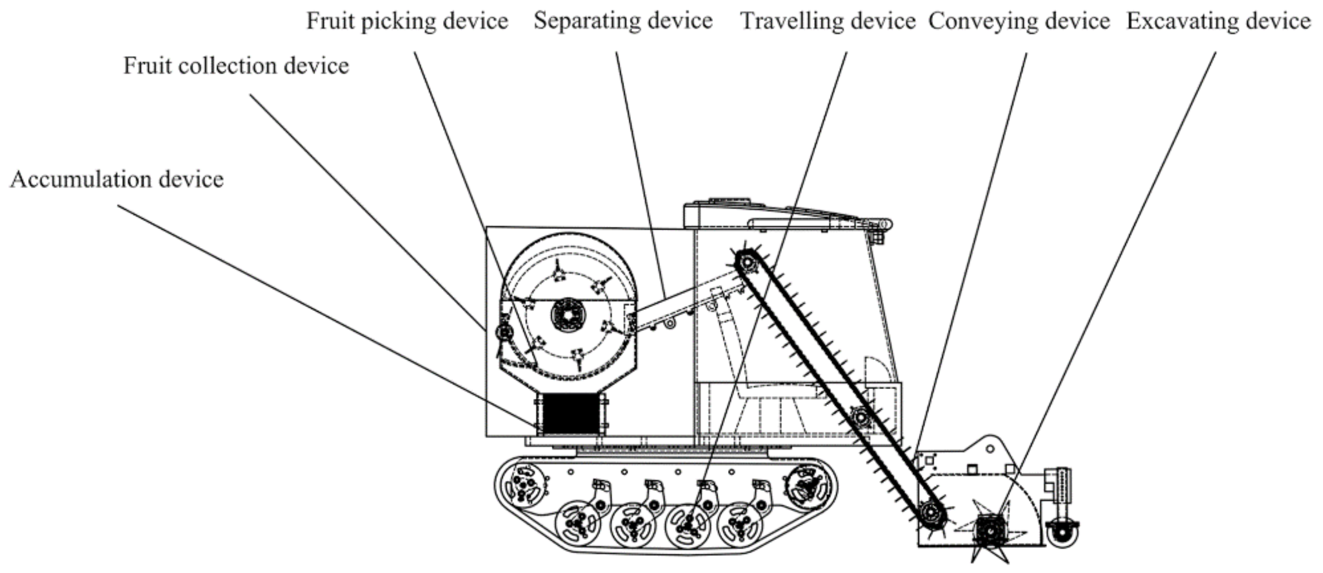
The Cyperus esculentus combine harvester mainly includes an excavating device, conveying device, soil-clearing device, fruit-picking device, fruit-collecting device, etc. It can complete the process of Cyperus esculentus excavating, conveying, fruit picking, clearing, and collecting at once, and the structure of the whole machine is shown in Figure 1.
In the process of Cyperus esculentus harvesting, the counter-rotation device sequentially performs the harvesting of the Cyperus esculentus from the tilled area to the uncultivated area. The Cyperus esculentus agglomerates are broken under the action of the counter-rotating blade, and are thrown from bottom to top along the tangential line of the counter-rotating cover plate, realizing the orderly transition between the excavating device and the conveying device. Under the action of the scraper-conveying device, the orderly conveying of the Cyperus esculentus agglomerates is realized; under the action of the fruit-picking device, the separation of the root system, the tuber and the soil is realized; and under the action of the cleaning device, the Cyperus esculentus tuber and impurities are separated. Finally, the collection device collects the tubers of Cyperus esculentus to the fruit collection box to complete the whole process of Cyperus esculentus.

Structure Parameters of Counter-Rotating Excavation Device

When the counter-rotating excavation device works, the rotation direction of the tool shaft is opposite to the rotation direction of the machine drive wheel, and the counter-rotating blade starts to cut the soil from the worked area to the unworked area, from the bottom to the ground. Due to the guiding effect of the soil hood, the Cyperus esculentus aggregates are thrown along the tangential direction of the soil hood to the conveying device for subsequent conveying of the Cyperus esculentus aggregates. The counter-rotating throwing device is shown in Figure 2 and main structural parameters are shown in Table 1.

2.2. Research on the Mechanism of Rotation Mode

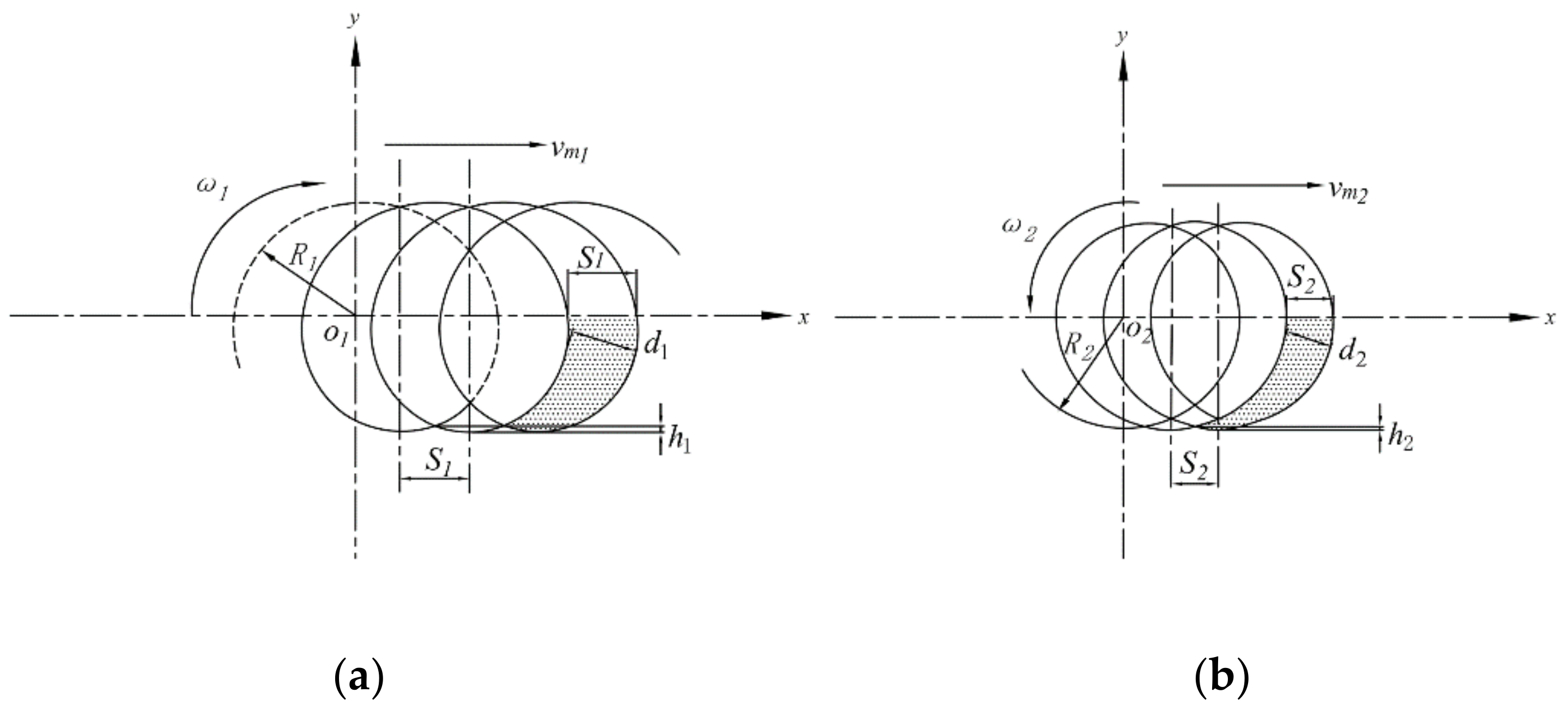
Currently, the commonly used excavation device for Cyperus esculentus mainly adopts the positive-rotating excavation method, but there are problems such as high buried fruit rate [2,29], low soil-breaking rate [18,29] and high working resistance during the operation [18,29]. In order to further determine the operation rotation method for Cyperus esculentus harvesting, the operation quality, such as endpoint speed, the thickness of the soil cube, and height of the bulge under different operation methods are compared and analyzed [2,18,29], as is shown in Figure 3.
Through the analysis of the positive-rotating and counter-rotating motion trajectories, the soil cutting speeds at the endpoints of positive-rotating and counter-rotating blades are obtained as follows [18]:
v 1 = v m 1 1 + λ 2 2 λ sin ω 1 t v 2 = v m 2 1 + λ 2 + 2 λ sin ω 2 t
where v1 is positive-rotating cutting soil speed, m/s; v2 is counter-rotating cutting soil speed, m/s; λ is rotary speed ratio; t is time, s.
Through the analysis of the positive-rotating and counter-rotating motion trajectory, the cutting thicknesses of the positive-rotating and counter-rotating soil are obtained as follows [25]:
d 1 = 2 π v m z 1 ω 1 sin λ cos ω 1 t λ 2 2 λ sin ω 1 t + 1 d 2 = 2 π v m z 2 ω 2 sin λ cos ω 2 t λ 2 + 2 λ sin ω 1 t + 1
where z1 is the number of blades in the same plane of positive rotation and z2 is the number of blades in the same plane of counter rotation.
Through the analysis of the f positive-rotating and counter-rotating motion trajectory, the heights of the bottom bulge of the positive-rotating and counter-rotating harvesting ditch are obtained as follows [25]:
h 1 = R 1 1 cos π z 1 λ 1 h 2 = R 2 1 cos π z 2 λ + 1
Combined with the motion trajectories and dynamics analysis of the positive-rotating and counter-rotating operations, the soil height after the reverse rotation operation is low and flat, which can ensure the stability of the tillage depth during the working process of the unit and reduce the impact of the counter-rotating tool shaft. Furthermore, the counter-rotating excavation increases the cutting speed, further improves the crushing quality of the Cyperus esculentus agglomerate, and reduces the working resistance of the counter-rotating blade.
The cutting amount of the counter-rotating excavation soil is small and stable, which further improves the soil fragmentation rate. At the same time, after the operation, the soil particles are distributed in layers, and the permeability is good, which is beneficial for the subsequent plowing and preparation.

2.3. Structural Parameter Analysis of Counter-Rotating Blade

Based on the analysis of the positive-rotating and counter-rotating operation process, this paper designs a reverse rotation excavation device for Cyperus esculentus, in which the counter-rotating blade is the key core component of the excavation device, and the structural parameters of the blade play a decisive role in the operation quality and power consumption of the harvester. In the process of harvesting, the counter-rotating blade mainly realizes soil crushing, Cyperus esculentus aggregate crushing and throwing. In this paper, a wide counter-rotating blade is designed, mainly consisting of key parameters such as the radius of gyration R, the inclination angle of the cutting edge β, the working width L, the shovel surface thickness M and the mounting hole spacing S, of which radius of gyration R, inclination angle of the cutting edge β and working width L are significant for harvest efficiency [2,18,29]. The structural parameter is schematically shown in Figure 4.

2.3.1. Design of Radius of Gyration R

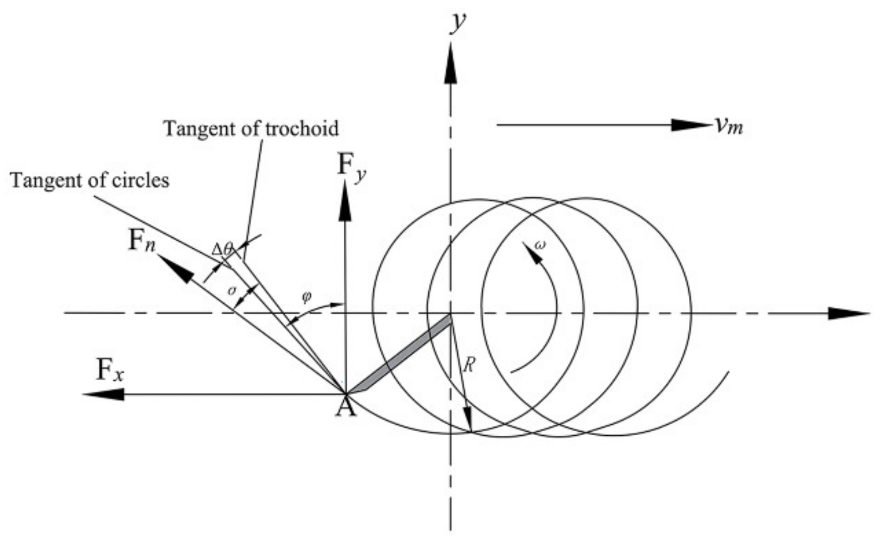
When the radius of gyration R is too large, the soil-breaking capacity and soil-throwing performance of the counter-rotating blade are enhanced, but the depth of the counter-rotating blade is too large, increasing working resistance during the working process [2,18,32]. The relevant studies have shown that the depth of the gyration radius of Cyperus esculentus is generally between 130~160 mm [32]. When the radius of gyration R is too small, the throwing performance of the Cyperus esculentus agglomerates will be reduced, resulting in a certain degree of fruit leakage and repeated excavation, resulting in lower harvest quality and additional power consumption. In this paper, the design of the radius of gyration R is carried out based on the force relationship of the counter-rotating blade during the excavation process, as shown in Figure 5.
F x = F n sin ( φ + σ Δ θ )
F y = F n cos ( φ + σ Δ θ )
F n = ρ 2 π R z λ sin λ cos φ λ 2 2 λ sin φ + 1 L
From Equation (6), it can be seen that the working resistance of the counter-rotating blade in the process of counter-rotating and throwing Cyperus esculentus agglomerates is proportional to the radius of gyration R [25]. Field tests have shown that the resultant depth of Cyperus esculentus is generally between 93~138 mm. In this paper, under the premise of fully considering the working resistance, the radius of gyration R is initially set to 140~180 mm.
The forward speed of the machine from cutting the soil to throwing the soil should meet the following conditions [25,32]:
x = R cos ω t + V m t y = R sin ω t = R h
To further ensure the throwing of Cyperus esculentus agglomerates, the horizontal component of the velocity at the end point of the blade should satisfy Vx < 0. The following conclusion is obtained [25,32]:
V x = d x d t = V m R ω sin ω t sin ω t = R R L
In order to ensure that the forward speed of the machine meets the gyration radius of cutting soil, combined with the Cyperus esculentus planting pattern and the actual growth state, the forward speed of the machine should meet the following conditions [25,32]:
V m < R 2 ω R L
where L is the actual depth of growth of Cyperus esculentus.

2.3.2. Design of Inclination Angle of Cutting Edge β

When the inclination angle of cutting edge β is too large, the soil entry performance decreases during the excavation process, resulting in weeds not being removed in time, while the performance of the soil-breaking rate decreases, resulting in the Cyperus esculentus agglomerates being congested in front of the shovel [18,19]. The relevant studies have shown that the depth of the inclination angle of cutting edge of Cyperus esculentus is generally between 30~60° [18]. When the inclination angle of cutting edge β is too small, the soil entry performance and weed cutting performance are enhanced, but too small an inclination angle of the blade will increase the length of the shovel tip to a certain extent, quickly causing wear and damage to the shovel tip during work [18,19]. To further ensure that the counter-rotating blade automatically cleans the shovel surface during the harvesting process and that the slip-cutting of Cyperus esculentus agglomerates on the shovel surface can reduce the role of friction, this paper combines Equations (5) and (6) and references the relevant literature [18,19,21] to set the value of the inclination angle of cutting edge of the counter-rotating blade to 35–65° initially:
P × cos β F
where P is resistance to the inclination angle of the cutting edge of the blade, N; F is friction between the inclination angle of cutting edge of blade and the soil, N.

2.3.3. Design of Working Width L

When the working width L of the counter-rotating blades is too small, serious fruit leakage will occur, reducing the harvesting efficiency [13,18]. When the working width L increases, the installation distance of the counter-rotating blades will be increased to a certain extent, reducing the total number of counter-rotating blades [13,18,33]. However, too large a working width L will lead to the crushing quality of the Cyperus esculentus agglomerates and will also increase the working resistance of the counter-rotating blades, increasing the power consumption.
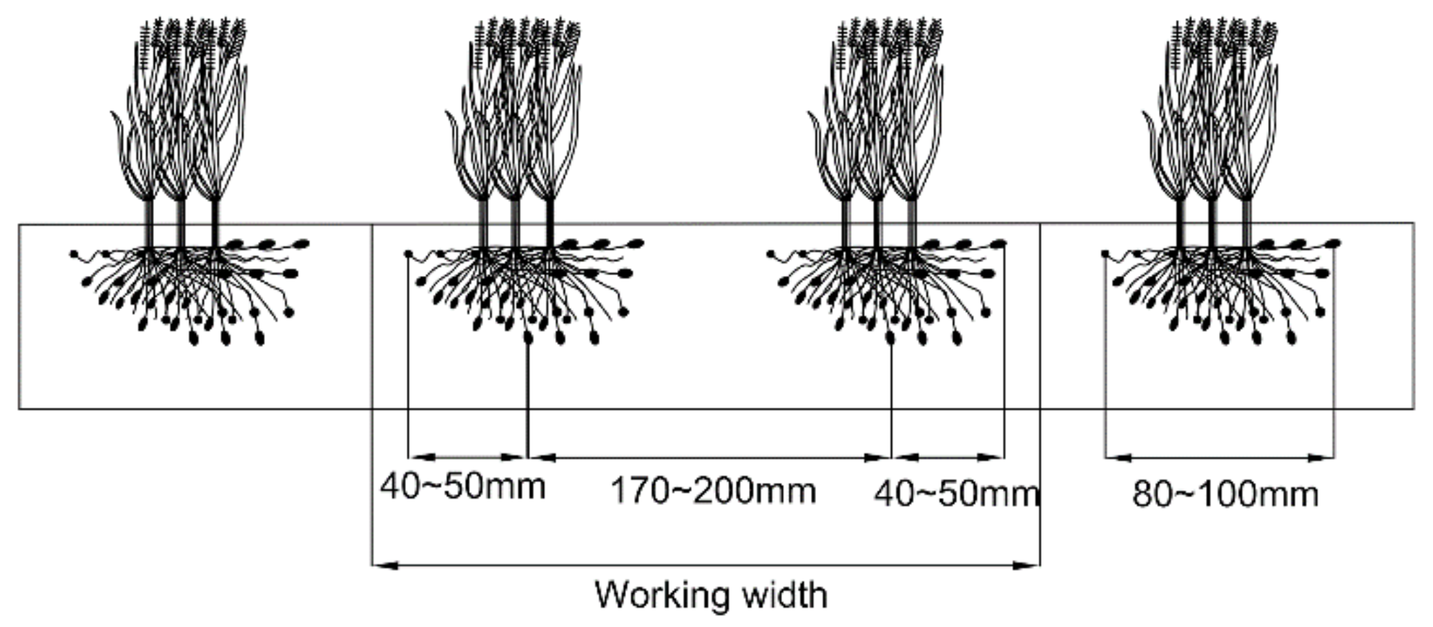
Field tests show that the width of the underground results of Cyperus esculentus is generally 80~100 mm. In order to ensure that the working width of the blade is reversed to complete the two rows of Cyperus esculentus harvest, this paper combines the Cyperus esculentus planting mode and considers the relationship between the working width of Equation (6) on the working resistance and the Cyperus esculentus planting row spacing of 170~200 mm in Henan Province, China. Moreover, the working width of the counter-rotating blade is initially set to 300~340 mm, as shown in Figure 6.

2.4. Discrete Element Simulation Modeling

2.4.1. Discrete Element Model for Soil

Related studies have shown that the computational precision of the simulation decreases geometrically when the radius of the soil particle model increases [33,34]. In order to improve the accuracy of the discrete element simulation test, this paper establishes the soil particle bed model with the mean value of parameters. Under the premise of ensuring the test accuracy, the soil particles are appropriately enlarged, and the soil particle radius is set to 2.5 mm. Moreover, the soil particle model is set to the following four models using the particle combination of [35,36]: single grain spherical model (5 mm × 5 mm × 5 mm), three-grain flake model (8.55 mm × 8 mm × 5 mm), four-grain block model (8.55 mm × 8 mm × 8 mm), and four-grain rod model (12.5 mm × 5 mm × 5 mm), as shown in Figure 7.

2.4.2. Discrete Element Model of Cyperus esculentus Tubers

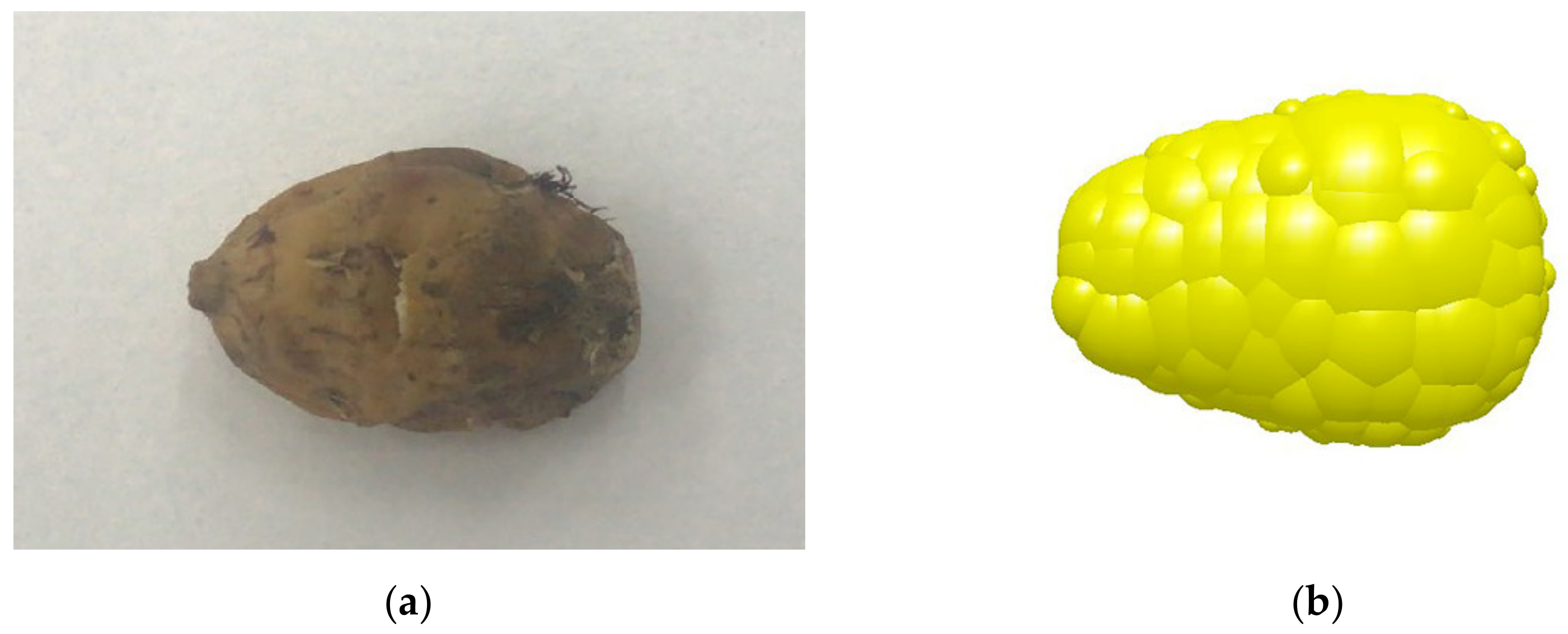
Cyperus esculentus tubers are characterized by different sizes and irregular shapes [37], and in the actual field harvesting operation of Cyperus esculentus, Cyperus esculentus tubers are one of the leading research objects of Cyperus esculentus agglomerates. In order to improve the accuracy and scientificity of discrete element simulation and further analyze the movement of Cyperus esculentus tubers during the harvesting process, this paper combines the 3D tests of Cyperus esculentus tubers and uses 3D software for the three-dimensional contour of the tuber constructed, and then the model of the tuber was saved in STL format and imported into EDEM2020 for particle filling, and the three-axis dimensions of the filled Cyperus esculentus were 15 mm in length, 12 mm in width and 9 mm in height. The discrete element model of the Cyperus esculentus tubers is shown in Figure 8.

2.4.3. Discrete Element Model of Cyperus esculentus Root System

In order to improve the accuracy of the simulation test and accurately simulate the contact relationship between the root system of Cyperus esculentus, Cyperus esculentus tubers and soil, this paper combines the actual physical characteristics of the root system of Cyperus esculentus and simplifies the modeling of the root system of Cyperus esculentus. A discrete element model of the rigid body of the root system was constructed. In this paper, the upper part of the root system was composed of 8 mm diameter discrete element particles with 4 mm spherical spacing, and the root system was composed of 3 mm diameter discrete element particles with 1.5 mm spherical spacing, and a total of 219 discrete element particles were used to form a 160 mm long root system. The discrete element model of the Cyperus esculentus root system is shown in Figure 9.

2.5. Contact Modelling and Parameterisation

2.5.1. Contact Model

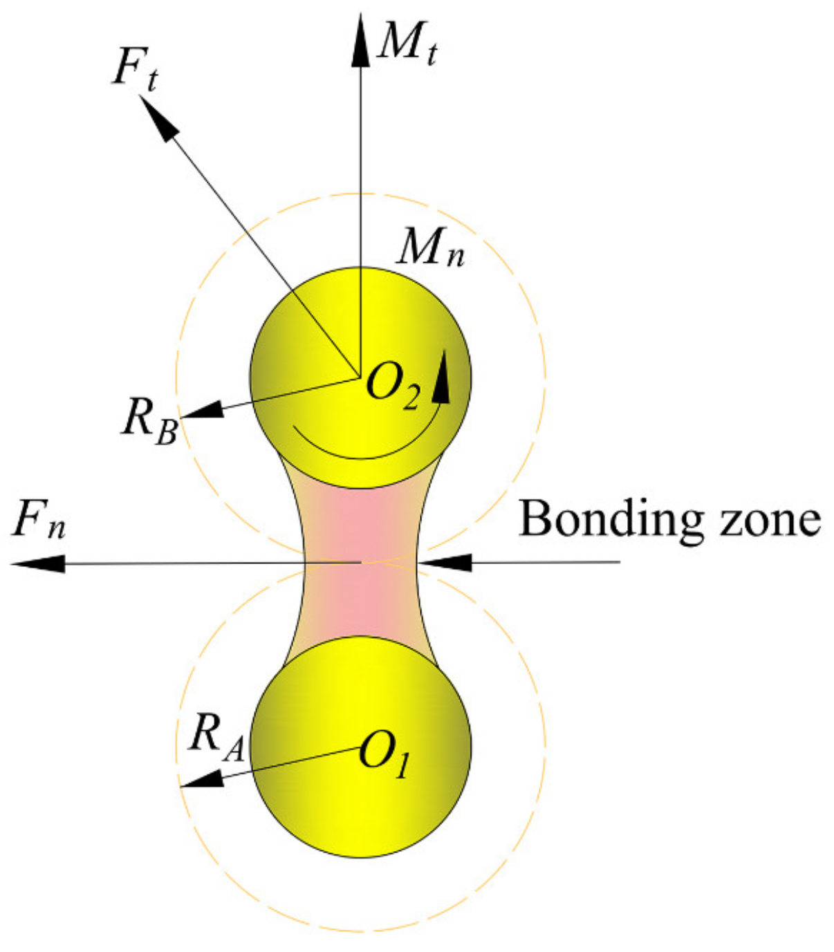
To accurately simulate the cohesive soil properties in the Minquan area of Henan Province, the Hertz-Mindlin with Bonding model was chosen for the contact model between soil particles, as shown in Figure 10, which can bond two adjacent soil particles together by bonding force, and the bonding force can withstand tangential and normal displacements [38,39,40]. In the actual field operation process, there are adhesion forces between soil and soil, and there is a forced relationship between the excavation shovel and soil. Additionally, this model can simulate the bonding action between soil particles and the phenomenon of soil particle fragmentation.
When soil particles are bonded, the following relationships exist [2,29]:
δ F n = v n k n A δ t δ F t = v t k t A δ t δ T n = ω n k t A δ t δ T t = ω t k t j 2 δ t
where Vn is normal velocity, m/s; Vt is tangential velocity, m/s; kn is normal stiffness, N/m; kt is tangential stiffness, N/m; A is unit contact area, mm2; J is moment of inertia, mm4; and δt is time step, s.
Bonding between soil particles will break when the normal and tangential stresses reach specific extreme values; when the bond breaks, the following relationships exist [2,29]:
σ max < F n A + 2 M t J R B τ max < F t A + M n J R B
where σmax is normal stress, N; τmax is tangential stress, N; and RB is radius of particle bonding, mm.

2.5.2. Discrete Element Parameters Setting

In order to ensure the accuracy of the simulation tests, the contact parameters and basic physical parameters involved in the simulation tests were determined in this paper through parametric tests and a review of the literature [2,29,41,42], as shown in Table 2 and Table 3.

2.5.3. Cyperus esculentus Agglomerate Modelling

In the simulation test, the rotational speed of the tool shaft was set to 350 r/min, and the forward speed was set to 0.4 m/s. The inclination angle of the cutting edge was set to 50°, the radius of gyration was set to 180 mm, the working width was set to 320 mm, and the total simulation test was set to 5 s. To improve the accuracy of the simulation test, in the Cyperus esculentus agglomerates factory of EDEM, the parameters for the location of the Cyperus esculentus root system were set and the position type was cubic, the row spacing of Cyperus esculentus was set to 170 mm and the plant spacing was set to 150 mm, and the Cyperus esculentus agglomerates were stratified according to different depths of the soil, where 0–50 mm was the shallow soil, 50–150 mm was the middle soil and 150–200 mm was the deep soil. The model is shown in Figure 11a, and the vector model of the Cyperus esculentus agglomerate is shown in Figure 11b.

2.6. Discrete Element Simulation

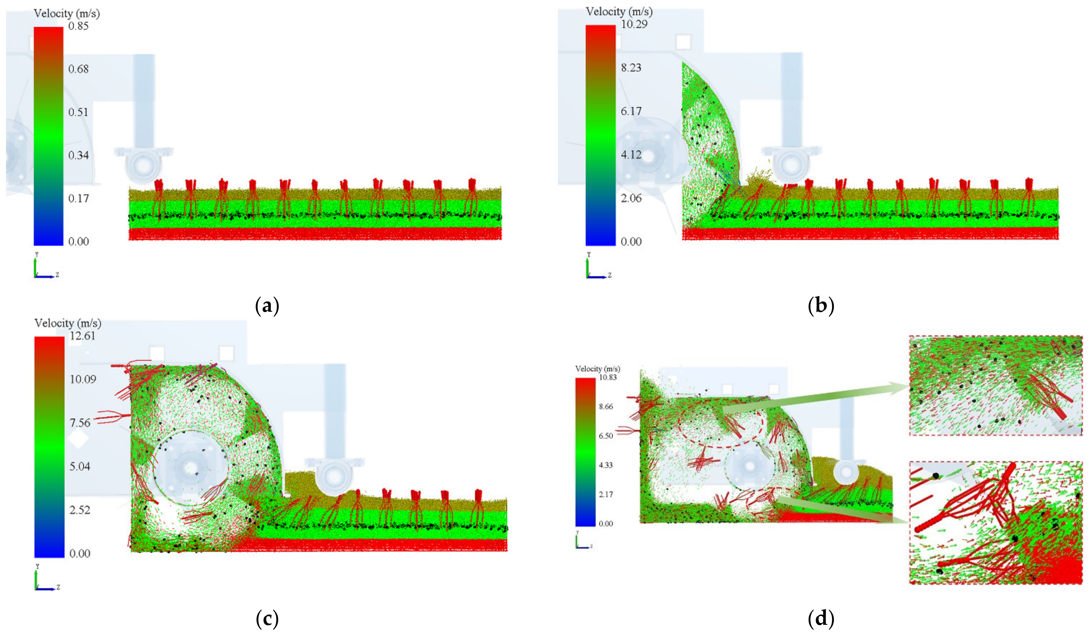
Figure 12 shows the vector diagram of the movement of the Cyperus esculentus agglomerates at different moments of the simulation test, as shown in Figure 12a. At the moment of 2 s, when the counter-rotating blade just touched the Cyperus esculentus agglomerates, the shallow soil was disturbed by the counter-rotating blade, and the soil moved along the tangential direction of the retaining hood plate. With the compound movement of the counter-rotating blade shaft, the counter-rotating blade began excavating and throwing the Cyperus esculentus agglomerates, as shown in Figure 12b. At this time, the counter-rotating blade made counter-rotating throwing movements from bottom to top, from far to near, contacting the Cyperus esculentus agglomerates in the deep, middle, and shallow layers in turn. At the same time, in the unworked area disturbed by the counter-rotating blades in the working area, the shallow and middle layers of soil and Cyperus esculentus agglomerates at the outer edge of the baffle plate tended to bulge upwards. As shown in Figure 12c,d, a continuous flow of Cyperus esculentus tubers, roots, and soil agglomerates along the tangential movement was formed at the end of the baffle plate, which is conducive to the transport of Cyperus esculentus agglomerates by the conveying device and to a certain extent. At the same time, the different soil layers in the post-operation area were thoroughly mixed, which laterally reflects the better soil-breaking performance of the counter-rotating throwing device.

2.7. Field Trials

2.7.1. Field Trial Conditions

In order to further test the harvesting performance of the anti-rotation excavation device for Cyperus esculentus, this paper refers to the NY/T 502-2016 harvesting standard, and conducts field experiments based on the evaluation indicators of the buried fruit rate Y3 and the damage rate Y4. The test site was selected as the Cyperus esculentus planting base in Minquan County, Henan Province. In this area, the row spacing of the Cyperus esculentus planting model was 170 mm, the plant spacing was 150 mm, as shown in Figure 13a, and the growth depth of the Cyperus esculentus was about 140 mm, as shown in Figure 13b. The soil parameter table is shown in Table 4.
Y 3 = m 2 m 1 + m 2 + m 3 × 100 %
Y 4 = m 4 m 1 + m 2 + m 3 × 100 %
where Y3 is the fruit burial rate of Cyperus esculentus, %; Y4 is the damage rate of Cyperus esculentus, %; m1 is the mass of Cyperus esculentus tubers on the ground in the test area, g; m2 is the mass of Cyperus esculentus tubers buried in the soil in the test area, g; m3 is the mass of Cyperus esculentus tubers harvested from the test area, g; and m4 is the mass of damaged Cyperus esculentus tubers harvested from the test area, g.

2.7.2. Field Trial Program

The test equipment mainly included a TM-85 soil density meter (Beijing Aerospace Huayu Experimental Instruments Ltd., Beijing, China), TJSD-750-IV soil compaction meter (Zhejiang Tuoyunong Technology Ltd., Hangzhou, Zhejiang, China), WKT-M1 soil moisture meter (Jiangsu Weikite Instruments Ltd., Changzhou, Jiangsu, China), WT-CF series high-precision electronic scales (Changzhou Wantai Balance Instruments Ltd., Changzhou, Jiangsu, China), steel frame tape measure (Hunan Maojun Baogong Electronics Ltd., Changsha, China, range: 0~150 m, accuracy: 1 mm), meter ruler (range: 0~5 m, accuracy: 1 mm), and excavation shovel.
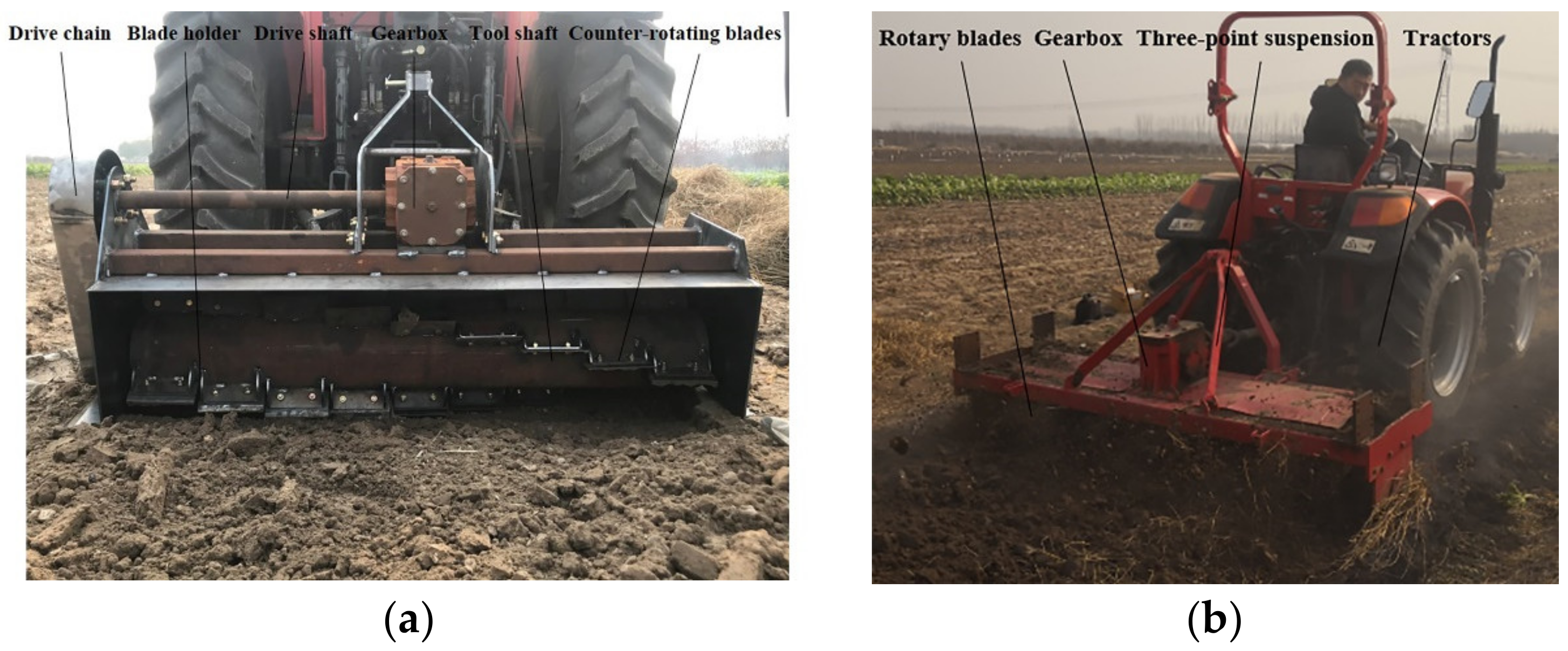
The test was divided into five areas, the length of each test area was 50 m, the machine operating speed was set to 0.5 m/s, and the counter-rotating excavation device, as shown in Figure 14a, and the positive-rotating excavation device, as shown in Figure 14b were, respectively, attached to the Dongfeng DF604 tractor (Changzhou Dongfeng Agricultural Machinery Group Ltd., Changzhou, China, matching power: 60 hp)), to carry out a comparative analysis of the harvesting performance of Cyperus esculentus.

3. Results and Analysis

3.1. Analysis of Simulation Tests for Single Factor

In order to further determine the value range of the factors affecting the quality of the Cyperus esculentus operation, the radius of gyration R, the inclination angle of cutting edge β and the working width L were used as the test factors, and the working resistance Y1 and the torque of the tool shaft Y2 were used as the evaluation indicators. Theoretical analysis of the range of values was performed with single factor experiments, which provided a theoretical basis for subsequent multifactor experiments.

3.1.1. Influence of Radius of Gyration R on Evaluation Indicators

With a fixed counter-rotating excavation device with a forward speed of 0.8 m/s, a tool shaft speed of 40 rad/s, a inclination angle of cutting edge of 50°, a working width of 320 mm, and a radius of gyration of 140 mm, 150 mm, 160 mm, 170 mm and 180 mm, respectively, five sets of simulations were carried out and the test results are shown in Figure 15A. The test results show that the change of gyration radius significantly impacts the working resistance and tool shaft torque; as the radius of gyration increases between 140~150 mm, the working resistance and tool shaft torque drops sharply, further illustrating the effect of the radius of gyration on working resistance and tool shaft torque. As the radius of gyration increases between 150~170 mm, the variation of the working resistance value and tool shaft torque is relatively gentle, indicating that this interval is the effective value range of the radius of gyration. As the radius of gyration increases between 170~180 mm, the working resistance value rises sharply. In order to further determine the best value of the counter-rotating blade radius of gyration, the radius of gyration of 150~170 mm was selected for subsequent multi-factor tests.

3.1.2. Influence of Inclination Angle of Cutting Edge β on Evaluation Indicators

The fixed counter-rotating excavation device has a forward speed of 0.8 m/s, a tool shaft speed of 40 rad/s, a radius of gyration of 160 mm, a working width of 320 mm, and a inclination angle of cutting edge of 35°, 42.5°, 50°, 57.5°, and 65°, respectively. Five sets of simulation tests were carried out, and the test results are shown in Figure 15B. The test results show that the change of the inclination angle of the cutting edge significantly impacts the working resistance and tool shaft torque. When the inclination angle of the cutting edge is between 35~42.5°, the working resistance drops sharply, further illustrating the effect of inclination angle of cutting edge on working resistance. When the inclination angle of the cutting edge is between 42.5~57.5°, the tool shaft torque and the working resistance change more smoothly; in order to determine further the optimum value of the counter-rotating inclination angle of the cutting edge, the inclination angle of cutting edge of 42.5–57.5° was selected for subsequent multifactor tests.

3.1.3. Influence of Working Width L on Evaluation Indicators

The results of the five simulation tests with a fixed counter-rotating excavation device forward speed of 0.8 m/s, tool shaft speed of 40 rad/s, the radius of gyration selected as 160 mm, the inclination angle of cutting edge selected as 50°, the working width taken as 300 mm, 310 mm, 320 mm, 330 mm, and 340 mm, respectively, are shown in Figure 15C. The test results show that the change in working width significantly affects the working resistance and tool shaft torque. As the working width increases, the soil contact area of the blade also increases, resulting in a large variation of working resistance and tool shaft torque during the harvesting process of Cyperus esculentus. As the working width increases between 300~310 mm, the working resistance and tool shaft torque drops sharply, further illustrating the effect of radius of gyration on working resistance and tool shaft torque. As the working width increases between 310~330 mm, the variation of the working resistance value and tool shaft torque is relatively gentle, indicating that this interval is the effective value range of the radius of gyration. As the working width increases between 330~340 mm, the working resistance value rises sharply. In order to further determine the best value of the counter-rotating blade working width, the working width of 310~330 mm was selected for subsequent multi-factor tests.

3.2. Analysis of Simulation Tests for Multi-Factors

3.2.1. Test Factor Codes

In order to obtain the ideal counter-rotating blade structure parameters, the EDEM orthogonal rotation virtual simulation experimental study was carried out. Combined with the range of values of the previous test factors, the test factor codes were set as shown in Table 5.

3.2.2. Multi-Factor Test Results and Analysis

A three-factor, three-level quadratic regression orthogonal test was carried out with radius of gyration R, inclination angle of cutting edge β, and working width L as test factors, and working resistance and cutter shaft torque as evaluation indicators. The results were analyzed according to the obtained data, and the significance analysis of the main factors affecting the index was carried out. The test results are shown in Table 6.

3.2.3. The Relationship between Test Factors and Working Resistance

According to the analysis of Table 7, the coefficient of determination was R2 = 0.9579, indicating that the regression equation model was suitable for 95.79% of the test data. When p < 0.01, it means that the regression model has a very significant influence; the radius of gyration (A), the inclination angle of the cutting edge (B), and the working width (C) have a very significant influence on the working resistance, and the interaction terms of the radius of gyration (A2), the inclination angle of the cutting edge (B2) and the radius of gyration (C2) have a very significant influence on the working resistance. In a comprehensive analysis, the order of the degree of influence on the working resistance of Cyperus esculentus harvesting is working width (C) > inclination angle of cutting edge (B) > radius of gyration (A).
After removing the non-significant factors, according to the working resistance variance in Table 7, the quadratic polynomial regression equation of the working resistance of Cyperus esculentus harvesting was obtained.
Y 1 = 1736.39 + 49.91 A + 90.28 B + 75.87 C 119.83 A 2 77.46 B 2 + 90.82 C 2
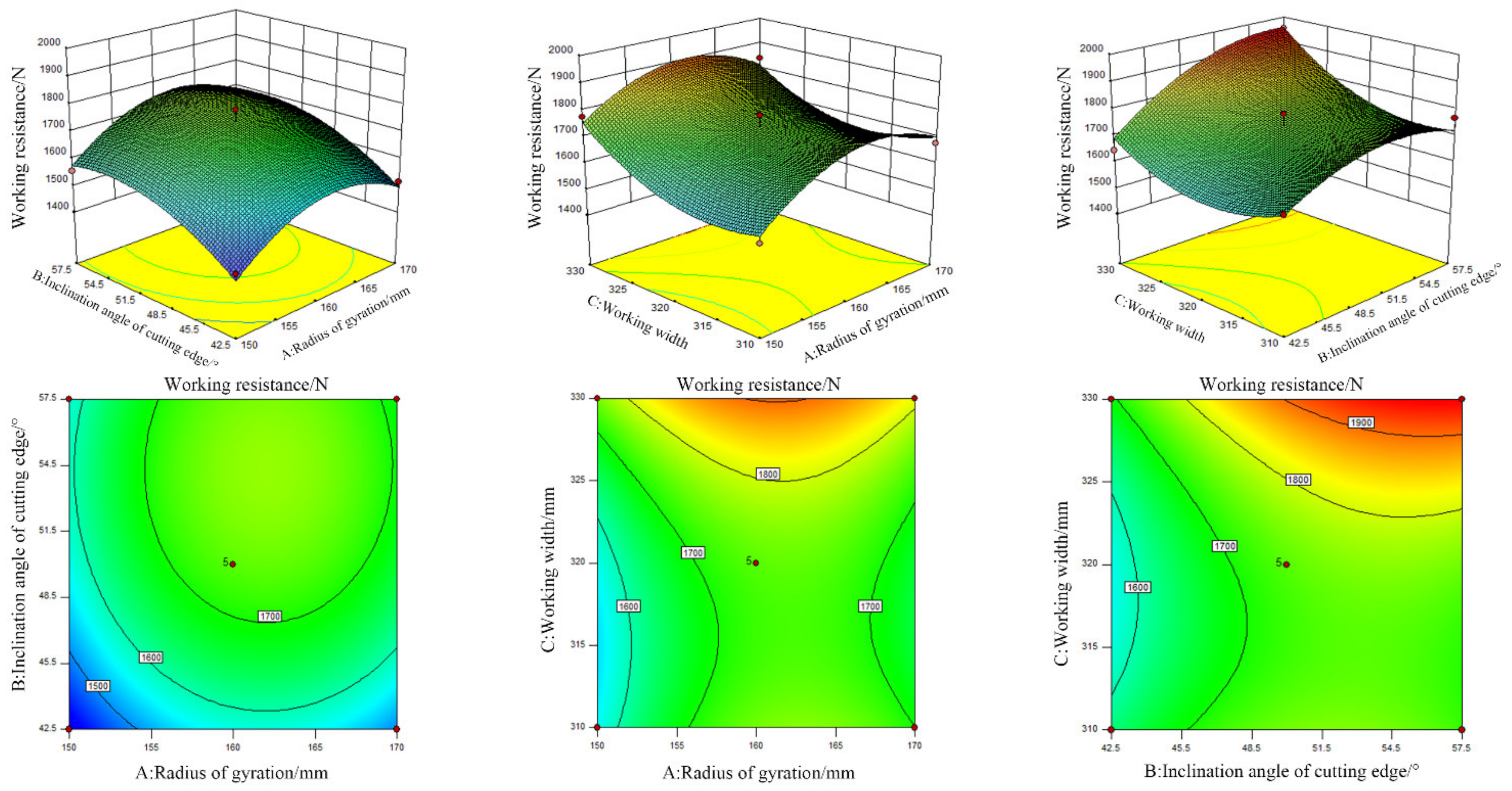
The effect of the test factors radius of gyration R, inclination angle of cutting edge β, and working width L on the working resistance of Cyperus esculentus harvesting is shown in Figure 16. In the interval of −1~0.25, the working resistance gradually increases in the interval of 1566~1744 N and the growth rate gradually decreases with the gradual increase of the level of the radius of the gyration R factor. Since the root system of Cyperus esculentus is mainly concentrated in the underground at about 150 mm, this leads to higher soil solidity around Cyperus esculentus agglomerates than other soil layers, and in the harvesting process the counter-rotating blade has to realize the harvesting process, such as crushing and throwing of Cyperus esculentus agglomerates, which further causes the increase of working resistance [18,23,25,29,31]. In the −1~0 interval, the working resistance gradually increases in the 1560~1770 N interval as the level of the inclination angle of the cutting edge factor increases, but the growth rate gradually decreases. At the same time, Fan and Yang et al. [18,19] showed that the inclination angle of the cutting edge is an essential factor affecting working resistance, and the blade shaft is prone to blockage when the inclination angle of the cutting edge is too large. The main reason for this paper is that, as the inclination angle of the cutting edge increases, it enhances the cutting soil performance to a certain extent. However, the blade tip is easily damaged, causing severe entanglement of the subsequent harvested Cyperus esculentus roots, resulting in increased excavating resistance, which is consistent with the findings of Fan and Yang. The working width of the blade is in the range of −1~0.25. With the increasing working width factor level, the Cyperus esculentus harvesting resistance gradually decreases, and the rate of decrease gradually tends to 0. As the working width of the blade is small, the harvesting of the whole Cyperus esculentus cannot be achieved, which quickly causes the Cyperus esculentus agglomerates to tear, and the working resistance increases. When the working width is suitable for the underground fruiting width of Cyperus esculentus, the whole plant can be detached from the soil so that the working resistance gradually decreases [19].
Combined with the work resistance analysis of variance, the test factors radius of gyration R, inclination angle of cutting edge β, and working width L interact with the working resistance, as shown in Figure 17. P(AB) = 0.8793, P(AC) = 0.3668 and P(BC) = 0.0658, indicating that there is no interactive effect of each test factor, which is consistent with the analysis of Table 6.

3.2.4. The Relationship between Test Factors and Tool Shaft Torque

According to the analysis of Table 8, the coefficient of determination is R2 = 0.9909, indicating that the regression equation model is suitable for 99.01% of the experimental data. When p < 0.01, it means that the regression model has a very significant influence on the working width (C), interaction term (AB), radius of gyration (A2), and inclination angle of the cutting edge (B2); the interaction term of the radius of gyration (C2) has a very significant influence on the tool shaft torque; and the relationship between the inclination angle of the cutting edge (B) and the interaction term (AC) on the tool shaft torque is significant. According to the analysis, the order of the degree of influence on the working resistance of Cyperus esculentus harvesting is the working width (C) > the radius of gyration (A) > the inclination angle of cutting edge (B).
After removing the non-significant factors, according to Table 8 of the torque variance of the tool shaft, the quadratic polynomial regression equation of the tool shaft torque for harvesting Cyperus esculentus was obtained.
Y 2 = 154.48 + 3.88 C + 2.22 B 4.51 A B + 17.90 A 2 23.43 B 2 + 23.45 C 2
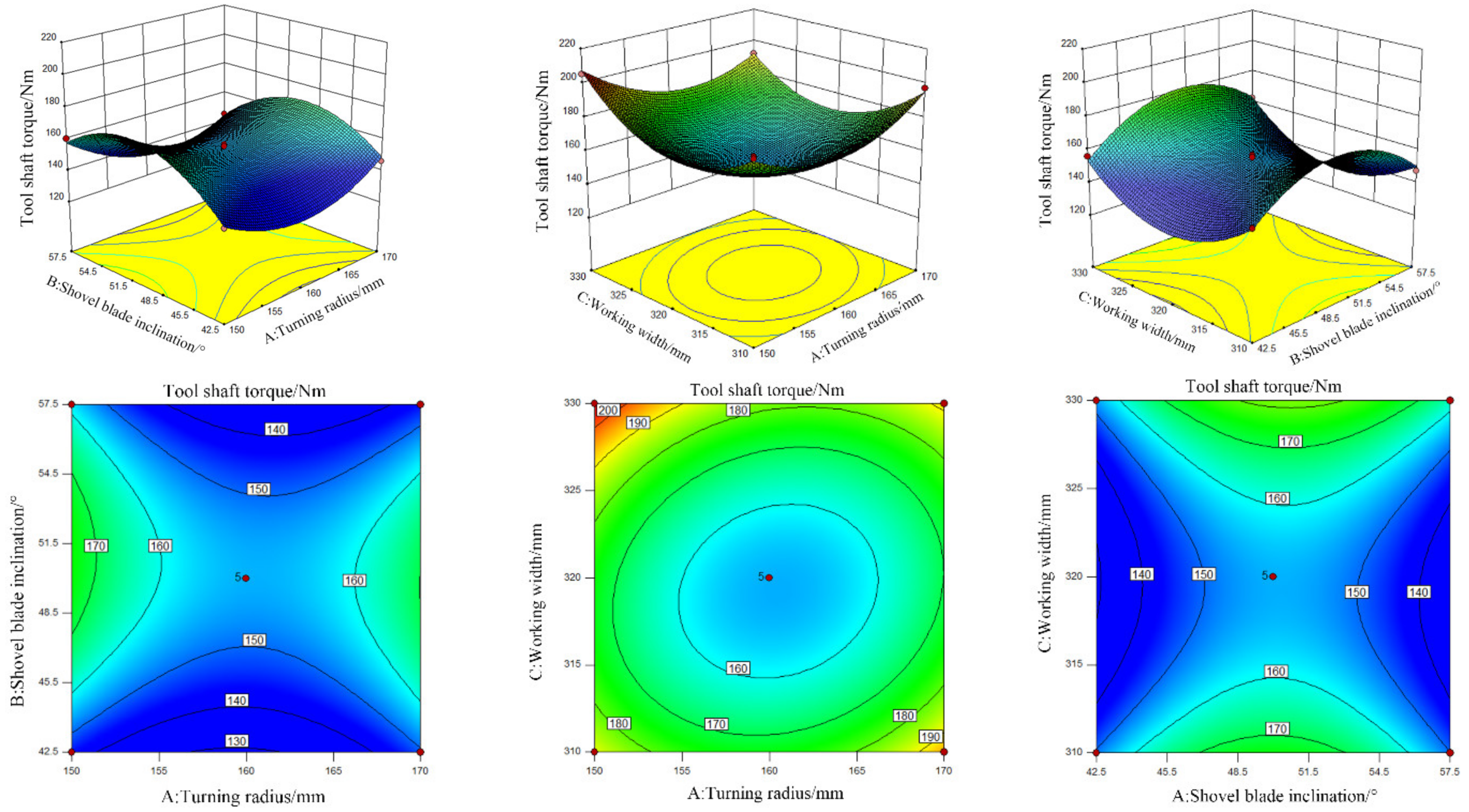
The effect of the test factors radius of gyration R, inclination angle of cutting edge β, and working width L on the torque of the Cyperus esculentus harvesting shaft is shown in Figure 18. In the interval from −1~0, with the gradual increase of the factor level of the radius of gyration R, the torque of the Cyperus esculentus harvesting blade axis gradually decreased between 155.72~173.53 Nm, and the rate of decrease gradually tended to 0. In the interval from 0~1, the tool shaft torque gradually increased, but the growth rate was slow and tended to level off. This is mainly due to the fact that as the radius of gyration R increases, the counter-rotating blade causes the fragmentation of the Cyperus esculentus agglomerates while causing the disturbance of the soil layer around the Cyperus esculentus agglomerates during the harvesting process, resulting in a certain buffering of the tool shaft torque during the harvesting process, and the final change tends to level off [23,25,29]. In the −1~0 interval, with the gradual increase of the inclination angle of cutting edge β factor level, the Cyperus esculentus harvesting tool shaft torque gradually increased between 126.51~155.23 Nm and the increase rate gradually decreased. The overall change trend was consistent with the change in working resistance [13,14,21]. In the interval from −1~0.5, with the gradual increase of the working width L factor level, the Cyperus esculentus harvesting tool shaft torque gradually decreased between 175.45~156.13 Nm, and the changing trend tended to level off in the interval from −0.5~0. In the interval from 0~1, with the increasing working width L, the counter-rotating blade entry width increased during Cyperus esculentus harvesting, leading to the rapid increase of the tool shaft torque. The overall change trend was consistent with the change in working resistance [18,19,24].
Combined with tool shaft torque variance analysis, the test factors radius of gyration R, inclination angle of cutting edge β, and working width L interact with the tool shaft torque, as shown in Figure 19. P (AB) = 0.0159, P (AC) < 0.01 and P (BC) = 0.1124, indicating that (AB) and (AC) have an interactive effect on the test index tool shaft torque, which is consistent with the analysis of Table 7.

3.3. Experimental Optimization and Validation

In order to obtain the optimal combination of the structural parameters of the counter-rotating blade for the experimental factors, the optimal design of the experiment was carried out. Combined with the boundary conditions of the experimental factors, a parametric mathematical model was established. To reduce the working resistance and tool shaft torque, regression analysis was carried out on the working resistance and tool shaft torque of the counter-rotating excavation device, and the following nonlinear programming parameter model was established:
min   Y 1 min   Y 2 150   mm A 1 70   mm 42.5 ° B 47.5 ° 310   mm C 330   mm
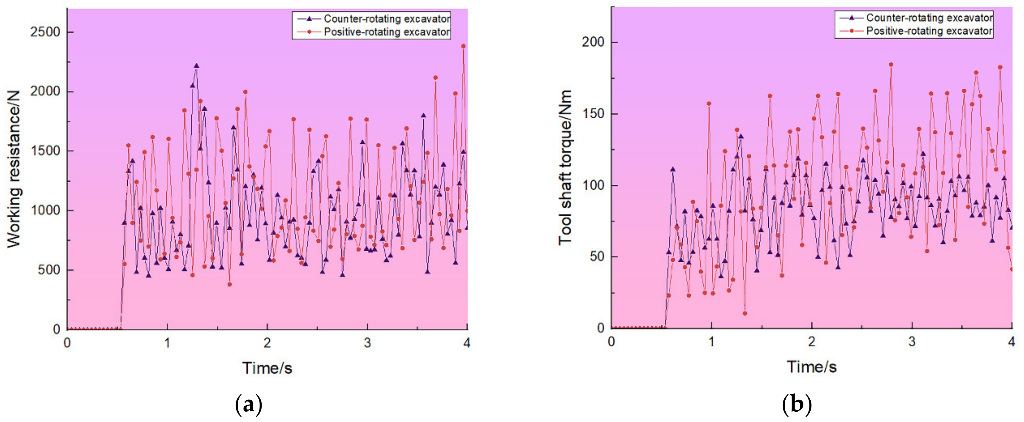
When the radius of gyration 151 mm, inclination angle of cutting edge 42.5° and working width 318 mm is the combination of the optimal structural parameters of the counter-rotating blade. Comparative tests were conducted with the Cyperus esculentus positive-rotating excavation device under optimal structural parameters of the counter-rotating blade, and the test results are shown in Figure 20a,b.
According to the comparative analysis of the working resistance of Cyperus esculentus harvesting in Figure 20a, the average working resistance of the designed counter-rotating excavation device is 836.65 N, the average working resistance of the positive- rotating excavation device is 942.79 N, and the working resistance is reduced by 11.25%. According to the comparative analysis of the torque of the tool shaft of Cyperus esculentus harvesting in Figure 20b, the average torque of the tool shaft of the designed counter-rotating excavation device is 72.21 Nm, and the average torque of the tool shaft of the positive- rotating excavation device is 86.08 Nm, and the torque of the tool shaft is reduced by 16.11%. This shows that the designed counter-rotating excavation device for Cyperus esculentus can achieve the effect of reducing drag.

3.4. Field Trial Results and Analysis

From the test results in Table 9, it can be seen that the highest value of the fruit burial rate of counter-rotating excavation is 1.48%, the lowest value is 1.23%, and the average value is 1.37%; the highest value of the fruit burial rate of positive-rotating excavation is 1.65%, the lowest value is 1.42%, the average value is 1.54%; buried fruit rate decreased by 11.6% year-on-year. From the test results in Table 9, it can be seen that the highest damage rate of counter-rotating excavation is 1.53%, the lowest value is 1.25%, and the average value is 1.38%; the highest damage rate of positive-rotating excavation is 1.53%, the lowest is 1.25%, and the average is 1.47%; damage rate decreased by 6.1% year-on-year.
Combined with the previous analysis of the movement trajectory of the positive-rotating and counter-rotating rotary excavation method, a comparison can be obtained; in the process of oil bean harvesting, counter-rotating excavation can improve the cutting speed of the soil, while cutting the soil at the same time to reduce the cutting thickness of the soil layer, to achieve the orderly harvesting of Cyperus esculentus agglomerates; positive-rotating excavation harvesting soil cutting thickness is large and cutting speed is slow, in the front of the excavation device it is easy to produce soil accumulation phenomenon, resulting in digging resistance and knife shaft torque increase, which is consistent with the test results. The test results show that the designed counter-rotating excavation device further improves the harvesting efficiency of Cyperus esculentus.

4. Discussion

Currently, scholars have conducted intensive research and achieved many results in the design of Cyperus esculentus excavation and have made many achievements. He et al. [2], used Design-Expert Experiment optimization, and regression analysis was carried out to determine the best structural parameters of the rotary tiller as: bending angle 130° and working width 45 mm. Compared with the normal rotary tillage method under the same parameter settings, the working resistance was reduced by 8.5%, The torque of the cutter shaft was reduced by 5.8%, which proves that the anti-rotating excavation has the effect of reducing resistance. He et al. [30] designed a reverse spin-throw type, and the results show that the optimum combination of parameters for the reverse rotary tiller is: phase angle 67°, installation spacing 144 mm, soil breakage rate 94.20%, and buried fruit rate 1.42%. Under the same parameter settings with ordinary rotary tiller combination for field verification test, the results show that buried fruit rate reduced by 13.33% and soil breakage rate increased by 3.15%. In recent research on the Cyperus esculentus excavating device, the main focus has been on the optimisation of the structural parameters of the rotary tillage knife and the structural design. To a certain extent, the harvesting efficiency of Cyperus esculentus has been improved.
This paper focuses on the analysis of the movement trajectory of the positive-rotating and counter-rotating Cyperus esculentus excavation device, establishes a agglomerate model of soil-Cyperus esculentus tuber-Cyperus esculentus root system-mechanism, and conducts discrete element simulation tests on Cyperus esculentus agglomerates under different soil layers. The optimal structural parameters of the anti-rotation excavating device for Cyperus esculentus were determined by discrete element simulation and field harvesting tests. To further test the scientific validity of the test, the field results were compared with other relevant studies [2,30]; the results of the analysis are shown in Table 10. Compared to the optimised-rotary tillage and the normal-rotary excavation, the fruit burial rate of counter-rotating excavation decreased by 21.71% and 33.81%, and the working resistance of counter-rotating excavation decreased by 9.88% and 17.61%. The results show that the design ideas adopted in this study are feasible and enrich the design method of the Cyperus esculentus excavation device, further improving the harvesting efficiency of Cyperus esculentus.

5. Conclusions

(1)
This paper focuses on the movement trajectory of the positive-rotating and counter-rotating Cyperus esculentus excavation device, comparing and analyzing the cutting soil speed, cutting soil thickness, and the height of the raised bottom of the trench under positive-rotating and counter-rotating operation, showing that counter-rotating excavation can improve the harvesting efficiency of Cyperus esculentus.
(2)
According to the Design-Expert test optimization, the optimal structural parameters of the counter-rotating blade are determined: the radius of gyration is 151 mm, the inclination angle of the cutting edge is 42.5°, and the working width is 318 mm. Comparing with the positive-rotating excavation device under the optimal structural parameters of the counter-rotating blade, the results show that the working resistance is reduced by 11.25%, and the torque of the tool shaft is reduced by 16.11%, which proves that the reverse rotation excavation device has the effect of reducing resistance.
(3)
The field comparison test was conducted based on the evaluation indicators of the burial rate and the damage rate. The results showed that the fruit buried rate of the counter-rotating excavation device decreased by 11.6%, and the damage rate decreased by 6.1%, which proves that the counter-rotating excavation device further improves the harvesting efficiency of Cyperus esculentus.

Author Contributions

Conceptualization, Z.Z. and D.W.; methodology, Z.Z.; software, Z.Z.; validation, Z.Z., H.Z. and H.W.; formal analysis, Z.Z. and C.X.; investigation, Z.Z.; resources, Z.Z.; data curation, Y.W., Z.C. and D.L.; writing—original draft preparation, Z.Z.; writing—review and editing, S.S. and J.H.; visualization, Z.Z.; supervision, Z.Z.; project administration, X.H.; funding acquisition, X.H. All authors have read and agreed to the published version of the manuscript. (Design and Testing of Discrete Element-based Counter-rotating Excavation Device for Cyperus esculentus).

Funding

This research was funded by the Autonomous Region Science and Technology Support Project Plan (Grant NO. 2020E02112) and the Major Science and Technology Projects in Henan Province (Grant NO. 211100110100).

Institutional Review Board Statement

Not applicable.

Data Availability Statement

Not applicable.

Conflicts of Interest

The authors declare no conflict of interest.

References

  1. Wang, R.Y.; Wang, X.S.; Xiang, H. An emerging multi-purpose oilseed crop-Cyperus esculentus. Chin. J. Oil Crop Sci. 2019, 44, 1–4. [Google Scholar]
  2. He, X.N.; Zhang, X.J.; Zhao, Z.; Shang, S.Q.; Wang, D.W.; Yang, S. Design and optimisation tests of reverse spin-throwing Cyperus esculentus starting device. Trans. Chin. Soc. Agric. Mach. 2022, 53, 34–43. [Google Scholar]
  3. Zhang, S.A.; Li, P.Z.; Wei, Z.M.; Cheng, Y.; Liu, J.Y.; Yang, Y.M.; Wang, Y.Y.; Mu, Z.S. Cyperus (Cyperus esculentus L.): A Review of Its Compositions, Medical Efficacy, Antibacterial Activity and Allelopathic Potentials. Plants 2022, 11, 1127. [Google Scholar] [CrossRef] [PubMed]
  4. Yang, Z.L. Characteristics and research progress of Cyperus esculentus. North. Hortic. 2017, 17, 192–201. [Google Scholar]
  5. Yang, X.D.; Li, Z.Y. Current situation, potential and countermeasures for the development of China’s Cyperus esculentus industry. Chin. J. Oil Crop Sci. 2022, 7, 1–6. [Google Scholar]
  6. Qiu, Z.F.; Li, Q.L.; Jiang, W.; Zhang, Z.C.; Zhang, H.; Li, N.; Cui, Z.K.; Zhou, J. Current status of research on Cyperus esculentus planting and harvesting machinery and equipment. J. Shanxi Agric. Univ. Nat. Sci. 2022, 42, 96–106. [Google Scholar]
  7. Wang, Z.C.; Li, S.S.; Liang, X.; Xu, L.J.; Zou, X.J. Development status and prospect of Cyperus esculentus industry in China. Sci. Technol. Indus. 2022, 22, 62–67. [Google Scholar]
  8. Guo, T.T.; Wan, C.J.; Huang, F.H.; Wei, C.L.; Hu, Z.H. Research Progress on main nutritional components and physiological functions of Cyperus esculentus. Chin. J. Oil Crop Sci. 2021, 43, 1174–1180. [Google Scholar]
  9. Gao, Y.L. Simulation Optimization and Experimental Study of a Counter-Rotating Straw Returning Machine Based on the Discrete Element Method. Master’s Thesis, Anhui Agricultural University, Anhui, China, 2019. [Google Scholar]
  10. Zhang, J. Simulation Optimization and Experimental Research of Straw Returning Machine Based on Discrete Element Method. Master’s Thesis, Anhui Agricultural University, Anhui, China, 2018. [Google Scholar]
  11. Wang, F.H.; Xiong, H.H.; Lai, Q.H.; Liu, Z.Y.; Chen, K.F.; Lu, C.Y. Research on intelligent design system and evaluation method for potato harvester digging device. Trans. Chin. Soc. Agric. Mach. 2021, 52, 86–97. [Google Scholar]
  12. Yang, Y.W.; Tong, J.; Ma, Y.H.; Jiang, X.H.; Li, J.G. Design and testing of a bionic rotary tillage knife featuring the multi-toe structure of the mole. Trans. Chin. Soc. Agric. Eng. 2019, 35, 37–45. [Google Scholar]
  13. Fu, W.; Chen, H.T. Optimisation of vibratory loosening shovel parameters for radish harvesters. Trans. Chin. Soc. Agric. Eng. 2011, 27, 46–50. [Google Scholar]
  14. Yang, H.; Cao, M.; Wang, B.; Hu, Z.; Xu, H.; Wang, S.; Yu, Z. Design and Test of a Tangential-Axial Flow Picking Device for Peanut Combine Harvesting. Agriculture 2022, 12, 179. [Google Scholar] [CrossRef]
  15. Zhang, S.L.; Wang, X.S.; Zhang, D.C. A Traction Type Cyperus esculentus Harvester. China Patent CN216313995U, 19 April 2022. [Google Scholar]
  16. Habibi, A.J.; Surendra, S. Optimization and evaluation of rotary tiller blades: Computer solution of mathematical relations. Soil Tillage Res. 2009, 106, 1–7. [Google Scholar]
  17. Jian, J.M.; Chen, H.K.; Hou, S.L.; Zhou, M.; Wang, L.; Tian, J.Y.; Bi, T. A Low Loss Spiral Digging and Vertical Sieve Type Screening Cyperus esculentus Harvester. China Patent CN216313995U, 13 July 2021. [Google Scholar]
  18. Fan, Y. Research on Potato Digging Mechanism and Bionic Shovel Design Based on Discrete Element Method. Doctoral Thesis, Shenyang Agricultural University, Shenyang, China, 2020. [Google Scholar]
  19. Yang, R.B.; Fan, Y.B.; Shang, S.Q.; Liu, L.H.; Cui, G.P. 4HBL-2 peanut combine harvester re-harvesting device design and test. Trans. Chin. Soc. Agric. Mach. 2016, 47, 115–120+107. [Google Scholar]
  20. Ding, W.M.; Wang, Y.H.; Peng, S.Z. Reversing rotary tool orthotropic analysis and parameter selection. Trans. Chin. Soc. Agric. Mach. 2004, 4, 40–43. [Google Scholar]
  21. Fang, H.M. Study on the Mechanism of Straw-Soil-Rototiller Interaction Based on the Discrete Element Method. Doctoral Thesis, Nanjing Agricultural University, Nanjing, China, 2016. [Google Scholar]
  22. Lee, K.S.; Park, S.H.; Park, W.Y.; Lee, C.S. Strip tillage characteristics of rotary tiller blades for use in a dryland direct rice seeder. Soil Tillage Res. 2003, 71, 25–32. [Google Scholar] [CrossRef]
  23. Sun, J.Y.; Wang, Y.M.; Ma, Y.H.; Tong, J.; Zhang, Z.J. DEM simulation of bionic subsoilers (tillage depth > 40 cm) with drag reduction and lower soil disturbance characteristics. Adv. Eng. Softw. 2018, 119, 30–37. [Google Scholar] [CrossRef]
  24. Pirchio, M.; Fontanelli, M.; Labanca, F.; Sportelli, M.; Frasconi, C. Energetic Aspects of Turfgrass Mowing: Comparison of Different Rotary Mowing Systems. Agriculture 2019, 9, 178. [Google Scholar] [CrossRef] [Green Version]
  25. Zheng, K.; He, J.; Li, H.W.; Zhao, H.B.; Hu, H.N.; Liu, W.Z. Design and testing of a counter-rotating deep pine combine tiller Trans. Chin. Soc. Agric. Mach. 2017, 48, 61–71. [Google Scholar]
  26. Zhao, J.Z. Simulation and Experimental Research on the Working Resistance of Potato Excavator Based on Discrete Element Method. Master’s Thesis, Shenyang Agricultural University, Shenyang, China, 2017. [Google Scholar]
  27. Zhang, Y.; Liu, J.; Yuan, W.; Zhang, R.; Xi, X. Multiple Leveling for Paddy Field Preparation with Double Axis Rotary Tillage Accelerates Rice Growth and Economic Benefits. Agriculture 2021, 11, 1223. [Google Scholar] [CrossRef]
  28. Ding, W.M.; Wang, Y.H.; Peng, S.Z. Performance analysis of forward and reverse rotary tiller and comparative cutting torque test. Nanjing Agric. Univ. 2001, 1, 113–117. [Google Scholar]
  29. He, X.N.; Zhang, X.J.; Zhao, Z.; Shang, S.Q.; Wang, D.W.; Yuan, X.W. Design and testing of a discrete element method-based Cyperus esculentus resistance reduction excavation device. Trans. Chin. Soc. Agric. Mach. 2021, 52, 124–133. [Google Scholar]
  30. Guo, J.; Ji, C.Y.; Fang, H.M.; Zhang, Q.Y.; Hua, F.L.; Zhang, C. Experimental analysis of soil and straw displacement after forward and reverse rotational tillage. Trans. Chin. Soc. Agric. Mach. 2016, 47, 21–26. [Google Scholar]
  31. Wang, J.W.; Li, X.; Gao, P.X.; Na, M.J.; Wang, Q.; Zhou, W.Q. Design and testing of an efficient drag-reducing loosening shovel for carrot combine harvesters. Trans. Chin. Soc. Agric. Mach. 2020, 06, 93–103. [Google Scholar]
  32. Zhang, J. Research on Energy-Saving Technology of Down-Cut Deep-Rotary-Tillage Rotary Tiller. Doctoral Thesis, Nanjing Institute of Agricultural Mechanization, Ministry of Agriculture and Rural Affairs, Nanjing, China, 2021. [Google Scholar]
  33. Zhao, H.; Huang, Y.; Liu, Z.; Liu, W.; Zheng, Z. Applications of Discrete Element Method in the Research of Agricultural Machinery: A Review. Agriculture 2021, 11, 425. [Google Scholar] [CrossRef]
  34. Zhu, H.; He, X.; Shang, S.; Zhao, Z.; Wang, H.; Tan, Y.; Li, C.; Wang, D. Evaluation of Soil-Cutting and Plant-Crushing Performance of Rotary Blades with Double-Eccentric Circular-Edge Curve for Harvesting Cyperus esculentus. Agriculture 2022, 12, 862. [Google Scholar] [CrossRef]
  35. Han, L.J.; Yuan, W.; Yu, J.J.; Jin, J.J.; Xie, D.S. Simulation and Experiment of Spiral Soil Separation Mechanism of Compound Planter Based on Discrete Element Method (DEM). Agriculture 2022, 12, 511. [Google Scholar] [CrossRef]
  36. Ucgul, M.; Fielke, J.M.; Saunders, C. 3D DEM tillage simulation: Validation of a hysteretic spring (plastic) contact model for a sweep tool operating in a cohesionless soil. Soil Tillage Res. 2014, 144, 220–227. [Google Scholar] [CrossRef]
  37. Zhao, Q.L.; Chen, X.M.; Xu, S.; Meng, X.Y.; Liu, H.B. Design and testing of an air-priming Cyperus esculentus precision planter seed discharger. Acta Agric. Univ. Jilin 2022, 7, 1–9. [Google Scholar]
  38. Magalhães, P.S.G.; Bianchini, A.; Braunbeck, O.A. Simulated and Experimental Analyses of a Toothed Rolling Coulter for Cutting Crop Residues. Biosyst. Eng. 2007, 96, 193–200. [Google Scholar] [CrossRef]
  39. Xu, G.M.; Xie, Y.X.; Matin, M.A.; He, R.Y.; Ding, Q.S. Effect of Straw Length, Stubble Height and Rotary Speed on Residue Incorporation by Rotary Tillage in Intensive Rice–Wheat Rotation System. Agriculture 2022, 12, 222. [Google Scholar] [CrossRef]
  40. Jan, D.P.; Gemmina, D.E.; Daniel, V.F.R.; Adam, B.; Wim, M.C. Calibration of DEM material parameters to simulate stress-strain behavior of unsaturated soils during uniaxial compression. Soil Tillage Res. 2019, 194, 104303–104312. [Google Scholar]
  41. Qi, J.; An, S.; Kan, Z.; Meng, H.; Li, Y.; Zhao, X. Discrete element-based calibration of simulation parameters of Cyperus esculentus L. (tiger nut) planted in sandy soil. J. Food Process. Preserv. 2021, 45, 15631. [Google Scholar] [CrossRef]
  42. Rahman, S.; Chen, Y. Laboratory investigation of cutting forces and soil disturbance resulting from different manure incorporation tools in a loamy sand soil. Soil Tillage Res. 2001, 58, 19–29. [Google Scholar] [CrossRef]
Figure 1. Overall structure of the Cyperus esculentus combine harvester.
Agriculture 12 01608 g001
Figure 2. Structure parameters of counter-rotating excavation device.
Agriculture 12 01608 g002
Figure 3. Trajectory analysis of positive-rotating and counter-rotating rotation. (a) Trajectory analysis of positive-rotating, where vm1 is machine advance speed of positive rotation, m/s; ω1 is tool shaft rotation speed of positive rotation, rad/s; S1 is soil cutting pitch of positive rotation, mm; d1 is positive-rotating movement of the soil with cutting thickness, mm; h1 is positive-rotating harvesting groove bottom bulge height, mm; R1 is motion radius of gyration of positive rotation, mm. (b) Trajectory analysis of counter-rotating, where vm2 is machine advance speed of counter rotation, m/s; ω2 is tool shaft rotation speed of counter rotation, rad/s; S2 is soil cutting pitch of counter rotation, mm; d2 is counter-rotating movement of the soil to the cutting thickness, mm; h2 is counter-rotating harvesting groove bottom bulge height, mm; R2 is motion radius of gyration of counter rotation, mm.
Agriculture 12 01608 g003
Figure 4. Structure of the counter-rotating blade.
Agriculture 12 01608 g004
Figure 5. Schematic diagram of the force of counter-rotating blade, where Fx is the working resistance of the counter-rotating blade in the x direction, N; Fy is the working resistance of the counter-rotating blade in the y direction, N; Fn is the total resistance of the counter-rotating blade, N; ρ is rotary tillage soil cutting-specific resistance; φ is counter-rotating blade rotation angle, °; σ is the angle between Fn and the tangent of trochoidal, °; Δθ is the angle between tangent of circle and tangent of trochoidal, °; R is the motion radius of gyration, mm; and vm is machine advance speed, m/s.
Agriculture 12 01608 g005
Figure 6. Cyperus esculentus planting pattern.
Agriculture 12 01608 g006
Figure 7. Soil discrete element model. (a) Single grain spherical model; (b) three-grain flake model; (c) four-grain block model; (d) four-grain rod model.
Agriculture 12 01608 g007
Figure 8. Discrete element model of Cyperus esculentus tuber. (a) Cyperus esculentus tuber model; (b) discrete element modeling of Cyperus esculentus.
Agriculture 12 01608 g008
Figure 9. Discrete element model of Cyperus esculentus root system. (a) Cyperus esculentus root system model; (b) discrete element modeling of Cyperus esculentus.
Agriculture 12 01608 g009
Figure 10. Soil contact particle model, where O1 and O2 is the center of the circle of the soil model; R1 and R2 is the radius of the soil model; Fn is normal contact force, N; Ft is tangential contact force, N; Mn is normal moment, Nm; and Mt is tangential moment, Nm.
Agriculture 12 01608 g010
Figure 11. Cyperus esculentus agglomerate. (a) The overall model of Cyperus esculentus agglomerate; (b) the vector model of the Cyperus esculentus agglomerate.
Agriculture 12 01608 g011
Figure 12. Discrete element simulation test of Cyperus esculentus agglomerate counter-rotation excavation. (a) 1 s; (b) 2 s; (c) 3 s; (d) 4 s.
Agriculture 12 01608 g012
Figure 13. Field trial conditions measurement. (a) Measurement of planting pattern of Cyperus esculentus; (b) planting depth measurement of Cyperus esculentus.
Agriculture 12 01608 g013
Figure 14. Field trial. (a) The counter-rotating excavation device; (b) the positive-rotating excavation device.
Agriculture 12 01608 g014
Figure 15. Results of single-factor test on evaluation indicators. (A) Results of single-factor test on radius of gyration R. (B) Results of single-factor test on inclination angle of cutting edge β. (C) Results of single-factor test on working width L.
Agriculture 12 01608 g015
Figure 16. The relationship between each test factor and the working resistance.
Agriculture 12 01608 g016
Figure 17. The response surface of each test factor to working resistance.
Agriculture 12 01608 g017
Figure 18. The relationship between each test factor and the tool shaft torque.
Agriculture 12 01608 g018
Figure 19. The response surface of each test factor to tool shaft torque.
Agriculture 12 01608 g019
Figure 20. The response surface of each test factor to tool shaft torque. (a) Results of comparative analysis of working resistance. (b) Results of comparative analysis of tool shaft torque.
Agriculture 12 01608 g020
Table 1. Discrete element contact parameters.
ParametersValues
Working width/(mm)1000
Working depth/(mm)0~200
Dimension (L × W × H)/(mm)1250 × 950 × 800
Matching power/(kW)75~100
Operation efficiency/(km·h−1)1.1~1.5
Table 2. Discrete element contact parameters.
Contact ModelRestitution CoefficientStatic Friction CoefficientRolling Friction Coefficient
Soil–soil0.430.550.15
Soil–excavation device0.210.520.13
Soil–tuber0.130.460.01
Soil–root system0.140.420.01
Root system–root system0.530.620.58
Root system–excavation device0.400.530.01
Root system–tuber0.210.420.10
Tuber–tuber0.360.250.032
Tuber–excavation device0.720.560.16
Table 3. Discrete element contact parameters.
Contact ModelDensity (Kg/m3)Poisson’s RatioModulus of Shear (Pa)
Soil14560.382.5 × 106
Tuber28600.431.56 × 107
Root system10700.560.93 × 105
Table 4. Soil parameter information.
Soil Depth/mmSoil Moisture Content/%Soil Density/g/cm3Soil Firmness/Kpa
0~5010.231.57364
50~15013.651.63517
150~20015.781.75756
Table 5. Test factor codes.
Test FactorSymbolTest Level
−101
Radius of gyration (mm)A150160170
Inclination angle of cutting edge (°)B42.55047.5
Working width (mm)C310320330
Table 6. Results of multi-factor test.
No.Test FactorsEvaluation Indicator
Radius of GyrationInclination Angle of Cutting EdgeWorking WidthWorking Resistance y1/NTool Shaft Torque y2/Nm
1−1−101424.93157.24
21−101515.38160.57
3−1101556.51156.45
41101659.62191.75
5−10−11536.25143.64
610−11677.88151.58
7−1011775.68153.38
81011839.75205.38
90−1−11630.54147.36
1001−11766.16162.58
110−111645.77188.85
120111956.57197.32
130001718.27145.23
140001732.73146.32
150001714.71153.45
160001734.53152.56
170001781.73155.75
Table 7. Working resistance analysis of variance.
SourceSum of SquaresFreedomMean SquareFp-Value
Model2.58 × 105928,609.8317.70<0.01 **
A19,926.27119,926.2712.33<0.01 **
B65,204.19165,204.1940.35<0.01 **
C46,047.02146,047.0228.49<0.01 **
AB40.06140.060.0250.8793
AC1503.8911503.890.930.3668
BC7672.0117672.014.750.0658
A260,457.14160,457.1437.41<0.01 **
B225,261.58125,261.5815.63<0.01 **
C234,732.05134,732.0521.49<0.01 **
Residual11,312.6671616.09--
Lack of Fit8441.7332813.913.920.1100
Pure Error2870.934717.73--
Note: 0.001 < p < 0.01 (highly significant, **).
Table 8. Tool shaft torque analysis of variance.
SourceSum of SquaresFreedomMean SquareFp-Value
Model6182.969687.0084.52<0.01 **
A39.69139.694.880.0628
B39.38139.384.850.0636
C120.511120.5114.83<0.01 **
AB81.18181.189.99<0.01 **
AC122.101122.1015.020.0129 *
BC26.78126.783.290.2819 *
A21348.8311348.83165.95<0.01 **
B22312.2712312.27284.49<0.01 **
C22315.5312315.53284.89<0.01 **
Residual56.8978.13--
Lack of Fit41.71313.903.660.1211
Pure Error15.1943.80--
Note: 0.01 < p < 0.05 (significant, *); 0.001 < p < 0.01 (highly significant, **).
Table 9. Field trial results.
No.Counter-Rotating ExcavationPositive- Rotating Excavation
Fruit Burial rate/%Damage Rate/%Fruit Burial Rate/%Damage Rate/%
11.431.251.551.32
21.231.381.421.48
31.351.321.581.41
41.311.411.491.52
51.521.531.651.61
Average value1.371.381.541.47
Table 10. The results of field trial results discussion.
Type of Excavation DeviceFruit Burial Rate/%Working Resistance/N
Counter-rotating excavation1.37836.65
Optimised-Rotary tillage1.75928.36
Normal-Rotary excavation2.071015.52
Publisher’s Note: MDPI stays neutral with regard to jurisdictional claims in published maps and institutional affiliations.