Abstract
Vehicle lateral stability is evaluated using the static overturning angle. The correct value of this parameter depends on the calculation method. The aim of this study was to compare the latest standard with previously published methodology, to propose two alternative methodologies (Models 1 and 2) and to analyze the influence of various levels of rear wheel ballast weights and overall tire widths on the stability of universal and subcompact tractors. The results showed a significant regression effect of the rear wheel ballast weight on static overturning angle. The influence of the rear wheel ballast weight was higher in the subcompact tractor than in the universal tractor due to a larger distance between the height of the center of gravity and the center of the rear axle. Comparing the latest standard with the previously published methodology, the highest difference values were 13.82% and 7.30%. Both models are based on the previously published methodology and differ from each other in rolling and slope lines. The methodology proposed in Model 2 differed from the standard similarly to the previously published methodology; therefore, it is irrelevant. Model 1 reached differences of only −1.81% and −1.63%, representing a minimal difference from the standard.
1. Introduction
The use of agricultural tractors is recognized as the most hazardous activity for farmers due to the large number of fatalities occurring every year [1]. The largest number of accidents and injuries involving agricultural machines occur on sloping terrain. Safe operation requires a stable state of machines, even during work in the most extreme conditions [2]. Stability improvement for tractors working on slopes will help avoid dangerous accidents relating to tractor overturning, and allows better tractor utilization on uneven areas which are nonideal for mechanization [3]. There are some practical precautions that can be taken to reduce the probability of tractor overturning. Increasing the distance between the right and left wheels of the tractor as much as possible and trying to lower the height of the tractor’s center of gravity by adding ballast weight to the lowermost parts of the tractor, or by filling 75% of the tractor wheels’ space with water, are widely used measures [4]. The maximum values of ballast weight and overall tire width are limited by specific tractor construction and determined by the tractor manufacturer. Along with other parameters, the rolling behavior of tractors is mainly affected by the geometric dimensions, mass, and height of the center of gravity, as presented by [5] in testing of rollover protective structures. Another study has also confirmed the influence of tractor design parameters such as mass and dimensions on rollover behavior [6]. Tire inflation pressure also affects vehicle stability, because redistribution of vehicle weight onto its sides changes the vector direction of the center of gravity due to tire deflection [7]. Recently, an increase in the operational safety of agricultural vehicles has been achieved by implementation of intelligent systems connected to gyroscopic sensors into vehicle control systems [8].
To explain the lateral stability of a vehicle inclined at the static overturning angle, three-dimensional and two-dimensional sketches are shown in Figure 1. For this purpose, a vehicle without a front swiveling axle is considered as a rigid body. This means that the elasticity of the suspension system and tires is not taken into consideration. The vehicle is inclined at a static overturning angle when the roll moment G sinα h is equal to the moment resulting from the vertical component of the vehicle weight G cosα (0.5 o − z):
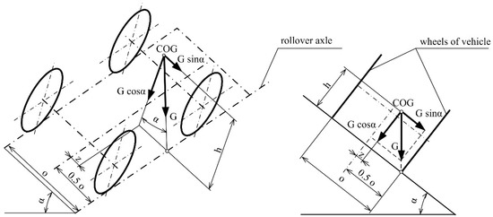
Figure 1.
Forces acting on a vehicle inclined at the static overturning angle: o—overall width on tires; z—lateral position of center of gravity (COG); α—static overturning angle; h—vertical coordinate of COG; G—tractor weight.
In an unstable equilibrium state, a vector of the tractor weight G must cross the ground inside the overall tire width. Therefore, the safety zone is limited by a line connecting the contact of the front and rear wheels on the same side with the ground. The line can be defined as a rollover axle, because the vehicle rotates around this line during a rollover accident.
The influence of the rear wheel ballast weight on tractor stability is shown in Figure 2. The vertical coordinate of COG (center of gravity) is decreased by the ballast weight in the rear wheels (h1 > h2 > h3). It decreases the roll moment, allowing the vehicle to reach a higher static overturning angle (α1 < α2 < α3).
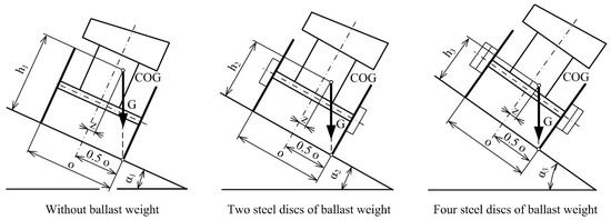
Figure 2.
Influence of the rear wheel ballast weight on tractor stability: o—overall tire width; z—lateral position of COG; α—static overturning angle; h—vertical coordinate of COG.
The overall tire width also improves vehicle lateral stability, as shown in Figure 3. When the overall tire width is increased, the moment resulting from the vertical component of the vehicle weight is decreased, because the moment arm of force is decreased (0.5 o1 < 0.5 o2 < 0.5 o3). The vehicle with a higher overall tire width can reach a higher static overturning angle (α1 < α2 < α3) considering the same vertical coordinate of COG (h).
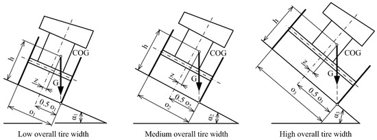
Figure 3.
Influence of the overall tire width on tractor stability: o—overall tire width; z—lateral position of COG; α—static overturning angle; h—vertical coordinate of COG.
Bietresato and Mazzetoo [9] stated that real situations must be necessarily simplified and standardized to be experimentally investigated but, on the other hand, the variety of situations connected with agricultural machine operation does not find an adequate match with test situations proposed by standards. For example, in light of the research presented by [10], it would be advisable to modify the application of the standards for agricultural wheeled tractors in the point referring to the tractor minimum trackwidth. Agricultural tractors are characterized by high rates of standardization and feature a range of additional attachments allowing the wider use of each tractor and greatly facilitate its operation [11]. The need for tractors and agricultural machines to be tested in terms of their suitability for agricultural use will grow continuously because these machines directly affect agricultural production [12,13]. The largest developer of standards is the International Organization for Standardization (ISO). Its principal activity is development of technical and economic standards covering a wide variety of items. Standards are approved by international experts with expertise in their field of professional interest. International standards are accepted worldwide. The standard [14] was developed to evaluate the tractor lateral stability. Grečenko [15] developed a previously published method based on other principles than [14], presenting the fundamental results of research aimed at the static lateral stability of tractors.
The evaluation of vehicle lateral stability is based on static overturning angle calculated from tractor dimensions and the position of the center of gravity. Calculation methodology describes forces acting on a tractor when it rolls over. Mathematical models and theoretical equations are important for analysis of static lateral stability [16,17,18,19]. The main novelty of the article is in the comparison between the standard [14] and the previously published methodology according to [15]. This comparison has not yet been published in scientific literature. The article also presents the proposal of two models for calculation of static overturning angle. These models are based on the methodology according to [15]. The purpose of the model proposal was to improve the methodology according to [15], which is simpler than the standard. Precision improvement of the methodology according to [15] should be proved by new models. Precision improvement was evaluated according to a reduced difference with the standard.
The aim of this study was: (a) the analysis of influence of rear wheel ballast weight and overall tire width on the lateral stability of the subcompact and universal tractor; (b) the comparison of calculation methodologies according to [14,15]; and (c) the proposal of two alternative calculation models based on [15] with rolling and slope line modified according to [14].
2. Materials and Methods
2.1. Characteristics of Experimental Tractors
The experiments were performed using the subcompact tractor MT8-070 Mini (Agrozet a. s., Prostejov, Czech Republic) [20,21] and universal tractor Deutz-Fahr 5100G (SDF S.p.A., Treviglio, Italy). The subcompact tractor was equipped with the tires TS-02, 6.5/75-14 (Mitas a. s., Prague, Czech Republic) on the rear axle and NB 44, 4.00-8 (Barum a. s., Otrokovice, Czech Republic) on the front axle. The rear axle of the universal tractor was equipped with the tires Agri Max 420/85 R34 (BKT, Tirana, Albania) and the front axle with Agri Max 380/85 24 (BKT, Tirana, Albania). The basic technical specifications of the experimental tractors are listed in Table 1.

Table 1.
Specifications of the experimental tractors.
As mentioned in Section 1, Introduction, different tractor design parameters affect rollover behavior, such as mass and dimensions [6]. Therefore, tractors with different characteristics were chosen to provide the comparison of calculation methods. Tractor stability is also affected by wheel dimensions and tire type. The tractors were equipped with standard wheels and tires.
The weight of the subcompact tractor is relatively low in relation to the weight of a tractor driver. Depending on individual human body physiology, the weight of the tractor driver can be up to a third of the tractor weight. To simulate the tractor with driver, the driver seat was loaded with the ballast weight of 75 kg, corresponding with an average human body weight. Jandačka [22] presented that the COG of a human body lies in the area of the 3rd to 4th sacral vertebra. The ballast weight of three sandbags (the weight of one sandbag is 25 kg) equals 75 kg. They were fixed to the tractor driver seat by a tension belt ratchet lashing strap [23] (Figure 4a). The height of three sandbags placed on each other is 45 cm. Then, we consider the COG in the same position as in the human body. On the other hand, the weight of the universal tractor is multiple times higher than the driver weight; therefore, there is no need for simulation of the human body on the tractor seat.
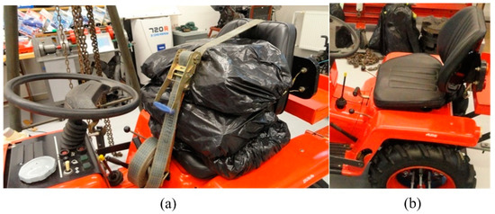
Figure 4.
Simulation of tractor driver: (a) Three sandbags on the driver seat; (b) Empty seat.
The calculation methods for static overturning angle were compared at three overall tire widths (low, medium, and high), as listed in Table 1. Experiments were performed with the tractors equipped with two levels of rear wheel ballast weights and with no ballast weight. The subcompact tractor allows the setting of 30.5 kg or 61 kg of rear ballast weight considering a single steel disc weight of 15.25 kg. The universal tractor was loaded with 180 kg using two single adapters for connections of steel discs. The second load level of 300 kg was achieved using the adapters with two steel discs. The weight of the single adapter was 90 kg, and the weight of the single steel disc was 60 kg.
2.2. Centre of Gravity Coordinates
The coordinates of COG were determined according to [14] (Figure 5). Weight distribution on the rear and front axle and on the right and left tractor side was determined by scales (wheel weighting pads) placed under the tractor wheels. Two weighting pads were used for measurement of weight on two tractor wheels. During weight measurements, wood pads were placed under another two wheels to place the tractor to level position. Wood pads have the same height as weighing pads. The tractors were placed on the level flat floor. To determine the vertical coordinate of COG, the front axle of the subcompact tractor was lifted by a portal crane. The front axle of the universal tractor was lifted using a forklift. The tractor brakes were released, and the transmission was in neutral when the front axle (swiveling axle) was lifted to allow a free rotation of the rear wheels on the scales. The level of fuel in the tank must be considered in terms of stability [24]. The liquid moves in the fuel tank and changes the location of the tractor´s COG. To eliminate the measurement error due to liquid shift, the fuel tank was full of fuel (recommendation of [14]).
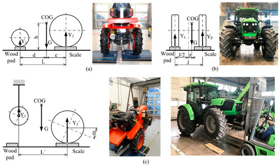
Figure 5.
Experimental determination of COG coordinates: (a) Longitudinal coordinates of COG and rear axle weighting; (b) Calculation of lateral position of COG and left side weighting; (c) Lifted front axle: L—wheelbase; c, d—longitudinal coordinates of COG; h—vertical coordinate of COG; J—tread width; z—lateral position of COG; G—tractor weight; Y1, Y2, YP, YL,—ground reactions; ω—lifting angle; L′—vertical projection of wheelbase; Y1′, Y2′—reaction when the tractor is in raised position.
The wheel weighting pads WWSE 10 T with an indicator (Dini Argeo s. r. l., Spezzano di Fiorano, Italy) were used to weight the experimental tractors. The weighting capacity of 10,000 kg and the resolution of 0.5 kg were used to weight the universal tractor. The weight of the subcompact tractor is significantly lower than the weighting capacity of weighting pads. The weighting system was calibrated by an accredited company, Brutto s. r. o. (Slovak Republic), to the rated capacity of 400 kg with a measuring error of 0.125% and resolution of 0.5 kg. A measuring tape with a measuring range of 2 m, accuracy class 2, and resolution of 1 mm was used for distance measurements. A digital protractor, Genborx 810–100 (Changzhou Skyvictor Ltd., Changzhou, China), with measuring range 4 × 90°, display resolution 0.1°, and accuracy error 0.01°, was used for measurement of tractor inclination angle when the front axle was lifted. All measurements were repeated three times, with calculating the mean value. The effect of rear wheel ballast weights and overall tire widths on static overturning angle was evaluated on the basis of regression analysis using Microsoft Excel (Office 365, version 2107, Microsoft, Redmond, WA, USA).
2.3. Methodology According to ISO 16231-2
The standard [14] presents a method for calculation of the static overturning angle of a tractor with one swiveling axle without a swiveling angle limiting device and the pivot point of swiveling axle in line with the center line of the tractor, as shown in Figure 6. The standard defines the rolling line of the tires on the fixed axle (when rolling laterally) at 75% of tire width. Abscissa AA′ is the base line of the stability triangle and is calculated according to the following formula.
where AA′—base line of the stability triangle, m; o—overall tire width of the fixed axle, m; p—tire width on the fixed axle, m.
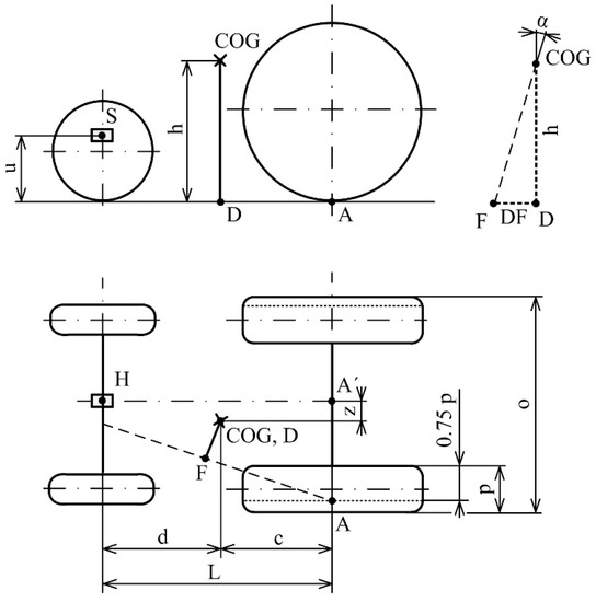
Figure 6.
Determination of tractor lateral stability according to [14]: o—overall tire width of the fixed axle; p—tire width on the fixed axle; u—height of the swelling axle pivot point; L—wheelbase; c, d—longitudinal coordinates of COG; h—vertical coordinate of COG; z—lateral position of COG; α—static overturning angle; AA′—base line of the stability triangle; DF—slope line; A, A′, B, C, D, F, H, M, S—specific points needed for determination of abscissae.
Considering the calculation method according to [14], static overturning angle is calculated using the slope line DF and vertical coordinate of COG h.
where α—static overturning angle, °; DF—length of slope line, m; h–vertical coordinate of COG, m.
2.4. Methodology According to Grečenko
The methodology based on a principle other than the standard [14] was previously published by [15]. In the top view, the stability triangle is formed by the lines AB, BC, and AC using calculation according to [14], as shown in Figure 6. Grečenko [15] presented the stability triangle formed by the lines AH, HC, and AC, as shown in Figure 7. The calculation method of static overturning angle α based on this stability triangle uses the line NK parallel with the tractor rear axle and shortened distance of vertical coordinate of COG. This methodology uses 50% of the tire width in contrast to 75% used in [14]. Considering the same technical conditions and parameters of the tractors as in the methodology according to the standard [14], the base line of stability triangle AA′ is calculated according to Equation (2) using 0.5p instead of 0.75p. Using the two triangles HAA′ and HNO, the distance NK is calculated as follows:
where NK—lateral distance between the vertical projection of COG and the line AH, m; z—lateral position of COG, m; d—horizontal coordinate of COG, m; AA′—base line of the stability triangle, m; L—wheelbase, m.
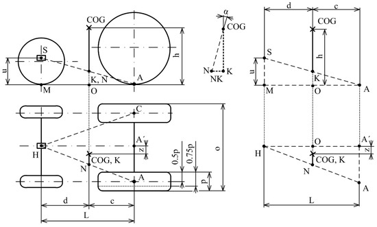
Figure 7.
Calculation of static overturning angle according to [25]: o—overall tire width of the fixed axle; p—tire width on the fixed axle; u—the height of the swelling axle pivot point; L—wheelbase; c, d—longitudinal coordinates of COG; h—vertical coordinate of COG; z—lateral position of COG; α—static overturning angle; AA´—base line of the stability triangle; NK—lateral distance between the vertical projection of COG and line AH; A, A′, B, C, D, F, H, M, S—specific points needed for determination of abscissae.
The methodology uses a shortened distance of the vertical coordinate of COG, as shown in the front view of the tractor sketch (Figure 7) [25]. The height of the COG is shortened by the distance OK, calculated as follows:
where OK—distance between the vertical projection of COG and line SA, m; u—height of the swelling axle pivot point, m; c—horizontal coordinate of COG, m; L—wheelbase, m.
The distance NK is calculated according to Equation (4) and the distance OK according to Equation (5) to determine the static overturning angle according to [15], as follows:
where OK—distance between the vertical projection of COG and line SA, m; NK—lateral distance between the vertical projection of COG and line AH, m; h— vertical coordinate of COG, m; α— static overturning angle, °.
2.5. Design of Alternative Calculation Models
The design of alternative models was based on the methodology according to [15]. An advantage of this calculation methodology is in a simple procedure. A few calculation steps allow getting results in a short time. A change of rolling and slope line for alternative methodologies was proposed according to the research presented in [14]. The blue color marks Model 1, as shown in Figure 8. A 50% of the rolling line of the tires on the fixed axle was replaced by 75%. The calculation methodology for Model 1 follows the steps according to the equations presented by [15]. The red color together with the blue color marks Model 2. The slope line FK is perpendicular to the line HA. The angle θ expresses the slope of the distance FK and can be calculated as follows:
where AA′—base line of the stability triangle, m; L—wheelbase, m.
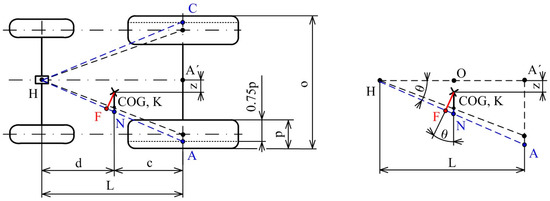
Figure 8.
Scheme for Models 1 and 2 based on the modification of [15]: L—wheelbase; c, d—longitudinal coordinates of COG; z—lateral position of COG; AA′—base line of the stability triangle; NK—slope line for Model 1; FK—slope line for Model 2.
The distance NK is calculated according to Equations (2) and (4). The slope line FK is calculated as follows:
where NKl—ateral distance between the vertical projection of COG and side AH, m; θ—slope of distance FK, m.
The distance OK is calculated according to Equation (5) to get the static overturning angle for Model 2, as follows:
where OK—distance between the vertical projection of COG and line SA, m; FK—slope line, m; h—vertical coordinate of COG, m; α—static overturning angle, °.
2.6. Methodology of Data Reliability
The abscissa AA′ is the base line of the stability triangle. Static overturning angle α is calculated using the slope line DF and vertical coordinate of COG h in the methodology according to the standard [14]. Static overturning angle α according to [15] is calculated using OK (a distance between the vertical projection of COG and line SA), FK (slope line) and h (the vertical coordinate of COG). The accuracy of calculation methods is given by the law of propagation of uncertainty. To calculate the propagation error, the variance formula is presented by [26]:
where s—standard deviation of function f; sx—standard deviation of x; sy—standard deviation of y, etc.
The uncertainty of angle α calculated according to the standard [14] (Equation (3)) is given as follows:
The uncertainty of angle α calculated according to [15] (Equation (6)) is given as follows:
The uncertainty of angle α was calculated for the subcompact and universal tractors without ballast weight and low overall tire width. These are the basic tractor parameters. To calculate the uncertainty of angle α, an accuracy deviation of the vertical coordinate of COG (h) was calculated, as stated in the standard [14]. Therefore, a deviation of 2.5% was calculated for the subcompact tractor and 2.3% for the universal tractor.
3. Results and Discussion
3.1. Evaluation of Tractor Stability Parameters
The coordinates of COG and static overturning angles were calculated according to [14], as listed in Table 2. The influence of overall tire width and rear wheel ballast weight on tractor lateral stability is shown in Figure 9. The regression analysis was used to evaluate the relationship between rear wheel ballast weight and static overturning angle at various overall tire widths. Rear wheel ballast weight was an independent variable. Based on the p-value lower than 0.05, statistically significant relationships were determined, considering the 95% confidence interval. The regression coefficients R2 of linear regressions (higher than 0.99) demonstrate the statistically significant effect of rear wheel ballast weight on static overturning angle.
Table 2.
Data calculated according to [14].
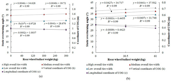
Figure 9.
Static overturning angle calculated according to [14] and coordinates of COG: (a) Universal tractor; (b) Subcompact tractor.
A higher ballast weight in rear wheels increases the static overturning angle due to a decrease in the vertical coordinate of COG (Table 2). Demšar et al. [27] concluded that the distance between the center of gravity from the ground has the greatest effect on static stability. By lowering the center of gravity, longitudinal as well as lateral static stability improve. The limiting factor is clearance height under the tractor. The slope of linear functions reached higher values in the subcompact tractor (0.0407, 0.0427, and 0.0441) than in the universal tractor (0.0041, 0.0046, and 0.0049). It showed a higher influence of rear wheel ballast weights on static lateral stability in the subcompact tractor in comparison with the universal tractor. The subcompact tractor has a higher distance between the center of the rear axle and the center of gravity than the universal tractor. This distance affects the influence of wheel ballast weights on tractor stability. The improvement of the static overturning angle using rear wheel ballast weight is possible only if the rear wheel radius is lower than the vertical coordinate of COG. Otherwise, rear wheel ballast weight worsens the tractor lateral stability. Franceschetti et al. [28] analyzed the effect of tractor protective structures weight on the position of COG. A significant relationship between protective structure weight and tractor stability was demonstrated based on the regression analysis. Ahmadi [4] presented similar results in the study aimed at the influence of tractor weight on lateral stability. Ayers et al. [29] also confirmed that ballast weight can substantially decrease lateral and longitudinal stability angles. Our paper also shows the improvement of tractor stability due to rear wheel ballast weights. The linear dependence (Figure 9) of the vertical coordinate of COG on rear wheel ballast weight allows the prediction of the static overturning angle of the tractor with various rear wheel ballast weights.
Overall tire width is a significant parameter influencing tractor lateral stability, because it affects the base line of stability triangle AA′. The lateral stability of tractors with low, medium, and high overall tire width is shown in Figure 9. The parallel lines of linear models demonstrate the effect of overall tire width on static overturning angle and the static lateral stability of tractors. The result showed that a higher increase in static overturning angle was observed in the universal tractor, because it allowed higher overall tire width in comparison with the subcompact tractor. Gravalos et al. [30] researched the influence of rear track width on the stability of vehicles working on side sloping terrains. The authors improved the static overturning angle by extended overall tire width, which is a very important parameter improving tractor lateral stability.
The highest tractor stability expressed by static overturning angle was reached by a combination of the highest rear wheel ballast weight and high overall tire width.
3.2. Comparison of Calculation Methods
Emam et al. [31], Martin and Pambrun [32], and Gibson et al. [33] presented the stability triangle of various vehicles formed by the lines AH, HC, and AC (Figure 7). This method uses the same principle of lateral stability calculation as [15]. Comparing the stability triangles AB, BC, AC (Figure 6) and AH, HC, AC (Figure 7), the line NK is parallel to the rear axle axis in the methodology according to [15]. It is not possible to calculate the static overturning angle from the full length of the vertical coordinate of COG, but with a distance shortened according to Figure 7. In the case of [14], the slope line DF is perpendicular to the line AH and this method uses the full length of the vertical coordinate of COG. Based on a comparison of both calculation methodologies, it can be concluded that the methodology according to [15] is simpler than [14].
The design parameters of Models 1 and 2 for the calculation of the static overturning angle are listed in Table 3, presenting the parameters for the tractors with three levels of rear wheel ballast weights and overall tire widths. The design parameters are AA′—the base line of the stability triangle; NK—slope line for Model 1; OK—distance between the vertical projection of COG and line connecting a pin of the front axle and the point of contact between the rear wheel and the ground; FK—slope line for Model 2; and θ—the slope of distance FK.
Table 3.
Design features of proposed calculation models.
The standard deviation of the parameters DF (sDF) and h (sh) for the subcompact tractor according to Equations (3) and (11) (methodology according to the standard [14]) was ±0.007 m and ±0.011 m, respectively. The standard deviation of the parameters DF (sDF) and h (sh) for the universal tractor was ±0.012 m and ±0.022 m, respectively. The uncertainty of angle α for the subcompact tractor was 0.016 rad (0.91° or 2.8%) and for the universal tractor 0.013 rad (0.74° or 2.6%).
The standard deviation of the parameters h (sh), NK (sNK), and OK (sOK) for the subcompact tractor according to Equations (6) and (12) (methodology according to [15]) was ±0.011 m, ±0.005 m, and ±0.002 m, respectively. The standard deviation of these parameters for the universal tractor was ±0.022 m, ±0.008 m, and ±0.006 m, respectively. The uncertainty of angle α for the subcompact tractor was 0.018 rad (1.00° or 3.15%) and for the universal tractor 0.013 rad (0.75° or 2.99%). The uncertainty of angle α calculated according to Models 1 and 2 can be considered the same as according to [15], because Models 1 and 2 are based on this previously published methodology. In this case, the small difference can be ignored.
The data calculated according to the previously published methodology [15] for Model 1 and Model 2 are listed in Table 4 for the subcompact and universal tractors. The comparison between the static overturning angle calculated according to [14,15] is shown in Figure 10, Figure 11 and Figure 12. The regression analysis showed regression coefficients R2 higher than 0.99 and p-values lower than 0.05 in the case of all overall tire widths. The static overturning angle calculated according to [15] reached lower values than according to [14]. The constants of the linear regression models differ between [14,15]. Slopes are lower in the case of [15].
Table 4.
Data calculated according to [15], Model 1, and Model 2.
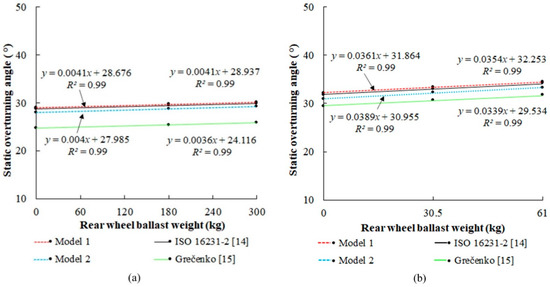
Figure 10.
Comparison of [14,15], Model 1, and Model 2 at low overall tire width: (a) Universal tractor; (b) Subcompact tractor.
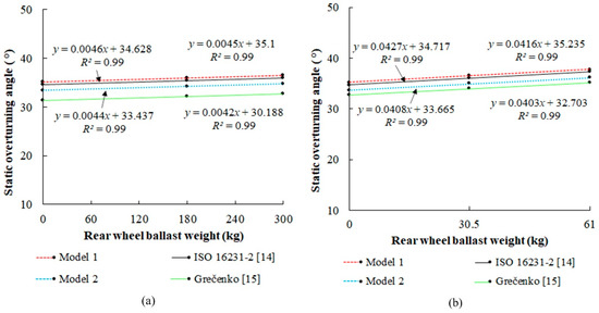
Figure 11.
Comparison of [14,15], Model 1, and Model 2 at medium overall tire width: (a) Universal tractor; (b) Subcompact tractor.
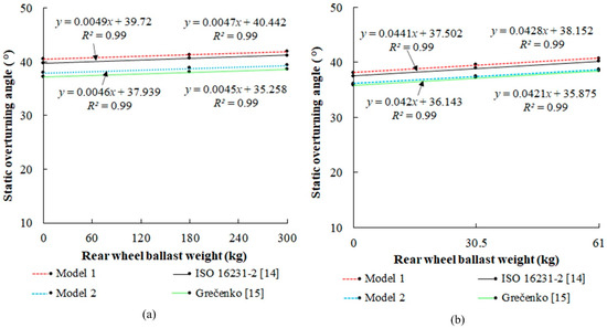
Figure 12.
Comparison of [14,15], Model 1, and Model 2 at high overall tire width: (a) Universal tractor; (b) Subcompact tractor.
The constants of the linear functions of Model 1 and Model 2 are higher than in [15]. Comparing the calculation method according to [14] with Model 1 and Model 2, the difference between constants was reduced. The slopes of the linear functions of Model 1 and Model 2 only minimally differ from [14]. For practical applications, the relationship between the static overturning angle and rear wheel ballast weight can be considered the same in the case of [14], Model 1, and Model 2. All these methods use 75% of tire width (0.75p).
The differences between the static overturning angle calculated according to [14] and [15] are listed in Table 5 and shown in Figure 13. The methodology according to [15] uses the rolling line of the tires on the fixed axle at 0.5p. The highest differences between both methodologies were observed in the subcompact tractor (7.30%, 7.28%, and 7.24%) and universal tractor (13.82%, 13.75%, and 13.71%) with low overall tire width. As overall tire width increased, the difference was reduced. Differences were reduced by about a half in the case of both tractors with the highest overall tire width. Higher differences were observed in the universal tractor than the subcompact tractor. The reason is a lower tire width of the subcompact tractor than the universal tractor. Tire width essentially affects the base line (AA′) of the stability triangle. Differences mean the error of the static overturning angle calculation. Differences are caused by a lower distance between the vertical projection of COG and hypotenuse of the stability triangle according to [15] in comparison with [14]. Increasing the overall tire width, the distance increases more in the case of [15] than [14] due to the difference in the hypotenuse of stability triangles; therefore, the difference between these methodologies decreases. The influence of rear wheel ballast weight on the difference between both methodologies was lower than 0.8% at all overall tire widths and can be considered negligible. The absolute values of static overturning angles calculated according to [15] are lower than the standard in both tractors. The relatively high difference improves the safety of tractor operation but essentially limits the utilization of tractors under real operation conditions.
Table 5.
Percentage difference (%) between [15], Model 1, Model 2, and [14].
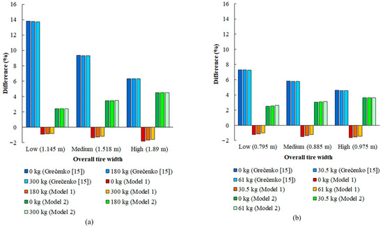
Figure 13.
Comparison of [14] with [15], Model 1, and Model 2: (a) Universal tractor; (b) Subcompact tractor.
Comparing [14] with Model 2, differences decreased in both tractors. The highest differences were observed in the universal tractor (4.48%, 4.49%, and 4.50%) and subcompact tractor (3.63%, 3.62%, and 3.61%) with high overall tire width. Model 1 showed the highest differences in the universal tractor (−1.81%, −1.68%, and −1.60%) and subcompact tractor (1.63%, 1.54%, and 1.42%) at high overall tire width. The minus sign means higher values of static overturning angles calculated according to [15] than [14]. The results mentioned above showed that the difference was decreased in Model 2 and Model 1. In the case of Model 1, the difference is relatively small (<1.81%) and not dangerous for practical conditions considering the safety factor standardly used to ensure tractor operation under safe conditions. In practical conditions, the calculated value of static overturning angle is multiplied by the safety factor. The safety factor is the number which decreases the calculated static overturning angle to eliminate calculation errors caused, for example, by different tire deformations and other undesirable effects.
In contrast to the comparison of [15] with [14], the effect of rear wheel ballast weight on the difference between the standard and both models reached the highest value (17.8%) in Model 1 in the subcompact tractor at low overall tire width. When the difference between the standard and models increased, the effect of rear wheel ballast weight on the difference decreased. Considering the highest differences in Model 2 in the universal tractor at high overall tire width, the effect of rear wheel ballast weight on the difference reached values lower than 0.4%. The effect of rear wheel ballast weight on the difference between the standard and other calculation methods presented in this study is caused by the change of the vertical coordinate of COG c (Table 2 and Figure 9) due to the increase in rear axle weight. Model 2 was evaluated as not suitable for practical application, because it differs from the standard similarly to [15] at high overall tire width, and the methodology is not as simple as in Model 1.
The simplicity of all calculation methods can be explained by the number of calculation steps needed for calculation of static overturning angle. We consider the calculation procedure starting with the calculation of the base line of stability triangle AA′ and ending with the calculation of the static overturning angle α. The number of calculation steps of 12, 4, 4, and 6 is needed for the methodology according to [14,15], Model 1, and Model 2. Therefore, computation is simpler in comparison with the standard [14] in a ratio of 1 to 3 in the case of [15] and Model 1, and in a ratio of 1 to 2 in the case of Model 2.
4. Conclusions
The static lateral stability of the subcompact and universal tractor was analyzed. The results showed that the increase in rear wheel ballast weight and overall tire width improved the static lateral stability of both tractors. It was caused by the decrease in the vertical coordinate of COG when ballast weights were placed in the rear wheels and by the increase in the base line of the stability triangle when overall tire width was extended. The linear models of relationship between the static overturning angle and rear wheel ballast weight allows the prediction of tractor lateral stability at various load levels. Similarly, models can be created to predict the effect of various overall tire widths on tractor lateral stability. The constants of the linear functions showed that the effect of rear wheel ballast weight on tractor stability depends on the distance between the COG and rear wheel center. A greater effect of rear wheel ballast weight on stability was reached when the distance was higher.
The results of this study presented that static overturning angles calculated according to the standard are lower than the previously published methodology. The highest differences were observed at low overall tire width. The increase in overall tire width reduced the differences between these methods due to different construction of stability triangles. Only minimal (negligible) effect of rear wheel ballast weight on the difference between the methods was observed in contrast to the effect of overall tire width, mentioned above. The differences mean higher safety of tractor operation but limit the tractor utilization potential in practice.
Two calculation models (Model 1 and Model 2) were proposed. Model 1 is simpler than Model 2, because it uses fewer steps of calculation methodology. The practical application of Model 2 is irrelevant, because it differs more from the standard than the simpler Model 1, mainly at high overall tire width. Besides the effect of overall tire width on the difference between the models and the standard, the effect of rear wheel ballast weight was also observed in Model 1. The results showed that the effect of rear wheel ballast weight increased when the difference between the standard and other calculation methods decreased. The absolute values of static overturning angles calculated according to Model 1 were higher than the standard. On the other hand, the differences were small; therefore, they can be eliminated by safety factor which is always used to ensure safe tractor operation. Replacing 50% of the rolling line of the tires by 75% in the previously published methodology, Model 1 offers a simple calculation procedure useful for fast determination of tractor lateral stability with certain minimal error depending on dimensions and load distribution of concrete tractor.
Author Contributions
Conceptualization, R.A. and R.M.; data curation, E.M.; formal analysis, Z.T. and K.K.; funding acquisition, R.M.; investigation, R.M. and R.A.; methodology, R.M. and R.A.; project administration, K.K.; software, E.M.; supervision, Z.T.; visualization, E.M.; writing—original draft, R.M.; writing—review and editing, K.K. and Ľ.K.; validation, Ľ.K. All authors have read and agreed to the published version of the manuscript.
Funding
This research received funding from the project VEGA 1/0724/19 mentioned in Acknowledgements.
Institutional Review Board Statement
Not applicable.
Informed Consent Statement
Not applicable.
Data Availability Statement
Not applicable.
Acknowledgments
VEGA 1/0724/19 “Research, Design and Application of Special Driving Wheels for Drawbar Properties Improvement and Elimination of Soil Damage under Operation of Cars and Tractors”.
Conflicts of Interest
The authors declare no conflict of interest.
References
- Fargnoli, M.; Lombardi, M. Safety vision of agricultural tractors: An engineering perspective based on recent studies (2009–2019). Safety 2020, 6, 1. [Google Scholar] [CrossRef]
- Váliková, V.; Rédl, J.; Antl, J. Analysis of accidents rate of agricultural off-road vehicles. J. Cent. Eur. Agric. 2014, 14, 1303–1316. [Google Scholar] [CrossRef][Green Version]
- Bietresato, M.; Mazzetto, F. Definition of the layout for a new facility to test the static and dynamic stability of agricultural vehicles operating on sloping grounds. Appl. Sci. 2019, 9, 4135. [Google Scholar] [CrossRef]
- Ahmadi, I. Development of a tractor dynamic stability index calculator utilizing some tractor specifications. Turk. J. Agric. For. 2013, 37, 203–211. [Google Scholar]
- Síllelí, H. Research on applying an anchor mechanism to orchard and vineyard tractors produced in Turkey. Turk. J. Agric. For. 2007, 31, 389–398. [Google Scholar]
- Franceschetti, B.; Lenain, R.; Rondelli, V. Comparison between a rollover tractor dynamic model and actual lateral tests. Biosyst. Eng. 2014, 127, 79–91. [Google Scholar] [CrossRef]
- Gorshkov, Y.G.; Starunova, I.N.; Kalugin, A.A.; Troyanovskaya, I.P. Investigation of the slope angle influence on the loading imbalance of the wheeled vehicle sides and the change in the center of gravity vector direction. J. Phys. Conf. Ser. 2019, 1177, 012005. [Google Scholar] [CrossRef]
- Rédl, J.; Váliková, V.; Antl, J. Design of active stability control system of agricultural off-road vehicles. Res. Agric. Eng. 2014, 60, 77–84. [Google Scholar] [CrossRef]
- Bietresato, M.; Mazzetto, F. Proposal of an advanced facility to perform static and dynamic tests of stability on agricultural machines. Chem. Eng. Trans. 2017, 58, 151–156. [Google Scholar]
- Molari, G.; Rondelli, V. On the definition of narrow-track wheeled agricultural tractors. Biosyst. Eng. 2004, 88, 75–80. [Google Scholar] [CrossRef]
- Kosiba, J.; Varga, F.; Mojžiš, M.; Bureš, Ľ. The load characteristics of tractor Fendt 926 Vario for simulation on test device. Acta Fac. Tech. 2012, 17, 63–72. [Google Scholar]
- Hujo, Ľ.; Tkáč, Z.; Jablonický, J.; Uhrinová, D.; Halenár, M. The action of force measurement for the three-point hitch of a tractor. Agron. Res. 2017, 15, 162–169. [Google Scholar]
- Hujo, Ľ.; Kosiba, J.; Jablonický, J.; Drabant, Š. Theoretical design of a laboratory test device for the testing of tractor hydraulics. In Technics in Agrissector Technologies; Slovak University of Agriculture in Nitra: Nitra, Slovakia, 2012; pp. 68–73. (In Slovak) [Google Scholar]
- ISO 16231-2. Self-Propelled Agricultural Machinery—Assessment of Stability—Part. 2: Determination of Static Stability and Test Procedures; International Organization for Standardization: Geneva, Switzerland, 2015. [Google Scholar]
- Grečenko, A. Wheel and Caterpillar Tractors; SZN Praha: Praha, Czech Republic, 1963; p. 402. (In Czech) [Google Scholar]
- Choi, K.; Kim, S.; Hong, S. Analysis of static stability by modified mathematical model for asymmetric tractor-harvester system: Changes in lateral overturning angle by movement of center of gravity coordinates. J. Biosyst. Eng. 2017, 42, 127–135. [Google Scholar]
- Hwang, S.-J.; Jang, M.-K.; Nam, J.-S. Application of lateral overturning and backward rollover analysis in a multi-purpose agricultural machine developed in South Korea. Agronmy 2021, 11, 297. [Google Scholar] [CrossRef]
- Jiang, H.; Xu, G.; Zeng, W.; Gao, F.; Chong, K. Lateral stability of a mobile robot utilizing an active adjustable suspension. Appl. Sci. 2019, 9, 4410. [Google Scholar] [CrossRef]
- Chowdhury, M.; Islam, M.N.; Iqbal, M.Z.; Islam, S.; Lee, D.-H.; Kim, D.-G.; Jun, H.-J.; Chung, S.-O. Analysis of Overturning and Vibration during Field Operation of a Tractor-Mounted 4-Row Radish Collector toward Ensuring User Safety. Machines 2020, 8, 77. [Google Scholar] [CrossRef]
- Majdan, R.; Abrahám, R.; Tkáč, Z.; Mojžiš, M. Drawbar parameters of tractor with prototypes of driving wheels and standard tyres. Acta Technol. Agric. 2018, 21, 63–68. [Google Scholar] [CrossRef]
- Abrahám, R.; Majdan, R.; Drlička, R. Special tractor driving wheels with two modification of spikes inclination angle. Agron. Res. 2019, 17, 333–342. [Google Scholar]
- Jandačka, D. Biomechanical Basis of Physical Exercises; Masaryk University in Brno: Brno, Czech Republic, 2017; p. 152. [Google Scholar]
- Majdan, R.; Abrahám, R.; Tkáč, Z.; Drlička, R.; Matejková, E.; Kollárová, K.; Mareček, J. Static lateral stability of tractor with rear wheel ballast weights: Comparison of ISO 16231-2 (2015) with experimental data regarding tyre deformation. Appl. Sci. 2021, 11, 381. [Google Scholar] [CrossRef]
- Cutini, M.; Brambilla, M.; Bisaglia, C.; Melzi, S.; Sabbioni, E.; Vignati, M.; Cavallo, E.; Laurendi, V. A Study of the lateral stability of self-propelled fruit harvesters. Agriculture 2017, 7, 92. [Google Scholar] [CrossRef]
- Majdan, R.; Tkáč, Z.; Abrahám, R.; Kosiba, J. Theory and Design of Tractors; Slovak University of Agriculture in Nitra: Nitra, Slovakia, 2012; p. 100. (In Slovak) [Google Scholar]
- Ku, H.H. Notes on the use of propagation of error formulas. J. Res. Natl. Bur. Stand. 1966, 70C, 262. [Google Scholar] [CrossRef]
- Demšar, I.; Bernik, R.; Duhiovnik, J. A mathematical model and numerical simulation of the static stability of a tractor. Agric. Conspec. Sci. 2012, 77, 143–150. [Google Scholar]
- Franceschetti, B.; Rondelli, V.; Ciuffoli, A. Comparing the influence of roll-over protective structure type on tractor lateral stability. Saf. Sci. 2019, 115, 42–50. [Google Scholar] [CrossRef]
- Ayers, P.; Conger, J.B.; Comer, R.; Troutt, P. Stability analysis of agricultural off-road vehicles. J. Agric. Saf. Health 2018, 24, 167–182. [Google Scholar] [CrossRef] [PubMed]
- Gravalos, I.; Gialamas, T.; Loutridis, S.; Moshou, D.; Kateris, D.; Xyradakis, P.; Tsiropoulos, Z. An experimental study on the impact of the rear track width on the stability of agricultural tractors using a test bench. J. Terramechanics 2011, 48, 319–323. [Google Scholar] [CrossRef]
- Emam, M.A.; Marzouk, M.; Shaaban, S. A monitoring device for forklift´s stability triangle. Int. J. Veh. Mech. Engines. Transp. Syst. 2017, 43, 16–27. [Google Scholar]
- Martin, J.M.L.; Pambrun, L.J.B. Suspension Means for a Utility Vehicles. U.S. Patent 5,538,266, 27 December 1996. [Google Scholar]
- Gibson, H.G.; Elliot, K.C.; Person, S.P.E. Side slope stability of articulated-frame logging tractors. J. Terramechanics 1971, 8, 65–79. [Google Scholar] [CrossRef]
Publisher’s Note: MDPI stays neutral with regard to jurisdictional claims in published maps and institutional affiliations. |
© 2021 by the authors. Licensee MDPI, Basel, Switzerland. This article is an open access article distributed under the terms and conditions of the Creative Commons Attribution (CC BY) license (https://creativecommons.org/licenses/by/4.0/).