
Article

The Influence of Stent-Strut Morphology on Iliac Limb Hemodynamics During EVAR in Compliant 3D-Printed Arterial Models

1
Department of General, Dental and Interventional Radiology, Pomeranian Medical University in Szczecin, Al. Powstańców Wielkopolskich 72, 70-111 Szczecin, Poland
2
Department of Vascular Surgery and Angiology, Pomeranian Medical University in Szczecin, Al. Powstańców Wielkopolskich 72, 70-111 Szczecin, Poland
*
Author to whom correspondence should be addressed.
J. Clin. Med. 2026, 15(10), 3768; https://doi.org/10.3390/jcm15103768
Submission received: 28 March 2026 / Revised: 23 April 2026 / Accepted: 6 May 2026 / Published: 14 May 2026

Abstract

Background: Endovascular aortic aneurysm repair (EVAR) is considered the gold standard for the treatment of abdominal aortic aneurysms. However, the performance of stent-grafts used during this procedure may be affected by their structural design, particularly in anatomically challenging, tortuous iliac arteries. This study aimed to evaluate the hemodynamic performance of different stent-graft limb designs in an in vitro EVAR simulation using compliant three-dimensional (3D)-printed iliac artery models with controlled angulations. Methods: Four commercially available stent-grafts (Anaconda®, Endurant II®, Treo®, Zenith Spiral-Z®) representing different stent-strut configurations (including O-ring, Z-stent, and spiral designs) were deployed in compliant 3D-printed vascular phantoms simulating severe iliac angulations of 75°, 90°, and 105°. The models were incorporated into a pulsatile flow circuit, and pressure and flow velocity were measured proximally and distally to the angulated segment. Results: Across all tested angulations, the O-ring-based design demonstrated the most favorable hemodynamic performance. In particular, the Anaconda stent-graft showed the smallest pressure loss and the lowest increase in distal flow velocity, especially in the 90° and 105° models. These findings suggest that O-ring-supported structures provide greater flexibility and conformability in severely angulated iliac segments. Conclusions: In this controlled in vitro setting, stent-grafts with O-ring strut morphology better preserved flow conditions than other tested configurations in tortuous anatomy. These results suggest that stent-graft structural design may influence device behavior in challenging iliac anatomy under controlled in vitro conditions. These findings should be considered hypothesis-generating bench data and do not represent direct evidence for clinical device selection.

1. Introduction

An abdominal aortic aneurysm (AAA) is a life-threatening abnormal dilation of the abdominal aorta to at least 1.5 times its physiological diameter [1,2]. The aim of AAA treatment is to prevent fatal aneurysm rupture associated with high mortality. Previously, we determined differences in wall structure between ruptured and unruptured aneurysms [1,2]. Endovascular aneurysm repair (EVAR) is a minimally invasive procedure characterized by reduced mortality and morbidity, owing to lower early complication rates, less trauma, and shorter hospitalization periods compared with traditional open aortic surgery. For AAA, EVAR is currently the preferred treatment option [3,4].
The success of EVAR depends largely on the anatomical conditions of the vascular system. Proper fixation and sealing of the stent-graft require adequate landing zones and appropriate vessel geometry [4,5,6,7]. Anatomical limitations include the length, diameter, and angulation of the aneurysm neck, as well as the diameter, length, angulation, bends, kinking, or tortuosity of the iliac arteries [4]. In clinical practice, severely angulated or tortuous iliac arteries may impair stent-graft conformability, potentially leading to graft deformation, disturbed flow, or limb occlusion during follow-up.
Several commercial EVAR devices differ in their construction and stent-strut configuration [8]. Stent-graft limbs may be supported by Z-stents, M-stents, O-rings, or spiral structures, which influence their flexibility and adaptation to curved vascular anatomy [9,10,11]. Some configurations may better preserve lumen geometry in angulated vessels, whereas others may be more prone to collapse or lumen narrowing, potentially affecting local hemodynamics and long-term patency [3,12,13,14,15]. However, the performance of different stent-strut designs in severely angulated iliac segments remains insufficiently characterized.
Experimental in vitro simulations using compliant three-dimensional (3D) printed vascular phantoms enabled controlled evaluation of device behavior under defined geometric conditions. Such models enable the assessment of hemodynamic parameters while isolating the influence of vessel angulation and device structure.
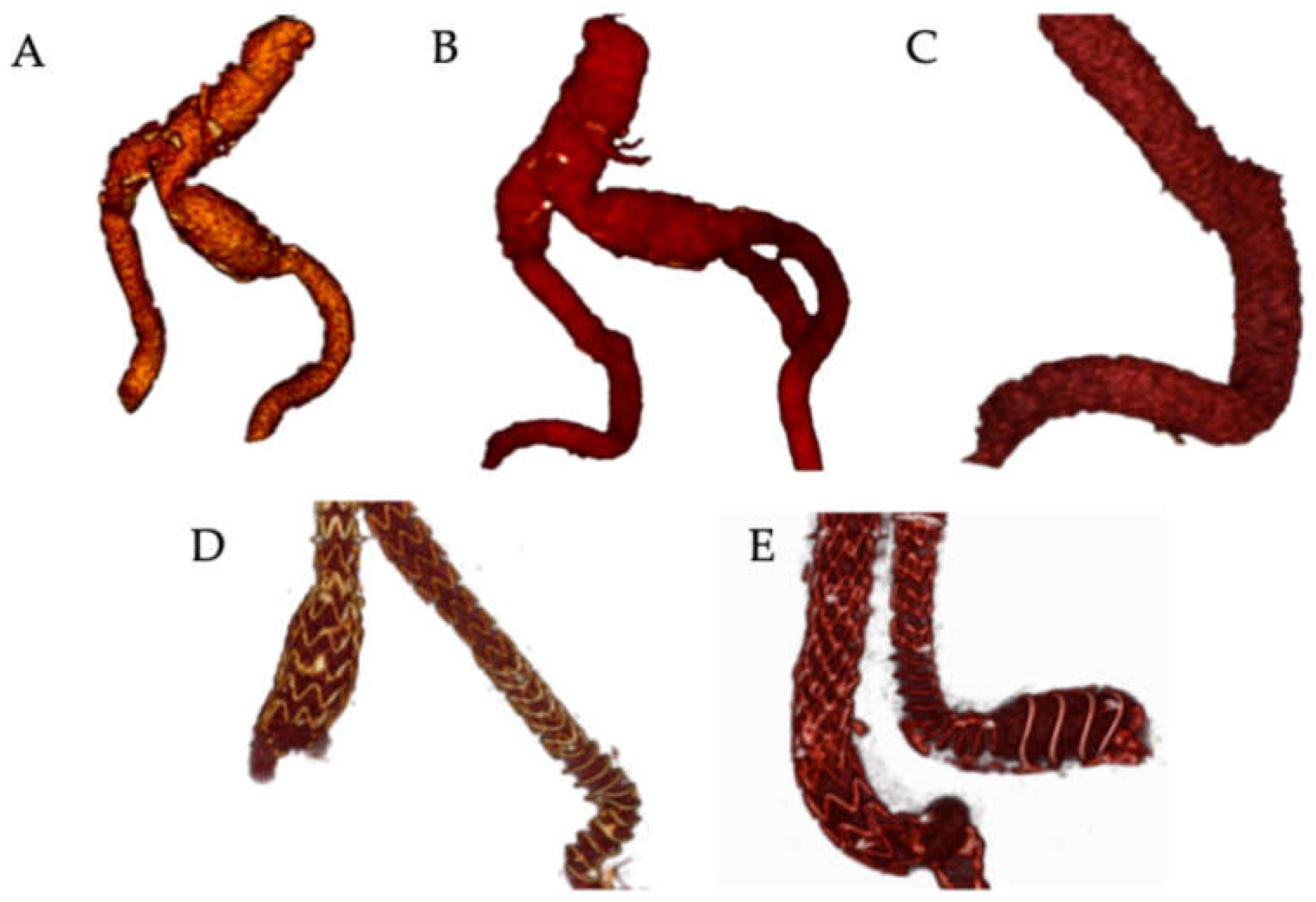
Therefore, the aim of this study was to evaluate the influence of different stent-strut configurations on the hemodynamic performance of commercially available stent-graft limbs deployed in compliant 3D-printed iliac bend phantoms with controlled angulations (Figure 1).

2. Materials and Methods

2.1. Manufacturing of Arterial Models with Angulation

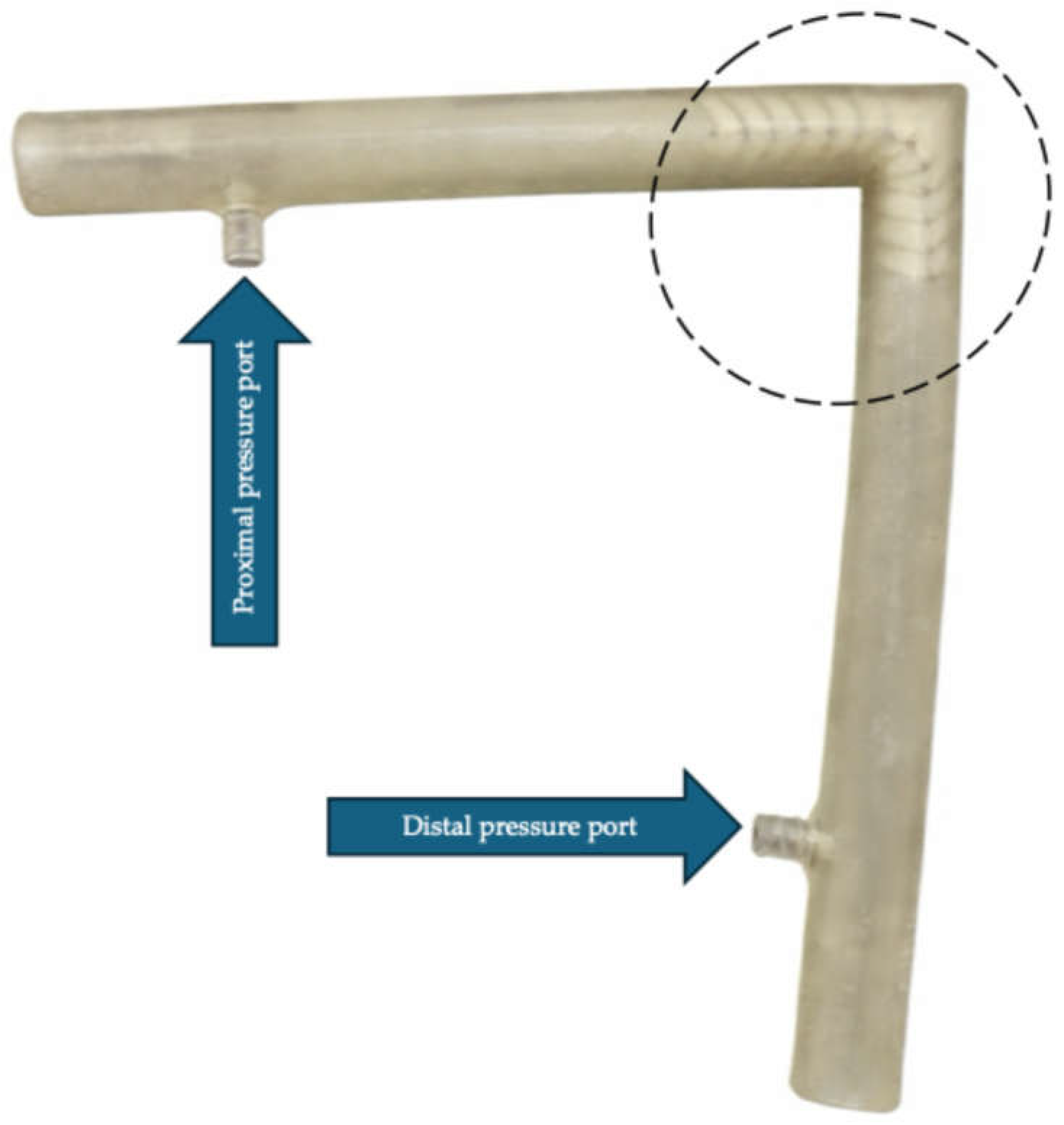
To understand the hemodynamic conditions and biomechanical forces generated by vascular kinking, it was necessary to use compliant arterial models that approximate in vivo conditions. For this purpose, we employed standardized 3D-printed models of iliac arteries with controlled angulations, with different stent-grafts implanted in situ. The 3D models of iliac arteries were designed using Autodesk Fusion 360 (Autodesk Inc., San Rafael, CA, USA) (Figure 2). The model length was 10 cm from each end to the angulated segment.
The flow lumen had a diameter of 11 mm with bends of 75°, 90°, and 105°. The 3D models had Luer-lock connectors at both ends to allow pressure measurement (the connectors were placed approximately 2 cm from the ends of the models). The compliant vessel setting was used to print the models on a J850 Digital Anatomy Printer (Stratasys, Eden Prairie, MN, USA). These steps were performed at the hospital’s 3D-printing medical technology laboratory by staff experienced in generating medical 3D models. The elastic compliant tubes were made from Agilus30TM resin (Stratasys, Eden Prairie, MN, USA).

2.2. Flow Mock System

Stent grafts from four different manufacturers were implanted into the compliant 3D-printed models simulating severe iliac artery angulation. The tested stent grafts were Anaconda (Vascutek, Terumo, Inchinnan, UK), Zenith Spiral-Z (Cook, Limerick, Ireland), Endurant IIs (Medtronic, Dublin, Ireland), and Treo (Terumo Shibuya, Tokyo, Japan). Limbs of 13 mm diameter were used for all stent grafts except Anaconda, for which only a 12 mm diameter option was available. The nominal limb lengths were 80 mm for Anaconda, 82 mm for Endurant II, 80 mm for Treo, and 90 mm for Zenith Spiral-Z. Differences in device diameter and limb length represent a potential confounding factor in the hemodynamic comparison. In vitro, hemodynamics were replicated in the lumen of the 3D models using a Harvard Apparatus pump (Holliston, MA, USA). Flow pressure before and after the stent-graft limbs was measured using pressure sensors (Trandomed, Ningbo, China). Pump parameters were adjusted to deliver a stroke volume of 15 mL at a rate of 60 beats per minute, with a systolic duration of 0.33 s and a diastolic duration of 0.67 s. The flow loop included a fluid reservoir and connecting tubing, forming a closed circulation system that allowed stable pulsatile flow conditions during measurements. Pressure sensors were positioned approximately 2 cm proximally and distally to the angulated segment. Each stent-graft deployment and measurement was repeated five times for each angulation model. The pressure drop ratio was calculated for each stent-graft and angulation model and is summarized in Table 1.
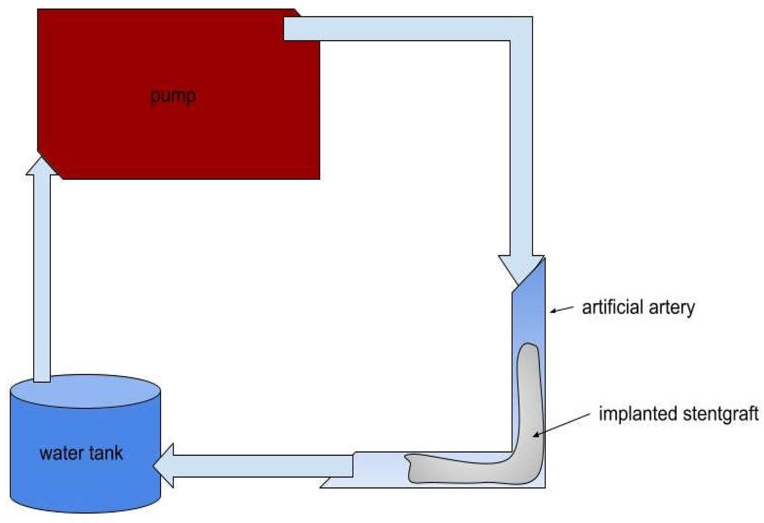
Figure 3 shows the bench model of the hemodynamic system used to test the stent-grafts implanted into the angulated iliac artery models. For the blood analog, a 60:40 water-glycerol mixture was used. The fluid was heated to approximately 36 °C before perfusion, while measurements were performed at room temperature.

2.3. Doppler Ultrasound Technique

Doppler Ultrasound measurements of flow velocity were performed at three points of the model: before the stent-graft implantation site (approximately 2 cm before the graft), within the stent-graft (approximately 2 cm before the model angulation), and within the stent-graft after the angulation (approximately 2 cm distal to the bend). A Toshiba Aplio 400 ultrasound system (Canon Medical Systems, Tokyo, Japan) with a linear ultrasonographic probe was used for this purpose. Each stent-graft implantation was repeated five times in the same angulation model, and the pressures and velocities were recorded (Table 2). The entire procedure was repeated for each tested angulation. All stent-graft deployments were performed under visual guidance by a vascular surgeon with 12 years of experience in EVAR procedures, leveraging the semi-transparency of the printed models. All Doppler ultrasound measurements were performed by a radiologist with 12 years of experience in vascular imaging.

2.4. Statistical Analysis

The mean, median, standard deviation (SD), and confidence interval (CI) were used to present continuous variables. The pressure drop across the stent-graft was expressed as the ratio of distal to proximal pressure measurements. To present the increase in flow velocity, the ratio of the values obtained after the kinking to those measured was used. A similar velocity ratio was used to quantify the speed augmentation induced by the stent-graft, defined as the velocity in the proximal segment of the endograft divided by the velocity in the proximal segment of the elastic model. The normality of distribution was verified using the Shapiro–Wilk test, and the homogeneity of variance was assessed using the Levene test. The Kruskal–Wallis test was used for variables with non-normal distributions or unequal variances, while the F-test was used for variables with normal distributions and equal variances. Multiple comparisons were performed using the Kruskal–Wallis post hoc test and the NIR test. A p-value < 0.05 was considered statistically significant. All computations were performed using Statistica 13.3 (TIBCO Software Inc., Palo Alto, CA, USA). No formal a priori power analysis was performed, and the study should therefore be considered exploratory in nature.

3. Results

3.1. Performance at a 75-Degree Angle

At the 75° angulation, the smallest pressure drop was observed for the Anaconda stent-graft (pressure ratio 0.81), whereas lower ratios were recorded for Treo (0.67) and Zenith Spiral-Z (0.63). These differences were statistically significant (p = 0.0197 and p = 0.0011, respectively) (Table 1).
Table 1. Pressure drop ratio for different stent-grafts at angulations of 75°, 90°, and 105°. CI—confidence interval; SD—standard deviation.
EndograftAngle
(°)
Mean Lower
95% CI
Upper 95% CIMedianSD
Spiral Z750.620.570.670.640.04
Endurant II750.740.720.750.740.01
Treo750.660.620.700.680.03
Anaconda750.810.780.830.790.02
Spiral Z900.690.600.780.680.07
Endurant II900.410.170.650.460.19
Treo900.690.630.760.680.05
Anaconda900.870.850.890.870.01
Spiral Z1050.620.530.710.600.07
Endurant II1050.730.630.830.770.08
Treo1050.660.550.770.680.09
Anaconda1050.840.810.860.830.02
No statistically significant differences in the post-angulation velocity ratio were observed among the tested devices at this angle. Raw pressure and velocity measurements are presented in Table 2.
Table 2. Raw pressure and velocity measurements obtained during in vitro flow experiments for each stent-graft and angulation model.
EndograftAngle (°)MeasurementPressure Before Angulation (mmHg)Pressure After Angulation (mmHg)Velocity Before Stent-Graft (cm/s)Velocity in Stent-Graft Before Angulation (cm/s)Velocity in Stent-Graft After Angulation (cm/s)
Spiral Z7519060100150280
Spiral Z752895090200330
Spiral Z7538555100220310
Spiral Z754845485230370
Spiral Z755825190220290
Endurant II75110378110170250
Endurant II7529874105150350
Endurant II7539973105180290
Endurant II754956990190430
Endurant II7558966100200295
Treo7519565110180440
Treo7521027090200320
Treo7538756100190440
Treo75410163100170350
Treo7559364105220360
Anaconda75110885120230370
Anaconda75210987115210340
Anaconda75310789120230385
Anaconda75410487115260350
Anaconda75511188120250350
Spiral Z9019677120150300
Spiral Z9028555110125300
Spiral Z9039565120170420
Spiral Z9049166100220300
Spiral Z90512476100130450
Endurant II9011253070200490
Endurant II902954480200400
Endurant II9031503065170430
Endurant II904924593170550
Endurant II9059564110170380
Treo90110270100150550
Treo9028152110140460
Treo9038868120210450
Treo9049367120170400
Treo905966580140470
Anaconda901938395185260
Anaconda9029986105250370
Anaconda9039785110260315
Anaconda90410490100250340
Anaconda90510388105210300
Spiral Z10519665100150230
Spiral Z1052966870190400
Spiral Z10531036280200320
Spiral Z1054965380220330
Spiral Z10551005685240390
Endurant II105111770105190360
Endurant II1052806470270320
Endurant II1053917080150290
Endurant II1054977590200280
Endurant II1055866290190320
Treo1051995078230600
Treo10521027090220410
Treo10531006890220480
Treo1054956790190540
Treo10551168490150370
Anaconda10519981124230390
Anaconda10529982130265315
Anaconda10539481125250320
Anaconda105410184130240370
Anaconda105510086125225390

3.2. Performance at a 90 Degree Angle

At the 90° angulation, the Anaconda stent-graft showed the highest-pressure ratio (0.87), indicating the lowest pressure loss, whereas the Endurant II device showed the lowest ratio (0.41). This difference was statistically significant (p = 0.0007). No significant differences were observed among the remaining devices.
Higher increases in post-angulation flow velocity were observed for Zenith Spiral-Z, Endurant II, and Treo compared with Anaconda, reaching statistical significance (p = 0.0155, p = 0.0064, and p = 0.004, respectively) (Table 1).

3.3. Performance at a 105-Degree Angle

At 105° angulation, the highest-pressure ratio was again observed with the Anaconda stent-graft (0.84), while lower ratios were observed with Zenith Spiral-Z (0.62) and Treo (0.66). These differences were statistically significant in comparison with the Anaconda device.
Similarly, the increase in the post-angulation velocity ratio was lowest for the Anaconda stent-graft (1.48), whereas the highest value was recorded for the Treo device (2.4), with statistical significance (p = 0.0327) (Table 1).

3.4. In-Stent Graft Flow Velocity Ratio

The in-stent-graft velocity ratio was defined as the ratio of the velocity in the proximal segment of the stent-graft to the velocity measured in the proximal segment of the elastic model. All tested stent-grafts increased flow velocity within the graft lumen. Mean in-stent velocity ratios were 2.0, 2.1, 1.9, and 2.1 for Zenith Spiral-Z, Endurant II, Treo, and Anaconda, respectively (Table 3). No significant differences were observed among the tested devices.

4. Discussion

Stent-graft limb occlusion due to distortion or deformation remains an important reason for secondary intervention after EVAR. Apart from the anatomical factors such as severe angulation or tortuosity of the iliac arteries, reduced vessel diameter due to stenosis with or without calcifications, or a narrow aortic bifurcation, technical aspects of implantation (e.g., excessive oversizing or extension to the external iliac artery) and device-related features may also predispose to iliac limb occlusion [8]. Currently available stent-grafts differ in their stent-strut configurations, including Z-stent, M-stent, O-ring, and spiral designs, which may influence their flexibility and adaptation to complex iliac anatomy, particularly in cases of pronounced arterial angulation [16].
In the present experimental study, we evaluated the hemodynamic performance of four commercially available stent-grafts in compliant 3D-printed iliac bend models with controlled angulations. The obtained results suggest that the device with O-ring-based strut configuration demonstrated more favorable hemodynamic performance under the tested conditions, reflected by higher pressure ratios and lower post-angulation velocity increases compared with other evaluated designs. These findings suggest that stent-strut morphology may influence graft conformability and flow characteristics in angulated vascular segments. However, because the present analysis was limited to pressure and velocity measurements, the mechanisms underlying these differences cannot be fully explained.
The observed results were in line with the instruction for use (IFU) of the Anaconda endograft, which allows implantation in aneurysm neck angulations up to 90°, representing one of the most permissive criteria among currently available devices [17]. In contrast, the IFUs for Endurant II, Treo, and Zenith typically recommended lower angulations [18,19,20]. However, it should be emphasized that IFU criteria primarily refer to proximal neck anatomy, while detailed limits for iliac artery angulation are rarely specified. Moreover, the stent-strut configuration of the main body may differ from that of the iliac limb. For example, the Cook main body employs Z-stents but may be combined with Spiral-Z limbs. Importantly, a substantial proportion of EVAR procedures are performed outside IFU criteria, highlighting the clinical relevance of understanding device behavior in challenging anatomies [21].
Previous experimental and numerical studies also demonstrated that stent-graft design influences mechanical performance in curved vessels. Demanget et al. used finite element analysis to compare commercially available devices and reported that annular stent configurations exhibited greater flexibility and reduced lumen reduction in severe bends compared with Z-stent designs [12]. Similarly, Lin’s group showed that circular or ring-supported stent-grafts were less prone to twisting and fabric damage than Z-stent-supported devices [13].
Clinically, the overall incidence of limb thrombosis after EVAR ranges from approximately 1.4 to 8% and depends on a combination of anatomical and device-related factors. Anatomical risk factors include iliac tortuosity or kinking, severe angulation, small-vessel diameter, or a calcified and narrowed bifurcation [4]. Mechanical graft-related factors, such as twisting, migration, or extrinsic compression, may also contribute to occlusion [14]. The increased pressure loss observed in highly angulated models in the present study may reflect adverse flow conditions. However, its relationship to in vivo thrombosis cannot be determined in this in vitro setup. A systematic review by Coelho et al. reported that endograft limb kinking accounted for 42.8% of limb occlusion cases, suggesting that geometric deformation plays a major role in limb failure [22].
Several clinical studies further indicate that device design may influence limb patency. Shintani et al. reported lower occlusion rates in patients treated with helical stent-supported limbs on the external iliac artery [15]. Additional placement of a bare-metal stent has also been suggested as a protective measure in cases at high risk of limb compression or kinking [23]. Marques de Marino’s group similarly observed higher occlusion rates with Z-stent-supported designs compared with more flexible designs, and registry-based analyses have shown variability in limb occlusion rates across devices [24,25]. Although the present in vitro results cannot be directly translated into clinical outcomes, they suggest that device flexibility and conformability may influence limb behavior in angulated anatomy under controlled experimental conditions.
This study has several limitations that should be acknowledged. First, the experiments were performed in simplified compliant arterial phantoms with a single controlled angulation rather than full patient-specific iliac geometries. The models did not include the stent-graft main body or aortic bifurcation, which may influence limb positioning and mechanical interactions in vivo. Previous computational and imaging-based studies have shown that patient-specific anatomy, device configuration, and boundary conditions may substantially influence predicted stent-graft behavior and local hemodynamic parameters [26,27]. Therefore, the present setup should be interpreted as a partial model of iliac limb behavior under standardized geometric conditions rather than as a realistic EVAR reconstruction or direct simulation of clinical anatomy. This is particularly important because post-EVAR thrombotic complications have been linked to both aorto-iliac geometry and local hemodynamic disturbances in patient-specific analyses [27,28]. Accordingly, the present findings cannot be directly extrapolated to clinical limb occlusion risk. Second, only iliac limbs with diameters of 12–13 mm were tested, reflecting commonly used clinical sizes, but not covering the full range of available diameters. In addition, the Anaconda device was tested with a 12 mm limb, whereas the other stent-grafts were tested with 13 mm limbs, because no 13 mm Anaconda option was available. The nominal limb lengths also differed between devices (80 mm for Anaconda, 82 mm for Endurant II, 80 mm for Treo, and 90 mm for Zenith Spiral-Z). These differences in diameter represent a potential confounding factor and should be considered when interpreting the observed hemodynamic differences, as the results cannot be attributed solely to stent-strut morphology. Device sizing and oversizing may influence endograft behavior and hemodynamics, warranting further investigation. Third, although the compliant material used for printing approximates arterial elasticity, it does not fully reproduce the mechanical properties of diseased human vessels, particularly in the presence of calcifications or stenosis. Fourth, perfusion was performed using a water-glycerol mixture representing a Newtonian fluid, which does not fully replicate the non-Newtonian rheological properties of blood and may affect detailed flow patterns. Fifth, the present analysis was restricted to pressure and flow velocity measurements and did not include wall shear stress, detailed flow pattern assessment, or lumen deformation analysis, which limits mechanistic interpretation of the observed differences between stent-graft designs. Sixth, each experimental setting was repeated five times, and no formal power analysis was performed. Therefore, the statistical comparisons should be interpreted with caution, particularly in the context of multiple comparisons across devices and angulations. Finally, long-term geometric changes in implanted limbs, such as increased curvature or reduced inter-ring distance, reported in follow-up studies of Anaconda devices, were not addressed in this short-term experimental setup [29].
Despite these limitations, the controlled in vitro design allowed direct comparison of different stent-strut configurations under identical flow and geometric conditions, providing experimental insight into the relationship between graft structure and global hemodynamic behavior in angulated iliac segments. These findings may provide experimental insights into device behavior in challenging iliac anatomy and should be considered hypothesis-generating bench data for future clinical studies.

5. Conclusions

The results of this experimental study suggest that stent-grafts with an O-ring-based strut configuration may provide more favorable hemodynamic performance in severely angulated iliac segments under controlled in vitro conditions. This design demonstrated higher pressure ratios and lower post-angulation velocity increases compared with other tested configurations, indicating improved conformability in the evaluated models.
These findings suggest that stent-graft structural design may influence device behavior in relation to vessel geometry under controlled in vitro conditions. These observations should be interpreted as hypothesis-generating bench data and may be relevant for future investigations of EVAR in angulated iliac anatomy.
Furthermore, compliant 3D-printed vascular phantoms may serve as a useful experimental tool for evaluating stent-graft behavior under challenging anatomical conditions and for supporting future device optimization. Additional studies incorporating more complex vascular geometries, full aorto-iliac reconstructions, advanced hemodynamic analyses such as wall shear stress and flow pattern assessment, and clinical and longitudinal outcomes such as limb patency and thrombosis are required to determine the translational relevance of these findings.

Author Contributions

Conceptualization, M.W. and P.R.; methodology, M.W. and P.R.; formal analysis, M.W. and P.R.; investigation, M.W. and P.R.; data curation, M.W. and P.R.; writing—original draft preparation, M.W.; writing—review and editing, M.W., P.S. and P.R.; supervision, M.W., P.R., A.K., M.K., A.F. and P.G.; project administration, M.W., P.R., A.K., M.K., A.F. and P.G. All authors have read and agreed to the published version of the manuscript.

Funding

This research received no external funding.

Institutional Review Board Statement

According to the decision of the Bioethics Committee of the Pomeranian Medical University in Szczecin (KB.008.131.2026, dated 8 April 2026), this in vitro experimental study did not require ethics committee approval, as it did not involve human participants or animal subjects.

Informed Consent Statement

Patient consent was waived since the research did not involve human participants or animal subjects.

Data Availability Statement

The datasets analyzed during the current study are available from the corresponding author upon reasonable request.

Acknowledgments

The 3D-printed vascular models used in this study were produced at the Medical 3D Technologies Center of University Clinical Hospital No. 2 in Szczecin, where three of the co-authors (P.R., M.W., and P.S.) are employed, using a J850 Stratasys Digital Anatomy 3D Printer (Stratasys, Eden Prairie, MN, USA). The stent-grafts used in this study were sourced through routine clinical channels. No manufacturer provided material, financial, or technical support for this study.

Conflicts of Interest

The authors declare no conflicts of interest.

Abbreviations

The following abbreviations are used in this manuscript:
3DThree-Dimensional
AAAAbdominal Aortic Aneurysm
CIACommon Iliac Artery
CIConfidence Interval
CTAComputed Tomography Angiography
EIAExternal Iliac Artery
EVAREndovascular Aneurysm Repair
SDStandard Deviation

References

  1. Niklas, N.; Gutowski, P.; Kazimierczak, A.; Rynio, P. Abdominal Aortic Aneurysm Morphology as an Essential Criterion for Stratifying the Risk of Aneurysm Rupture. J. Clin. Med. 2022, 11, 933. [Google Scholar] [CrossRef]
  2. Aggarwal, S.; Qamar, A.; Sharma, V.; Sharma, A. Abdominal aortic aneurysm: A comprehensive review. Exp. Clin. Cardiol. 2011, 16, 11–15. [Google Scholar]
  3. Taudorf, M.; Jensen, L.P.; Vogt, K.C.; Grønvall, J.; Schroeder, T.V.; Lönn, L. Endograft Limb Occlusion in EVAR: Iliac Tortuosity Quantified by Three Different Indices on the Basis of Preoperative CTA. Eur. J. Vasc. Endovasc. Surg. 2014, 48, 527–533. [Google Scholar] [CrossRef]
  4. Wanhainen, A.; Verzini, F.; Van Herzeele, I.; Allaire, E.; Bown, M.; Cohnert, T.; Dick, F.; van Herwaarden, J.; Karkos, C.; Koelemay, M.; et al. Editor’s Choice—European Society for Vascular Surgery (ESVS) 2019 Clinical Practice Guidelines on the Management of Abdominal Aorto-iliac Artery Aneurysms. Eur. J. Vasc. Endovasc. Surg. 2019, 57, 8–93. [Google Scholar] [CrossRef]
  5. Hu, D.K.; Pisimisis, G.T.; Sheth, R.A. Repair of abdominal aortic aneurysms: Preoperative imaging and evaluation. Cardiovasc. Diagn. Ther. 2018, 8, S157–S167. [Google Scholar] [CrossRef]
  6. Mulay, S.; Geraedts, A.C.M.; Koelemay, M.J.W.; Balm, R.; ODYSSEUS study group. Type 2 Endoleak With or Without Intervention and Survival After Endovascular Aneurysm Repair. Eur. J. Vasc. Endovasc. Surg. 2021, 61, 779–786. [Google Scholar] [CrossRef]
  7. Madigan, M.C.; Singh, M.J.; Chaer, R.A.; Al-Khoury, G.E.; Makaroun, M.S. Occult type I or III endoleaks are a common cause of failure of type II endoleak treatment after endovascular aortic repair. J. Vasc. Surg. 2019, 69, 432–439. [Google Scholar] [CrossRef] [PubMed]
  8. Schoretsanitis, N.; Georgakarakos, E.; Argyriou, C.; Ktenidis, K.; Georgiadis, G.S. A critical appraisal of endovascular stent-grafts in the management of abdominal aortic aneurysms. Radiol. Med. 2017, 122, 309–318. [Google Scholar] [CrossRef] [PubMed]
  9. Voûte, M.T.; Bastos Gonçalves, F.M.; van de Luijtgaarden, K.M.; Klein Nulent, C.G.A.; Hoeks, S.E.; Stolker, R.J.; Verhagen, H.J. Stent graft composition plays a material role in the postimplantation syndrome. J. Vasc. Surg. 2012, 56, 1503–1509. [Google Scholar] [CrossRef] [PubMed]
  10. Maleckis, K.; Anttila, E.; Aylward, P.; Poulson, W.; Desyatova, A.; MacTaggart, J.; Kamenskiy, A. Nitinol Stents in the Femoropopliteal Artery: A Mechanical Perspective on Material, Design, and Performance. Ann. Biomed. Eng. 2018, 46, 684–704. [Google Scholar] [CrossRef]
  11. Costa, D.; Andreucci, M.; Ielapi, N.; Serraino, G.F.; Mastroroberto, P.; Bracale, U.M.; Serra, R. Infection of Vascular Prostheses: A Comprehensive Review. Prosthesis 2023, 5, 148–166. [Google Scholar] [CrossRef]
  12. Demanget, N.; Duprey, A.; Badel, P.; Orgéas, L.; Avril, S.; Geindreau, C.; Albertini, J.-N.; Favre, J.-P. Finite Element Analysis of the Mechanical Performances of 8 Marketed Aortic Stent-Grafts. J. Endovasc. Ther. 2013, 20, 523–535. [Google Scholar] [CrossRef] [PubMed]
  13. Lin, J.; Guidoin, R.; Du, J.; Wang, L.; Douglas, G.; Zhu, D.; Nutley, M.; Perron, L.; Zhang, Z.; Douville, Y. An in Vitro Twist Fatigue Test of Fabric Stent-Grafts Supported by Z-Stents vs. Ringed Stents. Materials 2016, 9, 113. [Google Scholar] [CrossRef]
  14. Wang, G.; Zhai, S.; Li, T.; Li, X.; Lu, D.; Wang, B.; Zhang, D.; Shi, S.; Zhang, Z.; Liang, K.; et al. Limb graft occlusion following endovascular aortic repair: Incidence, causes, treatment and prevention in a study cohort. Exp. Ther. Med. 2017, 14, 1763–1768. [Google Scholar] [CrossRef]
  15. Shintani, T.; Obara, H.; Matsubara, K.; Hayashi, K.; Hayashi, M.; Ono, S.; Shimogawara, T.; Shibutani, S.; Watada, S.; Sekimoto, Y.; et al. Impact of Stent Graft Design on External Iliac Artery Limb Occlusion Rates After Endovascular Aneurysm Repair: Post-hoc Analysis of a Japanese Multicentre Database. Eur. J. Vasc. Endovasc. Surg. 2019, 58, 839–847. [Google Scholar] [CrossRef]
  16. Georgakarakos, E.; Raptis, A.; Schoretsanitis, N.; Bisdas, T.; Beropoulis, E.; Georgiadis, G.S.; Matsagkas, M.; Xenos, M. Studying the Interaction of Stent-Grafts and Treated Abdominal Aortic Aneurysms. J. Endovasc. Ther. 2015, 22, 413–420. [Google Scholar] [CrossRef]
  17. AnacondaTM AAA Stent Graft System Instructions for Use. Terumo Aortic, Inchinnan, UK. Available online: https://terumoindiaskilllab.com/assets/pdf/Att.7_IFU_Action%209d_Anaconda-Lo-Pro-cuff.pdf (accessed on 5 May 2026).
  18. Medtronic. EndurantTM II/ EndurantTM IIs Stent Graft System Instructions for Use. Available online: www.medtronic.com/manuals (accessed on 5 May 2026).
  19. U.S. Food and Drug Administration. Summary of Safety and Effectiveness Data (SSED): TREO® Abdominal Stent-Graft System, PMA P190015. Available online: https://www.accessdata.fda.gov/cdrh_docs/pdf19/P190015B.pdf (accessed on 5 May 2026).
  20. Cook Medical. Zenith®Spiral-Z® AAA Iliac Leg Graft. Available online: https://www.cookmedical.eu/products/54a05f86-0dc1-407e-b667-0a5d09df3efb/ (accessed on 5 May 2026).
  21. Walker, J.P.; Tucker, L.-Y.; Goodney, P.; Hua, H.; Okuhn, S.; Rhoades, A.; Hill, B.; Chang, R.W. Adherence to EVAR Device Instructions for Use (IFU) Guidelines Has No Impact on Long-Term Outcomes. J. Vasc. Surg. 2014, 60, 546. [Google Scholar] [CrossRef]
  22. Coelho, A.; Nogueira, C.; Lobo, M.; Gouveia, R.; Campos, J.; Augusto, R.; Coelho, N.; Semião, A.C.; Ribeiro, J.P.; Canedo, A. Impact of Post-EVAR Graft Limb Kinking in EVAR Limb Occlusion: Aetiology, Early Diagnosis, and Management. Eur. J. Vasc. Endovasc. Surg. 2019, 58, 681–689. [Google Scholar] [CrossRef]
  23. Oshin, O.A.; Fisher, R.K.; Williams, L.A.; Brennan, J.A.; Gilling-Smith, G.L.; Vallabhaneni, S.R.; McWilliams, R.G. Adjunctive Iliac Stents Reduce the Risk of Stent-Graft Limb Occlusion Following Endovascular Aneurysm Repair With the Zenith Stent-Graft. J. Endovasc. Ther. 2010, 17, 108–114. [Google Scholar] [CrossRef]
  24. Marques de Marino, P.; Ibraheem, A.; Gafur, N.; Mufty, H.; Schubert, N.; Verhoeven, E.L.; Katsargyris, A. Limb Occlusion Rate after EVAR With Individualized Graft Limb Selection and a Liberal Protocol of Primary Relining. Ann. Vasc. Surg. 2021, 75, 445–454. [Google Scholar] [CrossRef]
  25. Bogdanovic, M.; Stackelberg, O.; Lindström, D.; Ersryd, S.; Andersson, M.; Roos, H.; Siika, A.; Jonsson, M.; Roy, J. Limb Graft Occlusion Following Endovascular Aneurysm Repair for Infrarenal Abdominal Aortic Aneurysm with the Zenith Alpha, Excluder, and Endurant Devices: A Multicentre Cohort Study. Eur. J. Vasc. Endovasc. Surg. 2021, 62, 532–539. [Google Scholar] [CrossRef] [PubMed]
  26. Derycke, L.; Avril, S.; Millon, A. Patient-Specific Numerical Simulations of Endovascular Procedures in Complex Aortic Pathologies: Review and Clinical Perspectives. J. Clin. Med. 2023, 12, 766. [Google Scholar] [CrossRef]
  27. Ngo, D.H.A.; Lee, K.H.; Lee, J.I.; Hwang, H.P.; Han, Y.M.; Kwak, H.S. Impact of aorto-iliac hemodynamics and geometry on thrombotic complications following abdominal aortic endovascular aneurysm repair. Eur. J. Radiol. 2025, 187, 112116. [Google Scholar] [CrossRef] [PubMed]
  28. Liu, Y.; Ju, Z.; Liu, T.; Xie, S.; Sheng, C.; Liu, S.; Wu, K.; Yun, Z.; Qiu, J.; Wang, W. Computational Fluid Dynamics Predicting Intraprosthetic Thrombus Formation and Burden Following Endovascular Aortic Repair: A Two-Center Retrospective Study. Ann. Vasc. Surg. 2026, 127, 130–141. [Google Scholar] [CrossRef] [PubMed]
  29. Simmering, J.A.; Geelkerken, R.H.; Slump, C.H.; Koenrades, M.A. Geometrical changes in Anaconda endograft limbs after endovascular aneurysm repair: A potential predictor for limb occlusion. Semin. Vasc. Surg. 2020, 32, 94–105. [Google Scholar] [CrossRef]
Figure 1. Computed Tomography Angiography (CTA) reconstructions of angulated iliac arteries before and after stent-graft implantation. (A,B); CTA angulated iliac arteries before implantation of stent-graft; (C) CTA angulated left iliac and external iliac artery before implantation of stent-graft; (D) CTA angulated iliac arteries after stent-graft implantation (Endurant II and Anaconda—angulated left EIA); (E) CTA angulated iliac arteries after stent-graft implantation (Endurant II—angulated right CIA and Anaconda—angulated left CIA/EIA). CIA—common iliac artery; EIA—external iliac artery.
Jcm 15 03768 g001
Figure 2. Representative 3D-printed phantom of a severely angulated arterial segment with an implanted stent-graft (dashed circle) used for fluid-dynamic simulation of physiological arterial flow. Proximal and distal pressure measurement connectors (arrows) are indicated.
Jcm 15 03768 g002
Figure 3. Schematic representation of the flow circulatory system using a computer-controlled gear pump to provide the fluid dynamic simulation of physiological flow through the 3D-printed kinked segment of iliac artery implanted with a selected stent-graft at varying angles. The arrows indicate the direction of fluid flow and identify the main components of the system.
Jcm 15 03768 g003
Table 3. Post-angulation flow velocity ratio for different stent-grafts at angulations of 75°, 90°, and 105°. CI—confidence interval; SD—standard deviation.
EndograftAngle
(°)
MeanLower
95% CI
Upper
95% CI
MedianSD
Spiral Z751.571.31.831.610.22
Endurant II751.831.292.371.610.43
Treo752.011.532.492.060.38
Anaconda751.521.351.711.610.14
Spiral Z902.341.393.292.400.76
Endurant II902.491.913.072.450.46
Treo902.962.123.79 3.290.67
Anaconda901.371.251.50 1.400.10
Spiral Z1051.671.361.98 1.600.25
Endurant II1051.621.222.021.680.32
Treo1052.391.922.86 2.470.38
Anaconda1051.491.181.791.540.24
Disclaimer/Publisher’s Note: The statements, opinions and data contained in all publications are solely those of the individual author(s) and contributor(s) and not of MDPI and/or the editor(s). MDPI and/or the editor(s) disclaim responsibility for any injury to people or property resulting from any ideas, methods, instructions or products referred to in the content.