Abstract
Minimally-invasive therapies are well-established treatment methods for saccular intracranial aneurysms (SIAs). Knowledge concerning fusiform IAs (FIAs) is low, due to their wide and alternating lumen and their infrequent occurrence. However, FIAs carry risks like ischemia and thus require further in-depth investigation. Six patient-specific IAs, comprising three position-identical FIAs and SIAs, with the FIAs showing a non-typical FIA shape, were compared, respectively. For each model, a healthy counterpart and a treated version with a flow diverting stent were created. Eighteen time-dependent simulations were performed to analyze morphological and hemodynamic parameters focusing on the treatment effect (TE). The stent expansion is higher for FIAs than SIAs. For FIAs, the reduction in vorticity is higher (35–75% case 2/3) and the reduction in the oscillatory velocity index is lower (15–68% case 2/3). Velocity is reduced equally for FIAs and SIAs with a TE of 37–60% in FIAs and of 41–72% in SIAs. Time-averaged wall shear stress (TAWSS) is less reduced within FIAs than SIAs (30–105%). Within this study, the positive TE of FDS deployed in FIAs is shown and a similarity in parameters found due to the non-typical FIA shape. Despite the higher stent expansion, velocity and vorticity are equally reduced compared to identically located SIAs.
1. Introduction
Intracranial aneurysms (IAs) are a pathological dilatation occurring in the neurovascular arteries. These IAs carry the risk of rupture, which can lead to subarachnoid hemorrhages resulting in high rates of morbidity or even mortality [1]. Many IAs can be classified as saccular IAs (SIA) due to their balloon-like shape with an identifiable neck separating the aneurysm from the host parent vessel. Hemodynamics and treatment effects within SIAs are part of many past and current studies [2,3,4]. Furthermore, the treatment procedure is well studied and applied in neurointerventional surgery [5,6,7,8,9]. A non-saccular aneurysm, where the aneurysm typically affects the entire circumference of the vessel wall, is referred to as a fusiform IA (FIA). FIAs carry, in addition to rupture risk, the risk of ischemia, due to internal branch occlusion or distal embolization [10,11,12]. Therefore, when treating FIAs, the focus lies on restoring the arterial lumen, on preserving the flow inside the FIA and its internal arteries, and on the prevention of occluding vessels internally branching off within the IA [13]. According to al-Yamany et al. and Park et al. [14,15], FIAs occur within all IAs with an incidence of 3%. Due to this low incidence rate, most studies focus on the typical shape of FIAs when investigating intra-aneurysmal flow and treatment effect [16,17]. The treatment effect on hemodynamic parameters within FIAs that do not show conventional FIA shape need further investigation.
Endovascular therapy, such as the deployment of a flow-diverting stent (FDS), reduces the rupture risk of SIAs by effecting the blood flow entering the aneurysm [8,18]. The goal is to bring the intra-aneurysmal flow to stasis by allowing a thrombus formation to occlude the aneurysm. The wall shear stress (WSS) along the scaffolding is restored to that of the original parent vessel prior to the pathological growth [19], while the goal of FIA treatment is identical, there are few studies to confirm that the hemodynamic outcomes are the same between FIAs and SIAs when treated with a FDS [20,21,22,23]. As found by Barletta et al., flow diversion seems to show most promising results concerning the treatment of FIAs [21]. Saalfeld et al. analyzed FIA’s hemodynamics qualitatively within pathological, healthy, and treated cases [20]. Lv et al. investigated FIA morphology and stent deformation when applying virtual multiple treatment [24]. Griffin et al. performed a clinical study analyzing the outcome of FIA treatment with flow diverter stents focusing on the occlusion rate captured with varying clinical imaging methods [25]. They also compared the occlusion to the treatment outcome of FDS deployed in SIAs and found higher rates in the latter. However, the focus on hemodynamic parameters in FIAs compared to SIA flow and the treatment impact on these parameters is missing in these studies.
Image-based blood flow simulations using computational fluid dynamics (CFD) and virtual treatment approaches provide a great opportunity to model the hemodynamics and the treatment effect without requiring any extra procedure or inconvenience to the patient [26,27,28].
To enhance the knowledge of hemodynamics in non-typically shaped FIAs, this study focused on analyzing these in comparison to equally located SIAs. Thus, the locations within the Circle of Willis do not play a role within the comparison between FIAs and SIAs. Six patient-specific IAs are taken into account in this study. Besides the pathological hemodynamics, the treatment effect and the physiological flow was analyzed and compared among the FIA and SIA cases. To study this, each case was virtually treated with a FDS and the healthy counterpart manually created. The aim is to understand the difference in the flow fields within non-typically shaped FIAs compared to SIAs and the comparability of the impact of treatment onto these flow fields, respectively.
2. Materials and Methods
2.1. Patient Cohort
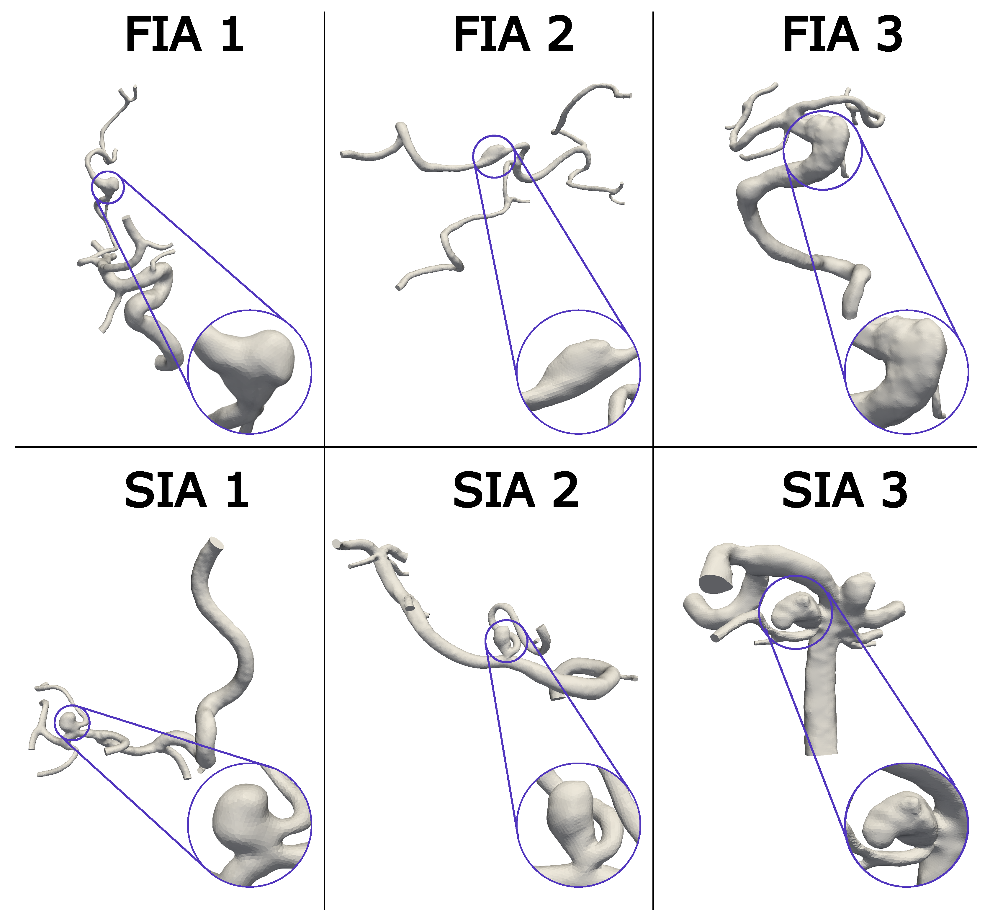
Six patients in total were enrolled in this study, including three FIA and SIA cases occurring in the Circle of Willis, respectively, (FIA/SIA 1–3). The chosen FIA and SIA cases 1–3 are shown in Figure 1 with the FIAs in the top and the SIAs in the bottom, comprising different shapes and sizes. The whole vasculature is shown with a detailed IA view for each case. Regardless of the aspect ratio, SIAs typically exhibit a small neck when compared to the volume of the dome or another length scale of the aneurysm. However, FIAs are, by definition, circumferential, which means the neck area to aneurysm volume ratio is larger than for SIAs and the vessel is affected all around [14,29]. This means the flow has an increased chance of gently expanding into an untreated fusiform aneurysm rather than a saccular case in which an inflow jet creating a wall-impingement zone is not uncommon. Because FIAs are so rare, only three could be obtained with appropriate imaging from a database of at least 300 IAs. Nevertheless, due to a non-balloon-shape without an entire circumferential extension of the FIA vessel, these FIAs feature a non-typical shape.
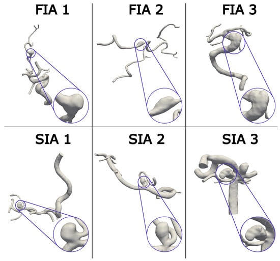
Figure 1.
Visualization of the aneurysm cohort with the FIAs in the first row and SIAs in the second row. A magnification of each IA is provided, to give an overview of the different shapes. Notice the complex vasculature considering the patient-specific anatomy proximal and distal to the IAs.
From the mentioned available database, the choice of the opposed SIA was made based on similar artery (Middle Cerebral Artery—MCA, Vertebral Artery—VA, Basilar Artery—BA), location on and diameter of the vessel (to match flow rates), and size (aspect ratio (AR) and volume) in that order. Although we were searching the database of 300 IAs, not every criterion to match the location could be met exactly and a few drawbacks such as the location on different branches had to be accepted. Even with this database, not all cases were captured with the same imaging technique. The corresponding SIA was chosen to match the FIA as closely as possible. FIA/SIA 1 are located at the MCA and were captured with three-dimensional digital subtraction angiography (3D DSA) with a resolution of 0.28 × 0.28 × 0.28 mm3. Case 2 is located at the left VA. FIA 2 was captured with computer tomography with a resolution of 0.47 × 0.47 × 0.47 mm3 and SIA 2 with 3D DSA at a resolution of 0.15 × 0.15 × 0.15 mm3. Case 3 is located on the BA, and FIA 3 was captured with 3D DSA (0.36 × 0.36 × 0.36 mm3). The corresponding SIA 3 was imaged using 3D DSA as well with a resolution of 0.28 × 0.28 × 0.28 mm3.
2.2. Virtual Stenting, Vessel Reconstruction, and Aneurysm Sac Definition
To allow for an overall population comparison, as well as a comparison within each case, the hemodynamics in each IA are compared to the hemodynamics of the same patient within the treated vasculature and the healthy vasculature (aneurysm virtually removed from the parent vessel).
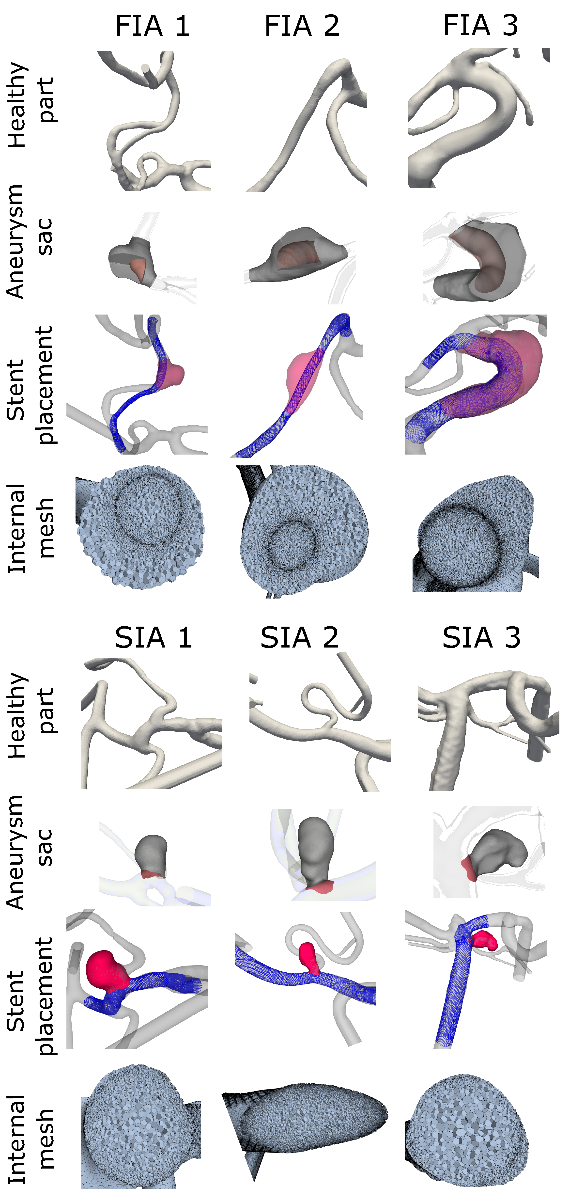
A previously-verified fast virtual stenting approach [30] was applied allowing different stent configurations to be replicated in each case within minutes on a personal laptop. The software is based on geometric deformations and produces realistic deployment with decent wall apposition. First, the geometry was discretized and voxelized before a centerline was created and optimized. The stent was then deployed without retaining the circular cross-section which allows for the shortening or lengthening based on the average radius along the deploying stent. A PED, comprised of 48 wires with a tine radius of 19 m, was modeled for each case. This practice allowed for precise placement and positioning within the vessel that will affect the flow in a realistic manner (see Figure 2, FDS shown in blue). Stent sizing for each case was determined by an experienced neurointerventionalist.

Figure 2.
Aneurysm cohort depicting FIAs in the top four rows and SIAs in the lower four rows with the manually created healthy vasculature (healthy part) on top rows. Second rows show resulting aneurysm domain, used for post processing (aneurysm sac). The sac is shown in gray with surfaces within the FIA cases to visualize the internal boundary of the vessel. The treated version of FIA/SIA is shown in the third row with the pathological aneurysm sac in red and the FDS in blue (stent placement). In the last row an insight into the internal mesh used for the hemodynamic simulation is presented.
To restore the original parent vessel, prior to aneurysm initiation and growth, a healthy version of each case was created with the guidance of the same neurointerventionalist. For this recreation, the aneurysm sac was manually removed from the vessel using the open-source design software Blender (v2.82, Blender Foundation, The Netherlands). The remaining vessel was then smoothed to match the parent vessel surface. Moreover, under consideration of the complete vasculature the healthy vessel formation was manually reconstructed (see Figure 2: healthy part). Since this was carried out without using automated tools, the precision was checked and achieved by consulting a neurointerventionalist.
To perform a precise analysis of the flow-related parameters, the volumetric aneurysm sac and the accompanying dome area were defined for each case. The healthy vessel aided in the definition of the aneurysm sac. First, the healthy vessel was expanded equally in all directions until it was fully intersecting the aneurysm, occluding it from the parent vessel. The healthy vessel volume was then cut from the pathological geometry, so that only the aneurysm sac (volume and surface) remained. Second, if any bifurcating arteries were coming from the aneurysm, they were virtually removed and smoothed. The remaining domain, which was then defined as the aneurysm for post-processing purposes, is presented in Figure 2 (aneurysm sac).
2.3. Hemodynamic Simulation
Each case, FIA/SIA 1–3, was analyzed for the pathological (P), treated (T), and healthy (H) condition. Overall, 18 hemodynamic simulations were carried out within this study to analyze the intra-aneurysmal flow within FIA/SIA. For the spatial discretization as well as for the simulations the fluid dynamics solver StarCCM+ (v2021.1, Siemens, Munich, Germany) was used. The mesh has a global minimum and base size of 0.0375/0.15, 0.0375/0.15, and 0.01/0.2 mm for the H, P, and T models. Tetrahedral cells along with 3 boundary layers expanding at a rate of 1.3 were used to construct the H and P models. The stent was meshed to a precision between 0.01 and 0.02 mm, then polyhedral cells with a stretch of 1.3 were used to mesh the T models. This has been shown to be sufficient by a previous mesh convergence study of treated and untreated models [31]. The resulting cell count ranged from 0.27 to 2.94 million cells for the untreated cases and from 0.44 to 9.03 million cells for the treated ones.
Walls were assumed to be rigid and blood to be incompressible and Newtonian with a density of 1055 kg/m3 and a viscosity of 0.004 .
Inlet boundary conditions were set transient with a mass flow rate captured from a healthy proband in a previous study [32]. For each model, the same mass flow rate was used, with the magnitude scaled according to the specific inlet cross sectional area [33]. This is to prevent the same impact of the mass flow rate onto the inlet flow velocity. Inlets were extended to ensure a fully developed flow profile [34]. A splitting value was set at each outlet calculated with an in-house flow splitting method specific for each vessel model [35]. The splitting method was previously proofed to be stable and realistic [36].
2.4. Morphological and Stent Analysis
Stent and vessel analysis were performed using VMTK (v1.3, vmtk.org) to obtain centerlines and radii. StarCCM+ and MATLAB (R2022a, MathWorks Inc., Natick, MA, USA) were used to create envelopes of the stent, aneurysm, and vessel volumes. Matlab was also used to process the data. Regarding the morphological analysis, the aneurysm volume and stent area were calculated using the assessed envelopes. From this, the area to volume ratio was derived. Concerning the stent analysis, the mean and maximum stent expansion was derived for each case. This stent expansion was calculated based on the deployed stent diameter compared to the given stent diameter using a percent change score
The nominal diameter was the manufacturer’s specification for the optimal vessel size the stent should be deployed in. For the analysis, the stent expansion was only considered along the part of the vessel comprising the aneurysm neck. This is because stent lengthening or foreshortening can be drastically changed based solely on the vessel morphology. This allows for a direct comparison between the morphological response of SIAs and FIAs to the treatment.
2.5. Hemodynamic Analysis
Parameter values were qualitatively and quantitatively evaluated in EnSight (2019 R3, ANSYS Inc., Canonsburg, PA, USA) and in MATLAB. The metrics were separated into aneurysm dome wall parameters and flow-related volumetric parameters. Raw values were compared as well as the treatment effect (TE) which is the percent change for a given metric x
Mean values describe the spatial average within the aneurysm part. All flow-related parameters were calculated only within the aneurysm sac for FIA and SIA, as described in Section 2.2.
Concerning the wall parameters, time-averaged wall shear stress (TAWSS) and oscillatory shear index (OSI) were considered. Due to their proven relevance, these were commonly studied in IA rupture analysis [37,38].
The TAWSS is the wall shear stress averaged over one cardiac cycle . Cycle length depended on the inflow rate (see Section 2.3)
OSI, the fluctuation of WSS over the cardiac cycle, was determined by the change in orientation and magnitude of WSS
OSI ranges from 0 to 0.5 where an increasing value of OSI indicates a high level of fluctuation. The volumetric flow-related parameters of interest were energy loss (EL), time-averaged velocity (v), time-averaged vorticity (), and oscillatory velocity index (OVI); these allow the analysis of intra-aneurysmal blood flow [4,37,39]. v and were averaged over one cardiac cycle.
OVI indicates the fluctuation of the velocity vector over one cardiac cycle. Similar to OSI on the wall, the calculation of OVI within the dome was based on the change in orientation of the velocity vectors and their magnitudes
The effects of the aneurysm formation on the blood flow were analyzed using the EL. Based on v, surface area (A), fluid density (), and static pressure (p), the energy (E) at the inlets and outlets was calculated for each case
The EL was estimated as the difference between E on a plane proximal to and distal to the aneurysm within each vessel model. Thus, the sum of the proximal E was subtracted from the distal E [40]
The resulting EL presents the difference between pathological (P), treated (T), and healthy (H) vessel models.
3. Results
3.1. Morphological and Stent-Related Differences
In Table 1, (column 1–3) the aneurysm volume, the stent area, and their ratio are shown for each case comparing FIA and SIA, respectively. Aneurysm volume was higher for FIA 2/3, but lower for FIA 1. Nevertheless, the stent area was consistently higher for the FIA in each case; this is also true for the area/volume-ratio.

Table 1.
Morphological parameters of aneurysm volume and exposed stent area and stent expansion to illustrate the differences between SIA and FIA.
Due to the manufacture’s specification of the optimal vessel size, the stent’s conditions were chosen by the neurosurgeon based on the IA location and associated vessel size. The values of the virtual expansions are summarized in Table 1 (column 4–6) along with the nominal diameter. Both the mean and maximum expansion of the FDS while crossing the IA feature a higher expansion of the stent within FIAs than SIAs. Especially the stent for FIA 2 expanded past the given diameter of 3 mm to 3.64 mm while crossing the IA, which results in an expansion of 122%. The analogue SIA 2’s 4.5 mm stent expands to the given diameter of 4.64 mm which was considered a 103% expansion.
3.2. Hemodynamic Differences
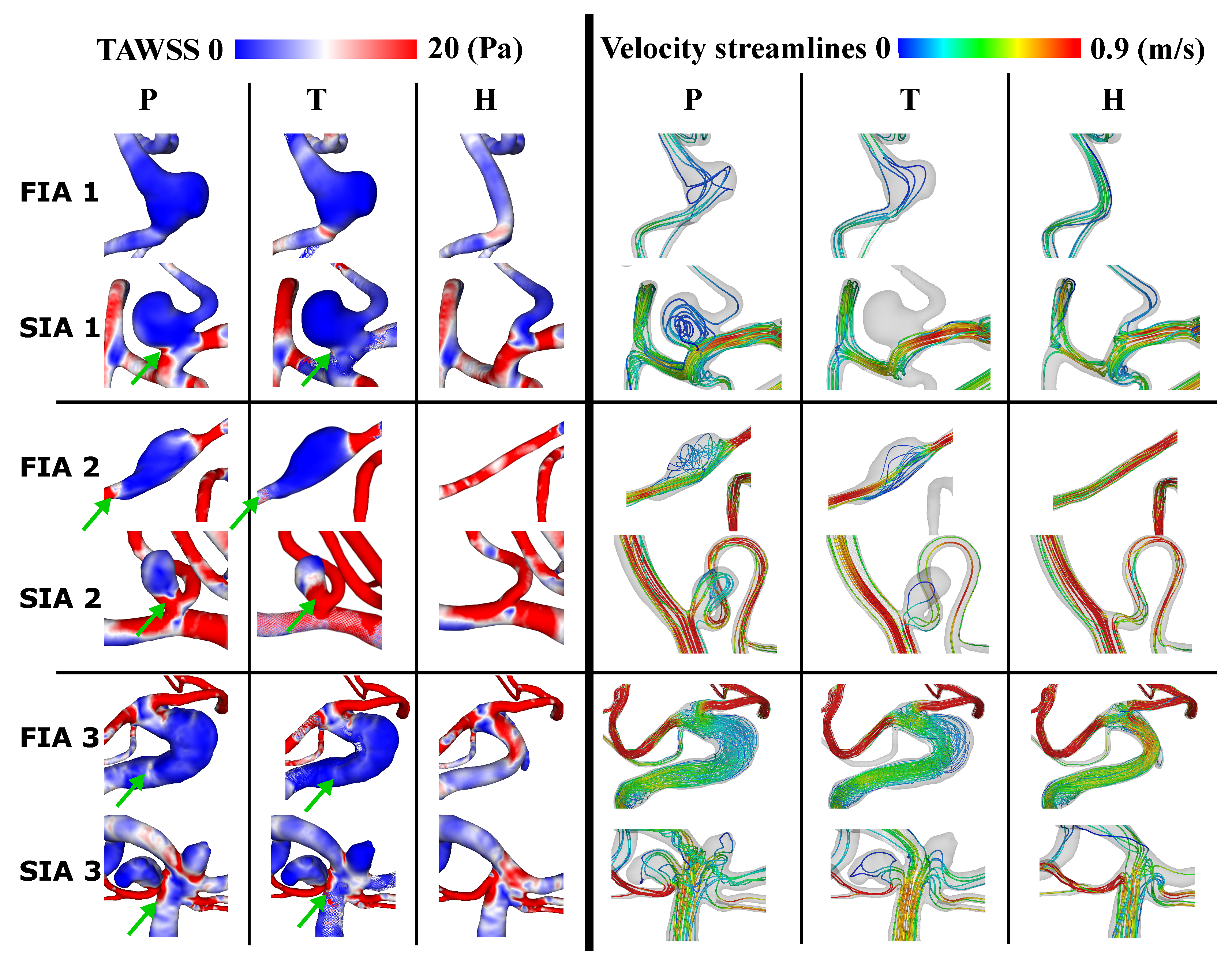
Figure 3 shows the resulting TAWSS on the vessel surfaces for the three FIA and SIA cases and each condition (P, T, H) on the left and the according streamlines colored with the mean v on the right. The TAWSS appears lower on the aneurysm dome after treatment for FIA and SIA compared to the pathological part. This applies especially for the aneurysms’ necks and borders (marked with green arrows in Figure 3). The healthy counterparts comprise higher TAWSS for both FIA and SIA when compared to T and P. Flow diversion is clearly visible from P to T when looking at the streamlines. Especially within the FIAs, from P to T streamlines are straightened and v seems higher. When considering H compared to P and T, v is highest. Within SIA 2/3 the streamlines still pass the aneurysm when comparing P to T and v is not noticeably increased. Within H of the SIA 2/3, v is higher than within P and T, as was also observed for the FIAs.
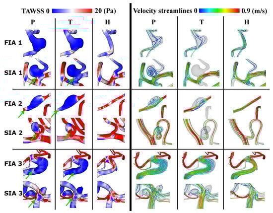
Figure 3.
Resulting TAWSS on aneurysm surface (left) and streamlines showing average velocity within vessel models (right) for cases 1–3 for pathological (P), treated (T) and healthy (H). Lower TAWSS at IA neck and border within T than P is marked with a green arrow.
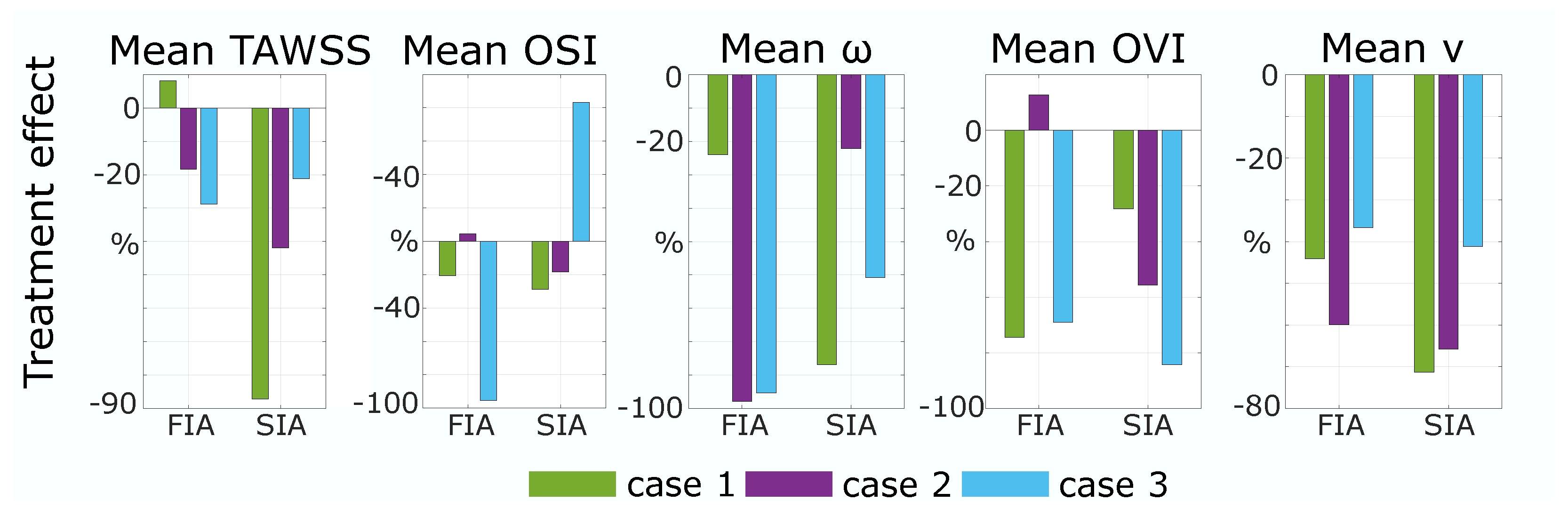
The quantitative results strengthen the assumption drawn from Figure 3. As shown in Figure 4 (left), the reduction in TAWSS from P to T is higher than 19% for FIA 1 and 2. For SIAs, the TE of TAWSS is higher than 20% for all cases and, compared to FIAs, SIA 1 and 2 present higher values than FIA 1 and 2. OSI is crucially reduced by treatment of FIA 1/3 (FIA 1: 20%, FIA 3: 95%) and slightly increased within FIA 2 (5%). Concerning SIAs, OSI is reduced for SIA 1/2 (SIA 1: 20%, SIA 2: 30%); a crucial increase of 80% appears within SIA 3. For the quantitative results of the mean values of v, and OVI the temporally and spatially averaged metrics are shown for each case 1–3 in Figure 4 on the right. The was reduced by treatment for all cases and an equal impact was presented for SIA and FIA treatment. Still, results for FIA 2/3 show a higher mean reduction (FIA 2: 95%, FIA 3: 97%) with treatment than for SIA 2/3 (SIA 2: 22%, SIA 3: 61%). Concerning OVI, a reduction was detectable for all cases (≥27%) despite FIA 2 (+13%). With treatment the mean v is reduced drastically and similar for SIAs and FIAs, being slightly higher (5–30%) for SIAs.

Figure 4.
Resulting Treatment Effect: The change in metrics for cases 1–3 from pathological to treated of TAWSS and OSI on the aneurysm surface and of mean , mean OVI, and mean velocity (v) inside aneurysm sac.
The resulting EL for each case and condition is shown in Table 2. Looking at the pathological cases, EL is lowest for case 1, higher for case 2, and highest for case 3. This applies for FIA and SIA. Within FIA 1 and FIA 2 the EL is higher for the healthy than for the pathological cases; this is not the case for FIA 3, where EL is lower for the healthy case. Also, within SIA 1–3 EL is lower within the healthy cases than within the pathological ones. Concerning the treated IAs, EL is higher than healthy and pathological for all SIAs and for FIA 2. For FIA 1/3, EL is lowest within the treated version.
Table 2.
Resulting Energy Loss for each case and condition in Watt (W).
4. Discussion
While the investigation of IAs increased in recent years, especially due to improving medical imaging technologies and numerical simulations, the focus mostly lies on saccular shapes. Deploying FDS as a minimally-invasive endovascular treatment of SIAs was established and the reduction of the flow into the SIA has been presented in many studies [6,41,42]. Fusiform-shaped IAs in the cerebrovascular circulation are as of yet not well studied, and knowledge about the flow field and treatment effect is still low [20]. The aim of this study was to analyze FIAs in comparison to SIAs focusing on the treatment with FDS.
4.1. Morphology and Stent
The virtual stent analysis shows an increased deployed diameter past the given diameter for all FIAs. The mean stent expansions follow a similar trend for all cases with stronger values across the entire FIA than the corresponding saccular ones. The ability of the stent to freely expand circumferentially in the FIAs lends itself to this greater max and mean expansion. Since the stent area and length for FIAs are substantially larger (see Table 1) one outcome of over-expansion, even just within the IA, is foreshortening. Another, even greater concern is that the porosity increased and allowed a higher flow into the IA. This is visible in the qualitative and quantitative hemodynamic results (recall Figure 3 and Figure 4, which show, in general, a lower TE for FIA than SIA. Rhee et al. considered, that even though with decreasing porosity the intra-aneurysmal flow was positively affected; however, this effect was not significant [43]. Compared to typically shaped FIAs, the stent expansion was lower [21].
4.2. Wall-Related Parameters
As Rhee et al. found, FDS have a higher impact on WSS reduction within SIAs than FIAs [43]; within this study, a higher impact onto TAWSS within SIAs than FIAs was found as well. Nevertheless, the non-typical shape of the investigated FIAs lead to a better TE in general when comparing to the literature [43]. FIA 1 has an increase of WSS which appears to be a direct result of the flow diverted away from the treated vessel branch, and less from the aneurysmal apex itself. Moreover, FIA 1 has featured the highest stent expansion. However, because of the nature of FIAs, this change in TAWSS to the treated vessel/aneurysmal sac can be important to the FIA growth [44]. FIA 2 experiences an increase in OSI. This post-treatment increase in oscillation appears in a low-velocity region and also seems to coincide with a high-OSI surface in the treated case. This can be related to the findings of Takehara et al. [45], who found higher OSI in regions with low velocity and decreased WSS when analyzing aortic hemodynamics with four-dimensional flow magnetic resonance imaging. SIA 3 also showed a strong increase in OSI which occurs at the apex of the IA dome where the already low WSS may be changing directions based on minor deviations in the flow throughout the cardiac cycle (recall the streamlines in Figure 3) [23]. OSI showing variable increase or decrease when applying FDS in FIAs agrees with Lv et al. [24].
4.3. Flow-Related Parameters
Concerning the hemodynamic results, treated IAs generally see equal reductions of the velocity for FIAs and SIAs (recall Figure 3 and Figure 4). Concerning SIA reduction, this was already presented in the literature [2]. The streamlines illustrate that the flow is redirected through the parent vessel part by FDS in SIAs, which is in accordance with Sindeev et al. [23]. This might be affected by the non-typical shape of the non-typical circumferential FIAs as well. This shows that the circumferential shape has to be taken into account additionally when defining the treatment method based on the aneurysmal geometry. The overall higher reduction in within FIAs, leads to the assumption, that with FDS, flow structures were straightened as well, which can also be derived from Figure 3. Lv et al. [24], who investigated multiple treatment in FIAs, stated that with FDS the vortex formation inside the IA shifts from the wall to the vessel center, which agrees with the findings in this study: OVI and are decreased with treatment, leading to the fact that vortex formation is decreased as well. Interestingly, FIA 2 has one of the largest reductions in , but shows an increase in OVI. Again, this might be related to the reduced velocity, since fluctuations of lower velocities within the IA lead to an increase in OVI. Furthermore, this could be due to the non-typical shape of the FIA as mentioned regarding the wall parameters.
4.4. Energy Loss
Concerning the pathological to healthy comparison of the EL, lower EL occurs within FIA and higher EL within SIA compared to the healthy counterpart. In this study, the treatment increases the EL drastically for all SIAs and decreases the EL in FIA 1/3. Chong et al. found out that reduced EL has been correlated with favorable outcome of stent-treated endovascular therapies [46]. This indicates that due to treatment, the flow energy is converted into fluctuations within the underlying cases. Looking at FIA 1/3, the reduction indicates a favorable outcome of the treatment. However, for FIA 2 the treatment increases the EL. The lower EL within untreated pathological FIAs, is an interesting, but doubtful outcome. Since compared to a previous study, the resulting EL values for SIAs are higher for FIA/SIA 2/3 (≈50%) [40], the EL results may not give crucial hints on successful treatment effect for the underlying cases.
4.5. Limitations and Future Work
First, due to a lack of information, the numerical simulations underlying assumptions (no patient-specific inflow curves, blood assumed Newtonian, rigid walls) and IA treatment could not be visualized in vivo. Nevertheless, within the literature, validation of numerical simulations is performed in several studies and the use of CFD is well-established in patient-specific blood flow analysis [32,37]. Second, only a small number of cases was analyzed. Since FIAs occur only with a prevalence of approx. 3% of all IAs [15] and are rarely captured by medical imaging so far, this is nevertheless a progress in their investigation [20,47]. Third, regarding the virtual stenting and vessel reconstruction only one FDS version was virtually placed into the IAs neglecting the analysis of differences in porosity and no proof of the healthy vessel was available. This could help in finding reasons for less TAWSS reduction and possibilities for higher overall flow reduction. Fourth, the deployment of FDS in SIAs is not the best possible treatment and only virtually applied in this study to preserve the comparable basis of the treatment outcome. Future work will therefore include the comparison of different treatment option in SIAs and FIAs. Moreover, variation in stent porosity and a multiple stent analysis to extend the knowledge about the impact of FDS onto FIAs will be considered. Moreover, to strengthen these findings, a higher number of cases should be analyzed; in vitro as well as in vivo validation is required. Despite these limitations, the compatibility of FDS in non-typically shaped FIAs is presented within this study. The comparable reduction in velocity from FDS within FIAs and SIAs is shown.
5. Conclusions
FDS within FIAs show higher expansion and therefore a possible reduction in porosity when compared to SIA implantation. Nevertheless, FDS affect FIAs and SIAs equally when considering flow reduction, namely velocity and vorticity. Still, TAWSS and OVI reduction is higher for SIAs. FIAs with a non-typical circularly shape show a treatment outcome closer to the SIA treatment outcome for specific parameters, which should be taken into account when deciding on the treatment method of an FIA. Still, no significant statement could be derived from the low case count, which will be increased in future work to reach a significant outcome. Moreover, the analysis could be extended by adding multiple (double or triple) FDS to find out if this leads to stronger TAWSS reduction in FIAs.
Author Contributions
Conceptualization, J.K., L.M.M.M. and P.B.; methodology, J.K., L.M.M.M. and S.S.; software, J.K. and L.M.M.M.; validation, J.K., L.M.M.M. and D.B.; formal analysis, J.K. and L.M.M.M.; investigation, J.K.; resources, A.A. and P.B.; data curation, S.S., D.B. and P.B.; writing—original draft preparation, J.K. and L.M.M.M.; writing—review and editing, J.K., S.S., L.M.M.M., A.A. and P.B.; visualization, J.K.; supervision, P.B. and A.A.; project administration, J.K.; funding acquisition, P.B., S.S., L.M.M.M. and A.A. All authors have read and agreed to the published version of the manuscript.
Funding
The authors gratefully acknowledge financial support for this publication by the Fulbright U.S. Student Program, which is sponsored by the U.S. Department of State and the German-American Fulbright Commission, by the German Federal Ministry of Education and Research within the Research Campus STIMULATE (grant no. 13GW0473A) and by the German Research Foundation (SPP2311, project number: 465189657).
Institutional Review Board Statement
Not applicable.
Informed Consent Statement
Not applicable.
Data Availability Statement
Data are available under reasonable request.
Acknowledgments
Thank you to Mike Levitt of the Departments of Neurological Surgery, University of Washington, Seattle, WA for your advice.
Conflicts of Interest
The authors declare no conflicts of interest.
Abbreviations
The following abbreviations are used in this manuscript:
| A | Surface Area |
| AR | Aspect Ratio |
| BA | Basilar Artery |
| CFD | Computational Fluid Dynamics |
| DSA | Digital Subtraction Angiography |
| E | Energy |
| EL | Energy Loss |
| FDS | Flow Diverting Stent |
| FIA | Fusiform Intracranial Aneurysm |
| H | Healthy |
| IA | Intracranial Aneurysm |
| MCA | Middle Cerebral Artery |
| VA | Vertebral Artery |
| OVI | Oscillatory Velocity Index |
| OSI | Oscillatory Shear Index |
| P | Pathological |
| p | Pressure |
| SIA | Saccular Intracranial Aneurysm |
| T | Treated |
| TAWSS | Time Averaged Wall Shear Stress |
| Cardiac Cycle Length | |
| v | velocity |
| W | Watt |
| WSS | Wall Shear Stress |
| Fluid Density | |
| Vorticity |
References
- Boussel, L.; Rayz, V.; McCulloch, C.; Martin, A.; Acevedo-Bolton, G.; Lawton, M.; Higashida, R.; Smith, W.S.; Young, W.L.; Saloner, D. Aneurysm growth occurs at region of low wall shear stress: Patient-specific correlation of hemodynamics and growth in a longitudinal study. Stroke 2008, 39, 2997–3002. [Google Scholar] [CrossRef]
- Seibert, B.; Tummala, R.P.; Chow, R.; Faridar, A.; Mousavi, S.A.; Divani, A.A. Intracranial aneurysms: Review of current treatment options and outcomes. Front. Neurol. 2011, 2, 45. [Google Scholar] [CrossRef] [PubMed]
- Zhang, Y.; Jing, L.; Zhang, Y.; Liu, J.; Yang, X. Low wall shear stress is associated with the rupture of intracranial aneurysm with known rupture point: Case report and literature review. BMC Neurol. 2016, 16, 231. [Google Scholar] [CrossRef]
- Xiang, J.; Natarajan, S.K.; Tremmel, M.; Ma, D.; Mocco, J.; Hopkins, L.N.; Siddiqui, A.H.; Levy, E.I.; Meng, H. Hemodynamic-morphologic discriminants for intracranial aneurysm rupture. Stroke 2011, 42, 144–152. [Google Scholar] [CrossRef]
- Al-Mufti, F.; Cohen, E.R.; Amuluru, K.; Patel, V.; El-Ghanem, M.; Nuoman, R.; Majmundar, N.; Dangayach, N.S.; Meyers, P.M. Bailout Strategies and Complications Associated with the Use of Flow-Diverting Stents for Treating Intracranial Aneurysms. Interv. Neurol. 2020, 8, 38–54. [Google Scholar] [CrossRef]
- Salem, M.M.; Elfil, M.; Aboutaleb, P.E.; Dmytriw, A.A.; Thomas, A.J.; Hassan, A.E.; Mascitelli, J.R.; Kan, P.; Jankowitz, B.T.; Burkhardt, J.K. National Survey on Flow-Diverting Stents for Intracranial Aneurysms in the United States. World Neurosurg. 2022, 166, e958–e967. [Google Scholar] [CrossRef]
- Diestro, J.D.B.; Adeeb, N.; Dibas, M.; Boisseau, W.; Harker, P.; Brinjikji, W.; Xiang, S.; Joyce, E.; Shapiro, M.; Raz, E.; et al. Flow Diversion for Middle Cerebral Artery Aneurysms: An International Cohort Study. Neurosurgery 2021, 89, 1112–1121. [Google Scholar] [CrossRef]
- Pierot, L.; Wakhloo, A.K. Endovascular treatment of intracranial aneurysms: Current status. Stroke 2013, 44, 2046–2054. [Google Scholar] [CrossRef]
- Briganti, F.; Leone, G.; Marseglia, M.; Mariniello, G.; Caranci, F.; Brunetti, A.; Maiuri, F. Endovascular treatment of cerebral aneurysms using flow-diverter devices: A systematic review. Neuroradiol. J. 2015, 28, 365–375. [Google Scholar] [CrossRef]
- Echiverri, H.C.; Rubino, F.A.; Gupta, S.R.; Gujrati, M. Fusiform aneurysm of the vertebrobasilar arterial system. Stroke 1989, 20, 1741–1747. [Google Scholar] [CrossRef] [PubMed]
- Peeters, S.M.; Colby, G.P.; Kim, W.J.; Bae, W.I.; Sparks, H.; Reitz, K.; Tateshima, S.; Jahan, R.; Szeder, V.; Nour, M.; et al. Proximal Internal Carotid Artery Occlusion and Extracranial-Intracranial Bypass for Treatment of Fusiform and Giant Internal Carotid Artery Aneurysms. World Neurosurg. 2023, 180, e494–e505. [Google Scholar] [CrossRef]
- Serrone, J.C.; Gozal, Y.M.; Grossman, A.W.; Andaluz, N.; Abruzzo, T.; Zuccarello, M.; Ringer, A. Vertebrobasilar Fusiform Aneurysms. Neurosurg. Clin. N. Am. 2014, 25, 471–484. [Google Scholar] [CrossRef]
- Day, A.L.; Gaposchkin, C.G.; Yu, C.J.; Rivet, D.J.; Dacey, R.G. Spontaneous fusiform middle cerebral artery aneurysms: Characteristics and a proposed mechanism of formation. J. Neurosurg. 2003, 99, 228–240. [Google Scholar] [CrossRef]
- al Yamany, M.; Ross, I.B. Giant fusiform aneurysm of the middle cerebral artery: Successful Hunterian ligation without distal bypass. Br. J. Neurosurg. 1998, 12, 572–575. [Google Scholar] [CrossRef] [PubMed]
- Park, S.H.; Yim, M.B.; Lee, C.Y.; Kim, E.; Son, E.I. Intracranial Fusiform Aneurysms: It’s Pathogenesis, Clinical Characteristics and Managements. J. Korean Neurosurg. Soc. 2008, 44, 116–123. [Google Scholar] [CrossRef]
- Städt, M.; Holtmannspötter, M.; Eff, F.; Voit-Höhne, H. Non-visualizable stent-occlusion after treatment of a fusiform PCA-aneurysm–a case report. Radiol. Case Rep. 2021, 16, 2573–2578. [Google Scholar] [CrossRef]
- Elbaroody, M.; Fiki, A.E.; Eldabaa, K.A.; Ghaneim, M.E.; Gabr, M. Multiple clips reconstruction for giant fusiform Middle Cerebral Artery aneurysm. Interdiscip. Neurosurg. 2022, 29, 101538. [Google Scholar] [CrossRef]
- Telles, J.P.M.; Solla, D.J.F.; Yamaki, V.N.; Rabelo, N.N.; da Silva, S.A.; Caldas, J.G.P.; Teixeira, M.J.; Junior, J.R.; Figueiredo, E.G. Comparison of surgical and endovascular treatments for fusiform intracranial aneurysms: Systematic review and individual patient data meta-analysis. Neurosurg. Rev. 2020, 44, 2405–2414. [Google Scholar] [CrossRef]
- Kim, J.; Hwang, G.; Kim, B.T.; Park, S.Q.; Oh, J.S.; Ban, S.P.; Kwon, O.K.; Chung, J. Safety and Efficacy of Flow Diverter Therapy for Unruptured Intracranial Aneurysm Compared to Traditional Endovascular Strategy: A Multi-Center, Randomized, Open-Label Trial. J. Korean Neurosurg. Soc. 2022, 65, 772–778. [Google Scholar] [CrossRef] [PubMed]
- Saalfeld, S.; Stahl, J.; Korte, J.; Miller Marsh, L.M.; Preim, B.; Beuing, O.; Cherednychenko, Y.; Behme, D.; Berg, P. Can Endovascular Treatment of Fusiform Intracranial Aneurysms Restore the Healthy Hemodynamic Environment?–A Virtual Pilot Study. Front. Neurol. 2022, 12, 771694. [Google Scholar] [CrossRef]
- Barletta, E.A.; Ricci, R.L.; Di Silva, R.G.; Gaspar, R.H.M.L.; Araújo, J.F.M.; Neves, M.W.F.; de Aquino, J.L.B.; Barba Belsuzarri, T.A. Fusiform aneurysms: A review from its pathogenesis to treatment options. Surg. Neurol. Int. 2018, 9, 189. [Google Scholar] [CrossRef]
- Reorowicz, P.; Tyfa, Z.; Obidowski, D.; Wiśniewski, K.; Stefańczyk, L.; Jóźwik, K.; Levy, M.L. Blood flow through the fusiform aneurysm treated with the Flow Diverter stent—Numerical investigations. Biocybern. Biomed. Eng. 2022, 42, 375–390. [Google Scholar] [CrossRef]
- Sindeev, S.; Kirschke, J.S.; Prothmann, S.; Frolov, S.; Liepsch, D.; Berg, P.; Zimmer, C.; Friedrich, B. Evaluation of flow changes after telescopic stenting of a giant fusiform aneurysm of the vertebrobasilar junction. Biomed. Eng. Online 2019, 18, 82. [Google Scholar] [CrossRef] [PubMed]
- Lv, N.; Cao, W.; Larrabide, I.; Karmonik, C.; Zhu, D.; Liu, J.; Huang, Q.; Fang, Y. Hemodynamic Changes Caused by Multiple Stenting in Vertebral Artery Fusiform Aneurysms: A Patient-Specific Computational Fluid Dynamics Study. AJNR Am. J. Neuroradiol. 2018, 39, 118–122. [Google Scholar] [CrossRef]
- Griffin, A.; Lerner, E.; Zuchowski, A.; Zomorodi, A.; Gonzalez, L.F.; Hauck, E.F. Flow diversion of fusiform intracranial aneurysms. Neurosurg. Rev. 2020, 44, 1471–1478. [Google Scholar] [CrossRef]
- Lyu, M.; Ventikos, Y.; Peach, T.W.; Makalanda, L.; Bhogal, P. Virtual Flow-T Stenting for Two Patient-Specific Bifurcation Aneurysms. Front. Neurol. 2021, 12, 726980. [Google Scholar] [CrossRef]
- Zhong, L.; Zhang, J.M.; Su, B.; Tan, R.S.; Allen, J.C.; Kassab, G.S. Application of Patient-Specific Computational Fluid Dynamics in Coronary and Intra-Cardiac Flow Simulations: Challenges and Opportunities. Front. Physiol. 2018, 9, 742. [Google Scholar] [CrossRef] [PubMed]
- Jiang, Y.; Lu, G.; Ge, L.; Zou, R.; Li, G.; Wan, H.; Leng, X.; Xiang, J.; Zhang, X. Hemodynamic Comparison of Treatment Strategies for Intracranial Vertebral Artery Fusiform Aneurysms. Front. Neurol. 2022, 13, 927135. [Google Scholar] [CrossRef]
- Findlay, J.; Hao, C.; Emery, D. Non-Atherosclerotic Fusiform Cerebral Aneurysms. Can. J. Neurol. Sci. Le J. Can. Des Sci. Neurol. 2002, 29, 41–48. [Google Scholar] [CrossRef]
- Janiga, G.; Daróczy, L.; Berg, P.; Thévenin, D.; Skalej, M.; Beuing, O. An automatic CFD-based flow diverter optimization principle for patient-specific intracranial aneurysms. J. Biomech. 2015, 48, 3846–3852. [Google Scholar] [CrossRef]
- Janiga, G.; Berg, P.; Beuing, O.; Neugebauer, M.; Gasteiger, R.; Preim, B.; Rose, G.; Skalej, M.; Thévenin, D. Recommendations for accurate numerical blood flow simulations of stented intracranial aneurysms. Biomed. Tech. Eng. 2013, 58, 303–314. [Google Scholar] [CrossRef] [PubMed]
- Berg, P.; Stucht, D.; Janiga, G.; Beuing, O.; Speck, O.; Thévenin, D. Cerebral blood flow in a healthy Circle of Willis and two intracranial aneurysms: Computational fluid dynamics versus four-dimensional phase-contrast magnetic resonance imaging. J. Biomech. Eng. 2014, 136, 041003. [Google Scholar] [CrossRef]
- Valen-Sendstad, K.; Piccinelli, M.; KrishnankuttyRema, R.; Steinman, D.A. Estimation of inlet flow rates for image-based aneurysm CFD models: Where and how to begin? Ann. Biomed. Eng. 2015, 43, 1422–1431. [Google Scholar] [CrossRef]
- Hodis, S.; Kargar, S.; Kallmes, D.; Dragomir-Daescu, D. Artery Length Sensitivity in Patient-Specific Cerebral Aneurysm Simulations. Am. J. Neuroradiol. 2014, 36, 737–743. [Google Scholar] [CrossRef] [PubMed]
- Saalfeld, S.; Voß, S.; Beuing, O.; Preim, B.; Berg, P. Flow-splitting-based computation of outlet boundary conditions for improved cerebrovascular simulation in multiple intracranial aneurysms. Int. J. Comput. Assist. Radiol. Surg. 2019, 14, 1805–1813. [Google Scholar] [CrossRef]
- Korte, J.; Voß, S.; Janiga, G.; Beuing, O.; Behme, D.; Saalfeld, S.; Berg, P. Is Accurate Lumen Segmentation More Important than Outlet Boundary Condition in Image-Based Blood Flow Simulations for Intracranial Aneurysms? Cardiovasc. Eng. Technol. 2023, 14, 617–630. [Google Scholar] [CrossRef] [PubMed]
- Cebral, J.R.; Mut, F.; Weir, J.; Putman, C.M. Association of hemodynamic characteristics and cerebral aneurysm rupture. AJNR Am. J. Neuroradiol. 2011, 32, 264–270. [Google Scholar] [CrossRef] [PubMed]
- Xiang, J.; Tutino, V.M.; Snyder, K.V.; Meng, H. CFD: Computational fluid dynamics or confounding factor dissemination? The role of hemodynamics in intracranial aneurysm rupture risk assessment. AJNR Am. J. Neuroradiol. 2014, 35, 1849–1857. [Google Scholar] [CrossRef]
- Tanioka, S.; Ishida, F.; Kishimoto, T.; Tsuji, M.; Tanaka, K.; Shimosaka, S.; Toyoda, M.; Kashiwagi, N.; Sano, T.; Suzuki, H. Quantification of hemodynamic irregularity using oscillatory velocity index in the associations with the rupture status of cerebral aneurysms. J. Neurointerv. Surg. 2019, 11, 614–617. [Google Scholar] [CrossRef]
- Hu, P.; Qian, Y.; Lee, C.J.; Zhang, H.Q.; Ling, F. The energy loss may predict rupture risks of anterior communicating aneurysms: A preliminary result. Int. J. Clin. Exp. Med. 2015, 8, 4128–4133. [Google Scholar]
- Guo, H.; Liu, J.F.; Li, C.H.; Wang, J.W.; Li, H.; Gao, B.L. Effects of stent-assisted coiling in comparison with flow diversion on intracranial aneurysms. Front. Neurol. 2022, 13, 937536. [Google Scholar] [CrossRef] [PubMed]
- Wang, C.; Tian, Z.; Liu, J.; Jing, L.; Paliwal, N.; Wang, S.; Zhang, Y.; Xiang, J.; Siddiqui, A.H.; Meng, H.; et al. Hemodynamic alterations after stent implantation in 15 cases of intracranial aneurysm. Acta Neurochir. 2016, 158, 811–819. [Google Scholar] [CrossRef] [PubMed]
- Rhee, K.; Han, M.H.; Cha, S.H. Changes of flow characteristics by stenting in aneurysm models: Influence of aneurysm geometry and stent porosity. Ann. Biomed. Eng. 2002, 30, 894–904. [Google Scholar] [CrossRef] [PubMed]
- Brunozzi, D.; Theiss, P.; Andrews, A.; Amin-Hanjani, S.; Charbel, F.T.; Alaraj, A. Correlation Between Laminar Wall Shear Stress and Growth of Unruptured Cerebral Aneurysms: In Vivo Assessment. World Neurosurg. 2019, 131, e599–e605. [Google Scholar] [CrossRef]
- Takehara, Y. Clinical Application of 4D Flow MR Imaging for the Abdominal Aorta. Magn. Reson. Med. Sci. MRMS Off. J. Jpn. Soc. Magn. Reson. Med. 2022, 21, 354–364. [Google Scholar] [CrossRef]
- Chong, W.; Zhang, Y.; Qian, Y.; Lai, L.; Parker, G.; Mitchell, K. Computational hemodynamics analysis of intracranial aneurysms treated with flow diverters: Correlation with clinical outcomes. AJNR Am. J. Neuroradiol. 2014, 35, 136–142. [Google Scholar] [CrossRef]
- Hayes, W.T.; Bernhardt, H.; Young, J.M. Fusiform arteriosclerotic aneurysm of the basilar artery. Five cases including two ruptures. Vasc. Surg. 1967, 1, 171–178. [Google Scholar] [CrossRef]
Disclaimer/Publisher’s Note: The statements, opinions and data contained in all publications are solely those of the individual author(s) and contributor(s) and not of MDPI and/or the editor(s). MDPI and/or the editor(s) disclaim responsibility for any injury to people or property resulting from any ideas, methods, instructions or products referred to in the content. |
© 2024 by the authors. Licensee MDPI, Basel, Switzerland. This article is an open access article distributed under the terms and conditions of the Creative Commons Attribution (CC BY) license (https://creativecommons.org/licenses/by/4.0/).