
Carbon Fiber Implants in Orthopaedic Oncology

 , and
, and 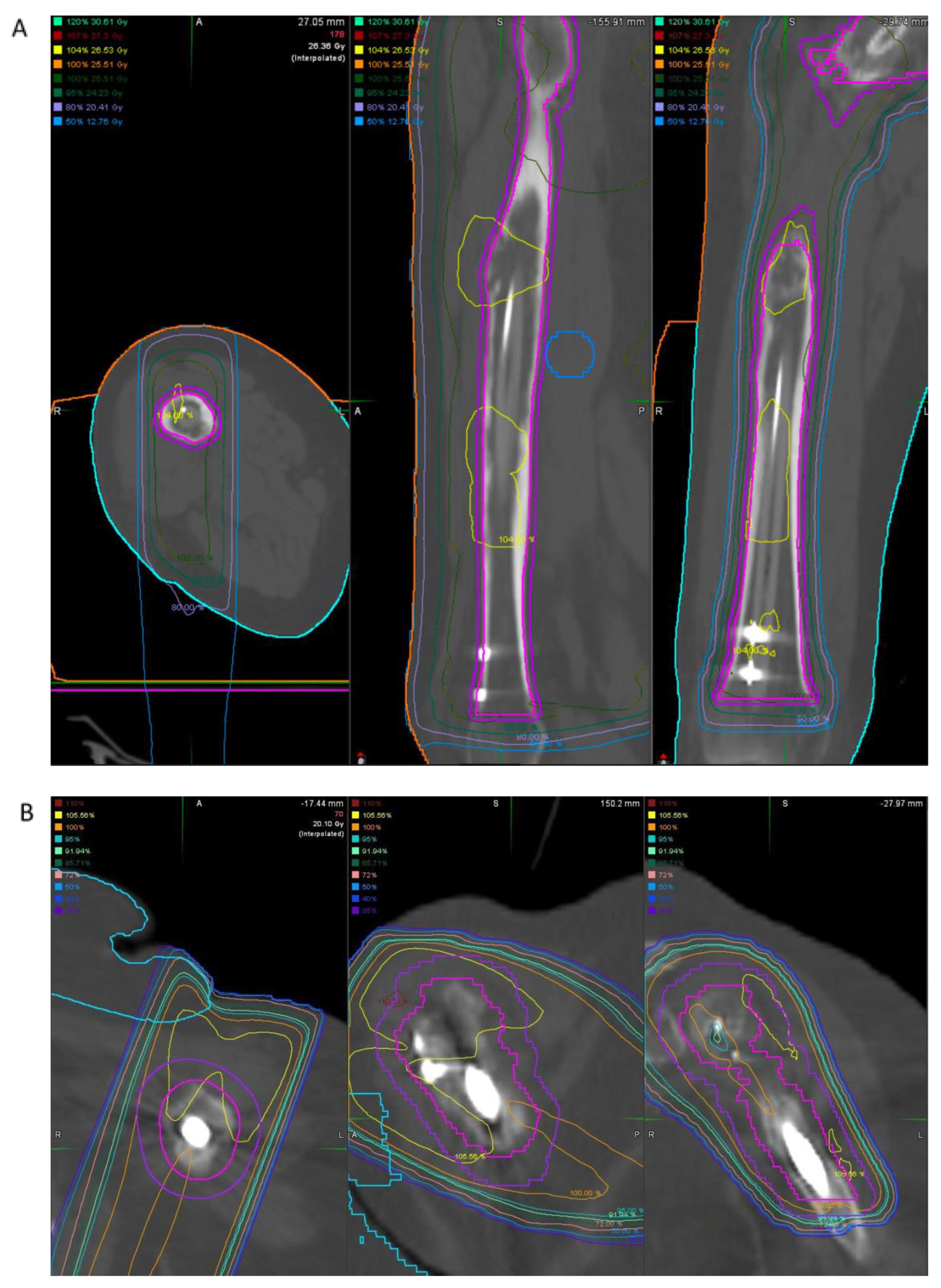
Abstract
1. Introduction
2. Material Properties and Benefits of Carbon Fiber
3. Carbon Fiber Implants in Orthopaedic Surgery
4. Case Examples
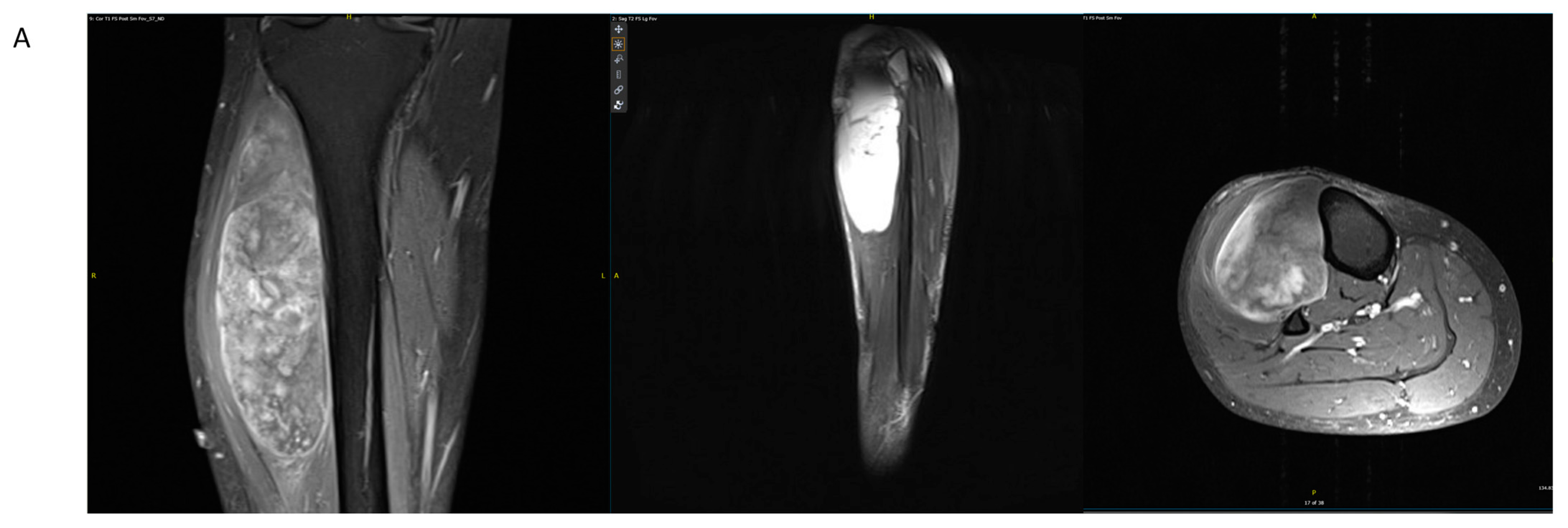
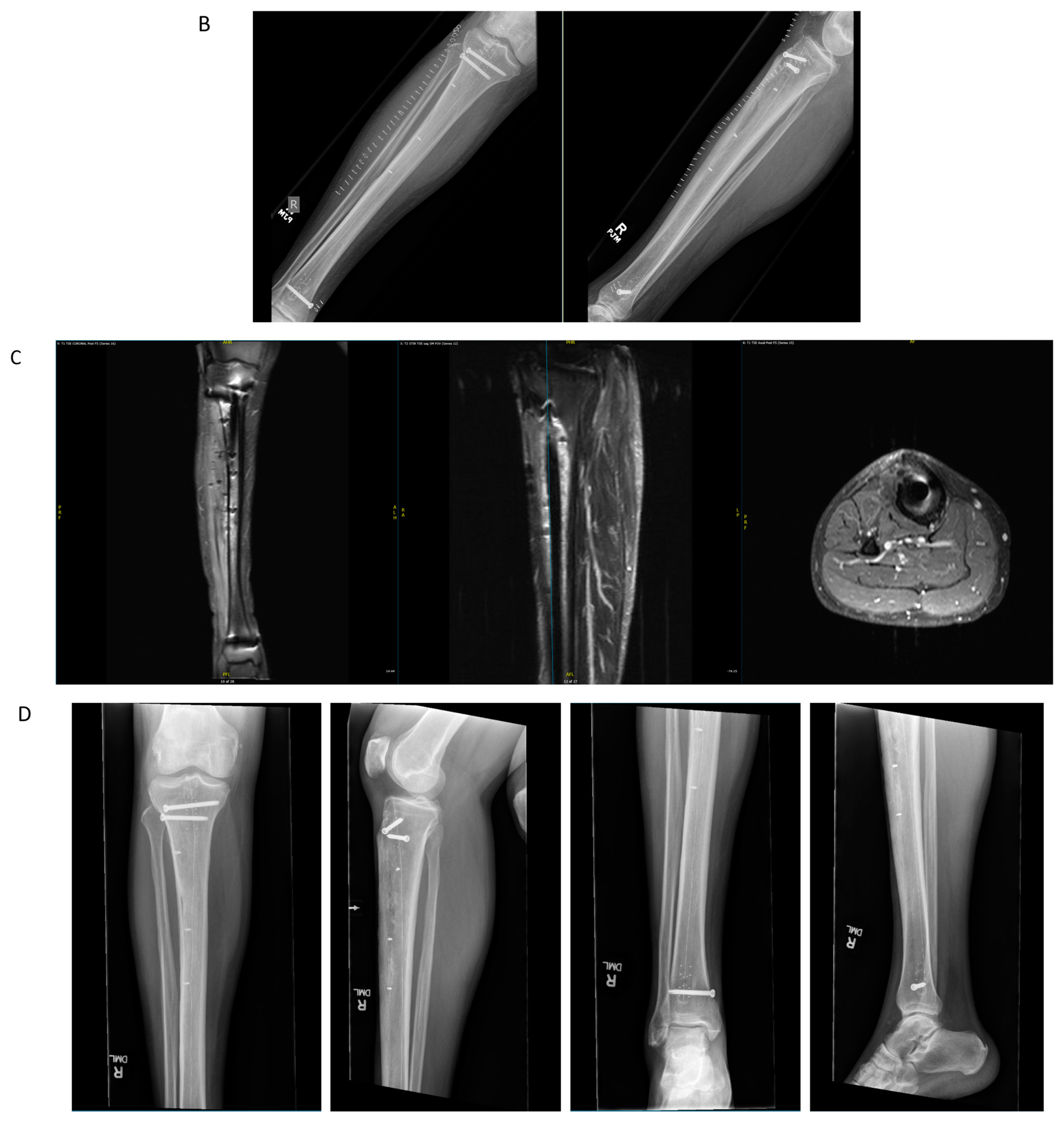
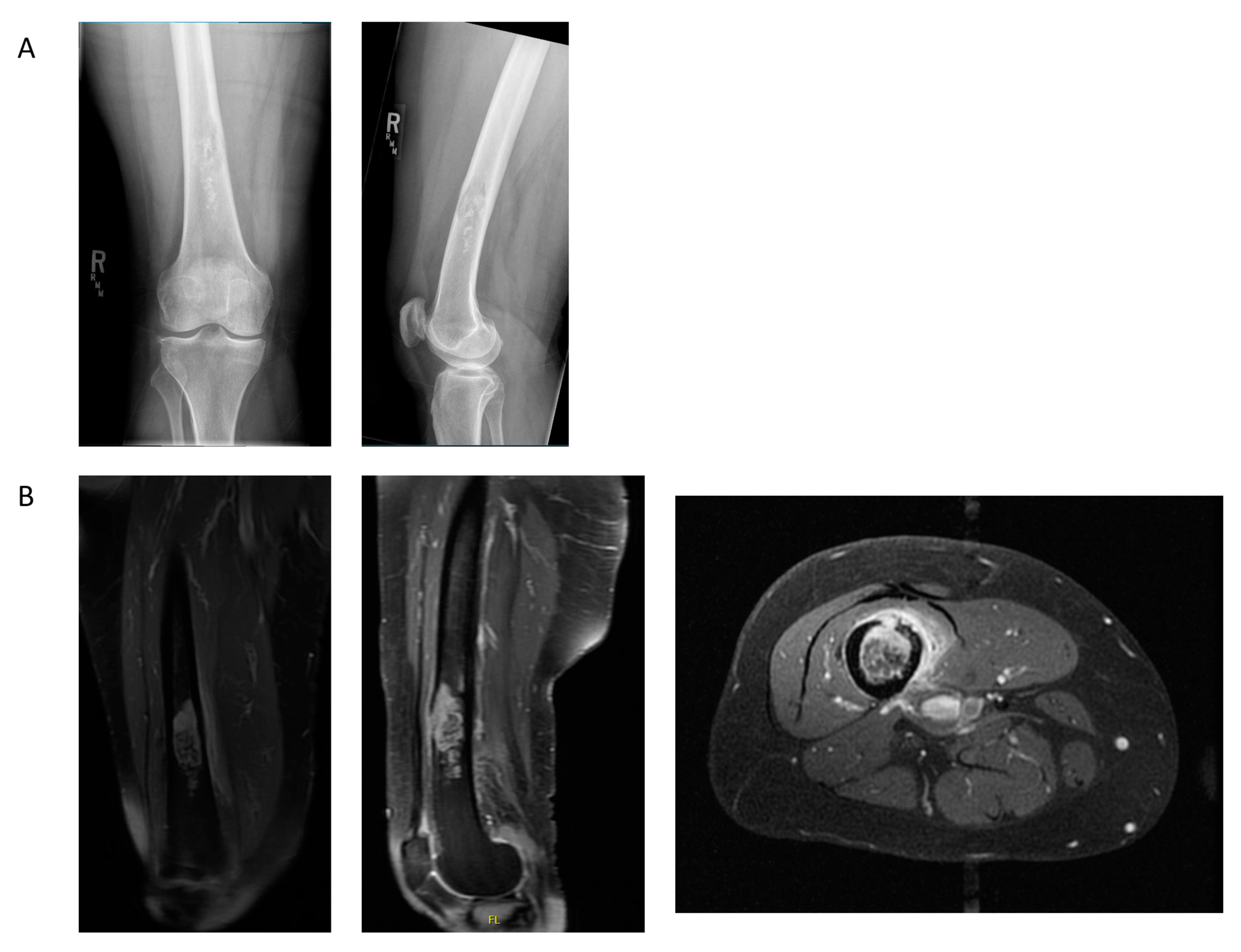
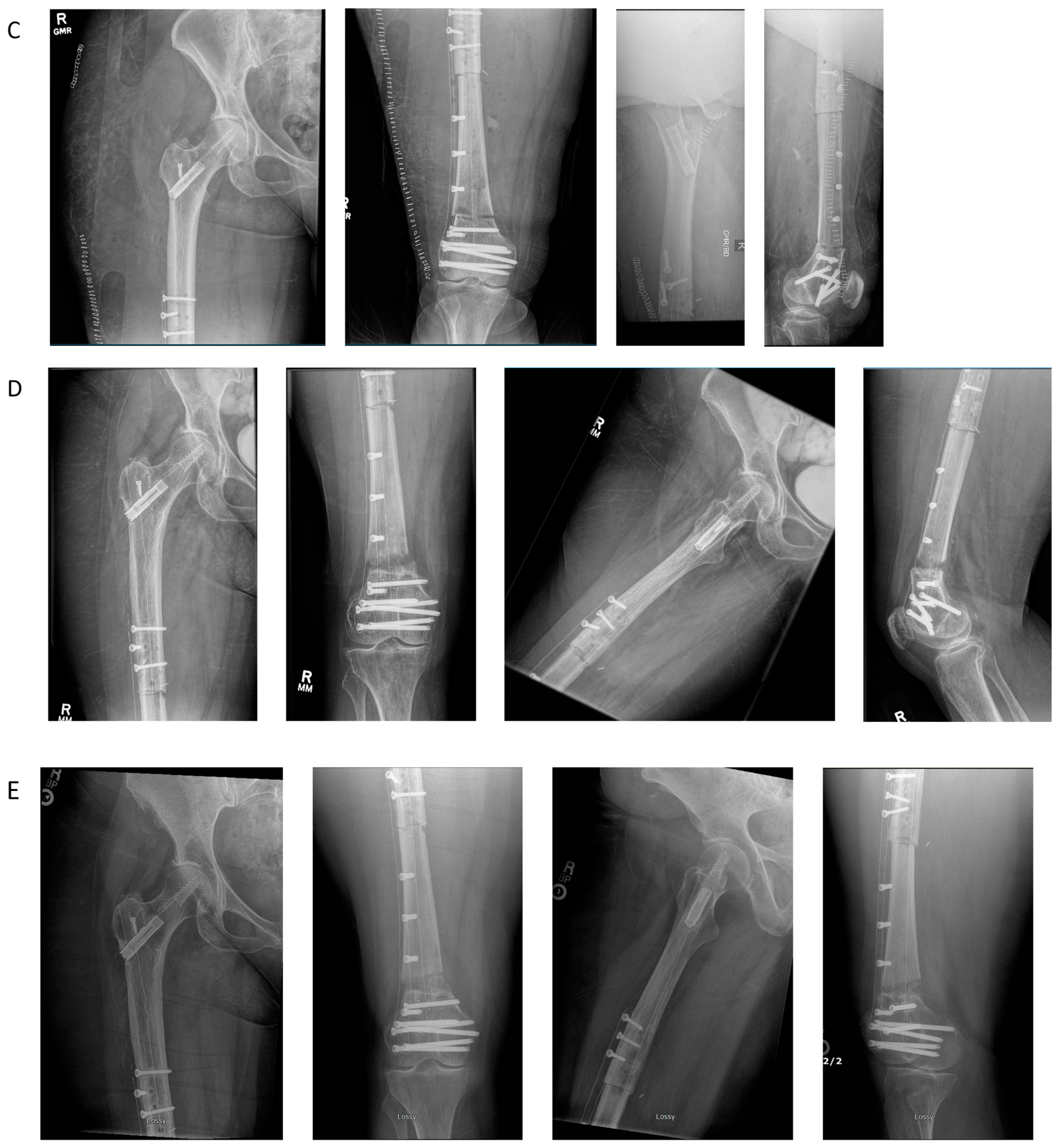
4.1. Case Example 1–Prophylactic Fixation via Intramedullary Nailing following Resection of Cortical Margin for Myxoid Liposarcoma Resection
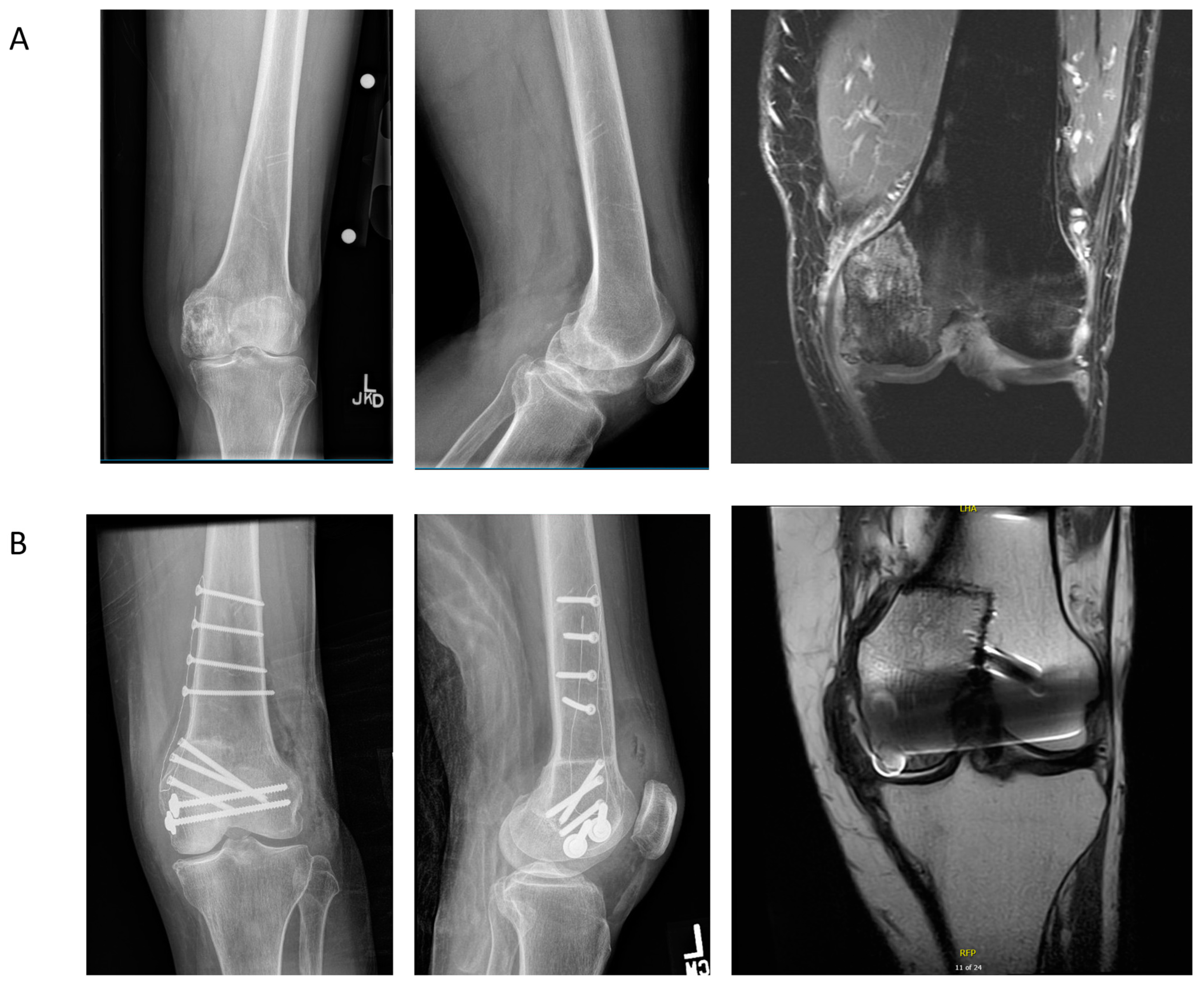
4.2. Case Example 2—Plate Fixation of Medial Femoral Condyle Osteoarticular Allograft following Medial Femoral Condyle Resection of Chondrosarcoma
4.3. Case Example 3—Plate and Intramedullary Nail Fixation of Allograft Reconstruction of Femoral Intercalary Resection of Chondrosarcoma
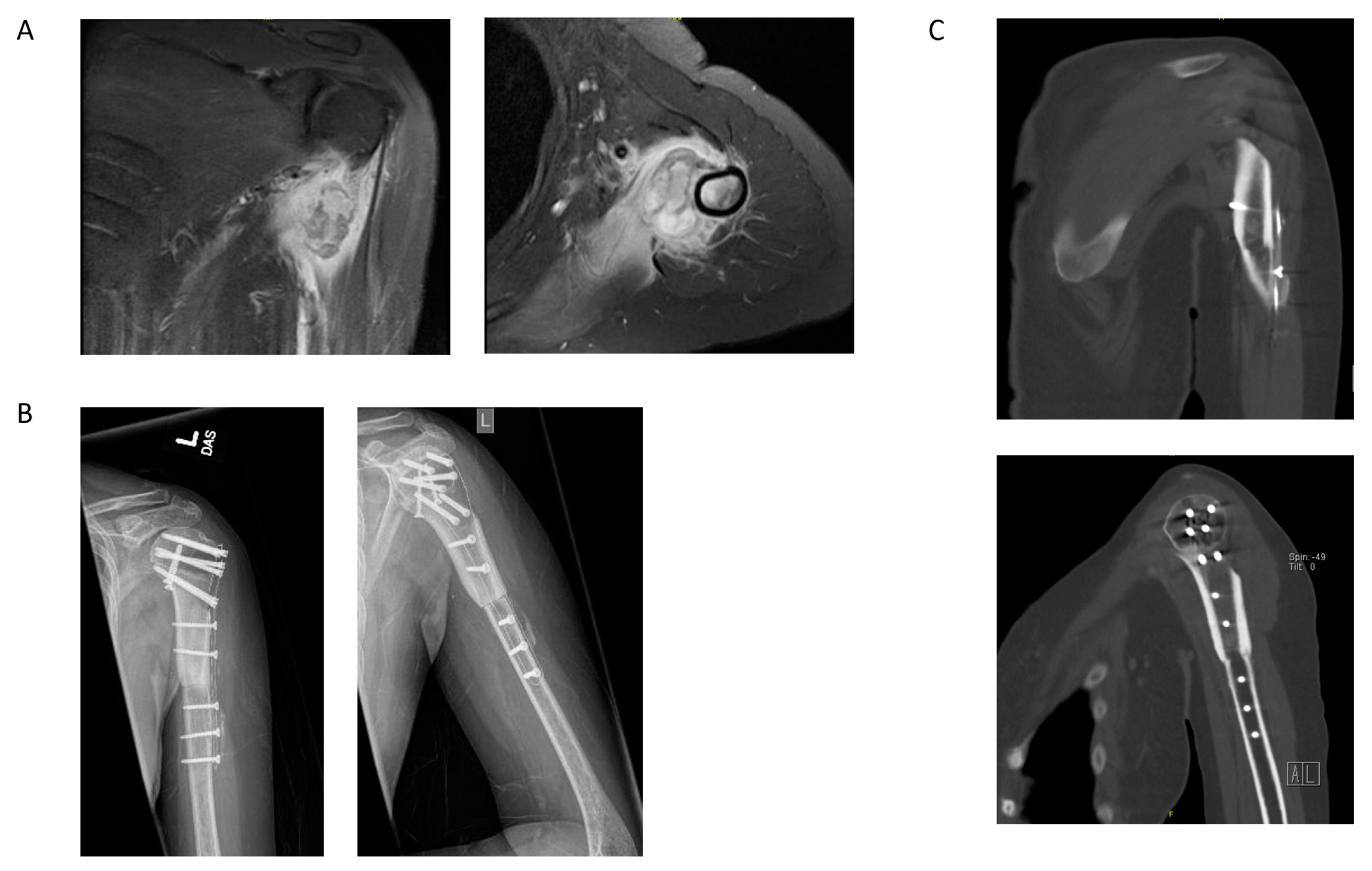
4.4. Case Example 4—Plate Fixation of Allograft Reconstruction of Proximal Humerus following Intercalary Resection of Parosteal Myositis Ossificans
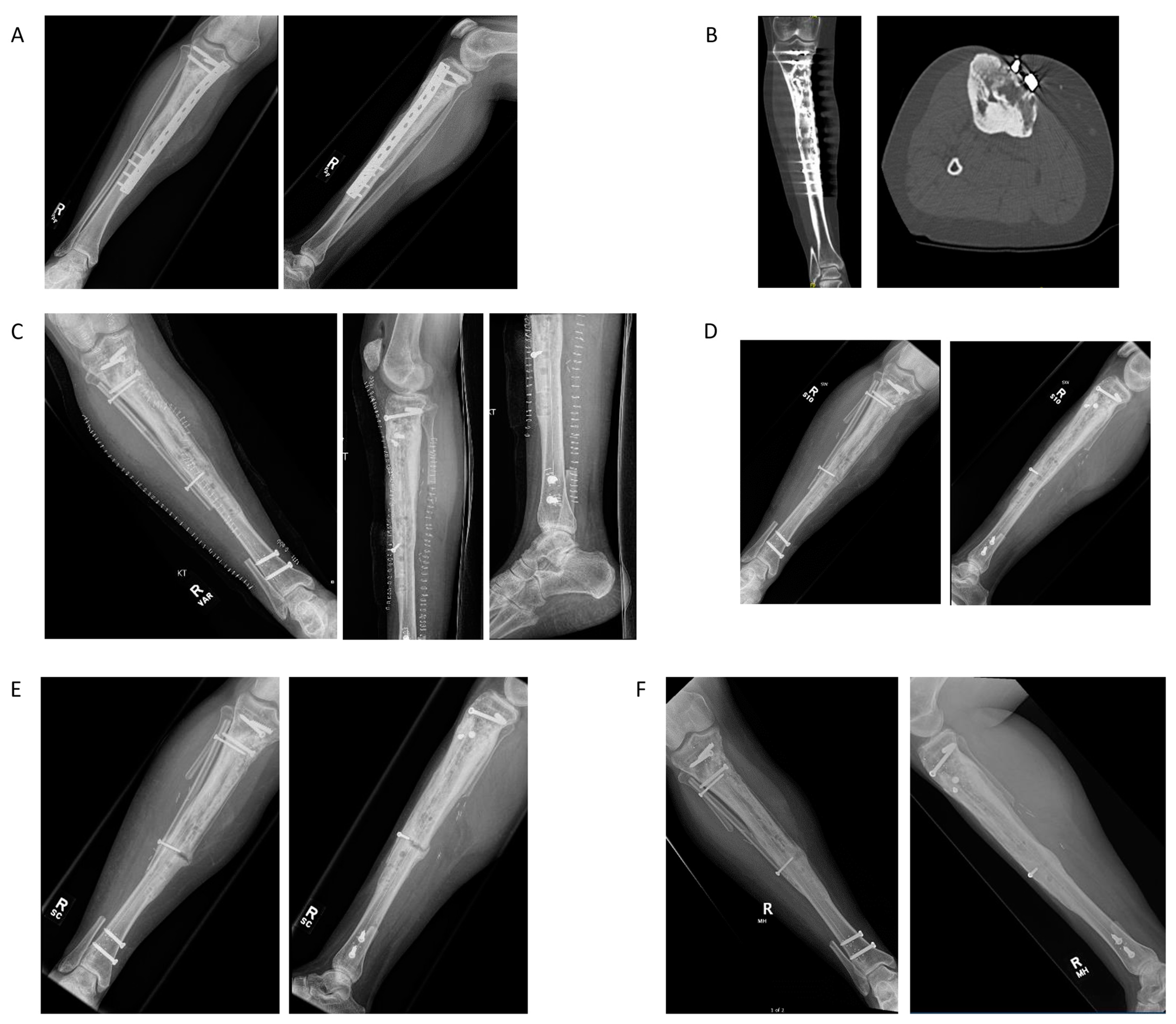
4.5. Case Example 5—Revision Plate and Nail Fixation with Fibular Autograft Augmentation of Prior Tibial Intercalary Allograft Failure
5. Considerations of Carbon Fiber in Orthopedic Oncology
6. Conclusions
Author Contributions
Funding
Institutional Review Board Statement
Informed Consent Statement
Data Availability Statement
Acknowledgments
Conflicts of Interest
References
- Hak, D.J.; Mauffrey, C.; Seligson, D.; Lindeque, B. Use of Carbon-Fiber-Reinforced Composite Implants in Orthopedic Surgery. Orthopedics 2014, 37, 825–830. [Google Scholar] [CrossRef] [PubMed]
- Su, W.; Swei, S.S.-M.; Zhu, G.G. Optimum Wing Shape Determination of Highly Flexible Morphing Aircraft for Improved Flight Performance. J. Aircr. 2016, 53, 1305–1316. [Google Scholar] [CrossRef] [PubMed]
- Ha, S.-W.; Kirch, M.; Birchler, F.; Eckert, K.-L.; Mayer, J.; Wintermantel, E.; Sittig, C.; Pfund-Klingenfuss, I.; Textor, M.; Spencer, N.; et al. Surface Activation of Polyetheretherketone (PEEK) and Formation of Calcium Phosphate Coatings by Precipitation. J. Mater. Sci. Mater. Med. 1997, 8, 683–690. [Google Scholar] [CrossRef]
- Katzer, A.; Marquardt, H.; Westendorf, J.; Wening, J.; von Foerster, G. Polyetheretherketone—Cytotoxicity and Mutagenicity in Vitro. Biomaterials 2002, 23, 1749–1759. [Google Scholar] [CrossRef]
- Jockisch, K.A.; Brown, S.A.; Bauer, T.W.; Merritt, K. Biological Response to Chopped-Carbon-Fiber-Reinforced Peek. J. Biomed. Mater. Res. 1992, 26, 133–146. [Google Scholar] [CrossRef] [PubMed]
- Golish, S.R.; Mihalko, W.M. Principles of Biomechanics and Biomaterials in Orthopaedic Surgery. J. Bone Jt. Surg. Am. 2011, 93, 207–212. [Google Scholar] [CrossRef] [PubMed]
- Brantigan, J.W.; Neidre, A. Achievement of Normal Sagittal Plane Alignment Using a Wedged Carbon Fiber Reinforced Polymer Fusion Cage in Treatment of Spondylolisthesis. Spine J. 2003, 3, 186–196. [Google Scholar] [CrossRef]
- Fujihara, K.; Huang, Z.-M.; Ramakrishna, S.; Satknanantham, K.; Hamada, H. Feasibility of Knitted Carbon/PEEK Composites for Orthopedic Bone Plates. Biomaterials 2004, 25, 3877–3885. [Google Scholar] [CrossRef]
- Dickinson, A.S.; Taylor, A.C.; Browne, M. The Influence of Acetabular Cup Material on Pelvis Cortex Surface Strains, Measured Using Digital Image Correlation. J. Biomech. 2012, 45, 719–723. [Google Scholar] [CrossRef]
- Maldonado, Z.M.; Seebeck, J.; Heller, M.O.W.; Brandt, D.; Hepp, P.; Lill, H.; Duda, G.N. Straining of the Intact and Fractured Proximal Humerus under Physiological-like Loading. J. Biomech. 2003, 36, 1865–1873. [Google Scholar] [CrossRef]
- Gardner, M.J.; Nork, S.E.; Huber, P.; Krieg, J.C. Less Rigid Stable Fracture Fixation in Osteoporotic Bone Using Locked Plates with near Cortical Slots. Injury 2010, 41, 652–656. [Google Scholar] [CrossRef]
- Katthagen, J.C.; Schwarze, M.; Warnhoff, M.; Voigt, C.; Hurschler, C.; Lill, H. Influence of Plate Material and Screw Design on Stiffness and Ultimate Load of Locked Plating in Osteoporotic Proximal Humeral Fractures. Injury 2016, 47, 617–624. [Google Scholar] [CrossRef]
- Schliemann, B.; Seifert, R.; Theisen, C.; Gehweiler, D.; Wähnert, D.; Schulze, M.; Raschke, M.J.; Weimann, A. PEEK versus Titanium Locking Plates for Proximal Humerus Fracture Fixation: A Comparative Biomechanical Study in Two- and Three-Part Fractures. Arch. Orthop. Trauma. Surg. 2017, 137, 63–71. [Google Scholar] [CrossRef]
- Li, C.S.; Vannabouathong, C.; Sprague, S.; Bhandari, M. The Use of Carbon-Fiber-Reinforced (CFR) PEEK Material in Orthopedic Implants: A Systematic Review. Clin. Med. Insights Arthritis Musculoskelet. Disord. 2015, 8, 33–45. [Google Scholar] [CrossRef]
- Miller, B.J.; Soni, E.E.C.; Gibbs, C.P.; Scarborough, M.T. Intramedullary Nails for Long Bone Metastases: Why Do They Fail? Orthopedics 2011, 34. [Google Scholar] [CrossRef]
- Steinberg, E.L.; Rath, E.; Shlaifer, A.; Chechik, O.; Maman, E.; Salai, M. Carbon Fiber Reinforced PEEK Optima—A Composite Material Biomechanical Properties and Wear/Debris Characteristics of CF-PEEK Composites for Orthopedic Trauma Implants. J. Mech. Behav. Biomed. Mater. 2013, 17, 221–228. [Google Scholar] [CrossRef]
- Brockett, C.L.; John, G.; Williams, S.; Jin, Z.; Isaac, G.H.; Fisher, J. Wear of Ceramic-on-Carbon Fiber-Reinforced Poly-Ether Ether Ketone Hip Replacements. J. Biomed. Mater. Res. Part B Appl. Biomater. 2012, 100B, 1459–1465. [Google Scholar] [CrossRef]
- Billi, F.; Benya, P.; Ebramzadeh, E.; Campbell, P.; Chan, F.; McKellop, H.A. Metal Wear Particles: What We Know, What We Do Not Know, and Why. SAS J. 2009, 3, 133–142. [Google Scholar] [CrossRef]
- Biant, L.C.; Bruce, W.J.M.; van der Wall, H.; Walsh, W.R. Infection or Allergy in the Painful Metal-on-Metal Total Hip Arthroplasty? J. Arthroplast. 2010, 25, 334.e11–334.e16. [Google Scholar] [CrossRef]
- Tayton, K.; Johnson-Nurse, C.; McKibbin, B.; Bradley, J.; Hastings, G. The Use of Semi-Rigid Carbon-Fibre-Reinforced Plastic Plates for Fixation of Human Fractures. Results of Preliminary Trials. J. Bone Jt. Surg. Br. 1982, 64, 105–111. [Google Scholar] [CrossRef]
- Zimel, M.N.; Hwang, S.; Riedel, E.R.; Healey, J.H. Carbon Fiber Intramedullary Nails Reduce Artifact in Postoperative Advanced Imaging. Skelet. Radiol. 2015, 44, 1317–1325. [Google Scholar] [CrossRef] [PubMed]
- Huang, J.Y.; Followill, D.S.; Howell, R.M.; Liu, X.; Mirkovic, D.; Stingo, F.C.; Kry, S.F. Approaches to Reducing Photon Dose Calculation Errors near Metal Implants. Med. Phys. 2016, 43, 5117–5130. [Google Scholar] [CrossRef] [PubMed]
- Tedesco, G.; Gasbarrini, A.; Bandiera, S.; Ghermandi, R.; Boriani, S. Composite PEEK/Carbon Fiber Implants Can Increase the Effectiveness of Radiotherapy in the Management of Spine Tumors. J. Spine Surg. 2017, 3, 323–329. [Google Scholar] [CrossRef] [PubMed]
- Nevelsky, A.; Borzov, E.; Daniel, S.; Bar-Deroma, R. Perturbation Effects of the Carbon Fiber-PEEK Screws on Radiotherapy Dose Distribution. J. Appl. Clin. Med. Phys. 2017, 18, 62–68. [Google Scholar] [CrossRef] [PubMed]
- Schneider, U.; Pedroni, E.; Lomax, A. The Calibration of CT Hounsfield Units for Radiotherapy Treatment Planning. Phys. Med. Biol. 1996, 41, 111–124. [Google Scholar] [CrossRef]
- Ringel, F.; Ryang, Y.-M.; Kirschke, J.S.; Müller, B.S.; Wilkens, J.J.; Brodard, J.; Combs, S.E.; Meyer, B. Radiolucent Carbon Fiber–Reinforced Pedicle Screws for Treatment of Spinal Tumors: Advantages for Radiation Planning and Follow-Up Imaging. World Neurosurg. 2017, 105, 294–301. [Google Scholar] [CrossRef]
- Zoccali, C.; Soriani, A.; Rossi, B.; Salducca, N.; Biagini, R. The CarbofixTM "Piccolo Proximal Femur Nail": A New Perspective for Treating Proximal Femur Lesion. A Technique Report. J. Orthop. 2016, 13, 343–346. [Google Scholar] [CrossRef]
- Xin-ye, N.; Xiao-bin, T.; Chang-ran, G.; Da, C. The Prospect of Carbon Fiber Implants in Radiotherapy. J. Appl. Clin. Med. Phys. 2012, 13, 3821. [Google Scholar] [CrossRef]
- Laux, C.J.; Hodel, S.M.; Farshad, M.; Müller, D.A. Carbon Fibre/Polyether Ether Ketone (CF/PEEK) Implants in Orthopaedic Oncology. World J. Surg. Oncol. 2018, 16, 241. [Google Scholar] [CrossRef]
- Brantigan, J.W.; Steffee, A.D. A Carbon Fiber Implant to Aid Interbody Lumbar Fusion. Two-Year Clinical Results in the First 26 Patients. Spine 1993, 18, 2106–2117. [Google Scholar] [CrossRef]
- Tancredi, A.; Agrillo, A.; Delfini, R.; Fiume, D.; Frati, A.; Rinaldi, A. Use of Carbon Fiber Cages for Treatment of Cervical Myeloradiculopathies. Surg. Neurol. 2004, 61, 221–226. [Google Scholar] [CrossRef] [PubMed]
- Heary, R.F.; Kheterpal, A.; Mammis, A.; Kumar, S. Stackable Carbon Fiber Cages for Thoracolumbar Interbody Fusion After Corpectomy: Long-Term Outcome Analysis. Neurosurgery 2011, 68, 810–819. [Google Scholar] [CrossRef]
- Di Maggio, B.; Sessa, P.; Mantelli, P.; Maniscalco, P.; Rivera, F.; Calori, G.M.; Bisogno, L.; Scaravilli, G.; Caforio, M. PEEK Radiolucent Plate for Distal Radius Fractures: Multicentre Clinical Results at 12 Months Follow Up. Injury 2017, 48, S34–S38. [Google Scholar] [CrossRef]
- Koh, Y.-G.; Park, K.-M.; Lee, J.-A.; Nam, J.-H.; Lee, H.-Y.; Kang, K.-T. Total Knee Arthroplasty Application of Polyetheretherketone and Carbon-Fiber-Reinforced Polyetheretherketone: A Review. Mater. Sci. Eng. C. Mater. Biol. Appl. 2019, 100, 70–81. [Google Scholar] [CrossRef] [PubMed]
- Baker, D.; Kadambande, S.; Alderman, P. Carbon Fibre Plates in the Treatment of Femoral Periprosthetic Fractures. Injury 2004, 35, 596–598. [Google Scholar] [CrossRef]
- Pace, N.; Marinelli, M.; Spurio, S. Technical and Histologic Analysis of a Retrieved Carbon Fiber-Reinforced Poly-Ether-Ether-Ketone Composite Alumina-Bearing Liner 28 Months After Implantation. J. Arthroplast. 2008, 23, 151–155. [Google Scholar] [CrossRef]
- Cofano, F.; Di Perna, G.; Monticelli, M.; Marengo, N.; Ajello, M.; Mammi, M.; Vercelli, G.; Petrone, S.; Tartara, F.; Zenga, F.; et al. Carbon Fiber Reinforced vs Titanium Implants for Fixation in Spinal Metastases: A Comparative Clinical Study about Safety and Effectiveness of the New “Carbon-Strategy”. J. Clin. Neurosci. 2020, 75, 106–111. [Google Scholar] [CrossRef]
- Henzen, D.; Schmidhalter, D.; Guyer, G.; Stenger-Weisser, A.; Ermiş, E.; Poel, R.; Deml, M.C.; Fix, M.K.; Manser, P.; Aebersold, D.M.; et al. Feasibility of Postoperative Spine Stereotactic Body Radiation Therapy in Proximity of Carbon and Titanium Hybrid Implants Using a Robotic Radiotherapy Device. Radiat. Oncol. 2022, 17, 94. [Google Scholar] [CrossRef]
- Yeung, C.M.; Bhashyam, A.R.; Groot, O.Q.; Merchan, N.; Newman, E.T.; Raskin, K.A.; Lozano-Calderón, S.A. Comparison of carbon fibre and titanium intramedullary nails in orthopaedic oncology. Bone Jt. Open 2022, 3, 648–655. [Google Scholar] [CrossRef]
- Mugnai, R.; Tarallo, L.; Capra, F.; Catani, F. Biomechanical Comparison between Stainless Steel, Titanium and Carbon-Fiber Reinforced Polyetheretherketone Volar Locking Plates for Distal Radius Fractures. Orthop. Traumatol. Surg. Res. 2018, 104, 877–882. [Google Scholar] [CrossRef]
- Mellon, M.B. Late Recognition of an Early Catastrophic Failure of a Carbon Fiber Reinforced Distal Femoral Plate: A Case Report. Trauma Case Rep. 2021, 34, 100493. [Google Scholar] [CrossRef] [PubMed]
- Mukherjee, D.P.; Saha, S. The Application of New Composite Materials for Total Joint Arthroplasty. J. Long Term Eff. Med. Implant. 1993, 3, 131–141. [Google Scholar]


Publisher’s Note: MDPI stays neutral with regard to jurisdictional claims in published maps and institutional affiliations. |
© 2022 by the authors. Licensee MDPI, Basel, Switzerland. This article is an open access article distributed under the terms and conditions of the Creative Commons Attribution (CC BY) license (https://creativecommons.org/licenses/by/4.0/).
Share and Cite
Yeung, C.M.; Bhashyam, A.R.; Patel, S.S.; Ortiz-Cruz, E.; Lozano-Calderón, S.A. Carbon Fiber Implants in Orthopaedic Oncology. J. Clin. Med. 2022, 11, 4959. https://doi.org/10.3390/jcm11174959
Yeung CM, Bhashyam AR, Patel SS, Ortiz-Cruz E, Lozano-Calderón SA. Carbon Fiber Implants in Orthopaedic Oncology. Journal of Clinical Medicine. 2022; 11(17):4959. https://doi.org/10.3390/jcm11174959
Chicago/Turabian StyleYeung, Caleb M., Abhiram R. Bhashyam, Shalin S. Patel, Eduardo Ortiz-Cruz, and Santiago A. Lozano-Calderón. 2022. "Carbon Fiber Implants in Orthopaedic Oncology" Journal of Clinical Medicine 11, no. 17: 4959. https://doi.org/10.3390/jcm11174959
APA StyleYeung, C. M., Bhashyam, A. R., Patel, S. S., Ortiz-Cruz, E., & Lozano-Calderón, S. A. (2022). Carbon Fiber Implants in Orthopaedic Oncology. Journal of Clinical Medicine, 11(17), 4959. https://doi.org/10.3390/jcm11174959