
Comparison of a Robotic and Patient-Mounted Device for CT-Guided Needle Placement: A Phantom Study

 , ,
, , 
Abstract
:1. Introduction
2. Materials and Methods
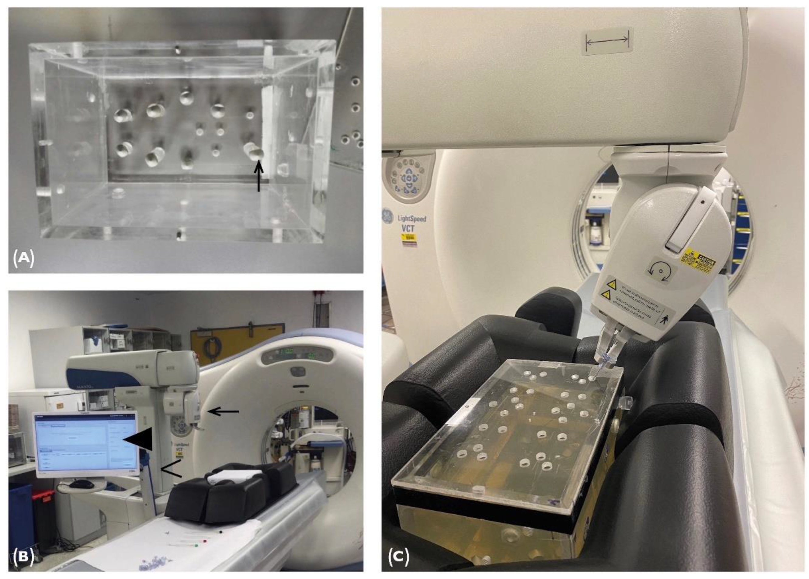
2.1. Phantom
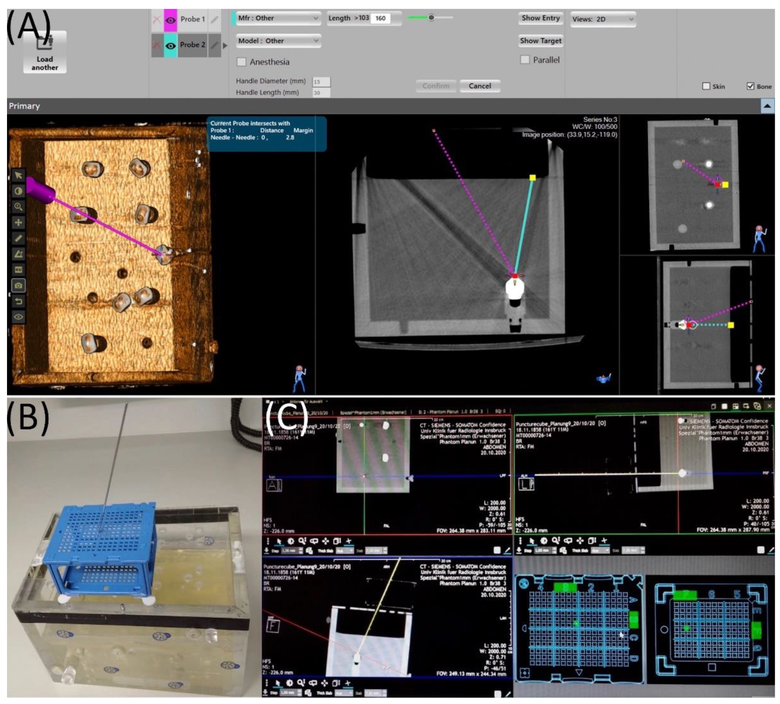
2.2. Maxio Roboti-assisted Needle Placement and Experimental Set-Up
2.3. Puncture Cube System and Experimental Setup
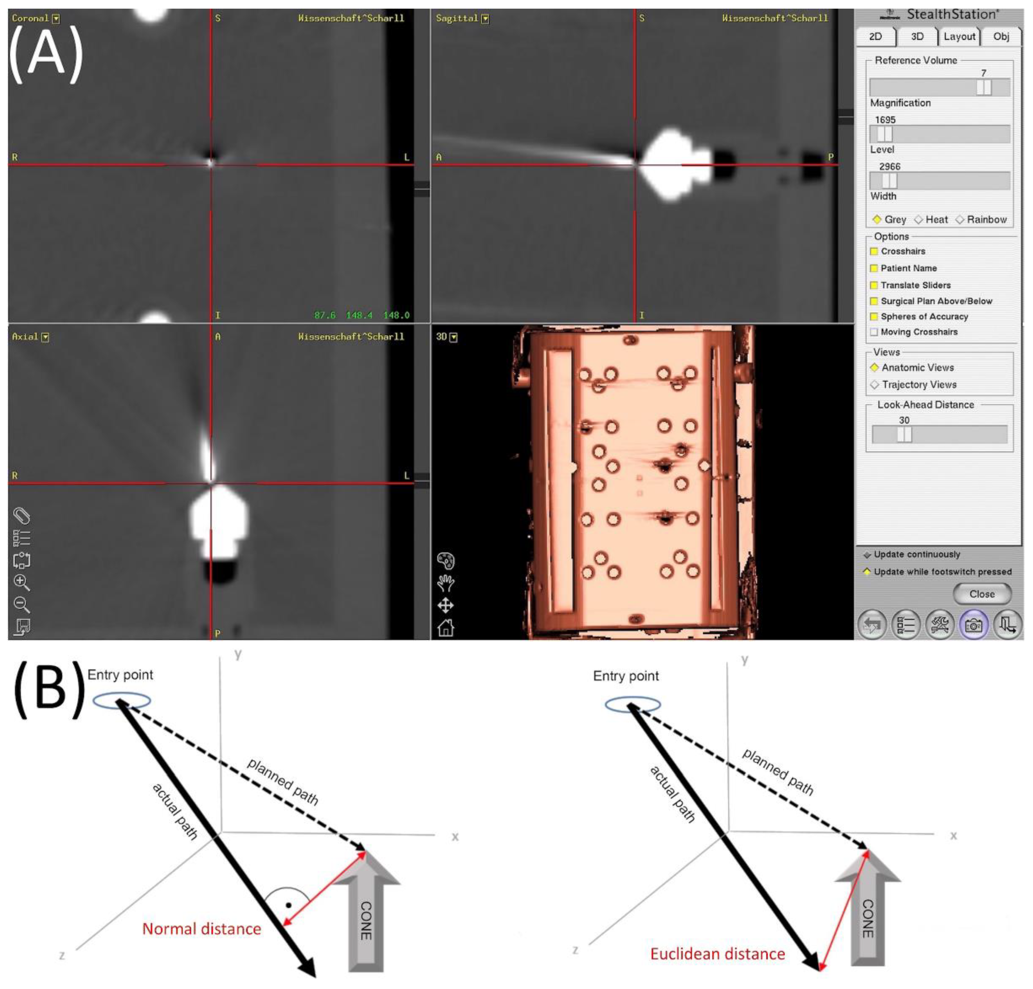
2.4. Evaluation
3. Results
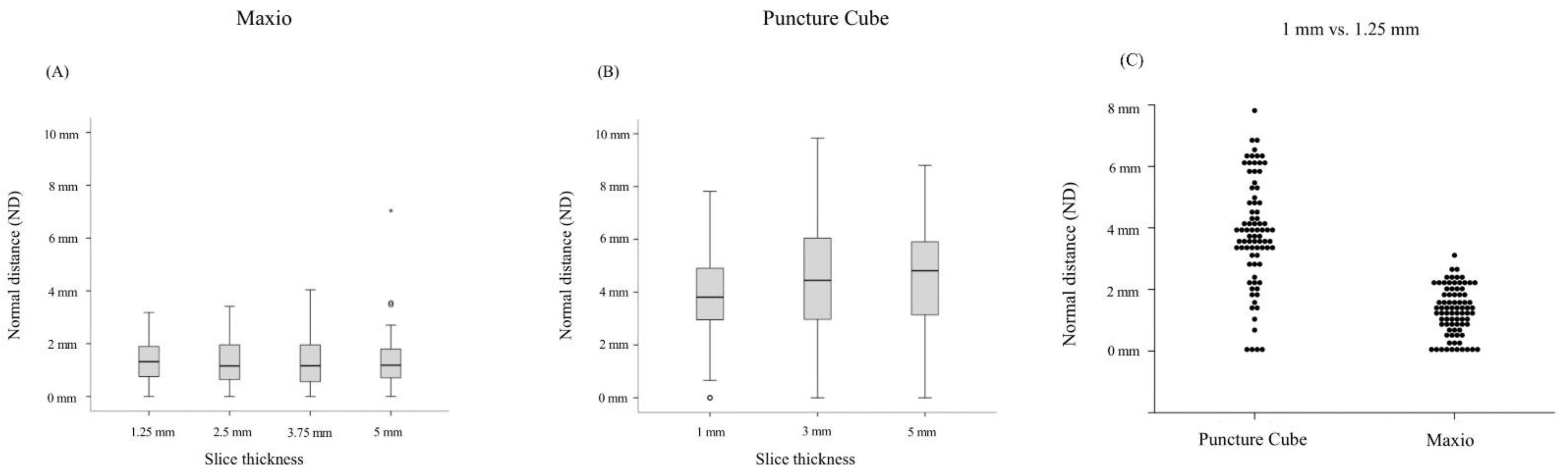
3.1. Maxio
3.2. PCS
3.3. Maxio vs. PCS
4. Discussion
5. Conclusions
Author Contributions
Funding
Institutional Review Board Statement
Informed Consent Statement
Acknowledgments
Conflicts of Interest
References
- Schullian, P.; Widmann, G.; Lang, T.B.; Knoflach, M.; Bale, R. Accuracy and diagnostic yield of CT-guided stereotactic liver biopsy of primary and secondary liver tumors. Comput. Aided Surg. 2011, 16, 181–187. [Google Scholar] [CrossRef] [PubMed]
- Bale, R.; Widmann, G.; Haidu, M. Stereotactic radiofrequency ablation. Cardiovasc. Interv. Radiol. 2011, 34, 852–856. [Google Scholar] [CrossRef] [PubMed]
- Magnusson, A.; Radecka, E.; Lönnemark, M.; Raland, H. Computed-tomography-guided punctures using a new guidance device. Acta Radiol. 2005, 46, 505–509. [Google Scholar] [CrossRef] [PubMed]
- Brabrand, K.; Aaløkken, T.M.; Krombach, G.A.; Günther, R.W.; Tariq, R.; Magnusson, A.; Lindgren, P.G. Multicenter evaluation of a new laser guidance system for computed tomography intervention. Acta Radiol. 2004, 45, 308–312. [Google Scholar] [CrossRef] [PubMed]
- Onik, G.; Cosman, E.R.; Wells, T.H., Jr.; Goldberg, H.I.; Moss, A.A.; Costello, P.; Kane, R.A.; Hoddick, W.I.; Demas, B. CT-guided aspirations for the body: Comparison of hand guidance with stereotaxis. Radiology 1988, 166, 389–394. [Google Scholar] [CrossRef]
- Minami, Y.; Kudo, M. Radiofrequency Ablation of Hepatocellular Carcinoma: A Literature Review. Int. J. Hepatol. 2011, 2011, 104685. [Google Scholar] [CrossRef] [Green Version]
- Barkhausen, J.; Kahn, T.; Krombach, G.A.; Kuhl, C.K.; Lotz, J.; Maintz, D.; Ricke, J.; Schönberg, S.O.; Vogl, T.; Wacker, F.; et al. White Paper: Interventional MRI: Current Status and Potential for Development Considering Economic Perspectives, Part 1: General Application. Rofo 2017, 189, 611–623. [Google Scholar] [CrossRef] [Green Version]
- Abdullah, B.J.J.; Yeong, C.H.; Goh, K.L.; Yoong, B.K.; Ho, G.F.; Yim, C.C.W.; Kulkarni, A. Robot-assisted radiofrequency ablation of primary and secondary liver tumours: Early experience. Eur. Radiol. 2014, 24, 79–85. [Google Scholar] [CrossRef] [PubMed] [Green Version]
- Mozer, P.; Troccaz, J.; Stoianovici, D. Urologic robots and future directions. Curr. Opin. Urol. 2009, 19, 114–119. [Google Scholar] [CrossRef] [PubMed]
- Roberts, C.C.; Morrison, W.B.; Deely, D.M.; Zoga, A.C.; Koulouris, G.; Winalski, C.S. Use of a novel percutaneous biopsy localization device: Initial musculoskeletal experience. Skelet. Radiol. 2007, 36, 53–57. [Google Scholar] [CrossRef] [PubMed]
- Stoffner, R.; Augschöll, C.; Widmann, G.; Böhler, D.; Bale, R. Accuracy and Feasibility of Frameless Stereotactic and Robot-Assisted CT-Based Puncture in Interventional Radiology: A Comparative Phantom Study. Rofo 2009, 181, 851–858. [Google Scholar] [CrossRef] [PubMed]
- Venturi, D.; Glossop, N.; Bale, R. Patient-specific templates for image-guided intervention—A phantom study. Minim. Invasive Ther. Allied Technol. 2019, 29, 251–260. [Google Scholar] [CrossRef] [PubMed]
- Putzer, D.; Arco, D.; Schamberger, B.; Schanda, F.; Mahlknecht, J.; Widmann, G.; Schullian, P.; Jaschke, W.; Bale, R. Comparison of Two Electromagnetic Navigation Systems For CT-Guided Punctures: A Phantom Study. Rofo 2016, 188, 470–478. [Google Scholar] [CrossRef] [PubMed] [Green Version]
- Bartsch, H.-J. Taschenbuch Mathematischer Formeln; Fachbuchverlag Leipzig: Leipzig, Germany, 2001. [Google Scholar]
- Koethe, Y.; Xu, S.; Velusamy, G.; Wood, B.; Venkatesan, A.M. Accuracy and efficacy of percutaneous biopsy and ablation using robotic assistance under computed tomography guidance: A phantom study. Eur. Radiol. 2014, 24, 723–730. [Google Scholar] [CrossRef] [PubMed] [Green Version]
- Mokry, A.; Willmitzer, F.; Hostettler, R.; Richter, H.; Kircher, P.; Kneissl, S.; Wetzel, S. Evaluation of a novel, patient-mounted system for CT-guided needle navigation-an ex vivo study. Neuroradiology 2019, 61, 55–61. [Google Scholar] [CrossRef] [PubMed]
- Croissant, Y.; Zangos, S.; Albrecht, M.H.; Eichler, K.; Schomerus, C.; Spandorfer, A.; Czerny, C. Robot-assisted percutaneous placement of K-wires during minimally invasive interventions of the spine. Minim. Invasive Ther. Allied Technol. 2019, 28, 373–380. [Google Scholar] [CrossRef] [PubMed]
- Laimer, G.; Jaschke, N.; Schullian, P.; Putzer, D.; Eberle, G.; Solbiati, M.; Bale, R. Volumetric assessment of the periablational safety margin after thermal ablation of colorectal liver metastases. Eur. Radiol. 2021, 31, 6489–6499. [Google Scholar] [CrossRef] [PubMed]
- Laimer, G.; Schullian, P.; Jaschke, N.; Putzer, D.; Eberle, G.; Alzaga, A.; Bale, R. Minimal ablative margin (MAM) assessment with image fusion: An independent predictor for local tumor progression in hepatocellular carcinoma after stereotactic radiofrequency ablation. Eur. Radiol. 2020, 30, 2463–2472. [Google Scholar] [CrossRef] [PubMed] [Green Version]

| ND | ED | |||||||
|---|---|---|---|---|---|---|---|---|
| Slice Thickness | Mean | SD | Min | Max | Mean | SD | Min | Max |
| 1.25 mm | 1.28 | 0.79 | 0 | 3.18 | 1.50 | 0.87 | 0 | 3.25 |
| 2.5 mm | 1.25 | 0.81 | 0 | 3.42 | 1.55 | 1.18 | 0 | 6.69 |
| 3.75 mm | 1.35 | 0.99 | 0 | 4.04 | 1.61 | 1.30 | 0 | 6.28 |
| 5 mm | 1.35 | 1.03 | 0 | 7.03 | 1.73 | 1.19 | 0 | 7.14 |
| ND | ED | |||||||
|---|---|---|---|---|---|---|---|---|
| Slice Thickness | Mean | SD | Min | Max | Mean | SD | Min | Max |
| 1 mm | 3.84 | 1.75 | 0 | 7.82 | 4.14 | 1.70 | 0 | 7.99 |
| 3 mm | 4.41 | 2.31 | 0 | 9.83 | 4.62 | 2.25 | 0 | 9.89 |
| 5 mm | 4.41 | 2.11 | 0 | 8.80 | 4.61 | 2.07 | 0 | 8.85 |
| ND | ED | ||
|---|---|---|---|
| Maxio | Mean and SD (mm) | 1.28 (±0.79) | 1.50 (±0.87) |
| Range (mm) | 3.18 | 3.25 | |
| PCS | Mean and SD (mm) | 3.84 (±1.75) | 4.14 (±1.70) |
| Range (mm) | 7.82 | 7.99 | |
| ArciNAV | Mean and SD (mm) | 1.42 (±0.66) | 2.52 (±0.64) |
| Range (mm) | 1.33 | 3.94 | |
| Stealth Station Treon | Mean and SD (mm) | 1.64 (±0.92) | 1.94 (±0.91) |
| Range (mm) | 4.57 | 4.79 | |
| Innomotion | Mean and SD (mm) | 1.42 (±0.78) | 1.69 (±1.42) |
| Range (mm) | 2.89 | 2.72 | |
| AxiEM | Mean and SD (mm) | 3.29 (±1.51) | 3.86 (±2.28) |
| Range (mm) | 9.61 | 14.70 | |
| PercuNav | Mean and SD (mm) | 3.76 (±1.59) | 4.42 (±1.33) |
| Range (mm) | 7.43 | 6.26 |
Publisher’s Note: MDPI stays neutral with regard to jurisdictional claims in published maps and institutional affiliations. |
© 2022 by the authors. Licensee MDPI, Basel, Switzerland. This article is an open access article distributed under the terms and conditions of the Creative Commons Attribution (CC BY) license (https://creativecommons.org/licenses/by/4.0/).
Share and Cite
Scharll, Y.; Mitteregger, A.; Laimer, G.; Schwabl, C.; Schullian, P.; Bale, R. Comparison of a Robotic and Patient-Mounted Device for CT-Guided Needle Placement: A Phantom Study. J. Clin. Med. 2022, 11, 3746. https://doi.org/10.3390/jcm11133746
Scharll Y, Mitteregger A, Laimer G, Schwabl C, Schullian P, Bale R. Comparison of a Robotic and Patient-Mounted Device for CT-Guided Needle Placement: A Phantom Study. Journal of Clinical Medicine. 2022; 11(13):3746. https://doi.org/10.3390/jcm11133746
Chicago/Turabian StyleScharll, Yannick, Alexander Mitteregger, Gregor Laimer, Christoph Schwabl, Peter Schullian, and Reto Bale. 2022. "Comparison of a Robotic and Patient-Mounted Device for CT-Guided Needle Placement: A Phantom Study" Journal of Clinical Medicine 11, no. 13: 3746. https://doi.org/10.3390/jcm11133746
APA StyleScharll, Y., Mitteregger, A., Laimer, G., Schwabl, C., Schullian, P., & Bale, R. (2022). Comparison of a Robotic and Patient-Mounted Device for CT-Guided Needle Placement: A Phantom Study. Journal of Clinical Medicine, 11(13), 3746. https://doi.org/10.3390/jcm11133746